EP0776132A2 - Système interactif de télévision - Google Patents
Système interactif de télévision Download PDFInfo
- Publication number
- EP0776132A2 EP0776132A2 EP96308572A EP96308572A EP0776132A2 EP 0776132 A2 EP0776132 A2 EP 0776132A2 EP 96308572 A EP96308572 A EP 96308572A EP 96308572 A EP96308572 A EP 96308572A EP 0776132 A2 EP0776132 A2 EP 0776132A2
- Authority
- EP
- European Patent Office
- Prior art keywords
- data
- remote control
- control apparatus
- user
- identifier
- Prior art date
- Legal status (The legal status is an assumption and is not a legal conclusion. Google has not performed a legal analysis and makes no representation as to the accuracy of the status listed.)
- Granted
Links
Images


Classifications
-
- H—ELECTRICITY
- H04—ELECTRIC COMMUNICATION TECHNIQUE
- H04N—PICTORIAL COMMUNICATION, e.g. TELEVISION
- H04N7/00—Television systems
- H04N7/16—Analogue secrecy systems; Analogue subscription systems
- H04N7/173—Analogue secrecy systems; Analogue subscription systems with two-way working, e.g. subscriber sending a programme selection signal
- H04N7/17345—Control of the passage of the selected programme
- H04N7/17354—Control of the passage of the selected programme in an intermediate station common to a plurality of user terminals
Definitions
- the present invention relates to an improved interactive television system whereby each user can employ a remote control apparatus to request specific services or to participate in electronic polling.
- such a system employs identification of respective remote control apparatuses which are actuated by users, and may also employ information identifiying users, or personal information relating to users, for purposes such as determining the validity of polling responses or the eligibility of respective users to participate in a poll or request a specific service.
- the center apparatus basically combines the functions of a computer network server apparatus, for sending/receiving data to/from remote terminal apparatuses via the network in accordance with a predetermined data communication protocol, together with functions for generating (in response to requests sent via the network from users) services such as television programs, e.g.
- Each terminal apparatus is a computer installation which functions as a client installation with respect to the center apparatus, i.e. requests and receives service data from the center apparatus, with the data being transferred via the network by utilizing an appropriate digital data communication protocol.
- the users of a terminal apparatus are provided with one or more remote control apparatuses, which can be actuated to send request data via the local terminal apparatus to the center apparatus, for requesting desired services.
- some television programs consist of (or may include) polls, e.g. whereby a survey can be taken of opinions of the users, or of a certain category of users. That is to say, it is possible to utilize such an interactive television system to provide the functions of an electronic polling system.
- polls e.g. whereby a survey can be taken of opinions of the users, or of a certain category of users.
- the term "polling” is used in a very general sense, which covers such concepts as a television quiz program in which users are asked to participate, an opinion survey (which may form example constitute only a portion of a television entertainment program), etc.
- the interactive television system may for example be temporarily put to use as an electronic polling system, during part of a television entertainment program which is provided to users of the interactive television system (as a service) on request.
- an interactive television system which provides services to users on demand and "an interactive television system which can be used as an electronic polling system”.
- Fig. 40 shows the basic configuration of such a system.
- the CATV network has been omitted, and only a single terminal apparatus is shown.
- polling requests are sent from a center apparatus 11001 to a terminal apparatus 11002, and displayed by a display apparatus 11003 to the users of that terminal apparatus.
- the user or users of the terminal apparatus 11002 In order to send their polling responses, the user or users of the terminal apparatus 11002 must use a telephone 1104 which can connect to the center apparatus 11001 via a public telephone line, i.e the user must dial a specified telephone number, wait for a response from the center apparatus, then inform the center apparatus of his/her response to the poll.
- a telephone 1104 which can connect to the center apparatus 11001 via a public telephone line, i.e the user must dial a specified telephone number, wait for a response from the center apparatus, then inform the center apparatus of his/her response to the poll.
- a survey such as a quiz program
- results are determined based on the time taken for respective polling responses to arrive, e.g. with the person who responds most rapidly to a question being the winner.
- respective amounts of transmission delays of the various telephone system paths used to send the polling responses which the users are not aware of, will affect the times taken for polling responses to be received. This is an obstacle to achieving polling that is fair.
- a third problem is as follows.
- a plurality of users may be accessing a single terminal apparatus at the same time.
- the terminal apparatus serves a single household
- various members of the family may be watching television together, i.e. may be using the terminal apparatus at the same time.
- the system may for some reason judge that a polling response sent by one user is not valid, and it would be desirable for the system to be able to individually notify the user in question of this fact.
- such a function is not practicable with the remote control apparatuses used in prior types of interactive television system, since the remote control apparatuses do not have a bidirectional communication function which can send information from the system to specifically identified remote control apparatuses, to be displayed thereby.
- a fourth problem arises with regard to storing personal attribute information of users of an interactive television system (in the following, the term "personal attribute information" will be used in a very general sense, to signify any information relating to a user, such as age, sex, home address, telephone number, etc.).
- personal attribute information will be used in a very general sense, to signify any information relating to a user, such as age, sex, home address, telephone number, etc.
- some applications for example in order to be able to effectively interpret the results of a survey which is performed by electronic polling using an interactive television system, is is desirable to have some personal attribute information available at the center apparatus. In that way it becomes possible for example to separately totalize polling results in various different categories of users, e.g. categorized in terms of age, in terms of area of residence, etc.
- comprehensive personal attribute information of users is held stored in a database at the center apparatus, then such personal information will be constantly available to any individuals who have access to the database at the center apparatus. Thus, there is a
- a further problem is as follows. For practical reasons, when conducting polling by using an interactive television system as an electronic polling system, it is necessary to set a time limit within which users must respond to polling request data which are sent from the center apparatus to the various terminal apparatuses (where the term "polling request data " as is used herein in the general sense of signifying data expressing the question or questions which the users will be asked to respond to). If for some reason a user does not respond immediately to that polling request data, then it is possible that the user will not notice or will forget the time limit that has been set for responding to the poll. This may results in the loss of the right to take part in the polling, for some users, and may cause a reduction of the total number of valid polling responses that are obtained.
- a second objective is to enable the polling to be free from effects of delay times of respective data transmission paths over which polling requests from the system and polling responses from users must travel.
- a third objective is to enable users to be individually notified of polling results, i.e. to enable specific result information to be supplied to only specific users.
- a fourth objective is to ensure the privacy of users, by ensuring that detailed personal information of users is not held fixedly stored in a computer installation which could be accessed by persons other than the respective users, but also ensuring that such information can be made available for the purpose of categorizing polling results obtained from the users, so that the polling results can be effectively evaluated and used.
- a sixth objective is to minimize the quantity of data which must be transferred within the interactive television system during polling.
- a seventh objective is to enable the users' polling rights to be effectively utilized, by ensuring as far as possible that users will not inadvertently lose the right to participate in a poll.
- An eighth objective is to provide an interactive television system which can provide various services on demand from users, while ensuring that specific users, or specific categories of users, can be accurately identified by the system. Such a system can thereby determine, in accordance with the particular user or category of user, the types of service which will be provided to a user in response to a request that is input to the system by using a remote control apparatus.
- a ninth objective is to provide an interactive television system in which identification of respective users or respective remote control apparatuses by the system is possible, and whereby information for use in identifying a user or a remote control apparatus can be sent to the system from an remote control apparatus in encrypted code form, to thereby ensure improved security.
- a tenth objective of the invention is to provide an interactive television system for supplying services to users on demand, whereby a restriction control code can be superimposed on data of a specific service which is provided to a user by the system, and whereby, when such a restriction control code is superimposed on the service data, such service data will be prevented from being made visible/audible to the user unless the system has identified the user as being within a category of users who are authorized to receive that service.
- An eleventh objective of the invention is to provide an interactive television system for supplying services to users on demand, whereby it becomes unnecessary for a user to execute repetitive data input operations in relation to successive displayed menu pages, in order to locate a desired service within a large number of services which are available from the interactive television system and to input to the system a request for such a desired service.
- the present invention provides an interactive television system formed of a center apparatus, a plurality of terminal apparatuses which can perform bidirectional communication with the center apparatus via a data communication network capable of transmitting video data, such as a CATV network, whereby it a basic feature of the present invention that each remote control apparatus is assigned an identifier, e.g. an identifier number, and each terminal apparatus is also assigned an identifier, enabling the center apparatus to identify a remote control apparatus which originates a request for a service or sends a polling response, and whereby the center apparatus can send appropriate service data to the terminal apparatus corresponding to the originating remote control apparatus or can send messages directed to the users of specific remote control apparatuses.
- a data communication network capable of transmitting video data
- each remote control apparatus is assigned an identifier, e.g. an identifier number
- each terminal apparatus is also assigned an identifier, enabling the center apparatus to identify a remote control apparatus which originates a request for a service or sends a polling response, and where
- the term "message data set” will be used as a general term to refer to a data set which is sent from a remote control apparatus to a terminal apparatus or from a terminal apparatus to the center apparatus, consisting of (at least) polling request data with the identifier of the originating remote control apparatus attached thereto, or consisting of service request data with the identifier of the originating remote control apparatus attached thereto.
- the identifiers assigned to the remote control apparatuses and to the terminal apparatuses are respectively unique within the system, while the center apparatus holds information which relates the remote control apparatus identifiers to their respective terminal apparatus identifiers. In that case, it is unnecessary for the terminal apparatus identifier to be attached to data which are sent from a remote control apparatus via its terminal apparatus to the center apparatus. However the center apparatus must store information relating each remote control apparatus identifier to the identifier of the corresponding terminal apparatus. Such an arrangement is assumed in the various embodiments of the invention described hereinafter.
- each remote control apparatus can be provided with user identification means.
- Such means can include key input means for a user to input a predetermined code or password, and means for recognizing that code or password.
- each remote control apparatus can be provided with fingerprint recognition means, or voice pattern recognition means, and can store data for use in identifying fingerprint or voice pattern of a registered user.
- Each remote control apparatus can also include means for storing personal information relating to a registered user, and means for attaching that information to message data which is input by the user, to be sent to the center apparatus, while no such personal information are sent to the center apparatus when message data are input by some other user, i.e. a non-authorized user.
- message data which are input by a user can only be sent from the remote control apparatus to the center apparatus if the user has been recognized by the aforementioned identification means.
- the invention provides an interactive television system comprising a center apparatus, a plurality of terminal apparatuses, a plurality of display apparatus and a plurality of remote control apparatuses, the terminal apparatuses being respectively configured for bidirectional data communication with the center apparatus via a digital data communication network and each configured for receiving data by a wireless communication link from at least a corresponding one of the remote control apparatuses and for supplying to a corresponding one of the display apparatuses, data sent thereto from the center apparatus; wherein each remote control apparatus comprises means for input of message data by a user, means for storing a predetermined remote control apparatus identifier, means for reading out and attaching at least the remote control apparatus identifier to the user message data to form a message data set, and means for sending the message data set via the wireless communication link to the terminal apparatus, each terminal apparatus comprises means for storing a predetermined terminal apparatus identifier, means for receiving a message data set which is sent from a remote control apparatus, and means for sending the message data set
- the wireless communication link which connects each remote control apparatus to a terminal apparatus can be a bidirectional data communication link and each remote control apparatus can include data display means.
- the resultant data which are sent by the center apparatus to a terminal apparatus may include user-directed data which are directed to a specific remote control apparatus as designated by a remote control apparatus identifier, and wherein terminal apparatus may comprise means for supplying the user-directed data to the specific remote control apparatus via the wireless communication link, to be displayed by the data display means of the remote control apparatus.
- the center apparatus comprises means for judging each received message data set in accordance with predetermined criteria, and for selectively generating, based on results of the judgement, the user-directed data which are to be sent to a remote control apparatus corresponding to a remote control apparatus identifier contained in the received message data set.
- each of the remote control apparatuses further comprises
- the means for inputting the user-specifying data may comprise a plug-in integrated circuit card and interface means for electrically connecting the plug-in integrated circuit card to the remote control apparatus, the integrated circuit card having mounted thereon an integrated circuit operable for supplying data or signals which have been predetermined as being specific to an individual user.
- the means for inputting the user-specifying data may comprise key input means, manually actuatable by a user for inputting a password code which has been predetermined as being specific to an individual user.
- the means for inputting the user-specifying data may comprise fingerprint scanning means and fingerprint pattern processing means for operating on information obtained from the fingerprint scanning means to generate fingerprint pattern data, with the stored user-specifying data comprising fingerprint pattern data which have been predetermined as being specific to an individual user.
- the means for inputting the user-specifying data may comprise microphone input means for generating an audio signal in response to voice input by a user, and voice pattern processing means for operating on the audio signal to derive voice pattern data, with the stored user-specifying data comprising voice pattern data which have been predetermined as being specific to an individual user.
- the invention can provide such an interactive television system which is configured such that the system can take a poll of respective users of the remote control apparatuses, wherein the user message data comprises polling response data, wherein each of the remote control apparatuses comprises means for storing a set of predetermined personal attribute information items relating to a corresponding user, and wherein the center apparatus comprises means for sending a polling request data set to each of the terminal apparatuses via the network, the polling request data set comprising polling request data, a personal attribute information list specifying a list of personal attribute information items, and polling eligibility conditions data for specifying conditions whereby a user is made eligible to participate in the polling, each terminal apparatus comprises means for receiving the polling request data set, extracting the polling eligibility conditions data from the polling request data set and temporarily storing the polling eligibility conditions data, supplying the polling request data to be displayed by the corresponding data display apparatus, and sending the personal attribute information list to each of the corresponding remote control apparatuses; each remote control apparatus comprises means for receiving the personal
- the center apparatus may also comprise means for comparing each remote control apparatus identifier of a received message data set with respective remote control apparatus identifiers which have been previously received and stored, for thereby detecting reception of multiple responses from any of the remote control apparatuses, and means for inhibiting use of the polling response data an personal attribute information contained in the message data set in deriving the polling result data.
- each remote control apparatus comprises data display means
- the center apparatus comprises means responsive to the detection of multiple responses from a remote control apparatus for generating data of a warning message, attaching the warning message data to the identifier of the remote control apparatus to form a warning message data set and for sending the warning message data set via the data communication network to the terminal apparatus having a terminal apparatus identifier which corresponds to the remote control apparatus identifier of the remote control apparatus
- each terminal apparatus comprises means responsive to receiving a warning message data set for extracting the remote control apparatus identifier therefrom and sending the warning message data to the corresponding remote control apparatus, to be displayed by the data display means of the remote control apparatus.
- each terminal apparatus further comprises means for measuring, for each of the corresponding remote control apparatuses, an elapsed time amount which occurs from a commencement of the displaying of the polling request data until a message data set containing the polling response data is received from the remote control apparatus, and means for sending the elapsed time amounts in conjunction with respectively corresponding remote control apparatus identifiers, as resultant data, to the center apparatus via the data communication network, with the center apparatus further comprising means for analyzing the resultant data received from the terminal apparatuses to obtain, as polling result data, data relating the remote control apparatus identifier to successively increasing values of the elapsed time amounts, and means for sending the polling result data to the terminal apparatuses.
- the invention provides such an interactive television system, but wherein the center apparatus includes means for selectively providing data of a plurality of services, each of the terminal apparatuses being configured for supplying, to the corresponding one of the display apparatus, service data which are sent thereto from the center apparatus; wherein each remote control apparatus comprises
- the system can ensure that specific restricted services, such as certain television entertainment programs or films, are supplied only to the users of certain registered remote control apparatuses, while non-restricted services are available to all users of the system.
- each remote control apparatus may comprise bar code scanner means, operable to acquire the service request data by scanning a bar code which appears on printed matter.
- each remote control apparatus can further comprise
- each remote control apparatus may further comprise
- the center apparatus may comprise
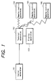
- Fig. 1 is a conceptual diagram illustrating the structure of such an interactive television system.
- 101 denotes a center apparatus which executes processing relating to polling, transmits television programs and computer programs as required, receives and totalizes polling responses, and returns polling results.
- Each of the embodiments of the present invention described in the following will be assumed (for the purpose of description) to be a CATV system which provides services such as television programs on demand, and/or electronic polling.
- the invention is basically applicable to various types of data communication systems whereby video data or (video + audio) data can be generated at a central installation and transmitted on demand via a network (which can be local area network or wide-area network) to various users.
- the term "center apparatus" as used in the following is to be understood as signifying a central installation of a CATV system, formed of one or more computer systems, video data storage devices, etc., which originates service data such as television programs and/or polling data, and implements network server functions (i.e. using a suitable data communication protocol) to transmit the data via a digital data communication network such as a CATV (cable television) network to respective terminal apparatuses.
- terminal apparatus as used in the following is to be understood as signifying a computer installation which uses the aforementioned communication protocol for bidirectional communication with the center apparatus via the CATV network, and which also implements bidirectional communication (in general, via a wireless optical link) with each of a set of one or more remote control apparatuses.
- the terminal apparatus may for example implement the aforementioned communication protocol by means of program routines stored in a ROM (Read only Memory), or may operate by executing computer programs which has been sent from the center apparatus and stored in memory.
- 103 denotes a display apparatus which generates a video display picture, based on video data or a video signal that is output from the terminal apparatus 102.
- 104, 105 and 106 denote respective remote control apparatuses, for use by by respective users of the system.
- the users obtain information that is sent from the center apparatus 101 by observing the display apparatus 103, and operate the remote control apparatuses 104, 105, 106 accordingly, to send data to the terminal apparatus 102.
- Resultant processing is executed by the terminal apparatus 102, and data are sent to the center apparatus 101.
- Polling results are sent by the center apparatus 101 via the terminal apparatus 102 to the remote control apparatuses 104, 105, 106.
- the center apparatus 101 communicates via a CATV network 100 with a plurality of terminal apparatuses, one of which is designated as terminal apparatus 102.
- the terminal apparatus 102 supplies data (e.g. in the form of a video signal, or data which can be converted to a video signal by circuits in the display apparatus 103) to the display apparatus 103.
- each of the remote control apparatuses which communicate with the terminal apparatus 102 can be provided with a set of data input keys 107, such as a numeric or alphanumeric key pad, whereby users can input data such as requests for services or responses to polling requests, to the system.
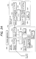
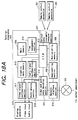
- FIGs. 3A, 3B (collectively referred to in the following simply as Fig. 3) show the configuration of this embodiment in the form of a basic block system diagram, showing the center apparatus of the system, one of the terminal apparatuses of the system, and one of the remote control apparatuses which is linked to that terminal apparatus. It should be understood that the various system blocks which are shown as performing specific functions in the the center apparatus, terminal apparatus and remote control apparatus in Fig. 3 are to taken as purely conceptual, since the respective operating functions are actually performed by computer program operations.
- an "I/O interface section" of a terminal apparatus for executing data communication via a network will in practice be implemented by computer program routines, stored in memory, which are invoked and executed when necessary for implementing a specific data communication protocol to send or receive data from or to the center apparatus.
- 2100 denotes a center apparatus
- 2101 denotes a central processing unit which executes processing of programs for the center apparatus.
- 2102 denotes a monitoring section which monitors the polling contents.
- 2103 denotes a polling conditions management section which manages conditions that define polling eligibility.
- 2104 denotes an attribute automatic totalizing section which executes data totalization based on personal attribute information which is attached to the polling response data.
- 2105 denotes a data base section, which stores personal attribute information of users, polling data, etc.
- 2106 denotes a network interface to a digital CATV network.
- 2200 denotes a terminal apparatus.
- 2201 denotes a central processing unit which executes processing of programs for the terminal apparatus.
- 2202 denotes a network interface section to the digital CATV network.
- 2203 denotes an I/O interface section, for executing communication with the remote control apparatuses, via respective wireless data communication links such as optical data communication links.
- 2204 denotes a main memory for storing information.
- 2205 denotes a non-volatile data storage section, for storing attributes of the terminal apparatus.
- 2206 is a polling schedule management section for managing polling validity times, response time limits, etc.
- 2207 denotes a polling management section, for checking the polling conditions.
- 2300 denotes a remote control apparatus.
- 2301 denotes a central processing unit for executing processing of programs relating to the remote control apparatus.
- 2302 denotes an I/O (input/output) interface section for executing communication with the terminal apparatus.
- 2304 denotes an information display section for displaying information.
- 2305 denotes a non-volatile data storage section for storing attributes of the remote control apparatus.
- 2306 denotes a personal attribute information storage section, for storing personal attribute information of a user.
- 2307 denotes an input section, (such as a numeric or alphanumeric keyboard as mentioned above, in conjunction with a suitable interface) for inputting the user personal attribute information and for inputting polling response data.
- a display apparatus i.e. providing the video and audio output functions of a usual television receiver, for reproducing video and audio data, supplied from the terminal apparatus 2200.
- a display apparatus i.e. providing the video and audio output functions of a usual television receiver, for reproducing video and audio data, supplied from the terminal apparatus 2200.
- video display function of such a display apparatus will be mentioned in the following description, however it should be understood that in practice, both video and audio display/output will be provided.
- the user inputs personal attribute information to the remote control apparatus 2300, e.g. by actuating data input keys of the remote control apparatus.
- This input is executed via the input section 2307, and the personal attribute information is stored in the personal attribute information memory section 2306.
- Fig. 4 shows an example of the personal attribute information.
- the non-volatile data memory section 2305 of the remote control apparatus 2300 has stored therein a remote control apparatus identifier, e.g. an identification number, which is unique within the entire system.
- the non-volatile data memory section 2205 of the terminal apparatus 2200 also has stored therein an identifier, e.g. an identification number, which is unique to the entire system.
- Fig. 5 is an example of the relationships established between such remote control apparatus and terminal apparatus identification numbers and corresponding sets of personal attribute information items. It is assumed in this example that the embodiment is applied to a CATV system which is connected to various homes of users. Within each home, one or more family members may be assigned respective remote control apparatuses (with each remote control apparatus having stored therein personal attribute information for the corresponding user, as described above). However the personal attribute information items which are stored at the center apparatus as shown in Fig. 5 constitute only a small part of the personal attribute information for each user, i.e. an this example, the name, address, and telephone number of each user.
- the terminal apparatus which is installed in the Jones household is linked to three remote control apparatuses, which are assigned to three different family members and so have respectively different remote control apparatus identification numbers.
- Polling request data which are output from the central processing unit 2101 of the center apparatus 2100 are broadcast via the network interface sections 2106 and 2202 to each of the terminal apparatususe 2200 of the system.
- the polling request data received by each terminal apparatus are processed by the central processing unit 2201, and supplied to the display apparatus 2400 in suitable form for being displayed thereby.
- a user Based on the polling request data which are displayed by the display apparatus 2400, a user operates the remote control apparatus 2300 to input a polling response.
- the polling request data are sent from the center apparatus 2200 to the terminal apparatus 2200 together with polling eligibility conditions, a personal attribute information attachment list (which is a list of personal attribute information items which are to be attached to the polling response data which will be sent back from the remote control apparatus of a user), and polling validity term data (which specify the time duration during which polling responses can be accepted from users), respectively attached to the polling request data.
- polling request data set i.e. polling request data together with polling eligibility condition information, a personal attribute information list, and polling validity term data
- Fig. 6 shows an example of the configuration of such a polling request data set.
- a polling request data set which is received by the terminal apparatus 2200 is stored in the main memory 2204 and analyzed by the central processing unit 2201, to extract the polling eligibility conditions, the personal attribute information attachment list, and the polling validity term data.
- the polling eligibility conditions are stored in the polling management section 2207
- the polling validity term data are stored in the polling schedule management section 2206.
- the personal attribute information list is transmitted via the I/O interface sections 2203 and 2302 to each remote control apparatus 2300.
- the central processing unit 2301 of the remote control apparatus 2300 attaches, to the polling response data which are input by the user from the input section 2307, personal attribute information items which are extracted from the contents of the personal attribute information memory section 2306, as specified by the personal attribute information attachment list, and also attaches the remote control apparatus identification number that is stored in the non-volatile data memory section 2305, to thereby generate a set of data which will be referred to as a polling response data set. That data set is sent via the I/O interface sections 2302 and 2203 to the terminal apparatus 2200.
- Fig. 7 shows an example of such a polling response data set.
- the polling management section 2207 checks the contents, and if the polling eligibility conditions are satisfied, the terminal apparatus 2200 sends the polling response data set to the center apparatus, or temporarily stores the polling response data set, to subsequently send all received polling response data sets to the center apparatus.
- the terminal apparatus sends all of the polling response data sets to the center apparatus, and deletes the polling term data which have been stored in the polling schedule management section 2206.
- the terminal apparatus can be configured to send each polling response data set (which meets the eligibility conditions) directly to the center apparatus when it is received from a remote control apparatus.
- polling eligibility conditions are not met by a polling response data set which is received by the terminal apparatus, then data for an error message are sent by the terminal apparatus to the corresponding remote control apparatus 2300, to be displayed by the information display section 2304 of the remote control apparatus 2300. The user is thereby notified that his/her polling response has not been allowed.
- the central processing unit 2101 When a polling response data set, sent from a terminal apparatus 2200, is received by the center apparatus 2100, the central processing unit 2101 extracts the remote control apparatus identification number, the personal attribute information, and the user input data which are attached to the polling response data, and stores these in the data base section 2105.
- the center apparatus checks to ensure that multiple responses have not been sent from the same remote control apparatus, i.e. by the same user. This is done by checking that the remote control apparatus identifier of a received response is not identical to that of any remote control apparatus identifier which has already been received and stored as described above. If a second occurrence of the same remote control apparatus identification number is detected, then the monitoring section 2102 notifies the central processing unit that a polling response has already been received from the remote control apparatus concerned, so that the latest polling response received from that remote control apparatus is not valid. In that case, the center apparatus generates data of a warning message, and attaches thereto the identifier of the remote control apparatus concerned, to form a warning message data set.
- the center apparatus determines the terminal apparatus identifier corresponding to that remote control apparatus identifier, and sends the warning message data set via the network to the appropriate terminal apparatus 2200. That terminal apparatus then sends the warning message data to the remote control apparatus 2300 concerned. On receiving the warning message data, that remote control apparatus 2300 displays a warning message by the information display section 2304, thereby notifying the user that her or she has input multiple polling responses.
- the received polling response data are totalized by the center apparatus in accordance with user personal attributes, based on the personal attribute information which has been attached to the polling response data.
- Fig. 8 shows an example of the data totalized in that manner.
- the poll consists of an opinion survey of users
- the personal attribute information item which is specified in the personal attribute information list is "age of user”
- the polling result data are classified according to respective age ranges of the responding users, as shown.
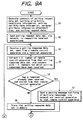
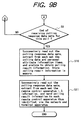
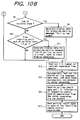
- Figs. 9A, 9B constitute a flow diagram of an example of the processing executed by the center apparatus of this embodiment
- Figs. 10A, 10B constitute a flow diagram of an example of corresponding processing executed by a terminal apparatus of this embodiment
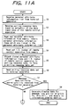
- Figs. 11A, 11B constitute a flow diagram of an example of corresponding processing executed by a remote control apparatus of this embodiment.
- polling result data are supplied by the system only to those users who have participated in the poll, i.e. that the result data are sent to the respective remote control apparatuses of those specific users, to be displayed by each remote control apparatus.
- the polling results could simply be broadcast from the center apparatus to all of the terminal apparatuses, to be displayed by their respective display apparatuses to all of the users.
- a first characterizing feature of the above embodiment it is possible to inherently prevent multiple polling responses by the same user, thereby preventing the polling results from being biased towards specific users.
- polling results can be directed by the center apparatus to specific remote control apparatuses (i.e. each identified by the corresponding remote control apparatus identifier), it is possible to provide specific information, such as warning indications, to individual users.
- specific information such as warning indications, to individual users.
- detailed user personal attribute information can be be input by each user to his/her personal remote control apparatus, to be stored in that remote control apparatus, but held inaccessible to other users of the system.
- the burden of managing the personal attribute information is distributed among the remote control apparatuses, so that the data processing load imposed on the center apparatus can be minimized.
- various processing which Is necessary to execute polling can be performed by the various terminal apparatuses, so that it is only necessary to transmit to the center apparatus, for each polling response, a minimum amount of necessary data (i.e. the polling response data, the remote control apparatus identifier, and any specified item or items of personal attribute information of a user).
- a minimum amount of necessary data i.e. the polling response data, the remote control apparatus identifier, and any specified item or items of personal attribute information of a user.
- polling time limits can be automatically notified to the users, so that polling rights of users can be effectively utilized (i.e. there is a reduced possibility that users may fail to participate in polling as a result of inadvertently delaying the sending of a polling response beyond the specified response time limit).
- Fig. 12 is a system block diagram of the basic configuration of this embodiment, which is also an interactive television system which functions as an electronic polling system.
- a diagram shows only basic concepts, while the functions indicated shown are actually implemented by respective computer programs which are executed by the center apparatus, by each terminal apparatus and by each remote control apparatus of the system.
- the operations executed by a single terminal apparatus and by a single remote control apparatus which is linked to that terminal apparatus will be described.
- 9100 denotes a center apparatus
- 9101 denotes a central processing unit for executing processing of programs for the center apparatus
- 9102 denotes a network interface to a digital CATV network
- 9103 denotes a database section for storing personal attribute information of users and polling data.
- 9200 denotes a terminal apparatus
- 9201 denotes a central processing unit for executing processing of programs for the terminal apparatus
- 9202 denotes a network interface to the digital CATV network
- 9203 denotes an I/O interface section for use in communicating with remote control apparatuses
- 9204 denotes a response time management section for measuring and recording response times that elapse from the time that a polling request starts to be displayed by a display apparatus 9400 until polling is executed by users of the corresponding remote control apparatuses 9300.
- polling request data which are output by the central processing unit 9101 of the center apparatus 9100 are distributed to each terminal apparatus 9200 through a CATV network 9000 via the network interface sections 9102, 9202.
- the polling request data received by the terminal apparatus 9200 are processed by the central processing unit 9201, and are displayed by the display apparatus 9400.
- the response time management section 9204 measures and records response times that elapse from the time that a polling request starts to be displayed by the display apparatus 9400 until polling is executed by respective users, i.e. the time which elapses until a user inputs a polling response from a remote control apparatus 9300 through the I/O interface section 9203 of the terminal apparatus.
- each remote control apparatus 9300 attaches, to polling response data which are input by the user, the remote control apparatus identifier, to thereby form a polling response data set, which is then sent to the terminal apparatus 9200.
- the central processing unit 9201 of the terminal apparatus then attaches, to that polling response data set, data expressing the value of response time which has been measured for that response by the response time management section 9204, to thereby form a complete polling response data set, and sends this via the network 9000 to the center apparatus 9100.
- the central processing unit 9101 of the center apparatus 9100 extracts the response time data from the polling response data set thus received, and stores the polling response data in the database section 9103.
- Respective polling response times which are thus obtained are arranged and stored (in conjunction with the respectively corresponding remote control apparatus identifiers) in a sequence which is determined by the respective response time values, i.e. arranged successively beginning from the shortest value, to thereby obtain the polling results.
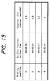
- Fig. 13 shows an example of the relationship between the polling sequence, the times at which polling responses are received by the center apparatus, and response time intervals. This illustrates that the polling results are independent of the times at which polling responses are received from the terminal apparatuses, but depend only upon the respective response time intervals.
- the response times of respective users with respect to each terminal apparatus are used as a reference for determining the arrival sequence of polling responses, so that the polling response sequence can be established in a fair manner, which is not affected by delays of respectively different transmission paths over which response data ore sent to the center apparatus from the various users.
- the polling response sequence can be fairly established, irrespective of differences between delay times of different communication paths by which responses are sent to the center apparatus by respective users.
- the center apparatus can send respectively separate messages (for example, to indicate to a specific user his or her position in the polling results) to each of various remote control apparatuses that are being used, with respectively different information being thereby displayed by the various remote control apparatuses.
- each of the remote control apparatuses can stored detailed personal attribute information of a user, however but only that part of the personal attribute information which is actually necessary for the purpose of executing a particular poll is transmitted from the remote control apparatus of a user to the corresponding terminal apparatus and the center apparatus, and that personal information is used only for the time required to analyze the polling results, i.e. need not be held stored for any substantial time at any position in the system other than in the personal remote control apparatus of a user. Hence, the possibility of violation of user privacy can be prevented. In addition, this enables the function of management of personal attribute information to be distributed among the remote control apparatuses, so that it becomes possible to prevent a concentration of information handling load on the center apparatus.
- the polling results can be analyzed in terms of various types of personal attributes, thereby enabling the polling response data to be effectively analyzed and utilized.
- polling eligibility conditions can be established whereby polling is limited to only those users who are appropriate for participating in a specific poll. For example, some types of survey can be limited to adults, while others can be limited to children.
- Such a feature also has the advantage that, since unnecessary responses can be eliminated from being transmitted from remote control apparatuses through the system to the center apparatus, the number of polling responses received by the center apparatus can be minimized to only the necessary number, thereby enabling the total amount of transmitted data to be minimized. This enables efficient use of communication paths such as a CATV network.
- the polling management load is more effectively distributed within the system, i.e. among the remote control apparatuses rather than being excessively concentrated on the center apparatus.
- polling validity term data can be attached to the polling request data. As described above, this can be used to notify the users when the end of the term for sending polling responses becomes close, reducing the possibility of users inadvertently omitting to send responses.
- Fig. 14 is a flow diagram of an example of the operations executed by the center apparatus of the above second embodiment, to carry out a poll of users of the system.
- Figs. 15A, 15B constitute a flow diagram of a corresponding example of the operations which would be executed by a terminal apparatus of the above embodiment, while Fig. 16 is a flow diagram of an example of the operations executed by a remote control apparatus of the above embodiment.
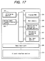
- FIG. 17 is a diagram showing the configuration of a remote control apparatus of this embodiment.
- Figs. Fig. 18A and 18B constitute a conceptual block system diagram showing the general configuration of an interactive television system according to this embodiment. In the same way as for the preceding embodiments, only a single terminal apparatus of the system is shown, for simplicity of description.
- the terminal apparatus 306 receives message data, i.e. service request data, from remote control apparatuses 301, via an optical data transmit/receive section 307, i.e. it is assumed that bidirectional communication with the remote control apparatuses is possible, although that is not essential for this embodiment.
- Operations executed by the terminal apparatus are controlled by processing executed by a CPU 312, in accordance with a program which is stored in a non-volatile memory 308, which also holds the remote control apparatus identifier.
- the terminal apparatus 306 executes bidirectional data communication with the center apparatus 330 via a CATV network 320.
- the data are transferred via the network interface section 310 (i.e.
- the CPU 312 itself can generate audio and video data, for providing warning messages etc. to users, by data supplied to an audio signal synthesizing section 314 and a graphics data memory 315 and video signal synthesizing section 317, which can also be used by the CPU 312 to selectively enable or inhibit the supply of the aforementioned video and audio signals of a service (transmitted from the center apparatus) to the display apparatus 319.
- the center apparatus 330 of this embodiment includes a section, indicated as the data streamer 327, whereby data of various services can be generated as required (i.e. in response to user requests sent in the form of request data sets) and supplied via a network interface section 322 and the CATV network to the terminal apparatuses of respective users.
- the center apparatus 330 also includes a database section 326, which stores data including information relating to various users, information which relates each terminal apparatus identifier to the respectively corresponding remote control apparatus identifiers as described for the preceding embodiments, etc.
- the remote control apparatus of this embodiment shown in Fig. 17 is provided with a key input processing section 208 (e.g.
- a user can input message data such as service requests, to be processed by a program which is executed by a CPU 203, with the program data being stored beforehand in a program ROM 204.
- Resultant data are transmitted to the corresponding terminal apparatus by an opto-emissive transmitting section 202.
- the terminal apparatus is provided with a corresponding opto-receptive receiving section, so that a data communication link is established.
- this remote control apparatus is provided with a personal information storage section 206, having stored therein a remote control apparatus identifier, which will be assumed to be an identifier number, i.e. which identifies that particular remote control apparatus.
- the personal information storage section 206 also has stored therein user identification information.
- user identification information Various types of information could be utilized as this user identification information.
- the information could consist of one or more personal attribute information items, as described hereinabove for the preceding embodiments.
- the user identification information could simply consist of a identification number, which is uniquely assigned to a specific user, or to a specific category of user. In general in the following, such a user or user category will be referred to as an "authorized user" or "category of authorized users”.
- the personal information storage section 206 also has stored therein information which can be used by the remote control apparatus itself, to recognize that a user is an authorized user.
- information will be referred to in the following as user-specifying information. It will first be assumed that this stored user-specifying information consists of a code, such as a password.
- this stored user-specifying information consists of a code, such as a password.
- a user before inputting message data to be sent to the center apparatus, a user must first input the necessary password, by using the key input section 208. Processing is then executed to read out the stored password and compare this with the input password. If these are identical, then this indicates that the remote control apparatus is being used by an authorized user.
- the user e.g.
- message data such as data to request a specific service
- the remote control apparatus identifier and the user personal information will be read out and attached to the service request data, to form a data set which will be referred to as a "request data set”.
- This is then sent to the corresponding terminal apparatus, via the aforementioned optical data communication link, and then transferred via the CATV network to the center apparatus.
- an encryption processing section 207 can be included.
- the user personal information can first be encrypted, and the encrypted code transmitted in place of the user personal information, in the request data set.
- the terminal apparatus is capable of decrypting such encrypted information, i.e. is provided with a suitable decryption key, to recover the user personal information information.
- This provides increased security, since there is a reduced possibility that user personal information could be interecepted by unauthorized individuals and used to access the system.
- the encryption processing section 207 can be omitted, and the user personal information can be directly attached to the request data set.
- an IC (integrated circuit) interface section can be provided in the remote control apparatus, i.e. a receptacle for a plug-in card having a specific type of IC mounted thereon, enabling the IC to be electrically connected via a data input port 209 to the CPU 203 of the remote control apparatus.
- the IC can for example be a small ROM (read-only memory) or data register having a specific code fixedly stored therein, with a corresponding user-specifying code being held in the personal information storage section 206.
- a user before inputting message data, e.g. before inputting service request data, a user must first insert the appropriate IC card into the interface section 210.
- the CPU 203 executes processing to compare the data provided by the IC card with the user-specifying code which is stored in the personal information storage section 206, to effect recognition of an authorized user.
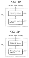
- the remote control apparatus of this embodiment can be configured to include a fingerprint information generating section, as illustrated in Fig. 19.
- the fingerprint information generating section 215 consists of a fingerprint scanning section 212, which can scan a user's fingerprints to obtain resultant signals, and a fingerprint pattern processing section 211, which converts these signals into fingerprint pattern data.
- the identification information storage section 206 has stored therein, as the user-specifying information, fingerprint pattern data of an authorized user, which have been set therein beforehand (e.g. by an authorized user employing the fingerprint information generating section 215 in a predetermined "registering" mode, to register his or her fingerprint pattern data in the identification information storage section 206, rather than in a usual “recognition” mode).
- the user's fingerprint before inputting message data via the remote control apparatus, the user's fingerprint must first be recognized as that of an authorized user, e.g. by the user placing a finger over a specific region of the surface of the remote control apparatus, or simply by grasping the remote control apparatus in a normal manner. Since various types of circuits and components for performing such fingerprint recognition are now well known, detailed description will be omitted.
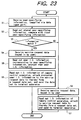
- the user-specifying information can be generated as voice pattern data.
- the user-specifying information which are supplied to the data input port 209 are generated by a voice information generating section 216 as illustrated in Fig. 20.
- this consists of a microphone input section 217 (e.g. a microphone and preamplifier circuit), which supplies electrical signals to a voice pattern processing section 218.
- the voice pattern processing section 218 generates corresponding voice pattern data, while voice pattern data of an authorized user are held stored, as user-specifying information, in the identification information storage section 206.
- the remote control apparatus is capable of registering such voice pattern data of an authorized user beforehand, as described for the case of fingerprint recognition. In this case, to achieve recognition of an authorized user, the user must speak into the microphone input section 217, and the resultant voice pattern data are then compared with the stored voice pattern data.
- Fig. 21 is a flow diagram of an example of the processing which is executed by the CPU 203 of a remote control apparatus of this embodiment to perform the operation described above, for the case in which the user identifier information is attached directly to the service request data, in a request data set, i.e. without encryption.
- Fig. 22 is a corresponding flow diagram of the processing executed by the CPU 312 of a corresponding terminal apparatus of this embodiment.
- each remote control apparatus can be utilized by both authorized and non-authorized users. If a non-authorized user inputs a service request, then the remote control apparatus generates and transmits a corresponding request data set, however that data set does not include the user identifier information. When such a request data set is received by the center apparatus, the center apparatus will provide only those services which are available to non-authorized users.
- each remote control apparatus or some specific remote control apparatuses, are reserved for the use of only a particular authorized user.
- any service request which is input to the remote control apparatus will not result in transmission of a request data set.
- this could readily be accomplished by a simple modification, e.g. whereby the steps S6 and S7 in the flow diagram of Fig. 21 are omitted, so that any data which are keyed in by an unauthorized user is, in effect, ignored by the remote control apparatus.
- Fig. 23 is a flow diagram of an example of the processing which is executed by the CPU 203 of a remote control apparatus of this embodiment to perform the operation described above, for the case in which the user identifier information is encrypted before being attached to the service request data, in a request data set, to be subsequently decrypted when received by the terminal apparatus, while Fig. 24 is a corresponding flow diagram of the processing executed by the CPU 312 of the corresponding terminal apparatus.
- the method of inputting the user-specifying information, by a user is different from the method of inputting service request data, i.e. the user-specifying information may be input via the data input port 209 of FIg.
- Fig. 25 is a flow diagram of an example of the processing which is executed by the CPU 203 of a remote control apparatus of this embodiment to perform the operation described above, for the case in which the user must input a password to be recognized as an authorized user, while Fig. 26 is a corresponding flow diagram of the processing executed by the CPU 312 of the corresponding terminal apparatus.
- the terminal apparatus confirms that the received user identifier information matches that of a registered user, i.e. confirms that identifier information for that specific individual has been registered at the terminal apparatus, as a user who is authorized to receive certain specific services.
- identifier information rather than user identifier information being employed as described above, one or more items of personal attribute information could be stored in each remote control apparatus in correspondence with the user-specifying information of the corresponding user.
- the age of the user could be stored in the identification information storage section 206 of Fig. 17.
- the terminal apparatus can store information which relates a certain category of user (e.g. all users who are 18 years of age or higher) to specific services which are available only to such users. This could be readily accomplished by slightly modifying the flow diagrams described above, for example by changing the steps S2, S3, S4 in Fig. 22 to become respectively:
- each remote control apparatus could store a set of personal attribute information items (as described for the first embodiment hereinabove) relating to a specific user, all of which could be attached and sent with a service request, as a request data set, when the requesting user has been recognized by the remote control apparatus.
- the terminal apparatus can selectively utilize those personal attribute information items which may be necessary for determining whether a particular service can be provided to the user.
- a fourth embodiment of the invention will be described whereby service request data can be input by scanning data which are printed in bar code form, on printed pages.
- This embodiment differs from the third embodiment described above only with respect to the configuration of each remote control apparatus, as shown in Fig. 27.
- this includes a bar code scanning section 220, i.e. a combination of an optical bar code scanning device and a suitable interface circuit for converting the resultant signals to digital data, and an input data temporary storage section 219.
- Data which are read in by bar code scanning and set into the input data temporary storage section 219 can be supplied via the data input port 209 to the CPU 203, to be then converted to suitable form for supply to the LCD display section 201 of the remote control apparatus, and displayed to the user.
- the user can thereby confirm that the correct information has been obtained by bar code scanning, and can then actuate a predetermined key of the key input section 208 (e.g. an "enter" key), causing the CPU 203 to generate a corresponding request data set as described above for the second and third embodiments, and send that to the center apparatus via the corresponding terminal apparatus.
- a predetermined key of the key input section 208 e.g. an "enter” key
- Fig. 28 is a flow diagram of an example of the processing which is executed by the CPU 203 of a remote control apparatus of this embodiment to perform the operation described above, i.e. whereby the user inputs service request data by utilizing bar code scanning.
- a user may wish to send a large number of different service requests to the system, e.g. a number of requests to purchase various different articles. In that case it is inefficient, with respect to system utilization, for separate data transfer operation to be executed from the terminal apparatus to the center apparatus in response to each of these successive requests.
- this can be configured such that successive items of information which are input by successive bar code scanning operation are stored in the input data temporary storage section 219, until the user has completed selecting the various items.
- the user can then actuate the aforementioned predetermined key, or perform some other action which indicates to the remote control apparatus that bar code item selection has been completed, whereupon a request data set will be generated which consists of the entire set of selected items, i.e. entire set of service request data items, with the remote control apparatus identifier and user identifier information attached thereto, and this request data set will be transmitted via the terminal apparatus to the center apparatus.
- the various service request items will then be handled sequentially by the center apparatus. By sending all of the selected service requests together in this way, efficient use of the CATV network is achieved.
- Fig. 29 is a flow diagram of an example of the processing which is executed by the CPU 203 of a remote control apparatus of this embodiment to perform the operation described above, i.e. whereby the user inputs service request data by utilizing bar code scanning, but whereby a plurality of service request data items can be accumulated and then sent together to the center apparatus.
- each such data item might correspond to information necessary for requesting the purchase of a specific article.
- the user can then designate one or more of these data items to be sent (i.e. as service request data) to the center apparatus, as described for the preceding embodiments.
- service request data i.e. as service request data
- each item in the menu thus displayed may be shown beside a specific numeral, in which case it can be arranged that a user can select a menu item by inputting the appropriate number, using the key input section 208.
- Fig. 30 is a flow diagram of an example of the processing which is executed by the CPU 203 of a remote control apparatus of this embodiment to perform the operation described above, i.e. whereby the user inputs data items by utilizing bar code scanning, but whereby a plurality of data items can be accumulated and then displayed to the user in the form of a menu, from which the user can select one or more data items to be sent as service request data via the corresponding terminal apparatus to the center apparatus.
- Fig. 31 shows an example of the processing executed by the CPU of a remote control apparatus in an interactive television system according to this embodiment
- Fig. 32 shows the corresponding processing which is executed by the CPU of a terminal apparatus of this embodiment
- Fig. 33 shows the corresponding processing which is executed by the CPU of the center apparatus.
- the center apparatus holds stored in memory a list of registered remote control apparatus identifiers, i.e. identifiers of of remote control apparatuses which are respectively assigned to authorized users, and also has service status data stored in memory, which specifies those services which are restricted to being accessed only by registered users, i.e. ie. a corresponding list of services which are available only to authorized users. It can thereby be ensured that a request from a user for a service will only be responded to by the center apparatus if the service is not restricted, or if the service is restricted but the remote control apparatus identifier of the user is listed as that of an authorized user.
- a specific example of using such a system would be in a hotel, in which a center apparatus can be controlled by hotel staff, e.g. at the front desk, while the terminal apparatuses are installed in respective rooms of the hotel.
- identifier numbers could be assigned to the remote control apparatuses which are identical to the numbers of the respective rooms in which they are located.
- the hotel staff can easily prevent undesirable services (i.e. entertainment programs or films) from being provided to the hotel guests who are occupying the respective rooms.
- each terminal apparatus holds stored in memory a list of remote control apparatus identifiers of remote control apparatuses which are respectively assigned to authorized users, and a corresponding list of services which are restricted to only authorized users.
- the corresponding terminal apparatus will only permit the resultant service data (sent from the center apparatus) to be displayed and made audible by the display apparatus of that terminal apparatus if the service is not restricted, or if the service is restricted but the remote control apparatus identifier of the user is listed as that of an authorized user.
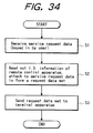
- Fig. 34 shows the processing executed by the CPU of a remote control apparatus in an interactive television system according to such an embodiment
- Fig. 35 shows the corresponding processing which is executed by the CPU of a terminal apparatus of this embodiment
- Fig. 36 shows the corresponding processing which is executed by the CPU of the center apparatus.
- a restricted service is prevented from being provided to an unregistered user by the action of the terminal apparatus in inhibiting supply of video/audio data or signals to the corresponding display apparatus.
- the terminal apparatus could simply omit to send a request data set to the center apparatus, if the request is for a restricted service, requested by an unregistered user.
- the center apparatus holds service status data stored in memory, indicating those services which are restricted to being available only to registered users.
- a service request is received by the center apparatus, i.e. a request data set is received as described for the preceding embodiments, the center apparatus checks to find if the requested service is a restricted service.
- the center apparatus superimposes a special code, which will be referred to as a restriction code, on the service data which are sent from the center apparatus to the terminal apparatus of the requesting user. If the terminal apparatus detects the presence of this restriction code in the received service data, then determines whether the requesting user is authorized to receive that service. If the user is not authorized, i.e. is not a registered user, then the terminal apparatus inhibits the service data from being displayed or made audible by the display apparatus.
- a restriction code which will be referred to as a restriction code
- the identification of a user by as being authorized, by a terminal apparatus can be performed based on the remote control apparatus identifier of the remote control apparatus employed by the user, or based on user identifier information which is supplied when the user has been recognized by the remote control apparatus (i.e. in response to input of a password code, fingerprint recognition, or voice pattern recognition, as described above).
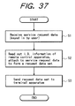
- Fig. 37 is a flow diagram of an example of the processing executed by the CPU of a remote control apparatus in an interactive television system according to such an embodiment, assuming that each message data set, i.e. each service request data set, consists only of the service request data with the identifier of the originating remote control apparatus attached thereto.
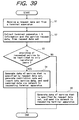
- Figs. 38A, 38B constitute a flow diagram of the corresponding processing which is executed by the CPU of a terminal apparatus of this embodiment, while Fig. 39 shows the corresponding processing which is executed by the CPU of the center apparatus.
- each response data set which is sent from a remote control apparatus could be reliably identified by the user as originating from a specific user, or a member of a specific class of user, in spite of the fact that each remote control apparatus need not be exclusively assigned to the user of a specific user.
- the identifiers assigned to the remote control apparatuses and to the terminal apparatuses are respectively unique within the system, while the center apparatus holds information which relates the remote control apparatus identifiers to their respective terminal apparatus identifiers. In that case, it is unnecessary for the terminal apparatus identifier to be attached to data which are sent from a remote control apparatus via its terminal apparatus to the center apparatus.
- the center apparatus must store information relating each remote control apparatus identifier to the identifier of the corresponding terminal apparatus. Such an arrangement is assumed in the various embodiments of the invention described hereinafter.
- the invention is applicable to a multi-level arrangement for classifying users. That is to say, certain individual users, or a certain category of users, might be registered by the system as being permitted to access a specific set of services, while other users or another category of users would be registered as being permitted to access a different set of services.
- the center apparatus or each terminal apparatus
- the operation of the system in such a case could easily be envisaged, by extension from the descriptions of embodiments provided hereinabove. In that way it would be possible to provide a plurality of different levels of service which are intended for respectively different users of the system.
Applications Claiming Priority (6)
| Application Number | Priority Date | Filing Date | Title |
|---|---|---|---|
| JP307081/95 | 1995-11-27 | ||
| JP30708295 | 1995-11-27 | ||
| JP307082/95 | 1995-11-27 | ||
| JP7307082A JPH09149392A (ja) | 1995-11-27 | 1995-11-27 | 対話型tvシステム |
| JP30708195A JPH09147029A (ja) | 1995-11-27 | 1995-11-27 | 電子投票システム |
| JP30708195 | 1995-11-27 |
Publications (3)
| Publication Number | Publication Date |
|---|---|
| EP0776132A2 true EP0776132A2 (fr) | 1997-05-28 |
| EP0776132A3 EP0776132A3 (fr) | 1997-11-19 |
| EP0776132B1 EP0776132B1 (fr) | 2002-02-06 |
Family
ID=26564968
Family Applications (1)
| Application Number | Title | Priority Date | Filing Date |
|---|---|---|---|
| EP96308572A Expired - Lifetime EP0776132B1 (fr) | 1995-11-27 | 1996-11-27 | Système interactif de télévision |
Country Status (3)
| Country | Link |
|---|---|
| US (1) | US5721583A (fr) |
| EP (1) | EP0776132B1 (fr) |
| DE (2) | DE69619073T4 (fr) |
Cited By (16)
| Publication number | Priority date | Publication date | Assignee | Title |
|---|---|---|---|---|
| EP0910215A2 (fr) * | 1997-10-14 | 1999-04-21 | GRUNDIG Aktiengesellschaft | Circuit de libération de programmes pour l'électronique grand public et/ou la technique de communication |
| EP0954179A2 (fr) * | 1998-04-30 | 1999-11-03 | Wink Communications, Inc. | Gestion de capacité de réponse dans un système de télédiffusion interactif |
| EP1111911A1 (fr) * | 1999-12-21 | 2001-06-27 | Grundig AG | Dispositif pour la télécommande d'un récepteur de télévision ou d'un enregistreur vidéo |
| WO2002028018A2 (fr) * | 2000-09-26 | 2002-04-04 | The Musicbooth, Llc. | Procede et appareil permettant d'identifier les caracteristiques d'un utilisateur et d'un dispositif au moyen d'un reseau de communication |
| DE10103948A1 (de) * | 2001-01-30 | 2002-08-01 | Bsh Bosch Siemens Hausgeraete | Verfahren und Vorrichtung zur Steuerung von Hausgeräten |
| US6477508B1 (en) * | 1997-10-09 | 2002-11-05 | Clifford W. Lazar | System and apparatus for broadcasting, capturing, storing, selecting and then forwarding selected product data and viewer choices to vendor host computers |
| EP1308865A1 (fr) * | 2000-08-10 | 2003-05-07 | NTT DoCoMo, Inc. | Procede d'utilisation d'emission, recepteur, terminal mobile et dispositif prestataire de services |
| US6804357B1 (en) | 2000-04-28 | 2004-10-12 | Nokia Corporation | Method and system for providing secure subscriber content data |
| WO2005015844A1 (fr) * | 2003-08-08 | 2005-02-17 | Intel Corporation | Interrogations d'apprentissage en acces multiple par repartition spatiale en multidiffusion |
| FR2881553A1 (fr) * | 2005-02-01 | 2006-08-04 | Awox Sa | Procede et dispositif de telecommande |
| US7451401B2 (en) | 1999-05-28 | 2008-11-11 | Nokia Corporation | Real-time, interactive and personalized video services |
| FR2930357A1 (fr) * | 2008-04-17 | 2009-10-23 | Alcatel Lucent Sas | Procede de vote electronique,decodeur pour la mise en oeuvre de ce procede et reseau comprenant un serveur de vote pour la mise en oeuvre du procede. |
| WO2010030737A1 (fr) * | 2008-09-10 | 2010-03-18 | Qualcomm Incorporated | Procédés et systèmes pour permettre une interactivité dans un réseau de diffusion vers les mobiles |
| WO2010030734A1 (fr) * | 2008-09-10 | 2010-03-18 | Qualcomm Incorporated | Procédés et systèmes de diffusion de contenu sur la base d'entrée d'utilisateur |
| US8699508B2 (en) | 2003-12-18 | 2014-04-15 | Intel Corporation | Response scheduling for multiple receivers |
| US9325953B2 (en) | 2011-02-14 | 2016-04-26 | Disney Enterprises, Inc. | System and method for synchronizing on-air commercial programming with interactive applications |
Families Citing this family (155)
| Publication number | Priority date | Publication date | Assignee | Title |
|---|---|---|---|---|
| US7188352B2 (en) * | 1995-07-11 | 2007-03-06 | Touchtunes Music Corporation | Intelligent digital audiovisual playback system |
| EP0786121B1 (fr) | 1994-10-12 | 2000-01-12 | Touchtunes Music Corporation | Systeme de reproduction audio-visuelle numerique intelligent |
| US7424731B1 (en) * | 1994-10-12 | 2008-09-09 | Touchtunes Music Corporation | Home digital audiovisual information recording and playback system |
| US8661477B2 (en) * | 1994-10-12 | 2014-02-25 | Touchtunes Music Corporation | System for distributing and selecting audio and video information and method implemented by said system |
| US6675384B1 (en) * | 1995-12-21 | 2004-01-06 | Robert S. Block | Method and apparatus for information labeling and control |
| US6035403A (en) * | 1996-09-11 | 2000-03-07 | Hush, Inc. | Biometric based method for software distribution |
| JPH1097414A (ja) * | 1996-09-19 | 1998-04-14 | Toshiba Corp | 携帯型情報機器およびプログラム起動制御方法 |
| FR2753868A1 (fr) * | 1996-09-25 | 1998-03-27 | Technical Maintenance Corp | Procede de selection d'un enregistrement sur un systeme numerique de reproduction audiovisuel et systeme pour mise en oeuvre du procede |
| KR100188658B1 (ko) * | 1996-09-30 | 1999-06-01 | 윤종용 | 복합 기능의 리모콘 및 그에 의한 복합 제품의제어 방법 |
| JP3658896B2 (ja) | 1996-11-26 | 2005-06-08 | ソニー株式会社 | 情報信号伝送システム、再生装置及び表示装置 |
| NL1006042C2 (nl) * | 1997-05-13 | 1998-11-16 | Verify International N V | Methode en inrichting voor het testen van audio-visuele stimuli. |
| FR2769165B1 (fr) | 1997-09-26 | 2002-11-29 | Technical Maintenance Corp | Systeme sans fil a transmission numerique pour haut-parleurs |
| US6757001B2 (en) | 1999-03-30 | 2004-06-29 | Research Investment Network, Inc. | Method of using physical buttons in association with a display to access and execute functions available through associated hardware and software |
| US20020055906A1 (en) * | 1998-03-11 | 2002-05-09 | Katz Ronald A. | Methods and apparatus for intelligent selection of goods and services in telephonic and electronic commerce |
| US7364068B1 (en) | 1998-03-11 | 2008-04-29 | West Corporation | Methods and apparatus for intelligent selection of goods and services offered to conferees |
| US7437313B1 (en) | 1998-03-11 | 2008-10-14 | West Direct, Llc | Methods, computer-readable media, and apparatus for offering users a plurality of scenarios under which to conduct at least one primary transaction |
| US6289346B1 (en) * | 1998-03-12 | 2001-09-11 | At&T Corp. | Apparatus and method for a bookmarking system |
| IL127790A (en) * | 1998-04-21 | 2003-02-12 | Ibm | System and method for selecting, accessing and viewing portions of an information stream(s) using a television companion device |
| IL127791A (en) * | 1998-04-21 | 2003-06-24 | Ibm | System and method for selecting and accessing portions of information stream(s) from a television |
| JP3863574B2 (ja) * | 1998-05-20 | 2006-12-27 | 松下電器産業株式会社 | 制御システム、制御装置および被制御装置 |
| EP0963115A1 (fr) * | 1998-06-05 | 1999-12-08 | THOMSON multimedia | Appareil et méthode pour la sélection du profil du téléspectateur dans un système de télévision interactive |
| FR2781582B1 (fr) * | 1998-07-21 | 2001-01-12 | Technical Maintenance Corp | Systeme de telechargement d'objets ou de fichiers pour mise a jour de logiciels |
| US8028318B2 (en) * | 1999-07-21 | 2011-09-27 | Touchtunes Music Corporation | Remote control unit for activating and deactivating means for payment and for displaying payment status |
| FR2781591B1 (fr) | 1998-07-22 | 2000-09-22 | Technical Maintenance Corp | Systeme de reproduction audiovisuelle |
| FR2781593B1 (fr) * | 1998-07-22 | 2001-01-12 | Technical Maintenance Corp | Telecommande pour systeme de reproduction audiovisuelle numerique intelligent |
| FR2781580B1 (fr) | 1998-07-22 | 2000-09-22 | Technical Maintenance Corp | Circuit de commande de son pour systeme de reproduction audiovisuelle numerique intelligent |
| US6317881B1 (en) * | 1998-11-04 | 2001-11-13 | Intel Corporation | Method and apparatus for collecting and providing viewer feedback to a broadcast |
| US6381347B1 (en) * | 1998-11-12 | 2002-04-30 | Secugen | High contrast, low distortion optical acquistion system for image capturing |
| US6269479B1 (en) * | 1998-11-30 | 2001-07-31 | Unisys Corporation | Method and computer program product for evaluating the performance of an object-oriented application program |
| US8726330B2 (en) * | 1999-02-22 | 2014-05-13 | Touchtunes Music Corporation | Intelligent digital audiovisual playback system |
| US6256019B1 (en) | 1999-03-30 | 2001-07-03 | Eremote, Inc. | Methods of using a controller for controlling multi-user access to the functionality of consumer devices |
| JP4378576B2 (ja) * | 1999-05-18 | 2009-12-09 | ソニー株式会社 | 受信装置および方法、供給装置および方法、双方向通信システムおよび方法、並びに記録媒体 |
| US6438752B1 (en) * | 1999-06-22 | 2002-08-20 | Mediaone Group, Inc. | Method and system for selecting television programs based on the past selection history of an identified user |
| US6543052B1 (en) * | 1999-07-09 | 2003-04-01 | Fujitsu Limited | Internet shopping system utilizing set top box and voice recognition |
| US7568208B1 (en) | 1999-07-14 | 2009-07-28 | Thomson Licensing | Method and apparatus for using a single password set in an integrated television system |
| FR2796482B1 (fr) | 1999-07-16 | 2002-09-06 | Touchtunes Music Corp | Systeme de gestion a distance d'au moins un dispositif de reproduction d'informations audiovisuelles |
| US6608919B1 (en) * | 1999-11-10 | 2003-08-19 | Digimarc Corporation | Method and apparatus for encoding paper with information |
| AU2001234456A1 (en) * | 2000-01-13 | 2001-07-24 | Erinmedia, Inc. | Privacy compliant multiple dataset correlation system |
| US7146329B2 (en) * | 2000-01-13 | 2006-12-05 | Erinmedia, Llc | Privacy compliant multiple dataset correlation and content delivery system and methods |
| JP4846890B2 (ja) * | 2000-01-20 | 2011-12-28 | ソニー株式会社 | 端末制御装置 |
| FR2805377B1 (fr) | 2000-02-23 | 2003-09-12 | Touchtunes Music Corp | Procede de commande anticipee d'une selection, systeme numerique et juke-box permettant la mise en oeuvre du procede |
| FR2805072B1 (fr) | 2000-02-16 | 2002-04-05 | Touchtunes Music Corp | Procede d'ajustement du volume sonore d'un enregistrement sonore numerique |
| FR2805060B1 (fr) | 2000-02-16 | 2005-04-08 | Touchtunes Music Corp | Procede de reception de fichiers lors d'un telechargement |
| US7284064B1 (en) * | 2000-03-21 | 2007-10-16 | Intel Corporation | Method and apparatus to determine broadcast content and scheduling in a broadcast system |
| FR2808906B1 (fr) | 2000-05-10 | 2005-02-11 | Touchtunes Music Corp | Dispositif et procede de gestion a distance d'un reseau de systemes de reproduction d'informations audiovisuelles |
| US6565084B1 (en) * | 2000-06-02 | 2003-05-20 | Milestone Entertainment | Games, and methods for improved game play in games of chance and games of skill |
| US10173128B2 (en) | 2000-06-02 | 2019-01-08 | Milestone Entertainment Llc | Games, and methods for improved game play in games of chance and games of skill |
| FR2811175B1 (fr) | 2000-06-29 | 2002-12-27 | Touchtunes Music Corp | Procede de distribution d'informations audiovisuelles et systeme de distribution d'informations audiovisuelles |
| FR2811114B1 (fr) | 2000-06-29 | 2002-12-27 | Touchtunes Music Corp | Dispositif et procede de communication entre un systeme de reproduction d'informations audiovisuelles et d'une machine electronique de divertissement |
| USRE47053E1 (en) * | 2000-06-30 | 2018-09-18 | Benhov Gmbh, Llc | Method and system for subscriber-based audio service over a communication network |
| US6662231B1 (en) * | 2000-06-30 | 2003-12-09 | Sei Information Technology | Method and system for subscriber-based audio service over a communication network |
| US6918131B1 (en) * | 2000-07-10 | 2005-07-12 | Nokia Corporation | Systems and methods for characterizing television preferences over a wireless network |
| JP3806087B2 (ja) * | 2000-07-18 | 2006-08-09 | 株式会社エヌ・ティ・ティ・ドコモ | 番組提供システム |
| KR100466563B1 (ko) * | 2000-07-26 | 2005-01-14 | 엔티티 도꼬모 인코퍼레이티드 | 시청률 산출 시스템 및 이동통신단말 |
| AU2001279170A1 (en) * | 2000-08-03 | 2002-02-18 | Edwin L. Lyda | Apparatus for remote learning system |
| WO2002021877A1 (fr) * | 2000-09-08 | 2002-03-14 | Fujitsu Limited | Dispositif de telecommande |
| FR2814085B1 (fr) | 2000-09-15 | 2005-02-11 | Touchtunes Music Corp | Procede de divertissement base sur les jeux concours a choix multiples |
| US6811484B2 (en) * | 2001-09-26 | 2004-11-02 | Milestone Entertainment Llc | Games, and methods and apparatus for game play in games of chance |
| US6488280B1 (en) * | 2000-09-27 | 2002-12-03 | Milestone Entertainment | Games, and methods and apparatus for game play in games of chance |
| US8393946B2 (en) | 2001-09-26 | 2013-03-12 | Milestone Entertainment Llc | Apparatus and method for game play in an electronic environment |
| US7798896B2 (en) * | 2000-09-27 | 2010-09-21 | Milestone Entertainment Llc | Apparatus, systems and methods for implementing enhanced gaming and prizing parameters in an electronic environment |
| US8727853B2 (en) | 2000-09-27 | 2014-05-20 | Milestone Entertainment, LLC | Methods and apparatus for enhanced play in lottery and gaming environments |
| US20060253330A1 (en) * | 2000-10-12 | 2006-11-09 | Maggio Frank S | Method and system for automatically substituting media content |
| US20040015399A1 (en) * | 2000-10-12 | 2004-01-22 | Maggio Frank S. | Method and system for verifying exposure to message content delivered via outdoor media or in a concentrated format |
| US20030195807A1 (en) * | 2000-10-12 | 2003-10-16 | Frank S. Maggio | Method and system for verifying exposure to message content via a printed response |
| US20060129458A1 (en) * | 2000-10-12 | 2006-06-15 | Maggio Frank S | Method and system for interacting with on-demand video content |
| US20060282319A1 (en) * | 2000-10-12 | 2006-12-14 | Maggio Frank S | Method and system for substituting media content |
| US8751957B1 (en) * | 2000-11-22 | 2014-06-10 | Pace Micro Technology Plc | Method and apparatus for obtaining auditory and gestural feedback in a recommendation system |
| JP4272810B2 (ja) * | 2000-12-26 | 2009-06-03 | キヤノン株式会社 | 放送受信装置及び放送受信装置の制御方法 |
| US6946970B2 (en) * | 2000-12-29 | 2005-09-20 | Bellsouth Intellectual Property Corp. | Remote control device with smart card capability |
| US6903655B2 (en) * | 2000-12-29 | 2005-06-07 | Bellsouth Intellectual Property Corp. | Remote control device with illumination |
| US7653926B2 (en) | 2000-12-29 | 2010-01-26 | At&T Intellectual Property I, L.P. | Remote control device with event notifier |
| JP3644502B2 (ja) * | 2001-02-06 | 2005-04-27 | ソニー株式会社 | コンテンツ受信装置およびコンテンツ呈示制御方法 |
| US8543823B2 (en) * | 2001-04-30 | 2013-09-24 | Digimarc Corporation | Digital watermarking for identification documents |
| KR20030097847A (ko) * | 2001-05-02 | 2003-12-31 | 시큐젠 코포레이션 | 컴퓨터 네트워크상에서 사용자를 생체인증하는 방법 |
| KR20020028754A (ko) * | 2001-05-04 | 2002-04-17 | 안준영 | 액정표시겸 지문입력 패널 |
| US20030005451A1 (en) * | 2001-06-15 | 2003-01-02 | Connelly Jay H. | Method and apparatus to distribute content descriptors in a content distribution broadcast system |
| KR100432490B1 (ko) * | 2001-09-17 | 2004-05-22 | (주)니트 젠 | 광학식 지문취득 장치 |
| US9626837B2 (en) | 2001-09-26 | 2017-04-18 | Milestone Entertainment Llc | System for game play in an electronic environment |
| JP2003173430A (ja) * | 2001-09-28 | 2003-06-20 | Sharp Corp | Icカード、スクランブル解除装置、サーバ装置、身体的特徴読取装置、許可者判定方法、許可者登録方法、度数管理方法、許可者判定プログラム、許可者登録プログラム、度数管理プログラム、およびそのプログラムを記録したコンピュータ読取可能な記録媒体 |
| US20030066072A1 (en) * | 2001-10-03 | 2003-04-03 | Sony Corporation | System and method for voting on TV programs |
| US20030069802A1 (en) * | 2001-10-09 | 2003-04-10 | Koninklijke Philips Electronics N.V. | Tv shopping monitor and notification system |
| US7904392B2 (en) * | 2001-10-25 | 2011-03-08 | Panasonic Corporation | Content usage rule management system |
| WO2003053060A1 (fr) * | 2001-12-17 | 2003-06-26 | Digeo, Inc. | Telecommande faisant intervenir l'utilisation d'un lecteur biometrique dans un systeme de television interactive |
| US7728048B2 (en) * | 2002-12-20 | 2010-06-01 | L-1 Secure Credentialing, Inc. | Increasing thermal conductivity of host polymer used with laser engraving methods and compositions |
| US20030147624A1 (en) * | 2002-02-06 | 2003-08-07 | Koninklijke Philips Electronics N.V. | Method and apparatus for controlling a media player based on a non-user event |
| US20030196206A1 (en) | 2002-04-15 | 2003-10-16 | Shusman Chad W. | Method and apparatus for internet-based interactive programming |
| US20040210947A1 (en) | 2003-04-15 | 2004-10-21 | Shusman Chad W. | Method and apparatus for interactive video on demand |
| US20040032486A1 (en) * | 2002-08-16 | 2004-02-19 | Shusman Chad W. | Method and apparatus for interactive programming using captioning |
| US8116889B2 (en) | 2002-06-27 | 2012-02-14 | Openpeak Inc. | Method, system, and computer program product for managing controlled residential or non-residential environments |
| US7933945B2 (en) * | 2002-06-27 | 2011-04-26 | Openpeak Inc. | Method, system, and computer program product for managing controlled residential or non-residential environments |
| JP4519645B2 (ja) * | 2002-07-12 | 2010-08-04 | プリヴァリス・インコーポレーテッド | 旅行特権割当ておよび検証用個人認証ソフトウェアおよびシステム |
| TW200415523A (en) * | 2002-08-21 | 2004-08-16 | Secugen Corp | TFT sensor having improved imaging surface |
| US8151304B2 (en) * | 2002-09-16 | 2012-04-03 | Touchtunes Music Corporation | Digital downloading jukebox system with user-tailored music management, communications, and other tools |
| US8103589B2 (en) | 2002-09-16 | 2012-01-24 | Touchtunes Music Corporation | Digital downloading jukebox system with central and local music servers |
| US8584175B2 (en) | 2002-09-16 | 2013-11-12 | Touchtunes Music Corporation | Digital downloading jukebox system with user-tailored music management, communications, and other tools |
| US10373420B2 (en) | 2002-09-16 | 2019-08-06 | Touchtunes Music Corporation | Digital downloading jukebox with enhanced communication features |
| US11029823B2 (en) | 2002-09-16 | 2021-06-08 | Touchtunes Music Corporation | Jukebox with customizable avatar |
| US7822687B2 (en) | 2002-09-16 | 2010-10-26 | Francois Brillon | Jukebox with customizable avatar |
| US9646339B2 (en) * | 2002-09-16 | 2017-05-09 | Touchtunes Music Corporation | Digital downloading jukebox system with central and local music servers |
| US8332895B2 (en) | 2002-09-16 | 2012-12-11 | Touchtunes Music Corporation | Digital downloading jukebox system with user-tailored music management, communications, and other tools |
| US20040128501A1 (en) * | 2002-09-20 | 2004-07-01 | Yohei Yamamoto | Service offering system for allowing a client having no account to access a managed object with a limited right |
| US6882729B2 (en) * | 2002-12-12 | 2005-04-19 | Universal Electronics Inc. | System and method for limiting access to data |
| US7987489B2 (en) * | 2003-01-07 | 2011-07-26 | Openpeak Inc. | Legacy device bridge for residential or non-residential networks |
| US8712857B1 (en) | 2003-03-31 | 2014-04-29 | Tuxis Technologies Llc | Methods and apparatus for intelligent selection of goods and services in mobile commerce |
| EP1614064B1 (fr) | 2003-04-16 | 2010-12-08 | L-1 Secure Credentialing, Inc. | Stockage de donnees en trois dimensions |
| WO2004099928A2 (fr) * | 2003-05-02 | 2004-11-18 | Maggio Frank S | Procede et systeme de verification d'acces au contenu d'un message delivre par des reseaux a souscription |
| JP4532988B2 (ja) * | 2003-05-28 | 2010-08-25 | キヤノン株式会社 | 操作画面の制御方法及びプログラム、並びに表示制御装置 |
| US7587611B2 (en) * | 2003-05-30 | 2009-09-08 | Privaris, Inc. | In-circuit security system and methods for controlling access to and use of sensitive data |
| KR100485136B1 (ko) * | 2003-11-21 | 2005-04-25 | 김상덕 | 디지털 셋탑 박스와 연계한 스마트 카드를 이용한 온라인전자 투표 시스템 및 그 방법 |
| KR100556438B1 (ko) * | 2004-01-02 | 2006-03-03 | 엘지전자 주식회사 | 영상기기의 원격 제어장치 및 그 제어방법 |
| US7832500B2 (en) * | 2004-03-01 | 2010-11-16 | Schlumberger Technology Corporation | Wellbore drilling method |
| US8346157B1 (en) | 2004-06-16 | 2013-01-01 | Colby Steven M | Content customization in asymmertic communication systems |
| US11875642B2 (en) | 2004-09-01 | 2024-01-16 | Milestone Entertainment, LLC | Systems for implementing enhanced gaming and prizing parameters in an electronic environment |
| US9773373B2 (en) | 2004-09-01 | 2017-09-26 | Milestone Entertainment Llc | Systems for implementing enhanced gaming and prizing parameters in an electronic environment |
| US7610011B2 (en) * | 2004-09-19 | 2009-10-27 | Adam Albrett | Providing alternative programming on a radio in response to user input |
| US7178720B1 (en) * | 2004-09-30 | 2007-02-20 | West Corporation | Methods, computer-readable media, and computer program product for intelligent selection of items encoded onto portable machine-playable entertainment media |
| US20060271437A1 (en) * | 2005-05-26 | 2006-11-30 | Maggio Frank S | System and method for home product delivery |
| JP4559943B2 (ja) * | 2005-06-24 | 2010-10-13 | 株式会社東芝 | プレイリスト作成装置、プレイリスト作成方法、プレイリスト作成プログラム、著作権情報管理装置、および視聴端末装置 |
| US20070290878A1 (en) * | 2006-04-07 | 2007-12-20 | Media Ip Holdings, Llc | System and method for interacting with automobile race and advertising content |
| US20080032277A1 (en) * | 2006-04-08 | 2008-02-07 | Media Ip Holdings, Llc | Dynamic multiple choice answers |
| JP2008085515A (ja) * | 2006-09-27 | 2008-04-10 | Hitachi Ltd | コンテンツ受信端末システム及びコンテンツ受信端末装置 |
| US8241100B2 (en) | 2006-10-11 | 2012-08-14 | Milestone Entertainment Llc | Methods and apparatus for enhanced interactive game play in lottery and gaming environments |
| US9508225B2 (en) | 2006-10-11 | 2016-11-29 | Milestone Entertainment Llc | Methods and apparatus for enhanced interactive game play in lottery and gaming environments |
| US9171419B2 (en) | 2007-01-17 | 2015-10-27 | Touchtunes Music Corporation | Coin operated entertainment system |
| US9330529B2 (en) * | 2007-01-17 | 2016-05-03 | Touchtunes Music Corporation | Game terminal configured for interaction with jukebox device systems including same, and/or associated methods |
| US9953481B2 (en) * | 2007-03-26 | 2018-04-24 | Touchtunes Music Corporation | Jukebox with associated video server |
| US8620878B2 (en) * | 2007-07-19 | 2013-12-31 | Ustream, Inc. | System and method of distributing multimedia content |
| JP4636058B2 (ja) * | 2007-08-08 | 2011-02-23 | コニカミノルタビジネステクノロジーズ株式会社 | 会議システム、データ処理装置、データ出力方法およびデータ出力プログラム |
| US8332887B2 (en) | 2008-01-10 | 2012-12-11 | Touchtunes Music Corporation | System and/or methods for distributing advertisements from a central advertisement network to a peripheral device via a local advertisement server |
| US10290006B2 (en) | 2008-08-15 | 2019-05-14 | Touchtunes Music Corporation | Digital signage and gaming services to comply with federal and state alcohol and beverage laws and regulations |
| US8535134B2 (en) | 2008-01-28 | 2013-09-17 | Milestone Entertainment Llc | Method and system for electronic interaction in a multi-player gaming system |
| US8194827B2 (en) | 2008-04-29 | 2012-06-05 | International Business Machines Corporation | Secure voice transaction method and system |
| US8849435B2 (en) | 2008-07-09 | 2014-09-30 | Touchtunes Music Corporation | Digital downloading jukebox with revenue-enhancing features |
| ES2370740T3 (es) * | 2008-07-21 | 2011-12-22 | Somfy Sas | Método para controlar un grupo de aparatos controlados de forma inalámbrica. |
| US20100050270A1 (en) * | 2008-08-20 | 2010-02-25 | AT&T InteIlectual Property I, L.P. | Control of Access to Content Received from a Multimedia Content Distribution Network |
| US8362875B2 (en) * | 2008-09-24 | 2013-01-29 | Panasonic Corporation | Secure system for non-covert user authentication and identification |
| KR101615763B1 (ko) * | 2008-10-09 | 2016-04-27 | 삼성전자주식회사 | 가시광 통신을 이용한 영상 부가정보 운영방법 및 이를 위한 장치 |
| CA2754990C (fr) | 2009-03-18 | 2015-07-14 | Touchtunes Music Corporation | Serveur de divertissement et services de reseau social associes |
| US10719149B2 (en) | 2009-03-18 | 2020-07-21 | Touchtunes Music Corporation | Digital jukebox device with improved user interfaces, and associated methods |
| US9292166B2 (en) | 2009-03-18 | 2016-03-22 | Touchtunes Music Corporation | Digital jukebox device with improved karaoke-related user interfaces, and associated methods |
| US10564804B2 (en) | 2009-03-18 | 2020-02-18 | Touchtunes Music Corporation | Digital jukebox device with improved user interfaces, and associated methods |
| CN101621657B (zh) * | 2009-08-06 | 2011-01-19 | 中兴通讯股份有限公司 | 无线视频会议系统及其投票方法 |
| US20110067044A1 (en) * | 2009-09-14 | 2011-03-17 | Albo Robert W | Interactive platform for broadcast programs |
| WO2011062883A1 (fr) * | 2009-11-20 | 2011-05-26 | Ustream, Inc. | Notifications de diffusion au moyen de systèmes de réseau social |
| US8627379B2 (en) * | 2010-01-07 | 2014-01-07 | Amazon Technologies, Inc. | Offering items identified in a media stream |
| CN105355221A (zh) | 2010-01-26 | 2016-02-24 | 踏途音乐公司 | 具有改进的用户界面的数字点播设备和相关方法 |
| US10248937B2 (en) | 2010-11-19 | 2019-04-02 | At&T Intellectual Property I, L.P. | System and method of providing post-purchase media content to a subscriber |
| JP6002770B2 (ja) | 2011-09-18 | 2016-10-05 | タッチチューンズ ミュージック コーポレーション | カラオケおよび/またはプリクラ機能を備えたデジタルジュークボックス装置および関連手法 |
| US11151224B2 (en) | 2012-01-09 | 2021-10-19 | Touchtunes Music Corporation | Systems and/or methods for monitoring audio inputs to jukebox devices |
| TW201427404A (zh) * | 2012-12-26 | 2014-07-01 | Hon Hai Prec Ind Co Ltd | 電視機控制系統及方法 |
| WO2015025235A1 (fr) * | 2013-08-23 | 2015-02-26 | Koninklijke Philips N.V. | Commande d'un système d'éclairage |
| US9921717B2 (en) | 2013-11-07 | 2018-03-20 | Touchtunes Music Corporation | Techniques for generating electronic menu graphical user interface layouts for use in connection with electronic devices |
| KR102303730B1 (ko) | 2014-03-25 | 2021-09-17 | 터치튠즈 뮤직 코포레이션 | 향상된 사용자 인터페이스를 가지는 디지털 주크박스 장치 및 관련 방법. |
| US11102632B2 (en) * | 2019-10-09 | 2021-08-24 | Nokia Technologies Oy | Access mechanism for single purpose operation |
Citations (7)
| Publication number | Priority date | Publication date | Assignee | Title |
|---|---|---|---|---|
| JPH01311364A (ja) * | 1988-06-10 | 1989-12-15 | Sanyo Electric Co Ltd | 注文管理装置 |
| GB2256515A (en) * | 1991-06-06 | 1992-12-09 | * Norm Pacific Automation Corporation | Interactive remote control |
| FR2696888A1 (fr) * | 1992-10-12 | 1994-04-15 | Morgaine Sylvain | Système de boîtier communicant à écran tactile, intégrant une carte à mémoire qui définit sa fonctionnalité. |
| WO1994014280A1 (fr) * | 1992-12-09 | 1994-06-23 | Discovery Communications, Inc. | Unite de commande de reseau pour systemes de diffusion de programmes de television par cable |
| WO1995001057A1 (fr) * | 1993-06-22 | 1995-01-05 | Apple Computer, Inc. | Procede et appareil pour gerer la visualisation d'offres de programmes et de services audiovisuels et pour gerer l'interaction de l'utilisateur avec ces offres |
| WO1995028799A1 (fr) * | 1994-04-19 | 1995-10-26 | Scientific-Atlanta, Inc. | Procede et dispositif de realisation d'un guide de programmation electronique interactive |
| DE19520180A1 (de) * | 1994-11-09 | 1996-05-15 | Cis Hotel Communications Gmbh | Fernbedienung für ein Empfangsgerät |
Family Cites Families (7)
| Publication number | Priority date | Publication date | Assignee | Title |
|---|---|---|---|---|
| US4566030A (en) * | 1983-06-09 | 1986-01-21 | Ctba Associates | Television viewer data collection system |
| JPS62258541A (ja) * | 1986-05-02 | 1987-11-11 | Nec Corp | 視聴者情報収集システム |
| US4930011A (en) * | 1988-08-02 | 1990-05-29 | A. C. Nielsen Company | Method and apparatus for identifying individual members of a marketing and viewing audience |
| US5155591A (en) * | 1989-10-23 | 1992-10-13 | General Instrument Corporation | Method and apparatus for providing demographically targeted television commercials |
| US5497185A (en) * | 1991-04-25 | 1996-03-05 | Le Groupe Videotron Ltee. | Remote control system for television audience data gathering |
| US5734413A (en) * | 1991-11-20 | 1998-03-31 | Thomson Multimedia S.A. | Transaction based interactive television system |
| JPH05250080A (ja) * | 1992-03-05 | 1993-09-28 | Canon Inc | データ入力装置および再生装置および記録または再生装置 |
-
1996
- 1996-11-26 US US08/756,773 patent/US5721583A/en not_active Expired - Fee Related
- 1996-11-27 DE DE69619073T patent/DE69619073T4/de not_active Expired - Lifetime
- 1996-11-27 EP EP96308572A patent/EP0776132B1/fr not_active Expired - Lifetime
- 1996-11-27 DE DE69619073A patent/DE69619073D1/de not_active Expired - Fee Related
Patent Citations (7)
| Publication number | Priority date | Publication date | Assignee | Title |
|---|---|---|---|---|
| JPH01311364A (ja) * | 1988-06-10 | 1989-12-15 | Sanyo Electric Co Ltd | 注文管理装置 |
| GB2256515A (en) * | 1991-06-06 | 1992-12-09 | * Norm Pacific Automation Corporation | Interactive remote control |
| FR2696888A1 (fr) * | 1992-10-12 | 1994-04-15 | Morgaine Sylvain | Système de boîtier communicant à écran tactile, intégrant une carte à mémoire qui définit sa fonctionnalité. |
| WO1994014280A1 (fr) * | 1992-12-09 | 1994-06-23 | Discovery Communications, Inc. | Unite de commande de reseau pour systemes de diffusion de programmes de television par cable |
| WO1995001057A1 (fr) * | 1993-06-22 | 1995-01-05 | Apple Computer, Inc. | Procede et appareil pour gerer la visualisation d'offres de programmes et de services audiovisuels et pour gerer l'interaction de l'utilisateur avec ces offres |
| WO1995028799A1 (fr) * | 1994-04-19 | 1995-10-26 | Scientific-Atlanta, Inc. | Procede et dispositif de realisation d'un guide de programmation electronique interactive |
| DE19520180A1 (de) * | 1994-11-09 | 1996-05-15 | Cis Hotel Communications Gmbh | Fernbedienung für ein Empfangsgerät |
Non-Patent Citations (1)
| Title |
|---|
| PATENT ABSTRACTS OF JAPAN vol. 014, no. 114 (P-1015), 2 March 1990 & JP 01 311364 A (SANYO ELECTRIC CO LTD), 15 December 1989, * |
Cited By (26)
| Publication number | Priority date | Publication date | Assignee | Title |
|---|---|---|---|---|
| US6477508B1 (en) * | 1997-10-09 | 2002-11-05 | Clifford W. Lazar | System and apparatus for broadcasting, capturing, storing, selecting and then forwarding selected product data and viewer choices to vendor host computers |
| EP0910215A3 (fr) * | 1997-10-14 | 2000-01-19 | GRUNDIG Aktiengesellschaft | Circuit de libération de programmes pour l'électronique grand public et/ou la technique de communication |
| EP0910215A2 (fr) * | 1997-10-14 | 1999-04-21 | GRUNDIG Aktiengesellschaft | Circuit de libération de programmes pour l'électronique grand public et/ou la technique de communication |
| EP0954179A2 (fr) * | 1998-04-30 | 1999-11-03 | Wink Communications, Inc. | Gestion de capacité de réponse dans un système de télédiffusion interactif |
| EP0954179A3 (fr) * | 1998-04-30 | 2001-01-03 | Wink Communications, Inc. | Gestion de capacité de réponse dans un système de télédiffusion interactif |
| US7451401B2 (en) | 1999-05-28 | 2008-11-11 | Nokia Corporation | Real-time, interactive and personalized video services |
| EP1111911A1 (fr) * | 1999-12-21 | 2001-06-27 | Grundig AG | Dispositif pour la télécommande d'un récepteur de télévision ou d'un enregistreur vidéo |
| US6804357B1 (en) | 2000-04-28 | 2004-10-12 | Nokia Corporation | Method and system for providing secure subscriber content data |
| US7251329B2 (en) | 2000-04-28 | 2007-07-31 | Nokia Corporation | Method and system for providing secure subscriber content data |
| EP1308865A4 (fr) * | 2000-08-10 | 2006-11-02 | Ntt Docomo Inc | Procede d'utilisation d'emission, recepteur, terminal mobile et dispositif prestataire de services |
| EP1308865A1 (fr) * | 2000-08-10 | 2003-05-07 | NTT DoCoMo, Inc. | Procede d'utilisation d'emission, recepteur, terminal mobile et dispositif prestataire de services |
| WO2002028018A2 (fr) * | 2000-09-26 | 2002-04-04 | The Musicbooth, Llc. | Procede et appareil permettant d'identifier les caracteristiques d'un utilisateur et d'un dispositif au moyen d'un reseau de communication |
| WO2002028018A3 (fr) * | 2000-09-26 | 2003-08-07 | Musicbooth Llc | Procede et appareil permettant d'identifier les caracteristiques d'un utilisateur et d'un dispositif au moyen d'un reseau de communication |
| US7068145B2 (en) | 2001-01-30 | 2006-06-27 | Bsh Bosch Und Siemens Hausgeraete Gmbh | Method and device for controlling household appliances |
| DE10103948A1 (de) * | 2001-01-30 | 2002-08-01 | Bsh Bosch Siemens Hausgeraete | Verfahren und Vorrichtung zur Steuerung von Hausgeräten |
| WO2005015844A1 (fr) * | 2003-08-08 | 2005-02-17 | Intel Corporation | Interrogations d'apprentissage en acces multiple par repartition spatiale en multidiffusion |
| US8699508B2 (en) | 2003-12-18 | 2014-04-15 | Intel Corporation | Response scheduling for multiple receivers |
| FR2881553A1 (fr) * | 2005-02-01 | 2006-08-04 | Awox Sa | Procede et dispositif de telecommande |
| FR2930357A1 (fr) * | 2008-04-17 | 2009-10-23 | Alcatel Lucent Sas | Procede de vote electronique,decodeur pour la mise en oeuvre de ce procede et reseau comprenant un serveur de vote pour la mise en oeuvre du procede. |
| WO2009136047A1 (fr) * | 2008-04-17 | 2009-11-12 | Alcatel Lucent | Procede de vote electronique, decodeur pour la mise en oeuvre de ce procede et reseau comprenant un serveur de vote pour la mise en oeuvre du procede |
| WO2010030737A1 (fr) * | 2008-09-10 | 2010-03-18 | Qualcomm Incorporated | Procédés et systèmes pour permettre une interactivité dans un réseau de diffusion vers les mobiles |
| WO2010030734A1 (fr) * | 2008-09-10 | 2010-03-18 | Qualcomm Incorporated | Procédés et systèmes de diffusion de contenu sur la base d'entrée d'utilisateur |
| US8578426B2 (en) | 2008-09-10 | 2013-11-05 | Qualcomm Incorporated | Method and system for selecting media content for broadcast based on viewer preference indications |
| US8613026B2 (en) | 2008-09-10 | 2013-12-17 | Qualcomm Incorporated | Methods and systems for viewer interactivity and social networking in a mobile TV broadcast network |
| KR101348454B1 (ko) * | 2008-09-10 | 2014-01-07 | 퀄컴 인코포레이티드 | 모바일 브로드캐스트 네트워크에서 인터랙티버티를 가능하게 하는 방법 및 시스템 |
| US9325953B2 (en) | 2011-02-14 | 2016-04-26 | Disney Enterprises, Inc. | System and method for synchronizing on-air commercial programming with interactive applications |
Also Published As
| Publication number | Publication date |
|---|---|
| DE69619073T2 (de) | 2002-07-11 |
| EP0776132A3 (fr) | 1997-11-19 |
| DE69619073D1 (de) | 2002-03-21 |
| US5721583A (en) | 1998-02-24 |
| DE69619073T4 (de) | 2003-06-12 |
| EP0776132B1 (fr) | 2002-02-06 |
Similar Documents
| Publication | Publication Date | Title |
|---|---|---|
| US5721583A (en) | Interactive television system for implementing electronic polling or providing user-requested services based on identification of users or of remote control apparatuses which are employed by respective users to communicate with the system | |
| US7061384B2 (en) | Positional information management system | |
| AU2001252615B2 (en) | Method for attaching authentication bar code, authentication method, apparatus for attaching authentication bar code, authentication apparatus and portable terminal | |
| US7817182B2 (en) | Internet surveillance system and method | |
| EP0756423B1 (fr) | Système de télévision interactif | |
| US7145457B2 (en) | Integrated visualization of security information for an individual | |
| US8000506B2 (en) | Fingerprint detecting wireless device | |
| US20060283938A1 (en) | Integrated visualization of security information for an individual | |
| JP2001268548A (ja) | 情報処理装置および方法、情報処理システム、並びに記録媒体 | |
| NZ235927A (en) | Authenticating television viewer response to broadcast programs by combining broadcast information with smart card viewer identification data | |
| EP1971075A1 (fr) | Système de transmission d'informations, système de transmission publique d'informations multimédia et procédé de transmission | |
| US20090007184A1 (en) | Recording apparatus, recording-apparatus control method, program and computer-readable recording medium | |
| CA2468807A1 (fr) | Sondage sur des informations concernant un vote | |
| KR100572912B1 (ko) | 데이터 반송 장치 | |
| CN108876957A (zh) | 巡检系统及方法 | |
| KR20190075220A (ko) | Gps를 이용한 독서실 좌석정보 제공시스템 | |
| JPH09147029A (ja) | 電子投票システム | |
| JP4846108B2 (ja) | 遊技場管理情報の提供方法 | |
| KR200314708Y1 (ko) | 지문인식 기능을 이용한 학사정보 관리장치 | |
| CN115512474A (zh) | 智能家居系统的控制方法、设备及存储介质 | |
| CA2511105A1 (fr) | Visualisation integree d'informations de securite pour un individu | |
| RU2000130173A (ru) | Способ и система доставки информации абонентам по коммуникационной сети, способ и аппарат для соединения терминала с хост-сервером интернета в ответ на неполный url |
Legal Events
| Date | Code | Title | Description |
|---|---|---|---|
| PUAI | Public reference made under article 153(3) epc to a published international application that has entered the european phase |
Free format text: ORIGINAL CODE: 0009012 |
|
| 17P | Request for examination filed |
Effective date: 19961209 |
|
| AK | Designated contracting states |
Kind code of ref document: A2 Designated state(s): DE FR GB |
|
| PUAL | Search report despatched |
Free format text: ORIGINAL CODE: 0009013 |
|
| AK | Designated contracting states |
Kind code of ref document: A3 Designated state(s): DE FR GB |
|
| 17Q | First examination report despatched |
Effective date: 19991018 |
|
| GRAG | Despatch of communication of intention to grant |
Free format text: ORIGINAL CODE: EPIDOS AGRA |
|
| GRAG | Despatch of communication of intention to grant |
Free format text: ORIGINAL CODE: EPIDOS AGRA |
|
| GRAH | Despatch of communication of intention to grant a patent |
Free format text: ORIGINAL CODE: EPIDOS IGRA |
|
| GRAH | Despatch of communication of intention to grant a patent |
Free format text: ORIGINAL CODE: EPIDOS IGRA |
|
| GRAA | (expected) grant |
Free format text: ORIGINAL CODE: 0009210 |
|
| REG | Reference to a national code |
Ref country code: GB Ref legal event code: IF02 |
|
| AK | Designated contracting states |
Kind code of ref document: B1 Designated state(s): DE FR GB |
|
| REF | Corresponds to: |
Ref document number: 69619073 Country of ref document: DE Date of ref document: 20020321 |
|
| ET | Fr: translation filed | ||
| PLBE | No opposition filed within time limit |
Free format text: ORIGINAL CODE: 0009261 |
|
| STAA | Information on the status of an ep patent application or granted ep patent |
Free format text: STATUS: NO OPPOSITION FILED WITHIN TIME LIMIT |
|
| 26N | No opposition filed |
Effective date: 20021107 |
|
| PGFP | Annual fee paid to national office [announced via postgrant information from national office to epo] |
Ref country code: FR Payment date: 20051108 Year of fee payment: 10 |
|
| PGFP | Annual fee paid to national office [announced via postgrant information from national office to epo] |
Ref country code: GB Payment date: 20051123 Year of fee payment: 10 |
|
| PGFP | Annual fee paid to national office [announced via postgrant information from national office to epo] |
Ref country code: DE Payment date: 20051124 Year of fee payment: 10 |
|
| PG25 | Lapsed in a contracting state [announced via postgrant information from national office to epo] |
Ref country code: DE Free format text: LAPSE BECAUSE OF NON-PAYMENT OF DUE FEES Effective date: 20070601 |
|
| GBPC | Gb: european patent ceased through non-payment of renewal fee |
Effective date: 20061127 |
|
| REG | Reference to a national code |
Ref country code: FR Ref legal event code: ST Effective date: 20070731 |
|
| PG25 | Lapsed in a contracting state [announced via postgrant information from national office to epo] |
Ref country code: GB Free format text: LAPSE BECAUSE OF NON-PAYMENT OF DUE FEES Effective date: 20061127 |
|
| PG25 | Lapsed in a contracting state [announced via postgrant information from national office to epo] |
Ref country code: FR Free format text: LAPSE BECAUSE OF NON-PAYMENT OF DUE FEES Effective date: 20061130 |