EP0776144A1 - Signal modification circuit - Google Patents
Signal modification circuit Download PDFInfo
- Publication number
- EP0776144A1 EP0776144A1 EP95118595A EP95118595A EP0776144A1 EP 0776144 A1 EP0776144 A1 EP 0776144A1 EP 95118595 A EP95118595 A EP 95118595A EP 95118595 A EP95118595 A EP 95118595A EP 0776144 A1 EP0776144 A1 EP 0776144A1
- Authority
- EP
- European Patent Office
- Prior art keywords
- signal
- signals
- weighting factor
- circuit according
- component
- Prior art date
- Legal status (The legal status is an assumption and is not a legal conclusion. Google has not performed a legal analysis and makes no representation as to the accuracy of the status listed.)
- Granted
Links
Images
Classifications
-
- H—ELECTRICITY
- H04—ELECTRIC COMMUNICATION TECHNIQUE
- H04S—STEREOPHONIC SYSTEMS
- H04S1/00—Two-channel systems
-
- H—ELECTRICITY
- H04—ELECTRIC COMMUNICATION TECHNIQUE
- H04S—STEREOPHONIC SYSTEMS
- H04S1/00—Two-channel systems
- H04S1/002—Non-adaptive circuits, e.g. manually adjustable or static, for enhancing the sound image or the spatial distribution
Definitions
- the invention relates to an electronic circuit for modifying a first and a second signal, which are either present individually or in connection with other signals.
- Such circuits are known to amplify or attenuate certain effects of the information contained in the signals.
- One application is, for example, a contour amplifier for signals which are linked to optical signals and which are formed by raster scanning or by a large number of sensors.
- signals associated with sound waves which range from very low frequencies to far into the ultrasound range. These signals can be used to detect seismic signals, but also high-frequency signals in the ultrasound range, as are used, for example, in material testing. Included is the normal audio area, which deals with audible signals.
- the modification circuit relates to stereo signals according to one of the standardized stereo coding methods, which transmit a left and a right signal in coded form as a sum and difference signal.
- the so-called stereo basis can be changed electronically by means of the known modification circuits, as a result of which the two associated loudspeakers move apart as it were.
- the change in effects can also relate to more complex reproduction systems with more than two loudspeakers and / or more than two signals which convey a surround sound which can be changed by the modification circuit.
- the object of the invention is to provide a circuit arrangement for modifying at least two signals, which can be easily adapted to the respective signal properties.
- each circuit has an input for a left signal L and another input for a right signal R. Accordingly, each modification circuit has an output for a modified left signal L ' and another output has a modified right signal R ' . Furthermore, each circuit contains a first and second combination device K1, K2, in which different signal components are combined with one another, as a rule added or subtracted, in order finally to form the modified output signal L ' or R ' . These modified signals are then each fed to at least one loudspeaker (not shown), and these must not be too close together.
- Filter circuits are included in all of the circuits of FIGS. 1 to 5.
- the lower ones Frequency components up to a few 100 Hz are available as mono signals and the directional dependence only affects the frequency components above. This takes into account the fact that low frequencies cannot be resolved by the human ear in any direction.
- the individual signal components that influence the right and left signal are thus high-pass filtered signals, so that the filter circuits operating in the forward direction are implemented by high-pass filters HP.
- the respective contribution of the individual signal components to the modification is controlled by multipliers M and weighting factors, which can be negative, positive and the amount greater than 1. In reality, the weighting factors move in relatively narrow areas, because otherwise the effects produced create a false sound impression.
- FIGS. 2 and 3 there is only one multiplier M, which effects the weighting by means of a supplied signal k.
- Fig. 1 there are two multipliers M, both of which are driven by the weighting factor k.
- the aim is to keep the frequency response as straight as possible after the modification, because otherwise the sound will be distorted.
- the overall impression of volume should not be changed either.
- the directional impression is amplified by subtracting part of the first and second signals L and R, which is determined by the weighting factor k and a high-pass filter HP, from the other signal R and L, respectively becomes.
- the frequency diagram on the left shows that this modification is ideal if either only a first signal L or only a second signal R is present.
- the known circuit example of FIG. 2 reinforces the directional impression by subtracting signal components with the same signal component, that is to say signals with a high sum component L + R, from the first and second signals L and R, as a result of which the differences in the first and second signals become more apparent.
- a difference signal L-R is finally formed from the first and second signals L and R by means of a subtractor sb and a signal component is formed therefrom by means of a high-pass filter HP and a weighting stage M, which adds to the first signal L. and from the second Signal R is subtracted.
- the difference between the first and second signals is increased by adding and subtracting the difference value, so that the modified signals L ' , R ' have an amplified directional effect at the output and thus enlarge the stereo base.
- the frequency response is very unfavorable.
- the invention teaches that a general circuit with which all variants can be realized can be accomplished by including further signal components in the respective modification, the influence of which is controlled by associated weighting factors.
- the individual signal components are also combined by means of combination devices, ie added or subtracted, in order finally to obtain a modified first and second signal L ' or R ' again.
- each modified signal is formed by three signal components.
- each signal component individually using a filter circuit and a weighting factor as required.
- the embodiment according to FIG. 4 already represents a simplification insofar as two signal components s2, s3 and s5, s6 are routed via a single filter circuit F2 and F4.
- a signal source q supplies a first and a second signal L, R at its output.
- the signal source q is not determined in more detail, it can also represent, for example, a multiple signal source with parallel outputs, the first and second signals being attributed to adjacent signals.
- the exemplary embodiments are limited to stereo signals, the first signal L corresponding to a left signal and the second signal R corresponding to a right signal. In these cases, the signal source q contains a decoder for stereo multiplex signals.
- the first signal L is fed to an input of a first combination device K1 by means of a first filter F1 and a first weighting device with a multiplier M1 as the first signal component s1.
- the associated weighting factor g is supplied to the first multiplier M1 as a data value or corresponds to a fixed position shift.
- the first signal L is also fed to the input of a second filter F2 and forms, by means of a second weighting device, a sixth signal component s6 which is fed to a second combination device K2, at the output of which the second modified signal R 'can be tapped.
- the weighting in the second weighting device effects a second multiplier M2, the weighting input of which is supplied with a second weighting factor k.
- the signal is passed through a third weighting device and reaches the first combination device K1 as second signal component s2.
- the weighting in the third weighting device effects a third multiplier M3, the weighting input of which is supplied with a third weighting factor ⁇ .
- a fourth, fifth and third signal component s4, s5, s3 are formed from the second signal R.
- a third or fourth filter F3, F4 corresponds to the first or the second filter F1, F2.
- the first, second and third multipliers M1, M2, M3 correspond to a fourth, fifth and a sixth multiplier M4, M5, M6, to which the first, second and third weighting factors g, k and ⁇ are supplied.
- the third and sixth signal components s3, s6 are routed to a subtrahead input of the first and second combination devices K1, K2. The subtrahend inputs can be avoided if the associated weighting factors are changed in the sign.
- FIG. 5 shows another exemplary embodiment of the invention which contains the circuit of FIG. 4 in a simplified form.
- the circuit contains regulating devices, b1, b2, r and control devices st for regulating and / or specifying the weighting factors.
- the embodiment of the circuit according to FIG. 5 is oriented even more towards the processing of audio signals than the more general circuit from FIG. 4.
- the signal source q provides the first and second signals L, R a left and right signal.
- the first and fourth signal components s1, s4 are neither filtered nor weighted but correspond directly to the first and second signals L and R.
- the first signal L is used to form the sixth signal component s6, which is fed to the subtrahend input of the second combination device K2 .
- the third signal component s3, which is fed to the subtrahend input of the first combination device K1 is formed from the second signal R by means of a high-pass filter HP and the same weighting factor k.
- the second weighting factor k is controlled by the control device st, which thus influences the level of the desired effect and thus the stereo base width.
- high-pass filters HP whose cut-off frequency is greater than 300 Hz and typically, are used to form the second, third, fifth and sixth signal components s2, s3, s5, s6 is at 700 Hz. It can be seen from the frequency diagrams of FIGS. 1 to 3 that the range of the signal increases or decreases is changed via the cut-off frequency, which has an effect on the auditory impression in the case of mixed signals.
- the second and fifth signal components s2, s5 are formed from the high-pass filtered first and second signals, respectively, by changing the size of the signal by means of the third weighting factor ⁇ .
- the value of the third weighting factor ⁇ can now be used to set not only the properties of the known circuits from FIGS. 1 to 3, but also any intermediate stages, which enables optimum signal adaptation.
- a weighting factor ⁇ which is approximately between 0.4 and 0.5
- a frequency response is set which corresponds to the frequency response of FIG. 2 and is optimal for mixed signals.
- the third weighting factor ⁇ can also be negative in order to reduce the signal boost for unspecific signals in the upper frequency range.
- the third weighting factor ⁇ can be set in different ways. Either as a fixed value via the control device st - this is shown in FIG. 5 by a dashed connection. However, the third weighting factor ⁇ can also be controlled adaptively by the signal properties themselves, which are determined, for example, by means of a first evaluation device b1 from the left and right signals L, R. In the simplest case, the mono or difference signal component is determined via adders or subtractors. Individual frequency ranges can be treated separately or specially weighted by means of individual filters with which the physiological hearing sensitivity is simulated, for example. This corresponds to an adaptive control of the weighting factor ⁇ , which is shown schematically in FIG. 5 by the dashed line at the output of the first evaluation device b1.
- the outputs of the first and second evaluation devices b1, b2 can be connected to a control device r, the output of which controls the level of the weighting factors.
- the control device r can be used, in particular, to ensure that the volume impression does not change during the modification, regardless of the respective effect control. If the control device r is to take into account the volume impression in the entire frequency range or in individual frequency ranges, then the first and second evaluation devices b1, b2 must determine, among other things, performance-related data from the signals at the input and output of the modification circuit. In the exemplary embodiment of FIG. 5, the output of the control device r controls the third weighting factor ⁇ .
- the proportion of the first or second signal L, R can be controlled via the first weighting factor g.
- the first and third filters F1, F3 can be connected through or can be implemented by an all-pass.
- the time equalizations required for digital circuits are, as usual, not shown in the individual circuit examples. It is again pointed out that the invention and the associated exemplary embodiments are in no way limited to the processing of stereo signals, but that the adaptive effect control is advantageous for many other signals.
Abstract
Description
Die Erfindung betrifft eine elektronische Schaltung zur Modifikation eines ersten und zweiten Signals, die entweder für sich vorhanden sind oder in Zusammenhang mit weiteren Signalen stehen. Derartige Schaltungen sind bekannt, um bestimmte Effekte der in den Signalen enthaltenen Informationen zu verstärken oder abzuschwächen. Ein Anwendungsfall ist beispielsweise ein Konturverstärker bei Signalen, die mit optischen Signalen verknüpft sind und die durch eine Rasterabtastung oder durch eine Vielzahl von Sensoren gebildet werden. Für Signale, die mit Schallwellen verknüpft sind, gibt es ähnliche Anwendungen, die von sehr tiefen Frequenzen bis weit in den Ultraschall-Bereich hinein reichen. Mit diesen Signalen können seismische Signale, aber auch hochfrequente Signale im Ultraschallbereich, wie sie beispielsweise in der Materialprüfung zur Anwendung kommen, erfaßt werden. Eingeschlossen ist der normale Audiobereich, der sich mit hörbaren Signalen befaßt. Im einfachsten Fall bezieht sich die Modifikationsschaltung auf Stereosignale nach einem der standardisierten Stereo-Codierungsverfahren, die ein Links- und ein Rechtssignal in codierter Form als Summen- und Differenzsignal übertragen. Mittels der bekannten Modifikationsschaltungen läßt sich auf elektronische Weise die sogenannte Stereobasis verändern, wodurch die beiden zugehörigen Lautsprecher in ihrer Wirkung gleichsam auseinanderrücken. Die Änderung von Effekten kann sich aber auch auf aufwendigere Wiedergabesysteme mit mehr als zwei Lautsprechern und/oder mehr als zwei Signale beziehen, die einen Raumklang vermitteln, der durch die Modifikationsschaltung verändert werden kann.The invention relates to an electronic circuit for modifying a first and a second signal, which are either present individually or in connection with other signals. Such circuits are known to amplify or attenuate certain effects of the information contained in the signals. One application is, for example, a contour amplifier for signals which are linked to optical signals and which are formed by raster scanning or by a large number of sensors. There are similar applications for signals associated with sound waves, which range from very low frequencies to far into the ultrasound range. These signals can be used to detect seismic signals, but also high-frequency signals in the ultrasound range, as are used, for example, in material testing. Included is the normal audio area, which deals with audible signals. In the simplest case, the modification circuit relates to stereo signals according to one of the standardized stereo coding methods, which transmit a left and a right signal in coded form as a sum and difference signal. The so-called stereo basis can be changed electronically by means of the known modification circuits, as a result of which the two associated loudspeakers move apart as it were. The change in effects can also relate to more complex reproduction systems with more than two loudspeakers and / or more than two signals which convey a surround sound which can be changed by the modification circuit.
Aus US 5,136,650 ist beispielsweise eine aufwendige Schaltungsanordnung für Schallsignale bekannt, bei der sechs räumlich verteilte Lautsprecher individuell gesteuert werden, wobei ursprünglich von lediglich zwei Signalen ausgegangen wird. Durch eine Effektsteuerung wird ein Raumklang vorgetäuscht, der urspünglich nicht vorhanden war.From US 5,136,650, for example, a complex circuit arrangement for sound signals is known in which six spatially distributed loudspeakers are individually controlled, originally only two signals being assumed. An effect control simulates a spatial sound that was not originally available.
Aus der Zeitschrift "Elrad", 1994, Heft 7, Seite 76 bis 81 ist unter dem Titel "Effekthascherei" beschrieben, wie mit elektronischen Mitteln die Stereobasis bei üblichen Stereosignalen verbreitert und schließlich mittels einer Surround-Matrix ein Raumeffekt erzielt werden kann. Es werden drei Grundschaltungen vorgestellt, die jeweils für bestimmte Signaleigenschaften optimal sind. Da die Schaltungen geänderten Signaleigenschaften nicht folgen können, ist ihre Verwendung problematisch, denn es ist in diesen Fällen möglich, daß die Effektsteuerung zu einem insgesamt verschlechterten Höreindrucks führt.From the magazine "Elrad", 1994, Issue 7, pages 76 to 81, under the title "Effekthascherei" it is described how electronic means broaden the stereo basis for conventional stereo signals and finally a spatial effect using a surround matrix can be achieved. Three basic circuits are presented, each of which is optimal for certain signal properties. Since the circuits cannot follow changed signal properties, their use is problematic, because in these cases it is possible that the effect control leads to an overall deteriorated hearing impression.
Die Aufgabe der Erfindung ist es, eine Schaltungsanordnung zur Modifikation wenigstens zweier Signale anzugeben, die einfach an die jeweiligen Signaleigenschaften angepaßt werden kann.The object of the invention is to provide a circuit arrangement for modifying at least two signals, which can be easily adapted to the respective signal properties.
Die Lösung der Aufgabe ergibt sich wie folgt aus den Merkmalen des Anspruchs 1:
- Schaltung zur Modifikation eines ersten und zweiten Signals von einer, mindestens zwei Signale liefernden Signalquelle mit Einrichtungen zur Bildung von Signalkomponenten, die aus dem ersten und zweiten Signal gebildet und mittels einer ersten und zweiten Kombinationseinrichtung zu einem modifizierten ersten und modifizierten zweiten Signal zusammengefaßt sind, wobei
- in der Modifikationsschaltung eine mit dem ersten Signal verkoppelte erste und zweite Signalkomponente und eine mit dem zweiten Signal verkoppelte dritte Signalkomponente der ersten Kombinationseinrichtung zugeführt sind, deren Ausgang das erste modifizierte Signal liefert, und
- in der Modifikationsschaltung eine mit dem zweiten Signal verkoppelte vierte und fünfte Signalkomponente und eine mit dem ersten Signal verkoppelte sechste Signalkomponente der zweiten Kombinationseinrichtung zugeführt sind, deren Ausgang das zweite modifizierte Signal liefert.
- Circuit for modifying a first and second signal from a signal source providing at least two signals, with means for forming signal components which are formed from the first and second signals and are combined into a modified first and modified second signal by means of first and second combination means, wherein
- in the modification circuit a first and second signal component coupled with the first signal and a third signal component coupled with the second signal are fed to the first combination device, the output of which supplies the first modified signal, and
- in the modification circuit a fourth and fifth signal component coupled to the second signal and a sixth signal component coupled to the first signal are fed to the second combination device, the output of which supplies the second modified signal.
Die Erfindung und vorteilhafte Ausgestaltungen werden nun anhand der Figuren der Zeichnung näher erläutert:
- Fig. 1 zeigt eine erste bekannte Modifikationsschaltung,
- Fig. 2 zeigt eine zweite bekannte Modifikationsschaltung,
- Fig. 3 zeigte eine dritte bekannte Modifikationsschaltung,
- Fig. 4 zeigt ein erstes Ausführungsbeispiel der Erfindung und
- Fig. 5 zeigt ein weiteres Ausführungsbeispiel der Erfindung.
- 1 shows a first known modification circuit,
- 2 shows a second known modification circuit,
- 3 shows a third known modification circuit,
- Fig. 4 shows a first embodiment of the invention and
- 5 shows a further exemplary embodiment of the invention.
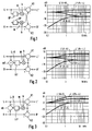
Die bekannten Modifikationsschaltungen von Fig. 1 bis Fig. 3 befinden sich beispielsweise in dem angegebenen Aufsatz in Elrad 1994, Heft 7, Seite 76 bis 81. Jede Schaltung weist dabei einen Eingang für ein Linkssignal L und einen anderen Eingang für ein Rechtssignal R auf. Entsprechend weist jede Modifikationsschaltung einen Ausgang für ein modifiziertes Linkssignal L' und einen anderen Ausgang ein modifiziertes Rechtssignal R' auf. Ferner enthält jede Schaltung eine erste und zweite Kombinationseinrichtung K1, K2, in der verschiedene Signalkomponenten miteinander kombiniert werden, in der Regel addiert oder subtrahiert, um schließlich das modifizierte Ausgangssignal L' bzw. R' zu bilden. Diese modifizierten Signale werden dann jeweils mindestens einem nicht dargestellten Lautsprecher zugeführt, wobei diese nicht zu dicht nebeneinander stehen dürfen. Es ist bekannt, daß nur dann ein Richtungseindruck erkennbar ist, wenn sich die beiden Signale L, R bzw. L', R' voneinander unterscheiden. Je größer der Unterschied ist, desto größer ist das Unterscheidungsvermögen, das schließlich dahingeht, daß die vom Hörer subjektiv georteten Schallquellen gleichsam auseinanderrücken. Durch die einzelnen Modifikationsschaltungen werden zur Vergrößerung der Stereo-Basis die Unterschiede in den einzelnen Signalen erhöht und der gemeinsame Signalanteil demgegenüber verkleinert. Der gemeinsame Signalanteil wird in der Regel als Monosignal und der Unterschied als Differenzsignal bezeichnet. Diese beiden Komponenten spielen bekanntlich bei der Übertragung des Stereo-Multiplexsignals eine wesentliche Rolle. Der Monoanteil für sich hört sich gut an. Der Differenzanteil ist jedoch keinem tatsächlichen Hörsignal zuzurechnen und hört sich alleine sehr unangenehm an.The known modification circuits from FIGS. 1 to 3 are found, for example, in the article cited in Elrad 1994, number 7, pages 76 to 81. Each circuit has an input for a left signal L and another input for a right signal R. Accordingly, each modification circuit has an output for a modified left signal L ' and another output has a modified right signal R ' . Furthermore, each circuit contains a first and second combination device K1, K2, in which different signal components are combined with one another, as a rule added or subtracted, in order finally to form the modified output signal L ' or R ' . These modified signals are then each fed to at least one loudspeaker (not shown), and these must not be too close together. It is known that a directional impression can only be recognized if the two signals L, R and L ' , R ' differ from one another. The greater the difference, the greater the ability to differentiate, which ultimately means that the sound sources subjectively located by the listener move apart, as it were. The individual modification circuits increase the differences in the individual signals to enlarge the stereo base and, on the other hand, reduce the common signal component. The common signal component is usually referred to as a mono signal and the difference as a difference signal. As is well known, these two components play an important role in the transmission of the stereo multiplex signal. The mono component in itself sounds good. However, the difference is not an actual audible signal and alone sounds very uncomfortable.
In sämtlichen Schaltungen von Fig. 1 bis Fig. 5 sind Filterschaltungen enthalten. Für Audiosignale ist jedoch davon auszugehen, daß in der Regel die niederen Frequenzanteile bis einige 100 Hz als Monosignal vorliegen und die Richtungsabhängigkeit nur die darüberliegenden Frequenzanteile betrifft. Hier trägt man der Tatsache Rechnung, daß tiefe Frequenzen vom menschlichen Ohr nicht nach Richtungen aufgelöst werden können. Die einzelnen Signalkomponenten, die das Rechts- und Linkssignal beeinflussen, sind somit hochpaßgefilterte Signale, so daß die in Vorwärtsrichtung arbeitenden Filterschaltungen durch Hochpässe HP realisiert sind. Der jeweilige Beitrag der einzelnen Signalkomponenten an der Modifikation wird durch Multiplizierer M und Gewichtungsfaktoren gesteuert, die negativ, positiv und dem Betrag nach größer als 1 sein können. In der Realität bewegen sich die Gewichtungsfaktoren in relativ engen Bereichen, weil sonst die erzeugten Effekte einen unechten Klangeindruck bewirken. In den Figuren 2 und 3 gibt es jeweils nur einen Multiplizierer M, der mittels eines zugeführten Signals k die Gewichtung bewirkt. In Fig. 1 befinden sich zwei Multiplizierer M, die beide mit dem Gewichtungsfaktor k angesteuert sind.Filter circuits are included in all of the circuits of FIGS. 1 to 5. For audio signals, however, it can be assumed that as a rule the lower ones Frequency components up to a few 100 Hz are available as mono signals and the directional dependence only affects the frequency components above. This takes into account the fact that low frequencies cannot be resolved by the human ear in any direction. The individual signal components that influence the right and left signal are thus high-pass filtered signals, so that the filter circuits operating in the forward direction are implemented by high-pass filters HP. The respective contribution of the individual signal components to the modification is controlled by multipliers M and weighting factors, which can be negative, positive and the amount greater than 1. In reality, the weighting factors move in relatively narrow areas, because otherwise the effects produced create a false sound impression. In FIGS. 2 and 3 there is only one multiplier M, which effects the weighting by means of a supplied signal k. In Fig. 1 there are two multipliers M, both of which are driven by the weighting factor k.
Die den einzelnen Schaltungen von Fig. 1 bis Fig. 3 zugrundeliegenden Überlegungen werden im folgenden beschrieben. Wie sich die Modifikationen dann auf die einzelnen modifizierten Signale auswirken, zeigen die jeweils nebenstehenden Frequenzdiagramme anhand folgender charakteristischer Signalinhalte:
- 1. Das ursprüngliche erste und zweite Signal L bzw. R sind einander entgegengesetzt gleich:

- 2. Das ursprüngliche erste und zweite Signal L bzw. R sind einander gleich:

- 3. Eines der ursprünglichen Signale L bzw. R hat den Wert Null: z.B. R = 0. Das bedeutet, daß das Summensignal (L + R) und das Differenzsignal (L - R) dem Betrag nach gleich sind. Das Summensignal (R + L) täuscht bei der Modifikation gegebenenfalls ein unspezifisches Signal (Monosignal) vor, das bei einer unzweckmäßigen Schaltung das Modifikationsergebnis stört. Mit diesen extrem einseitigen Signalen L und R = 0 läßt sich anschaulich darstellen, inwieweit Signalkomponenten bei der jeweiligen Modifikationsschaltung in den falschen Signalzweig eingekoppelt werden.
- 1. The original first and second signals L and R are mutually the same:
- 2. The original first and second signals L and R are the same:
- 3. One of the original signals L or R has the value zero: for example R = 0. This means that the sum signal (L + R) and the difference signal (L - R) are equal in amount. The sum signal (R + L) may fake an unspecific signal (mono signal) during the modification, which interferes with the result of the modification if the circuit is unsuitable. With these extremely one-sided signals L and R = 0, illustrate clearly to what extent signal components are coupled into the wrong signal branch in the respective modification circuit.
In jedem Fall wird angestrebt, daß der Frequenzgang nach der Modifikation möglichst gerade bleibt, weil sonst eine Klangverfälschung eintritt. Der Lautstärkeeindruck soll insgesamt auch nicht verändert werden.In any case, the aim is to keep the frequency response as straight as possible after the modification, because otherwise the sound will be distorted. The overall impression of volume should not be changed either.
In der bekannten Schaltungsanordnung von Fig. 1 wird der Richtungseindruck dadurch verstärkt, daß ein Teil des ersten und zweiten Signals L bzw. R, der durch den Gewichtungsfaktor k und jeweils ein Hochpaßfilter HP bestimmt wird, jeweils von dem anderen Signal R bzw. L abgezogen wird. Aus dem nebenstehenden Frequenzdiagramm ergibt sich, daß diese Modifikation dann ideal ist, wenn entweder nur ein erstes Signal L oder nur ein zweites Signal R vorliegt. Der zugehörige Frequenzgang L' mit R = 0 verläuft in diesem Fall eben. Signale, die einen höheren Summenanteil L + R (also R ist etwa gleich L) aufweisen, erscheinen bei höheren Frequenzen abgesenkt. Einander entgegengesetzte Signale ![]()
![]()
Das bekannte Schaltungsbeispiel von Fig. 2 verstärkt den Richtungseindruck, indem vom ersten und zweiten Signal L bzw. R Signalkomponenten mit gleichen Signalanteil, also Signale mit einem hohen Summenanteil L + R, abgezogen werden, wodurch die Unterschiede im ersten und zweiten Signal stärker hervortreten. Aus dem nebenstehenden Frequenzdiagramm ergibt sich, daß dies für ein Signalgemisch optimal ist, das einen wesentlichen Summenanteil R + L und zusätzlich eine hervorgehobene bzw. stark abgesenkte Signalquelle, z.B. R = 0, aufweist. Dies entspricht bei Audiosignalen einer einseitigen Schallquelle und einem hohen Monosignalanteil.The known circuit example of FIG. 2 reinforces the directional impression by subtracting signal components with the same signal component, that is to say signals with a high sum component L + R, from the first and second signals L and R, as a result of which the differences in the first and second signals become more apparent. The frequency diagram on the left shows that this is optimal for a signal mixture that has a significant sum of R + L and additionally a highlighted or greatly reduced signal source, e.g. R = 0. For audio signals, this corresponds to a one-sided sound source and a high proportion of mono signals.
In der bekannten Schaltungsanordnung von Fig. 3 wird schließlich aus dem ersten und zweiten Signal L bzw. R ein Differenzsignal L - R mittels eines Subtrahierers sb gebildet und daraus mittels eines Hochpasses HP und einer Gewichtungsstufe M eine Signalkomponente gebildet, die zum ersten Signal L hinzuaddiert und vom zweiten Signal R abgezogen wird. Durch die Addition und Subraktion des Differenzwertes wird der Unterschied des ersten und zweiten Signals vergrößert, so daß die modifizierten Signale L', R'am Ausgang einen verstärkten Richtungseffekt aufweisen und damit die Stereo-Basis vergrößern.In the known circuit arrangement of FIG. 3, a difference signal L-R is finally formed from the first and second signals L and R by means of a subtractor sb and a signal component is formed therefrom by means of a high-pass filter HP and a weighting stage M, which adds to the first signal L. and from the second Signal R is subtracted. The difference between the first and second signals is increased by adding and subtracting the difference value, so that the modified signals L ' , R ' have an amplified directional effect at the output and thus enlarge the stereo base.
Das nebenstehende Frequenzdiagramm zeigt, daß die Schaltung nach Fig. 3 für unspezifische Signale bzw. Monosignale mit ![]()
![]()
![]()
![]()
Die Erfindung lehrt, daß eine allgemeine Schaltung mit der alle Varianten realisiert werden können, durch die Einbeziehung weiterer Signalkomponenten bei der jeweiligen Modifikation zu bewerkstelligen ist, deren Einfluß durch zugehörige Gewichtungsfaktoren gesteuert wird. Die einzelnen Signalkomponenten werden ebenfalls mittels Kombinationseinrichtungen zusammengefaßt, d.h. addiert oder subtrahiert, um schließlich wieder ein modifiziertes erstes und zweites Signal L' bzw. R'zu erhalten.The invention teaches that a general circuit with which all variants can be realized can be accomplished by including further signal components in the respective modification, the influence of which is controlled by associated weighting factors. The individual signal components are also combined by means of combination devices, ie added or subtracted, in order finally to obtain a modified first and second signal L ' or R ' again.
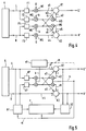
In Fig. 4 ist ein erstes Ausführungsbeispiel der Modifikationsschaltung nach der Erfindung dargestellt, bei der jedes modifizierte Signal durch drei Signalkomponenten gebildet wird. Um beliebige Modifikationen auszuführen, sollte jede Signalkomponente mittels einer Filterschaltung und eines Gewichtungsfaktors je nach Bedarf einzeln verändert werden können. Das Ausführungsbeispiel nach Fig.4 stellt insofern bereits eine Vereinfachung dar, weil jeweils zwei Signalkomponenten s2, s3 bzw. s5, s6 über einzige Filterschaltung F2 bzw. F4 geführt sind.4 shows a first exemplary embodiment of the modification circuit according to the invention, in which each modified signal is formed by three signal components. In order to carry out any modifications, it should be possible to change each signal component individually using a filter circuit and a weighting factor as required. The embodiment according to FIG. 4 already represents a simplification insofar as two signal components s2, s3 and s5, s6 are routed via a single filter circuit F2 and F4.
Eine Signalquelle q liefert an ihrem Ausgang ein erstes und ein zweites Signal L, R. Die Signalquelle q ist nicht näher bestimmt, sie kann beispielsweise auch eine Vielfachsignalquelle mit parallelen Ausgängen darstellen, wobei das erste und zweite Signal benachbarten Signalen zuzurechnen ist. Der besseren Übersicht wegen beschränken sich die Ausführungsbeispiele auf Stereo-Signale, wobei das erste Signal L einem Links-Signal und das zweite Signal R einem Rechts-Signal entspricht. Die Signalquelle q enthält in diesen Fällen einen Dekoder für Stereo-Multiplexsignale.A signal source q supplies a first and a second signal L, R at its output. The signal source q is not determined in more detail, it can also represent, for example, a multiple signal source with parallel outputs, the first and second signals being attributed to adjacent signals. For the sake of clarity, the exemplary embodiments are limited to stereo signals, the first signal L corresponding to a left signal and the second signal R corresponding to a right signal. In these cases, the signal source q contains a decoder for stereo multiplex signals.
In der Schaltung nach Fig. 4 ist das erste Signal L mittels eines ersten Filters F1 und einer ersten Gewichtungseinrichtung mit einem Multiplizierer M1 als erste Signalkomponente s1 auf einen Eingang einer ersten Kombinationseinrichtung K1 geführt. Der zugehörige Gewichtungsfaktor g ist dem ersten Multiplizierer M1 als Datenwert zugeführt oder entspricht einer festen Stellenverschiebung. Das erste Signal L ist ferner dem Eingang eines zweiten Filters F2 zugeführt und bildet mittels einer zweiten Gewichtungseinrichtung eine sechste Signalkomponente s6, die einer zweiten Kombinationseinrichtung K2 zugeführt ist, an deren Ausgang das zweite modifizierte Signal R' abgreifbar ist. Die Gewichtung in der zweiten Gewichtungseinrichtung bewirkt ein zweiter Multiplizierer M2, dessen Gewichtungseingang ein zweiter Gewichtungsfaktor k zugeführt ist. Nach der zweiten Gewichtungseinrichtung wird das Signal über eine dritte Gewichtungseinrichtung geführt und gelangt als zweite Signalkomponente s2 an die erste Kombinationseinrichtung K1. Die Gewichtung in der dritten Gewichtungseinrichtung bewirkt ein dritter Multiplizierer M3, dessen Gewichtungseingang ein dritter Gewichtungsfaktor α zugeführt ist. Parallel zu der ersten, zweiten und sechsten Signalkomponente s1, s2, s6 die aus dem ersten Signal L gebildet werden, werden aus dem zweiten Signal R eine vierte, fünfte und dritte Signalkomponente s4, s5, s3 gebildet. Dem ersten bzw. dem zweiten Filter F1, F2 entspricht ein drittes bzw. viertes Filter F3, F4. Dem ersten, zweiten und dritten Multiplizierer M1, M2, M3 entspricht ein vierter, fünfter und ein sechster Multiplizierer M4, M5, M6, denen der erste bzw. zweite bzw. dritte Gewichtungsfaktor g bzw. k bzw. α zugeführt ist. Die dritte bzw. sechste Signalkomponente s3, s6 sind auf einen Subtrahendeingang der ersten bzw. zweiten Kombinationseinrichtung K1, K2 geführt. Die Subtrahend-Eingänge lassen sich vermeiden, wenn die zugehörigen Gewichtungsfaktoren im Vorzeichen geändert werden.In the circuit according to FIG. 4, the first signal L is fed to an input of a first combination device K1 by means of a first filter F1 and a first weighting device with a multiplier M1 as the first signal component s1. The associated weighting factor g is supplied to the first multiplier M1 as a data value or corresponds to a fixed position shift. The first signal L is also fed to the input of a second filter F2 and forms, by means of a second weighting device, a sixth signal component s6 which is fed to a second combination device K2, at the output of which the second modified signal R 'can be tapped. The weighting in the second weighting device effects a second multiplier M2, the weighting input of which is supplied with a second weighting factor k. After the second weighting device, the signal is passed through a third weighting device and reaches the first combination device K1 as second signal component s2. The weighting in the third weighting device effects a third multiplier M3, the weighting input of which is supplied with a third weighting factor α. In parallel to the first, second and sixth signal components s1, s2, s6 which are formed from the first signal L, a fourth, fifth and third signal component s4, s5, s3 are formed from the second signal R. A third or fourth filter F3, F4 corresponds to the first or the second filter F1, F2. The first, second and third multipliers M1, M2, M3 correspond to a fourth, fifth and a sixth multiplier M4, M5, M6, to which the first, second and third weighting factors g, k and α are supplied. The third and sixth signal components s3, s6 are routed to a subtrahead input of the first and second combination devices K1, K2. The subtrahend inputs can be avoided if the associated weighting factors are changed in the sign.
In Fig. 5 ist ein anderes Ausführungsbeispiel der Erfindung dargestellt das die Schaltung von Fig. 4 in vereinfachter Form enthält. Daneben enthält die Schaltung Regeleinrichtungen, b1, b2, r und Steuereinrichtungen st zur Regelung und/oder Vorgabe der Gewichtungsfaktoren. Das Ausführungsbeispiel der Schaltung nach Fig. 5 ist noch stärker auf die Verarbeitung von Audiosignale ausgerichtet, als die allgemeinere Schaltung von Fig.4. Die Signalquelle q liefert als erstes und zweites Signal L, R ein Links- und Rechts-Signal. Die erste und vierte Signalkomponente s1, s4 sind dabei weder gefiltert noch gewichtet sondern entsprechen direkt dem ersten bzw. zweiten Signal L bzw. R. Mittels eines Hochpassfilters HP und der Gewichtung durch den zweiten Gewichtungsfaktor k wird aus dem ersten Signal L die sechste Signalkomponente s6 gebildet, die dem Subtrahendeingang der zweiten Kombinationseinrichtung K2 zugeführt ist. In gleicher Weise wird mittels eines Hochpassfilters HP und dem gleichen Gewichtungsfaktor k aus dem zweiten Signal R die dritte Signalkomponente s3 gebildet, die dem Subtrahendeingang der ersten Kombinationseinrichtung K1 zugeführt ist. Der zweite Gewichtungsfaktor k wird von der Steuereinrichtung st gesteuert, die somit die Höhe des gewünschten Effektes und damit die Stereobasisbreite beeinflußt. Da wie bereits angegeben die Richtungsabhängigkeit bei üblichen Stereosignalen nur im mittleren und oberen Frequenzbereich gegeben ist, werden zur Bildung der zweiten, dritten, fünften und sechsten Signalkomponente s2, s3, s5, s6 Hochpaßfilter HP verwendet, deren Grenzfrequenz großer als 300 Hz ist und typischerweise bei 700 Hz liegt. Aus den Frequenzdiagrammen von Fig. 1 bis Fig. 3 ist ersichtlich, daß über die Grenzfrequenz der Bereich der Signalanhebungen oder -absenkungen verändert wird, was sich bei gemischten Signalen auf den Höreindruck auswirkt. Aus dem hochpaßgefilterten ersten bzw. zweiten Signal wird die zweite bzw. fünfte Signalkomponente s2, s5 gebildet, indem das Signal mittels des dritten Gewichtungsfaktors α in seiner Größe geändert wird. Über den Wert des dritten Gewichtungsfaktors α lassen sich nun nicht nur die Eigenschaften der bekannten Schaltungen von Fig. 1 bis Fig. 3 einstellen, sondern auch noch beliebige Zwischenstufen, wodurch eine optimale Signalanpassung ermöglicht wird.FIG. 5 shows another exemplary embodiment of the invention which contains the circuit of FIG. 4 in a simplified form. In addition, the circuit contains regulating devices, b1, b2, r and control devices st for regulating and / or specifying the weighting factors. The embodiment of the circuit according to FIG. 5 is oriented even more towards the processing of audio signals than the more general circuit from FIG. 4. The signal source q provides the first and second signals L, R a left and right signal. The first and fourth signal components s1, s4 are neither filtered nor weighted but correspond directly to the first and second signals L and R. By means of a high-pass filter HP and the weighting by the second weighting factor k, the first signal L is used to form the sixth signal component s6, which is fed to the subtrahend input of the second combination device K2 . In the same way, the third signal component s3, which is fed to the subtrahend input of the first combination device K1, is formed from the second signal R by means of a high-pass filter HP and the same weighting factor k. The second weighting factor k is controlled by the control device st, which thus influences the level of the desired effect and thus the stereo base width. Since, as already stated, the directionality is only given in the middle and upper frequency range for conventional stereo signals, high-pass filters HP, whose cut-off frequency is greater than 300 Hz and typically, are used to form the second, third, fifth and sixth signal components s2, s3, s5, s6 is at 700 Hz. It can be seen from the frequency diagrams of FIGS. 1 to 3 that the range of the signal increases or decreases is changed via the cut-off frequency, which has an effect on the auditory impression in the case of mixed signals. The second and fifth signal components s2, s5 are formed from the high-pass filtered first and second signals, respectively, by changing the size of the signal by means of the third weighting factor α. The value of the third weighting factor α can now be used to set not only the properties of the known circuits from FIGS. 1 to 3, but also any intermediate stages, which enables optimum signal adaptation.
Mit einem Gewichtungsfaktor α = 0 wird das Frequenzdiagrammm von Fig. 1 eingestellt, das eine optimale Modifikation für Stereosignale liefert, bei der eine der beiden Komponenten L, R den Wert 0 hat. Mit einem Gewichtungsfaktor α, der etwa zwischen 0,4 und 0,5 liegt, wird ein Frequenzgang eingestellt, der dem Frequenzgang von Fig. 2 entspricht und für gemischte Signale optimal ist. Gegebenenfalls kann der dritte Gewichtungsfaktor α auch negativ sein, um die Signalanhebung für unspezifische Signale im oberen Frequenzbereich zu reduzieren. Schließlich wird mit einem Gewichtungsfaktor α = 1 der Frequenzgang von Fig. 3 eingestellt, der für reine Monosignale oder Signale mit hohem Monosignalanteil ideal ist.The frequency diagram m of FIG. 1 is set with a weighting factor α = 0, which provides an optimal modification for stereo signals in which one of the two components L, R has the
Die Einstellung des dritten Gewichtungsfaktors α kann auf verschiedene Weise erfolgen. Entweder als Festwert über die Steuereinrichtung st - in Fig. 5 ist dies durch eine gestrichelte Verbindung dargestellt. Der dritte Gewichtungsfaktor α kann aber auch adaptiv durch die Signaleigenschaften selbst gesteuert werden, die beispielsweise mittels einer ersten Bewertungseinrichtung b1 aus dem Links- und Rechtssignal L, R bestimmt werden. Im einfachsten Fall wird hierbei über Addierer bzw. Subtrahierer der Mono- bzw. Differenzsignalanteil bestimmt. Mittels einzelner Filter, mit denen die physiologische Hörempfindlichkeit etwa nachgebildet wird, können einzelne Frequenzbereiche gesondert behandelt oder speziell gewichtet werden. Dies entspricht einer adaptiven Steuerung des Gewichtungsfaktors α, die in Fig. 5 durch die gestrichelte Linie am Ausgang der ersten Bewertungseinrichtung b1 schematisch dargestellt ist.The third weighting factor α can be set in different ways. Either as a fixed value via the control device st - this is shown in FIG. 5 by a dashed connection. However, the third weighting factor α can also be controlled adaptively by the signal properties themselves, which are determined, for example, by means of a first evaluation device b1 from the left and right signals L, R. In the simplest case, the mono or difference signal component is determined via adders or subtractors. Individual frequency ranges can be treated separately or specially weighted by means of individual filters with which the physiological hearing sensitivity is simulated, for example. This corresponds to an adaptive control of the weighting factor α, which is shown schematically in FIG. 5 by the dashed line at the output of the first evaluation device b1.
Wird eine entsprechende Bewertung mittels einer zweiten Bewertungseinrichtung b2 auch an den modifizierten Ausgangssignalen L', R' durchgeführt, dann können die Ausgänge der ersten und zweiten Bewertungseinrichtung b1, b2 mit einer Regeleinrichtung r verbunden werden, deren Ausgang die Höhe der Gewichtungsfaktoren steuert. Durch einen Vergleich der Ein- und Ausgangssignale der Modifikationsschaltung kann mittels der Regeleinrichtung r insbesondere erreicht werden, daß sich unabhängig von der jeweiligen Effektsteuerung der Lautstärkeeindruck bei der Modifikation nicht ändert. Wenn die Regeleinrichtung r den Lautstärkeeindruck im gesamten Frequenzbereich oder in einzelnen Frequenzbereichen berücksichtigen soll, dann müssen die erste und zweite Bewertungseinrichtung b1, b2 unter anderem leistungsbezogene Daten aus den Signalen am Eingang und Ausgang der Modifikationsschaltung bestimmen. Im Ausführungsbeispiel von Fig. 5 steuert der Ausgang der Regeleinrichtung r den dritten Gewichtungsfaktor α.If a corresponding evaluation is also carried out on the modified output signals L ' , R ' by means of a second evaluation device b2, the outputs of the first and second evaluation devices b1, b2 can be connected to a control device r, the output of which controls the level of the weighting factors. By comparing the input and output signals of the modification circuit, the control device r can be used, in particular, to ensure that the volume impression does not change during the modification, regardless of the respective effect control. If the control device r is to take into account the volume impression in the entire frequency range or in individual frequency ranges, then the first and second evaluation devices b1, b2 must determine, among other things, performance-related data from the signals at the input and output of the modification circuit. In the exemplary embodiment of FIG. 5, the output of the control device r controls the third weighting factor α.
Selbstverständlich ist auch eine Kombination der Bewertungs- und Regeleinrichtungen von Fig. 5 mit der Modifikationsschaltung von Fig. 4 denkbar. Hier kann über den ersten Gewichtungsfaktor g der Anteil des ersten bzw. zweiten Signales L, R gesteuert werden. Das erste und dritte Filter F1, F3 können dabei durchverbunden oder jeweils durch einen Allpass realisiert sein. Die bei digitalen Schaltungen erforderlichen Zeitausgleiche sind wie üblich in den einzelnen Schaltungsbeispielen nicht dargestellt. Es wird nochmals darauf hingewiesen, daß die Erfindung und die zugehörigen Ausführungsbeispiele keinesfalls auf die Verarbeitung von Stereo-Signalen beschränkt sind, sondern daß die adaptive Effektsteuerung für viele andere Signale von Vorteil ist.Of course, a combination of the evaluation and control devices from FIG. 5 with the modification circuit from FIG. 4 is also conceivable. Here, the proportion of the first or second signal L, R can be controlled via the first weighting factor g. The first and third filters F1, F3 can be connected through or can be implemented by an all-pass. The time equalizations required for digital circuits are, as usual, not shown in the individual circuit examples. It is again pointed out that the invention and the associated exemplary embodiments are in no way limited to the processing of stereo signals, but that the adaptive effect control is advantageous for many other signals.
Claims (10)
gekennzeichnet durch folgende Merkmale:
characterized by the following features:
Priority Applications (5)
| Application Number | Priority Date | Filing Date | Title |
|---|---|---|---|
| DE59509187T DE59509187D1 (en) | 1995-11-25 | 1995-11-25 | Signal modification circuit |
| EP95118595A EP0776144B1 (en) | 1995-11-25 | 1995-11-25 | Signal modification circuit |
| US08/754,144 US5822437A (en) | 1995-11-25 | 1996-11-22 | Signal modification circuit |
| JP8311836A JPH09191499A (en) | 1995-11-25 | 1996-11-22 | Signal correction circuit |
| KR1019960056382A KR100424520B1 (en) | 1995-11-25 | 1996-11-22 | Signal modification circuit and method |
Applications Claiming Priority (1)
| Application Number | Priority Date | Filing Date | Title |
|---|---|---|---|
| EP95118595A EP0776144B1 (en) | 1995-11-25 | 1995-11-25 | Signal modification circuit |
Publications (2)
| Publication Number | Publication Date |
|---|---|
| EP0776144A1 true EP0776144A1 (en) | 1997-05-28 |
| EP0776144B1 EP0776144B1 (en) | 2001-04-11 |
Family
ID=8219836
Family Applications (1)
| Application Number | Title | Priority Date | Filing Date |
|---|---|---|---|
| EP95118595A Expired - Lifetime EP0776144B1 (en) | 1995-11-25 | 1995-11-25 | Signal modification circuit |
Country Status (5)
| Country | Link |
|---|---|
| US (1) | US5822437A (en) |
| EP (1) | EP0776144B1 (en) |
| JP (1) | JPH09191499A (en) |
| KR (1) | KR100424520B1 (en) |
| DE (1) | DE59509187D1 (en) |
Families Citing this family (10)
| Publication number | Priority date | Publication date | Assignee | Title |
|---|---|---|---|---|
| FI106355B (en) * | 1998-05-07 | 2001-01-15 | Nokia Display Products Oy | A method and apparatus for synthesizing a virtual audio source |
| US7136493B2 (en) * | 2000-06-28 | 2006-11-14 | Peavey Electronics Corporation | Sub-harmonic generator and stereo expansion processor |
| US7242779B2 (en) * | 2002-05-30 | 2007-07-10 | Peavey Electronics Corporation | Methods and apparatus for sub-harmonic generation, stereo expansion and distortion |
| JP4509686B2 (en) * | 2004-07-29 | 2010-07-21 | 新日本無線株式会社 | Acoustic signal processing method and apparatus |
| JP2009065436A (en) * | 2007-09-06 | 2009-03-26 | New Japan Radio Co Ltd | Stereo reproducing apparatus |
| US8335331B2 (en) * | 2008-01-18 | 2012-12-18 | Microsoft Corporation | Multichannel sound rendering via virtualization in a stereo loudspeaker system |
| US8577065B2 (en) * | 2009-06-12 | 2013-11-05 | Conexant Systems, Inc. | Systems and methods for creating immersion surround sound and virtual speakers effects |
| US20150036826A1 (en) * | 2013-05-08 | 2015-02-05 | Max Sound Corporation | Stereo expander method |
| US20150036828A1 (en) * | 2013-05-08 | 2015-02-05 | Max Sound Corporation | Internet audio software method |
| US20140362996A1 (en) * | 2013-05-08 | 2014-12-11 | Max Sound Corporation | Stereo soundfield expander |
Citations (7)
| Publication number | Priority date | Publication date | Assignee | Title |
|---|---|---|---|---|
| GB2180727A (en) * | 1985-09-12 | 1987-04-01 | Sgs Microelettronica Spa | Non-recursive system for expanding the stereo base of stereophonic acoustic diffusion apparatus |
| WO1990000851A1 (en) * | 1988-07-08 | 1990-01-25 | Adaptive Control Limited | Improvements in or relating to sound reproduction systems |
| EP0476790A2 (en) * | 1986-03-27 | 1992-03-25 | SRS LABS, Inc. | Stereo enhancement system |
| US5136650A (en) * | 1991-01-09 | 1992-08-04 | Lexicon, Inc. | Sound reproduction |
| EP0615399A1 (en) * | 1993-03-09 | 1994-09-14 | Matsushita Electric Industrial Co., Ltd. | Sound field controller |
| EP0637191A2 (en) * | 1993-07-30 | 1995-02-01 | Victor Company Of Japan, Ltd. | Surround signal processing apparatus |
| US5420929A (en) * | 1992-05-26 | 1995-05-30 | Ford Motor Company | Signal processor for sound image enhancement |
Family Cites Families (14)
| Publication number | Priority date | Publication date | Assignee | Title |
|---|---|---|---|---|
| KR880005354A (en) * | 1986-10-08 | 1988-06-28 | 나까무라 겐조 | Electronic actuator |
| JPH0435499A (en) * | 1990-05-31 | 1992-02-06 | Sony Corp | Sound attaching circuit |
| DE4028447A1 (en) * | 1990-09-07 | 1992-03-12 | Teves Gmbh Alfred | ELECTROMAGNETIC VALVE FOR HYDRAULIC BRAKE SYSTEMS WITH SLIP CONTROL |
| DE4030424A1 (en) * | 1990-09-26 | 1992-04-02 | Bosch Gmbh Robert | PRESSURE LIMIT VALVE, IN PARTICULAR FOR HYDRAULIC VEHICLE BRAKE SYSTEMS |
| DE4030971A1 (en) * | 1990-10-01 | 1992-04-02 | Bosch Gmbh Robert | Electromagnet-actuated valve esp. for vehicular hydraulic braking - has fluid passages through sleeve in which transverse wall is arranged to provide seating for plunger |
| DE4103365A1 (en) * | 1991-02-05 | 1992-08-13 | Teves Metallwaren Alfred | PRESSURE CONTROL VALVE |
| DE9102383U1 (en) * | 1991-02-28 | 1991-05-16 | Tuerk & Hillinger Gmbh, 7200 Tuttlingen, De | |
| DE9107436U1 (en) * | 1991-06-17 | 1991-08-22 | Binder Magnete Gmbh, 7730 Villingen-Schwenningen, De | |
| DE4129638C2 (en) * | 1991-09-06 | 2002-01-10 | Bosch Gmbh Robert | Hydraulic seat valve |
| DE4135062A1 (en) * | 1991-10-24 | 1993-04-29 | Bosch Gmbh Robert | METHOD FOR ACCELERATING BRAKE INTERVENTION IN DRIVE-SLIP REGULATION AND HYDRAULIC BRAKE SYSTEM FOR CARRYING OUT THE METHOD |
| DE4141546C2 (en) * | 1991-12-17 | 2002-02-14 | Continental Teves Ag & Co Ohg | Solenoid valve, especially for hydraulic brake systems with slip control |
| DE4236047A1 (en) * | 1992-10-24 | 1994-04-28 | Teves Gmbh Alfred | Brake system with anti-lock and / or traction control |
| EP0691050B1 (en) * | 1993-03-24 | 1996-12-18 | Blaupunkt-Werke GmbH | Circuit for deriving audio signal masking signals |
| US5440638A (en) * | 1993-09-03 | 1995-08-08 | Q Sound Ltd. | Stereo enhancement system |
-
1995
- 1995-11-25 EP EP95118595A patent/EP0776144B1/en not_active Expired - Lifetime
- 1995-11-25 DE DE59509187T patent/DE59509187D1/en not_active Expired - Fee Related
-
1996
- 1996-11-22 KR KR1019960056382A patent/KR100424520B1/en not_active IP Right Cessation
- 1996-11-22 JP JP8311836A patent/JPH09191499A/en active Pending
- 1996-11-22 US US08/754,144 patent/US5822437A/en not_active Expired - Lifetime
Patent Citations (7)
| Publication number | Priority date | Publication date | Assignee | Title |
|---|---|---|---|---|
| GB2180727A (en) * | 1985-09-12 | 1987-04-01 | Sgs Microelettronica Spa | Non-recursive system for expanding the stereo base of stereophonic acoustic diffusion apparatus |
| EP0476790A2 (en) * | 1986-03-27 | 1992-03-25 | SRS LABS, Inc. | Stereo enhancement system |
| WO1990000851A1 (en) * | 1988-07-08 | 1990-01-25 | Adaptive Control Limited | Improvements in or relating to sound reproduction systems |
| US5136650A (en) * | 1991-01-09 | 1992-08-04 | Lexicon, Inc. | Sound reproduction |
| US5420929A (en) * | 1992-05-26 | 1995-05-30 | Ford Motor Company | Signal processor for sound image enhancement |
| EP0615399A1 (en) * | 1993-03-09 | 1994-09-14 | Matsushita Electric Industrial Co., Ltd. | Sound field controller |
| EP0637191A2 (en) * | 1993-07-30 | 1995-02-01 | Victor Company Of Japan, Ltd. | Surround signal processing apparatus |
Also Published As
| Publication number | Publication date |
|---|---|
| US5822437A (en) | 1998-10-13 |
| KR970032266A (en) | 1997-06-26 |
| EP0776144B1 (en) | 2001-04-11 |
| KR100424520B1 (en) | 2004-06-18 |
| JPH09191499A (en) | 1997-07-22 |
| DE59509187D1 (en) | 2001-05-17 |
Similar Documents
| Publication | Publication Date | Title |
|---|---|---|
| DE2616762C2 (en) | Device for expanding a stereophonic sound image | |
| DE69433258T2 (en) | Surround sound signal processing device | |
| DE19715498B4 (en) | Stereo sound image enhancement apparatus and methods using tables | |
| EP1912471B1 (en) | Processing of an input signal in a hearing aid | |
| DE2720984B2 (en) | ||
| DE3519644A1 (en) | METHOD AND DEVICE FOR PLAYING SOUND WITH A REALISTIC SPACE SOUND IMPRESSION | |
| DE4136022A1 (en) | Stereo acoustic field expansion and asymmetry correction appts. - applies phase and level corrections to digitised channel signals for crosstalk adjustment with buffering and delay | |
| DE69533211T2 (en) | Signal combination circuit for stereophonic reproduction with cross signal coupling | |
| DE2627437C3 (en) | Quadrophony system for head-related four-channel stereophony with loudspeaker reproduction | |
| EP2939445B1 (en) | Production of 3d audio signals | |
| DE112012006457B4 (en) | Frequency characteristic modification device | |
| DE2512287A1 (en) | SOUND PLAYBACK SYSTEM | |
| DE3040896C2 (en) | Circuit arrangement for generating and processing stereophonic signals from a monophonic signal | |
| EP0825800A2 (en) | Method and apparatus for generating multi-audio signals from a mono audio signal | |
| EP0808076B1 (en) | Surround sound system | |
| DE3806915C2 (en) | ||
| EP0776144B1 (en) | Signal modification circuit | |
| WO2015049334A1 (en) | Method and apparatus for downmixing a multichannel signal and for upmixing a downmix signal | |
| DE3626815C2 (en) | Circuit for broadening the stereo base for stereophonic sound reproduction devices | |
| DE10334396B3 (en) | Electrical hearing aid has individual microphones combined to provide 2 microphone units in turn combined to provide further microphone unit with same order directional characteristic | |
| DE3142157C2 (en) | ||
| EP1104221B1 (en) | Sounding device | |
| DE19900961A1 (en) | Method and device for reproducing multi-channel sound signals | |
| DE2129673C3 (en) | Multidirectional sound systems, decoders and encoders therefor | |
| DE19628261A1 (en) | Method and device for electronically embedding directional inserts in two-channel sound |
Legal Events
| Date | Code | Title | Description |
|---|---|---|---|
| PUAI | Public reference made under article 153(3) epc to a published international application that has entered the european phase |
Free format text: ORIGINAL CODE: 0009012 |
|
| AK | Designated contracting states |
Kind code of ref document: A1 Designated state(s): DE FR GB IT NL |
|
| 17P | Request for examination filed |
Effective date: 19971128 |
|
| RAP1 | Party data changed (applicant data changed or rights of an application transferred) |
Owner name: MICRONAS INTERMETALL GMBH |
|
| 17Q | First examination report despatched |
Effective date: 19990323 |
|
| RAP1 | Party data changed (applicant data changed or rights of an application transferred) |
Owner name: MICRONAS GMBH |
|
| GRAG | Despatch of communication of intention to grant |
Free format text: ORIGINAL CODE: EPIDOS AGRA |
|
| GRAG | Despatch of communication of intention to grant |
Free format text: ORIGINAL CODE: EPIDOS AGRA |
|
| GRAH | Despatch of communication of intention to grant a patent |
Free format text: ORIGINAL CODE: EPIDOS IGRA |
|
| GRAH | Despatch of communication of intention to grant a patent |
Free format text: ORIGINAL CODE: EPIDOS IGRA |
|
| GRAA | (expected) grant |
Free format text: ORIGINAL CODE: 0009210 |
|
| AK | Designated contracting states |
Kind code of ref document: B1 Designated state(s): DE FR GB IT NL |
|
| GBT | Gb: translation of ep patent filed (gb section 77(6)(a)/1977) |
Effective date: 20010425 |
|
| REF | Corresponds to: |
Ref document number: 59509187 Country of ref document: DE Date of ref document: 20010517 |
|
| ITF | It: translation for a ep patent filed |
Owner name: BUGNION S.P.A. |
|
| ET | Fr: translation filed | ||
| REG | Reference to a national code |
Ref country code: GB Ref legal event code: IF02 |
|
| PLBE | No opposition filed within time limit |
Free format text: ORIGINAL CODE: 0009261 |
|
| STAA | Information on the status of an ep patent application or granted ep patent |
Free format text: STATUS: NO OPPOSITION FILED WITHIN TIME LIMIT |
|
| 26N | No opposition filed | ||
| PGFP | Annual fee paid to national office [announced via postgrant information from national office to epo] |
Ref country code: NL Payment date: 20071124 Year of fee payment: 13 |
|
| PGFP | Annual fee paid to national office [announced via postgrant information from national office to epo] |
Ref country code: IT Payment date: 20071128 Year of fee payment: 13 |
|
| PGFP | Annual fee paid to national office [announced via postgrant information from national office to epo] |
Ref country code: GB Payment date: 20071128 Year of fee payment: 13 Ref country code: FR Payment date: 20071119 Year of fee payment: 13 |
|
| PGFP | Annual fee paid to national office [announced via postgrant information from national office to epo] |
Ref country code: DE Payment date: 20071221 Year of fee payment: 13 |
|
| GBPC | Gb: european patent ceased through non-payment of renewal fee |
Effective date: 20081125 |
|
| PG25 | Lapsed in a contracting state [announced via postgrant information from national office to epo] |
Ref country code: NL Free format text: LAPSE BECAUSE OF NON-PAYMENT OF DUE FEES Effective date: 20090601 |
|
| NLV4 | Nl: lapsed or anulled due to non-payment of the annual fee |
Effective date: 20090601 |
|
| PG25 | Lapsed in a contracting state [announced via postgrant information from national office to epo] |
Ref country code: IT Free format text: LAPSE BECAUSE OF NON-PAYMENT OF DUE FEES Effective date: 20081125 |
|
| REG | Reference to a national code |
Ref country code: FR Ref legal event code: ST Effective date: 20090731 |
|
| PG25 | Lapsed in a contracting state [announced via postgrant information from national office to epo] |
Ref country code: DE Free format text: LAPSE BECAUSE OF NON-PAYMENT OF DUE FEES Effective date: 20090603 |
|
| PG25 | Lapsed in a contracting state [announced via postgrant information from national office to epo] |
Ref country code: GB Free format text: LAPSE BECAUSE OF NON-PAYMENT OF DUE FEES Effective date: 20081125 |
|
| PG25 | Lapsed in a contracting state [announced via postgrant information from national office to epo] |
Ref country code: FR Free format text: LAPSE BECAUSE OF NON-PAYMENT OF DUE FEES Effective date: 20081130 |