EP0777396A1 - Maintaining the composition of transferred data during handover - Google Patents
Maintaining the composition of transferred data during handover Download PDFInfo
- Publication number
- EP0777396A1 EP0777396A1 EP96660078A EP96660078A EP0777396A1 EP 0777396 A1 EP0777396 A1 EP 0777396A1 EP 96660078 A EP96660078 A EP 96660078A EP 96660078 A EP96660078 A EP 96660078A EP 0777396 A1 EP0777396 A1 EP 0777396A1
- Authority
- EP
- European Patent Office
- Prior art keywords
- cells
- base station
- mobile unit
- data
- message
- Prior art date
- Legal status (The legal status is an assumption and is not a legal conclusion. Google has not performed a legal analysis and makes no representation as to the accuracy of the status listed.)
- Withdrawn
Links
Images


Classifications
-
- H—ELECTRICITY
- H04—ELECTRIC COMMUNICATION TECHNIQUE
- H04W—WIRELESS COMMUNICATION NETWORKS
- H04W36/00—Hand-off or reselection arrangements
- H04W36/02—Buffering or recovering information during reselection ; Modification of the traffic flow during hand-off
-
- H—ELECTRICITY
- H04—ELECTRIC COMMUNICATION TECHNIQUE
- H04L—TRANSMISSION OF DIGITAL INFORMATION, e.g. TELEGRAPHIC COMMUNICATION
- H04L1/00—Arrangements for detecting or preventing errors in the information received
- H04L1/12—Arrangements for detecting or preventing errors in the information received by using return channel
- H04L1/16—Arrangements for detecting or preventing errors in the information received by using return channel in which the return channel carries supervisory signals, e.g. repetition request signals
- H04L1/18—Automatic repetition systems, e.g. Van Duuren systems
- H04L1/1829—Arrangements specially adapted for the receiver end
-
- H—ELECTRICITY
- H04—ELECTRIC COMMUNICATION TECHNIQUE
- H04W—WIRELESS COMMUNICATION NETWORKS
- H04W92/00—Interfaces specially adapted for wireless communication networks
- H04W92/16—Interfaces between hierarchically similar devices
- H04W92/20—Interfaces between hierarchically similar devices between access points
Definitions
- the invention generally relates to procedures aimed at maintaining the reliability of data transmission in wireless telecommunications systems comprising several base stations, and in particular to maintaining the composition of the data carried in data cells during a handover in a system which transfers data as data cells whose relative order is significant.
- the ATM (Asynchronous Transfer Mode) is a strong candidate for a fast future transfer protocol in B-ISDN networks (Broadband Integrated Services Digital Network), for example, and generally in communications between data transmission devices.
- the network consists of nodes and terminals, and of links between them.
- data is transferred as cells in digital form, each cell comprising a so-called payload of 48 bytes and a header of 5 bytes.
- the headers do not contain complete routing information between the transmitting and the receiving devices but only information on the virtual path and channel in which the respective data transfer connection is carried.
- the nodes of the network contain the necessary routing information on the basis of which the respective identifiers of the virtual path and channel are interpreted as a reference for the next respective node.
- the relative order of the cells must remain the same throughout the transmission because there is no specific mechanism in the ATM network that can be used to rearrange out-of-order cells.
- a typical cellular network comprises several base stations (BS) which are affiliated with - possibly through a base station controller (BSC) - a mobile switching center (MSC).
- BSC base station controller
- MSC mobile switching center
- cell is in this patent application used to refer only to the transferred data unit defined by a given data transmission system, the length of the unit being the above-mentioned 53 bytes in the ATM system which is used as an example.
- a typical phenomenon of cellular systems is the change of base stations, i.e., the handover, where a given mobile terminal moves from the transmission range of a first base station to that of a second base station, whereby essentially all the data transmission between the terminal in question and the network is rerouted through the new base station.
- a perfect synchronization of the operation during the handover is often not possible, which may result in packet loss, duplication or misordering. This is especially severe in the ATM system where a successful transmission of all the cells and ordering are a prerequisite for effective data transmission.
- a handover may take place without a notice or with a notice.
- the former refers to a situation where the connection between the base station and the terminal breaks quickly and the latter implies that, where the connection worsens gradually, one can prepare for procedures required for handover.
- the doctoral thesis of S. K. Biswas "Handling Realtime Traffic in Mobile Networks" discloses procedures for implementing a handover both without a notice and with a notice.
- the handover of base stations is described briefly in the following with reference to Figs. 1 and 2.
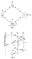
- Fig. 1 presents the mobile unit MU, two base stations BSp and BSq, and mobile representative MR which is in charge of routing the traffic between the said base stations and the rest of the data transmission network.
- the data transfer segments between the said devices are designated letters i, j, k, and 1.
- the data transfer segment directed from mobile representative MR to the rest of the network is designated s.
- the data directed from mobile unit MU to the network is called uplink data and the data propagating in the opposite direction is called downlink data.
- Fig. 2 presents signals between the said devices by means of numbered arrows, relating to the handover with a notice in which BSp is the old base station and BSq is the new base station.
- Mobile unit MU stops transmitting uplink cells along segment i and transmits initiate message 21 to new base station BSq.
- BSq transmits forward message 22 to mobile representative MR on the need to reroute.
- mobile representative MR stops sending downlink data, which arrives along segment s, to old base station BSp along segment k, and directs it to new base station BSq through segment 1.
- mobile representative MR Before transmitting the actual data to be transmitted, mobile representative MR transmits reply message 23 which is forwarded to the mobile unit as ack message 24 by base station BSq.
- the new base station creates a temporary FIFO buffer (first in, first out) 25 for storing the downlink data that comes from mobile representative MR. It is not until mobile unit MU believes it has received all the downlink data which had been directed from mobile representative MR via segment k to old base station BSp before switching the connection to segment 1, that it transmits done message 26 to new base station BSq and starts to transmit uplink data. As a response to done 26, new base station BSq starts sending downlink data (by first unloading buffer 25) and, for its part, finishes the handover by sending complete message 27 to mobile representative MR.
- FIFO buffer first in, first out
- Fig. 2 presents the interrupt time of the uplink data, represented by a shaded bar, the interrupt time of the downlink data in mobile representative MR, represented by a black bar, and the interrupt time of the downlink data in new base station BSq, represented by a white bar.
- the handover without a notice comprises several similar procedures, but disruptions in data transmission can be longer because delay is caused in the time spent before a break is detected in the connection passing through the old base station.
- the one with a notice and the one without a notice it is possible that there is packet loss or packet misordering.
- mobile representative MR breaks off the data transmission from segment k to the network before all the uplink cells have been transmitted across segments i and k. After the connection is terminated, the cells in question are considered lost, or if they are still directed to the network, they can be out of order in the uplink.
- the downlink cells which have been directed to segments k and i before the handover, may be lost altogether because of a weak radio link, or they can arrive late in mobile unit MU, causing out-of-ordering in the downlink.
- Packet loss and out-of-ordering usually results in that an erroneous checksum or other indicator is detected on a higher protocol level, whereby a given protocol data unit (PDA) comprising several cells is denied and requested to be sent again. This is uneconomic from the point of view of the network resource utilization.
- PDA protocol data unit
- Patent publication EP 426 269 to British Telecommunications discloses a method in which the base stations are assembled in groups of several base stations. To facilitate and speed up the handover, all the cells directed to a mobile unit in the transmission range of a given base station are sent to all the base stations of the same group by means of the data transmission network.
- the publication presents an idea according to which the old base station sends all the cells delivered to it, and after this, the new base station starts sending the cells delivered through it.
- the publication also presents a predictor which is incorporated in the base station controller or in the mobile representative that controls the base stations. The task of the predictor is to monitor the movement of the mobile unit from one transmission range to another and to estimate as to where the mobile unit will migrate next.
- Patent publication EP 366 342 to AT&T discloses a method in which data is transmitted as cells in a cellular radio network and the header segment of each cell comprises an unchanging segment which remains unmodified regardless of the changes in routing, and a changing segment whose contents vary during a handover or during other rerouting processes.
- the publication suggests that the arrangement can be used to facilitate the handover, but only the definition of the routing is benefited.
- a similar method is disclosed in patent publication EP 577 959 to Roke Manor Research Ltd., relating to the ATM network in particular.
- the unchanging segment in the cell header is a so-called VCI field (Virtual Channel Identifier) and the changing segment is a so-called VPI field (Virtual Path Identifier).
- VCI field Virtual Channel Identifier
- VPI field Virtual Path Identifier
- Patent publication EP 577 960 to Roke Manor Research Ltd. discloses a method in which at least one of the base stations of a cellular network is affiliated, through the ATM network, with at least two mobile representatives which, in the disclosed arrangement, also function as repeaters between the ATM network and a fixed telephone network.
- the idea is to arrange the VPIs and the VCIs of the ATM network which control the routing so that even though a given mobile unit moves into the transmission range of another mobile representative (or mobile services switching center), the routing is implemented by linking via the original mobile representative.
- the arrangement has some advantages in decreasing the amount of switchings in the network but it does not have an effect on packet loss between the base stations and the mobile unit and/or on the delay of cells during a handover.
- the purpose is to contribute to the synchronization and combination of steams of cells that arrive at a given conjuction point along two parallel routes.
- the purpose in numbering the cells is aimed particularly at identifying them unequivocally, so that cells are not duplicated or lost when the streams of cells are combined and their order will remain the same. In this case, a problem might occur because only numbers from 0 to 15 can be presented in the GFC field which has a maximum of four bits, whereby the numbering cycle remains so short that cells with the same number belonging to subsequent cycles may become out-of-ordered.
- the objects of the invention are accomplished by a method which can be used to refer to the cells of the system with an accuracy of at least a given number of cells, so that the base stations can exchange information on which cells have been sent and/or received successfully during the handover.
- the method according to the invention for performing handover processes in a system that applies cellular data transmission and comprises a switch, a first and a second base station and a mobile unit is characterized in that the first base station provides the switch and/or the second base station with information on which cells have been successfully transmitted between the first base station and the mobile unit, so that the transmission of cells continues between the second base station and the mobile unit, beginning with the first cell that has not been successfully transmitted between the first base station and the mobile unit.
- the invention is further related to the base station of a wireless data transmission system.
- the base station according to the invention is characterized in comprising a means for dispatching information to other base stations on which cells have been transmitted successfully and in the right order between the base station and the mobile unit, and a means for receiving the corresponding information from the other base stations.
- the invention is further related to a data transmission system.
- the data transmission system according to the invention is characterized in comprising a means for transmitting messages between the base station on the cells of the transferred cellular data.
- the invention is based on the insight according to which the base stations may well exchange data on the success of the transmission and/or the reception of cells, even though the specifications of the data transmission system do not support the reference to discrete cells per se.
- synchronization mechanisms can be provided in a manner described below, by means of which the old and the new base stations participating in the handover share information on which cells have been successfully transmitted to the mobile unit and/or received from there.
- the point in the stream of cells from where the transmission is to be continued can be indicated to the new base station.
- the cells that were not transmitted and/or received via the old base station can be designated to be sent and/or received through the new base station.
- the ATM system is dealt with as an exemplary object of application of the invention, the system being characterized in a high data transfer rate, the relatively small size of cells, and the small number of available cell header fields which is due to stringent specifications.
- the invention can also be applied in other data transmission methods and systems whose specifications do not support the reference to discrete cells per se and/or in which it is important not to lose any cells and to maintain their relative order.
- the direction of the data transmission from the network through the base station to the mobile unit is called downlink, according to the established practice, and the opposite direction is called uplink.
- the old and the new base stations participate in the handover.
- Downlink data is transmitted through the old base station until the moment of the handover, after which the old base station informs the new one that it has terminated downlink data transmission and sends those buffered cells that had perhaps not been transmitted, to the new base station or informs it about which cells are involved.
- the uplink data is transferred through the old base station until the moment of the handover and, after the handover, the old base station sends a message of terminating the uplink data transmission.
- the base stations can receive the same cells from the direction of the mobile unit as a preliminary procedure for the handover.
- the old base station informs the new one as to which uplink cells have been forwarded, so that the new base station will not send the same cells again.
- the handover on uplink and downlink data transmission does not necessarily occur simultaneously in the method according to the invention.
- the cells of the exemplary ATM system comprise four header field bits whose use is defined so freely that they are available for the implementation of the cell reference system. Taking into account the shortness of the cells and the rapidity of the ATM system, it is not practical to number all the sequential cells with a serial number of four bits because the numbering, in any case, winds back to zero after every sixteenth cell. A fast repeating of the counter cycle might cause confusion as to which of the sequential cycles is in question. Instead, a counter can be implemented whose value deviates from zero only in one cell per group of cells of a given length, whereby a given value of the counter can be used to refer to the whole group of cells, and discrete signaling can even be used to designate one cell in the group.
- the header of an ATM cell comprises, as known by those skilled in the art, four so-called GFC bits, (Generic Flow Control) which are defined so that they can be used to implement a cell reference counter according to the invention.
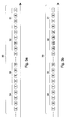
- Cell flow 30 is divided into groups, of which groups 31, 32, 33, and 34 are presented in Figs. 3a and 3b, comprising four cells each.
- the invention does not actually require the groups to contain an equal number of cells or to be in sequential order, but the size of the groups may vary and they can overlap in different ways in the cell flow. However, it is easiest to understand the invention in the form presented in Figs. 3a and 3b.
- the first cell of groups 31-34 (the right-hand cell in the Figs.) is a so-called counter cell, whereby its GFC bits (not shown separately in the Figs.) contain a serial number which, presented as a number in the decimal system, is no less than 1 and no greater than 15.
- the GFC bits in the other cells of the groups are zeros or the same as in the first cell of the group.
- the number in each cell in the figures presents the value of the GFC bits of the cell in question.
- the detection of the first cell of the group can be facilitated by setting the GFC bits to zeros in all other cells except the first cell of the group.
- a given value of the counter bits is understood to refer to the entire group of cells.
- the cells themselves do not have any knowledge of which cell in the group is concerned, so a reference to the number N cell within the group can only succeed if none of the N-1 first cells of the group have been lost and if the place of the cell that is referred to in the group has not changed.
- Both prerequisites are properties that are already required by the ATM system, and hence they do not impose unreasonable additional requirements on the reliability of the system.
- GFC bits it is not necessary to use GFC bits in particular to implement the counter. If certain conditions are met, it is possible to allocate some bits in the VPI and/or VCI fields for this purpose. Furthermore, it is possible to place, in the cell flow, special counter cells which use the payload to indicate the value of the counter.
- FIFO buffer 42 is provided in base station 40 between ATM protocol level 40a and MAC protocol level (Media Access Control) 40b. Sequential downlink ATM cells can be stored in the FIFO buffer. They are sent one by one to mobile unit 41 which acknowledges the successfully-received cells.
- the acknowledgment messages are abbreviated ACK (Acknowledge), according to general practice, and the lack of an acknowledgment message or a message that indicates an unsuccessful reception is abbreviated NACK (No-Acknowledge). A number or another identifier is added to each acknowledge message or no-acknowledge message, indicating the cell whose reception it is related to.
- This numbering is defined in the traffic protocol between the base station and the mobile unit and it does not necessarily have anything to do with the identification of ATM cells beyond the connection between base station 40 and mobile unit 41. The numbering does not even have to refer explicitly to given ATM cells, if the traffic between base station 40 and mobile unit 41 is performed in frames that are greater or smaller by one ATM cell. However, it is important from the point of view of the invention that base station 40 is able to determine explicitly, one way or another, with the aid of acknowledge messages ACK, NACK, which cells have been received successfully by mobile unit 41.
- Mobile unit 41 comprises a FIFO buffer 43 of downlink ATM cells between the ATM and MAC protocol levels. Cells are delivered from buffer 43 to the ATM level only after they have been acknowledged in the order of reception. Downlink ATM cells come from the network to FIFO buffer 42 of the base station and they are sent, between MAC levels 40b, 41b, to FIFO buffer 43 of the mobile unit.
- Fig. 4 presents mobile unit 41 which receives successfully cells 1 and 2 and acknowledges them, whereby they are cleared from both FIFO buffers, though in different senses: the clearing from buffer 43 of the mobile unit means that the cell is transferred to ATM level 41a, but the clearing from buffer 42 in the base station means that the cell is deleted.
- the reception of cell 3 fails, and hence it does not appear in buffer 43 of the mobile unit and it cannot be cleared from buffer 42 of the base station.
- the reception of the fourth cell succeeds but it cannot be cleared from buffer 42 of the base station because the third cell has not been cleared.
- the fourth cell is not delivered to ATM layer 41a in mobile unit 41 because the third cell was skipped from therebetween. A handover is effected after this, where the mobile unit sends to the base station a LAST(2) message that describes the last successfully-received and forwarded cell.
- old base station 40 transmits to new base station 50 the cells that were in the FIFO buffer, in the manner presented in Fig. 5.
- Fig. 5 also presents ATM switch 51 which communicates with said base stations 40 and 50. After the handover, ATM switch 51 directs the ATM cells sent to mobile unit 41 to new base station 50; but before they are sent to the mobile unit, the new base station receives from old base station 40 the three cells that were in its FIFO buffer and transmits those.
- the ATM cells need not to be identified separately in the traffic between base stations 40 and 50 and ATM switch 51, as long as the base stations continue, in the manner described above, to recognize which cells have been received successfully and in the right order in the mobile unit, and which cells are 'old', i.e., cells that were transferred from elsewhere as untransmitted cells, and which cells are 'new', i.e., cells that were received directly from ATM switch 51. All cells are directed sequentially from the ATM switch either to the old or to the new base station, and all the cells that the mobile unit was unable to receive successfully in the right order through the old base station are forwarded in the right order from the old base station to the new one to be transmitted before those cells that were directed to the new base station originally. In this way, it is possible to avoid packet loss and out-of-ordering during handover.
- the ATM switch 51 presented in the figure does not need to have a direct wired connection to the base stations 40 and 50 but it can be located at a longer distance in the network. In this case there can be other switches and nodes of the network between the ATM switch and the base stations. Moreover, the data transmission between base stations 40 and 50 is not necessarily performed directly.
- Mobile unit 41 comprises a transmission buffer (not shown separately in the figures) from which the transmitted ATM cells are cleared only after the old base station has sequentially acknowledged to have received them correctly. Since the wired connections between base stations 40 and 50 and ATM switch 51 are very reliable compared to wireless connections, it is fairly certain that the cells are transmitted with reasonable reliability from the base stations to the ATM switch. During a handover, the mobile unit transmits, through the new base station, all the cells that have not yet been cleared from the transmission buffer.
- ATM switch 51 can comprise or use the method described in Finnish patent application "The Use of Header Fields of ATM Cells in Wireless ATM Data Transmission” (Applicants: Nokia Mobile Phones and Nokia Telecommunications, Inventor: Kristian Rauhala) which was filed simultaneously with this application.
- Old base station 40 first sends to ATM switch 51 the uplink cells it has received in a normal manner.
- old base station 40 reports this to ATM switch 51 by means of a special UpReady message which is designated the letter U in Fig. 6.
- the purpose of the message is to tell the ATM switch that no more cells will be transmitted through old base station 40.
- Message U may be an ATM message cell of a specific type, it can be incorporated in the header of a data cell, or it can be transmitted as some other type of signaling between base station 40 and ATM switch 51.
- the same message can be transmitted as such to new base station 50 or base station 50 can be permitted by means of other type of signaling, to transmit cells received from mobile unit 41 to ATM switch 51.
- the U message cannot be sent from old base station 40 until after the last successfully-transmitted uplink cell and it has to be bound to the cell flow in such a manner that there is no risk of the cells transmitted by new base station 50 from preceding, in the sequence of transmission, the cells sent by old base station 40.
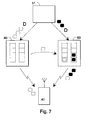
- Fig. 7 presents an equivalent procedure for downlink signaling.
- the idea is that ATM switch 51 decides from which point it starts directing downlink cells to new base station 50 instead of old base station 40.
- the last cell sent to old base station 40 is indicated by a so-called DownReady message which is designated D in Fig. 7.
- message D is bound to the cells of the downlink cell flow. It can be, e.g., a given ATM message cell (such as an RM, Resource Management cell), or it can be included in a field in the header of the last data cell.
- the same or a corresponding message D indicates the first cell of the cells transmitted to new base station 50.
- Old base station 40 attempts to send all the cells received before message D to mobile unit 41.
- a procedure similar to the one described above with reference to Fig. 4 can be used, or a method similar to the one described with reference to Figs. 3a and 3b. If old base station 40 is unable to send all the cells sequentially, it transmits the cells left in the transmission buffer to new base station 50. Finally, it transmits a message indicating that the downlink trans-mission buffer is empty; the message can be the same as message D.
- New base station 50 first sends the cells received from the old base station and only after that the cells that have come directly from ATM switch 51. The synchronized location of messages D in the cell flow directed to both the old and the new base stations guarantees that downlink cells are not lost and their sequence does not change.
- this embodiment presents a principle according to which the mobile unit decides the handover moment in the downlink data transmission. It is assumed that mobile unit 41 is moving from the transmission range of old base station 40 to that of new base station 50, which has been observed in the cellular system in a manner known per se. Now ATM switch 51 starts to duplicate downlink cells and sends them as cell flows to both base stations. The idea is that the base stations store the cells they receive in FIFO transmission buffers 42 and 52 which can be reset. Only one base station (that is, the old base station 40 first) sends cells to mobile unit 41 which acknowledges the cells received successfully and in the right order.
- ATM switch 51 adds counter messages into the cell flow, designated letter C and a serial number in Fig. 8.
- the counter messages have to be fixed in a given place with respect to the cells of the downlink cell flow. They can be, for example, given ATM message cells (such as RM cells, Resource Management) or they can be included in the header of a data cell. Each counter message C1, C2, etc. can be identified uniquely.
- old base station 40 After old base station 40 has transmitted successfully and in the right order all the cells that preceded a given counter message C1, it sends a message reporting this to new base station 50 in the form of signaling or in another manner known per se. As a response to the message, the new base station resets its FIFO buffer 52, i.e., deletes from it all the cells received from the ATM switch before counter message C1. This is repeated until mobile unit 41 does not acknowledge sequentially that it has received a given cell through the old base station. Old base station 40 then informs the new one as to where in the transmission it left off, by means of a message such as: '13th cell as counted from counter message C2 has not been sent'. New base station 50 deletes counter message C2 and the next 12 cells from transmission buffer 52 and starts transmitting from the 13th cell.
- the counter messages can comprise a serial number with a fairly long repetition cycle so as to avoid confusion.
- the counter messages can comprise a serial number with a fairly long repetition cycle so as to avoid confusion.
- the advantage is achieved that they can be buffered by the same means as the data cells.
- the general specifications of the ATM system ensure that the place of the counter messages in the cell flow does not change.
- the uplink communications in the embodiment presented in Fig. 8 can be implemented as a mirror image of the downlink communications, whereby both base stations 40 and 50 receive cells sent by mobile unit 41, but only one of them forwards the cells to ATM switch 51. Consequently, the counter messages are formed in mobile unit 41.
- the base station with 'the responsibility to send' has sent all the cells received before a given counter message, it notifies the other base station on this and the base station empties its uplink buffer as a response to this information.
- the old base station informs the new base station as to how many cells have been forwarded since the latest counter message, whereby the new base station continues the data transmission from the corresponding point.
- Embodiments of the invention are described above mainly with reference to two base stations.
- Present cellular systems use methods that can predict the next probable base station of a mobile unit, so this can be reported by means of signaling to the base stations participating in the operation.
- the methods described above can also be applied in systems which comprise several probable new base stations, and in systems in which it is not possible to predict the new base station. In these cases, it may be necessary to handle all the new base stations that are tangent to or intersect the transmission range of the old base station as probable new base stations.
- the base station of the radio data transmission system comprises, according to the figures, memory or buffer entities 42, 52 for temporarily storing the cells.
- the memory entities must be controllable so that the cells stored in them can be dealt with separately, for instance, forwarded or cleared from the buffer, and so that a given number of cells at a time can be cleared from them.
- the relative order of the cells must remain the same for the period of the storing and the memory entities must operate rapidly enough so that cells that are transmitted at a normal rate do not pile up in the base station.
- the implementation of such memory entities is known as such by those skilled in the art.
- the base station according to the invention comprises a means for transmitting cell-oriented data to another base station and for receiving data from that base station during handover.
- the cell-oriented data involves either the actual transmission of cells, as in the embodiments of Figs. 5, 6, and 7, or the transmission of data on a cell which, as counted from a given counter message, was being processed at the time of terminating the radio link between the base station and the mobile unit.
- the formation, the transmission, and the reception of cell-oriented data can preferably be implemented as a programmable process carried out by the block that controls the operation of the base station, whereby known components and programming methods are used to implement it.
- the radio data transmission system comprises at least one switch 51 and at least two base stations 40 and 50 according to the invention, as described above.
- Mobile unit 41 can also be considered part of the data transmission system because without it the user would be unable to make use of the properties of the system.
- a data link is provided between the base stations for transmitting cell-oriented data during handover. It is preferable to implement the data transmission as a wired connection and it can be effected directly between the base stations or it can be transmitted through switching device 51.
- the handover has been mainly explained with reference to a case in which an individual mobile unit migrates.
- the invention can be implemented, on more general terms, in a data transmission system comprising at least one radio link segment.
- the mobile unit of the preceding description can actually be a network representative that handles, on the one hand, the wireless connection to the base stations and, on the other hand, the wired connections to the parts of the network that are located in their own subordination.
- a handover might be necessary for reasons other than the migration of the mobile unit. It can be used, for example, to balance out the load in the different parts of the network or it can be caused by a temporary disruption which weakens the capacity of the old base station.
- the mobile unit can, of course, simply be a separate, portable mobile unit.
- a mobile station segment which can be, for example, a mobile phone of a digital cellular network (such as a GSM telephone) or a wireless digital telephone (such as a DECT telephone), and of a computer segment which is in local connection with the said mobile station segment and which can be, e.g., a laptop computer.
- the said local connection can be a wired connection or an infrared connection.
- the invention discloses a method and equipment in which the risk of packet loss and/or of out-of-ordering during handover is diminished to a significantly great extent by means of transmitting, between the new and the old base stations, information on which cells are successfully transmitted and/or received across the radio interface before the handover.
- the invention can be applied to create an effective ATM network solution that comprises connection segments of which at least one is wireless.
Abstract
Description
- The invention generally relates to procedures aimed at maintaining the reliability of data transmission in wireless telecommunications systems comprising several base stations, and in particular to maintaining the composition of the data carried in data cells during a handover in a system which transfers data as data cells whose relative order is significant.
- The ATM (Asynchronous Transfer Mode) is a strong candidate for a fast future transfer protocol in B-ISDN networks (Broadband Integrated Services Digital Network), for example, and generally in communications between data transmission devices. The network consists of nodes and terminals, and of links between them. In an ATM network, data is transferred as cells in digital form, each cell comprising a so-called payload of 48 bytes and a header of 5 bytes. In order for the amount of the header information to be kept at a minimum, the headers do not contain complete routing information between the transmitting and the receiving devices but only information on the virtual path and channel in which the respective data transfer connection is carried. The nodes of the network contain the necessary routing information on the basis of which the respective identifiers of the virtual path and channel are interpreted as a reference for the next respective node. The relative order of the cells must remain the same throughout the transmission because there is no specific mechanism in the ATM network that can be used to rearrange out-of-order cells.
- Traditionally, ATM-links have been conceived as wired circuits or optical cable connections, whereby the above-mentioned requirement of the relative order of the cells has not caused major problems. However, it is anticipated that the terminals of future data transfer solutions must have the same kind of mobility and independence of permanent connections as mobile phones of cellular networks already have. Because of its effectiveness and the provision to flexibly modify it, the cellular radio network is a likely architecture in the future. A typical cellular network comprises several base stations (BS) which are affiliated with - possibly through a base station controller (BSC) - a mobile switching center (MSC). In a large cellular network there are numerous mobile switching centers as well as base stations and base station controllers that work under the mobile switching centers. The transmission range of each base station, i.e., the geographical area where the terminals can communicate wirelessly with the said base station, is called a cell.
- However, to avoid confusion, the term cell is in this patent application used to refer only to the transferred data unit defined by a given data transmission system, the length of the unit being the above-mentioned 53 bytes in the ATM system which is used as an example.
- A typical phenomenon of cellular systems is the change of base stations, i.e., the handover, where a given mobile terminal moves from the transmission range of a first base station to that of a second base station, whereby essentially all the data transmission between the terminal in question and the network is rerouted through the new base station. A perfect synchronization of the operation during the handover is often not possible, which may result in packet loss, duplication or misordering. This is especially severe in the ATM system where a successful transmission of all the cells and ordering are a prerequisite for effective data transmission.
- A handover may take place without a notice or with a notice. The former refers to a situation where the connection between the base station and the terminal breaks quickly and the latter implies that, where the connection worsens gradually, one can prepare for procedures required for handover. The doctoral thesis of S. K. Biswas "Handling Realtime Traffic in Mobile Networks" (University of Cambridge, September 1994) discloses procedures for implementing a handover both without a notice and with a notice. In order to explain the background of the invention, the handover of base stations is described briefly in the following with reference to Figs. 1 and 2.
- Fig. 1 presents the mobile unit MU, two base stations BSp and BSq, and mobile representative MR which is in charge of routing the traffic between the said base stations and the rest of the data transmission network. In addition, the data transfer segments between the said devices are designated letters i, j, k, and 1. The data transfer segment directed from mobile representative MR to the rest of the network is designated s. The data directed from mobile unit MU to the network is called uplink data and the data propagating in the opposite direction is called downlink data.
- Fig. 2 presents signals between the said devices by means of numbered arrows, relating to the handover with a notice in which BSp is the old base station and BSq is the new base station. Mobile unit MU stops transmitting uplink cells along segment i and transmits initiate
message 21 to new base station BSq. BSq transmitsforward message 22 to mobile representative MR on the need to reroute. As a response, mobile representative MR stops sending downlink data, which arrives along segment s, to old base station BSp along segment k, and directs it to new base station BSq throughsegment 1. Before transmitting the actual data to be transmitted, mobile representative MR transmitsreply message 23 which is forwarded to the mobile unit asack message 24 by base station BSq. At the same time, the new base station creates a temporary FIFO buffer (first in, first out) 25 for storing the downlink data that comes from mobile representative MR. It is not until mobile unit MU believes it has received all the downlink data which had been directed from mobile representative MR via segment k to old base station BSp before switching the connection tosegment 1, that it transmits donemessage 26 to new base station BSq and starts to transmit uplink data. As a response to done 26, new base station BSq starts sending downlink data (by first unloading buffer 25) and, for its part, finishes the handover by sendingcomplete message 27 to mobile representative MR. - The connection from mobile representative MR to old base station BSp can be terminated by using a ready message immediately after the data transfer connection of segment k has been broken off (arrow 28), or once
ready message 27 has arrived (arrow 29). For the sake of clarity, Fig. 2 presents the interrupt time of the uplink data, represented by a shaded bar, the interrupt time of the downlink data in mobile representative MR, represented by a black bar, and the interrupt time of the downlink data in new base station BSq, represented by a white bar. - According to Biswas, the handover without a notice comprises several similar procedures, but disruptions in data transmission can be longer because delay is caused in the time spent before a break is detected in the connection passing through the old base station. In both the arrangements, the one with a notice and the one without a notice, it is possible that there is packet loss or packet misordering. In the case of uplink data, it is possible that mobile representative MR breaks off the data transmission from segment k to the network before all the uplink cells have been transmitted across segments i and k. After the connection is terminated, the cells in question are considered lost, or if they are still directed to the network, they can be out of order in the uplink. The downlink cells, which have been directed to segments k and i before the handover, may be lost altogether because of a weak radio link, or they can arrive late in mobile unit MU, causing out-of-ordering in the downlink.
- Packet loss and out-of-ordering usually results in that an erroneous checksum or other indicator is detected on a higher protocol level, whereby a given protocol data unit (PDA) comprising several cells is denied and requested to be sent again. This is uneconomic from the point of view of the network resource utilization.
- Patent publication EP 426 269 to British Telecommunications discloses a method in which the base stations are assembled in groups of several base stations. To facilitate and speed up the handover, all the cells directed to a mobile unit in the transmission range of a given base station are sent to all the base stations of the same group by means of the data transmission network. The publication presents an idea according to which the old base station sends all the cells delivered to it, and after this, the new base station starts sending the cells delivered through it. The publication also presents a predictor which is incorporated in the base station controller or in the mobile representative that controls the base stations. The task of the predictor is to monitor the movement of the mobile unit from one transmission range to another and to estimate as to where the mobile unit will migrate next. This is effected in order to decrease the amount of cells sent unnecessarily to the remotest base stations of the group. However, the solution cannot maintain packet ordering or prevent packet loss because the old and the new base stations cannot tell precisely which cells have been transmitted and received correctly immediately before or after the handover.
- Patent publication EP 366 342 to AT&T discloses a method in which data is transmitted as cells in a cellular radio network and the header segment of each cell comprises an unchanging segment which remains unmodified regardless of the changes in routing, and a changing segment whose contents vary during a handover or during other rerouting processes. The publication suggests that the arrangement can be used to facilitate the handover, but only the definition of the routing is benefited. A similar method is disclosed in patent publication EP 577 959 to Roke Manor Research Ltd., relating to the ATM network in particular. In this case, the unchanging segment in the cell header is a so-called VCI field (Virtual Channel Identifier) and the changing segment is a so-called VPI field (Virtual Path Identifier). Neither one of the publications discloses a method which could ensure that packet ordering remains the same and/or which could prevent packet loss during the handover.
- Patent publication EP 577 960 to Roke Manor Research Ltd. discloses a method in which at least one of the base stations of a cellular network is affiliated, through the ATM network, with at least two mobile representatives which, in the disclosed arrangement, also function as repeaters between the ATM network and a fixed telephone network. The idea is to arrange the VPIs and the VCIs of the ATM network which control the routing so that even though a given mobile unit moves into the transmission range of another mobile representative (or mobile services switching center), the routing is implemented by linking via the original mobile representative. The arrangement has some advantages in decreasing the amount of switchings in the network but it does not have an effect on packet loss between the base stations and the mobile unit and/or on the delay of cells during a handover.
- The article "BAHAMA: A Broadband Ad-Hoc Wireless ATM Local-Area Network", Proc. ICC '95, 18-22 June 1995, Seattle, written by K. Y. Eng et al., discloses a method in which the GFC field in the header segments of ATM cells is used to implement cell-oriented sequential numbering. The purpose is to contribute to the synchronization and combination of steams of cells that arrive at a given conjuction point along two parallel routes. The purpose in numbering the cells is aimed particularly at identifying them unequivocally, so that cells are not duplicated or lost when the streams of cells are combined and their order will remain the same. In this case, a problem might occur because only numbers from 0 to 15 can be presented in the GFC field which has a maximum of four bits, whereby the numbering cycle remains so short that cells with the same number belonging to subsequent cycles may become out-of-ordered.
- The object of the present invention is to provide a method that diminishes the likelihood of packet loss and out-of-ordering in a radio interface during a handover. Another object of the invention is to present a data transmission system comprising a means of preventing or decreasing packet loss and out-of-ordering during the handover. Another object of the invention is that the method and system disclosed do not require major changes in the specified ATM and B-ISDN systems.
- The objects of the invention are accomplished by a method which can be used to refer to the cells of the system with an accuracy of at least a given number of cells, so that the base stations can exchange information on which cells have been sent and/or received successfully during the handover.
- The method according to the invention for performing handover processes in a system that applies cellular data transmission and comprises a switch, a first and a second base station and a mobile unit, is characterized in that the first base station provides the switch and/or the second base station with information on which cells have been successfully transmitted between the first base station and the mobile unit, so that the transmission of cells continues between the second base station and the mobile unit, beginning with the first cell that has not been successfully transmitted between the first base station and the mobile unit.
- The invention is further related to the base station of a wireless data transmission system. The base station according to the invention is characterized in comprising a means for dispatching information to other base stations on which cells have been transmitted successfully and in the right order between the base station and the mobile unit, and a means for receiving the corresponding information from the other base stations.
- The invention is further related to a data transmission system. The data transmission system according to the invention is characterized in comprising a means for transmitting messages between the base station on the cells of the transferred cellular data.
- The invention is based on the insight according to which the base stations may well exchange data on the success of the transmission and/or the reception of cells, even though the specifications of the data transmission system do not support the reference to discrete cells per se. In this case, synchronization mechanisms can be provided in a manner described below, by means of which the old and the new base stations participating in the handover share information on which cells have been successfully transmitted to the mobile unit and/or received from there. On the basis of the successful transmission of cells, the point in the stream of cells from where the transmission is to be continued can be indicated to the new base station. In addition, the cells that were not transmitted and/or received via the old base station can be designated to be sent and/or received through the new base station.
- In the following, the ATM system is dealt with as an exemplary object of application of the invention, the system being characterized in a high data transfer rate, the relatively small size of cells, and the small number of available cell header fields which is due to stringent specifications. However, it will be appreciated by those skilled in the art that the invention can also be applied in other data transmission methods and systems whose specifications do not support the reference to discrete cells per se and/or in which it is important not to lose any cells and to maintain their relative order.
- The direction of the data transmission from the network through the base station to the mobile unit is called downlink, according to the established practice, and the opposite direction is called uplink. The old and the new base stations participate in the handover. Downlink data is transmitted through the old base station until the moment of the handover, after which the old base station informs the new one that it has terminated downlink data transmission and sends those buffered cells that had perhaps not been transmitted, to the new base station or informs it about which cells are involved. The latter situation applies when the base stations have received the same cells from the network as a preliminary procedure for the handover. Similarly, the uplink data is transferred through the old base station until the moment of the handover and, after the handover, the old base station sends a message of terminating the uplink data transmission. The base stations can receive the same cells from the direction of the mobile unit as a preliminary procedure for the handover. In this case, the old base station informs the new one as to which uplink cells have been forwarded, so that the new base station will not send the same cells again. The handover on uplink and downlink data transmission does not necessarily occur simultaneously in the method according to the invention.
- The cells of the exemplary ATM system comprise four header field bits whose use is defined so freely that they are available for the implementation of the cell reference system. Taking into account the shortness of the cells and the rapidity of the ATM system, it is not practical to number all the sequential cells with a serial number of four bits because the numbering, in any case, winds back to zero after every sixteenth cell. A fast repeating of the counter cycle might cause confusion as to which of the sequential cycles is in question. Instead, a counter can be implemented whose value deviates from zero only in one cell per group of cells of a given length, whereby a given value of the counter can be used to refer to the whole group of cells, and discrete signaling can even be used to designate one cell in the group.
- In the following, the invention is described in detail with reference to the preferred embodiments presented as examples and to the appended drawings in which:
- Fig. 1 presents a known data transmission system with two base stations,
- Fig. 2 presents a known data transmission protocol in the data transmission system of Fig. 1,
- Fig. 3a presents a given cell reference process according to a preferred embodiment of the invention,
- Fig. 3b presents a reference to a group of cells in the process according to Fig. 3a,
- Fig. 4 presents the affiliation between a base station and a mobile unit in the method according to a preferred embodiment of the invention,
- Fig. 5 presents the affiliation between the old and the new base stations and an ATM switch in the method according to the embodiment of Fig. 4,
- Fig. 6 presents the affiliation between the ATM switch, two base stations, and a mobile unit, according to another preferred embodiment of the invention,
- Fig. 7 presents downlink communication in the embodiment of Fig. 6, and
- Fig. 8 presents downlink communication in another embodiment of the invention.
- Reference was made above to Figs. 1 and 2 in connection with the description of prior art. Therefore, in the following description of the invention and its advantageous embodiments, reference is made mainly to Figs. 3a-8. Identical reference numbers are used in the figures for corresponding parts.
- First, a cell reference process according to an advantageous embodiment of the invention is described with reference to Figs. 3a and 3b. The header of an ATM cell comprises, as known by those skilled in the art, four so-called GFC bits, (Generic Flow Control) which are defined so that they can be used to implement a cell reference counter according to the invention.
Cell flow 30 is divided into groups, of whichgroups - The first cell of groups 31-34 (the right-hand cell in the Figs.) is a so-called counter cell, whereby its GFC bits (not shown separately in the Figs.) contain a serial number which, presented as a number in the decimal system, is no less than 1 and no greater than 15. The GFC bits in the other cells of the groups are zeros or the same as in the first cell of the group. The number in each cell in the figures presents the value of the GFC bits of the cell in question. The detection of the first cell of the group can be facilitated by setting the GFC bits to zeros in all other cells except the first cell of the group. A given value of the counter bits is understood to refer to the entire group of cells. A reference can be made separately to a given cell within the group by stating which cell is in question as counted from the beginning of the group. The cells themselves do not have any knowledge of which cell in the group is concerned, so a reference to the number N cell within the group can only succeed if none of the N-1 first cells of the group have been lost and if the place of the cell that is referred to in the group has not changed. Both prerequisites are properties that are already required by the ATM system, and hence they do not impose unreasonable additional requirements on the reliability of the system.
- Fig. 3a presents a shaded cell which is identified by means of the definition 'counter=2, third cell'. In Fig. 3b, the entire group of cells is referred to by means of the definition 'counter=2'. Since there are several cells in the group, the resetting of the counter to the beginning (cf.
groups 31 and 34) takes a great deal longer than if each cell is numbered separately with a serial number from 0-15. The group-oriented numbering decreases the risk of confusion which is otherwise caused by the relatively short cycle of the reset of the counter and by the fact that there can be several hundred cells simultaneously in a given buffer. - It is not necessary to use GFC bits in particular to implement the counter. If certain conditions are met, it is possible to allocate some bits in the VPI and/or VCI fields for this purpose. Furthermore, it is possible to place, in the cell flow, special counter cells which use the payload to indicate the value of the counter.
- In the following, traffic according to a preferred embodiment of the invention between a given base station and a mobile unit with which it is affiliated is described with reference to Figs. 4 and 5. Several acknowledgment methods are known in prior art which attempt to ensure that each segment of data that is transmitted in parts is sent successfully to the receiving device. These methods are often either so-called selective methods or methods of the go-back-N-type. The former implies that if the transmitting device sends ten packets, for example, of which the receiving device handles successfully all but the seventh one, it requests, in the form of an acknowledgment, the transmitter to send only the seventh packet again. In a go-back-N-type method, the receiver requests the transmitter to start the entire transmission again starting from the seventh packet. In the case presented in Fig. 4, any acknowledgment method can be applied between
base station 40 andmobile unit 41 during normal traffic. When a handover is imminent, a special acknowledgment message that describes the last successfully-received cell of the sequence is activated in addition to or instead of the acknowledgment method. -
FIFO buffer 42 is provided inbase station 40 betweenATM protocol level 40a and MAC protocol level (Media Access Control) 40b. Sequential downlink ATM cells can be stored in the FIFO buffer. They are sent one by one tomobile unit 41 which acknowledges the successfully-received cells. The acknowledgment messages are abbreviated ACK (Acknowledge), according to general practice, and the lack of an acknowledgment message or a message that indicates an unsuccessful reception is abbreviated NACK (No-Acknowledge). A number or another identifier is added to each acknowledge message or no-acknowledge message, indicating the cell whose reception it is related to. This numbering is defined in the traffic protocol between the base station and the mobile unit and it does not necessarily have anything to do with the identification of ATM cells beyond the connection betweenbase station 40 andmobile unit 41. The numbering does not even have to refer explicitly to given ATM cells, if the traffic betweenbase station 40 andmobile unit 41 is performed in frames that are greater or smaller by one ATM cell. However, it is important from the point of view of the invention thatbase station 40 is able to determine explicitly, one way or another, with the aid of acknowledge messages ACK, NACK, which cells have been received successfully bymobile unit 41. -
Mobile unit 41 comprises aFIFO buffer 43 of downlink ATM cells between the ATM and MAC protocol levels. Cells are delivered frombuffer 43 to the ATM level only after they have been acknowledged in the order of reception. Downlink ATM cells come from the network toFIFO buffer 42 of the base station and they are sent, betweenMAC levels FIFO buffer 43 of the mobile unit. Fig. 4 presentsmobile unit 41 which receives successfullycells buffer 43 of the mobile unit means that the cell is transferred toATM level 41a, but the clearing frombuffer 42 in the base station means that the cell is deleted. The reception ofcell 3 fails, and hence it does not appear inbuffer 43 of the mobile unit and it cannot be cleared frombuffer 42 of the base station. The reception of the fourth cell succeeds but it cannot be cleared frombuffer 42 of the base station because the third cell has not been cleared. The fourth cell is not delivered toATM layer 41a inmobile unit 41 because the third cell was skipped from therebetween. A handover is effected after this, where the mobile unit sends to the base station a LAST(2) message that describes the last successfully-received and forwarded cell. - As a response to the LAST message and to the signaling data on the handover that indicate the new base station,
old base station 40 transmits tonew base station 50 the cells that were in the FIFO buffer, in the manner presented in Fig. 5. Fig. 5 also presentsATM switch 51 which communicates with saidbase stations ATM switch 51 directs the ATM cells sent tomobile unit 41 tonew base station 50; but before they are sent to the mobile unit, the new base station receives fromold base station 40 the three cells that were in its FIFO buffer and transmits those. The ATM cells need not to be identified separately in the traffic betweenbase stations ATM switch 51, as long as the base stations continue, in the manner described above, to recognize which cells have been received successfully and in the right order in the mobile unit, and which cells are 'old', i.e., cells that were transferred from elsewhere as untransmitted cells, and which cells are 'new', i.e., cells that were received directly fromATM switch 51. All cells are directed sequentially from the ATM switch either to the old or to the new base station, and all the cells that the mobile unit was unable to receive successfully in the right order through the old base station are forwarded in the right order from the old base station to the new one to be transmitted before those cells that were directed to the new base station originally. In this way, it is possible to avoid packet loss and out-of-ordering during handover. - Referring to Fig. 5, it is to be noted that the
ATM switch 51 presented in the figure does not need to have a direct wired connection to thebase stations base stations - Essentially, the handling of uplink cells in the embodiment of Figs. 4 and 5 is effected as a mirror image of the handling of downlink cells.
Mobile unit 41 comprises a transmission buffer (not shown separately in the figures) from which the transmitted ATM cells are cleared only after the old base station has sequentially acknowledged to have received them correctly. Since the wired connections betweenbase stations ATM switch 51 are very reliable compared to wireless connections, it is fairly certain that the cells are transmitted with reasonable reliability from the base stations to the ATM switch. During a handover, the mobile unit transmits, through the new base station, all the cells that have not yet been cleared from the transmission buffer. To synchronize the cells received from the old and the new base stations,ATM switch 51 can comprise or use the method described in Finnish patent application "The Use of Header Fields of ATM Cells in Wireless ATM Data Transmission" (Applicants: Nokia Mobile Phones and Nokia Telecommunications, Inventor: Kristian Rauhala) which was filed simultaneously with this application. - In the following, another preferred embodiment of the invention is described with reference to Figs. 6 and 7.
Old base station 40 first sends to ATM switch 51 the uplink cells it has received in a normal manner. When the radio link tomobile unit 41 is lost,old base station 40 reports this to ATM switch 51 by means of a special UpReady message which is designated the letter U in Fig. 6. The purpose of the message is to tell the ATM switch that no more cells will be transmitted throughold base station 40. Message U may be an ATM message cell of a specific type, it can be incorporated in the header of a data cell, or it can be transmitted as some other type of signaling betweenbase station 40 andATM switch 51. The same message can be transmitted as such tonew base station 50 orbase station 50 can be permitted by means of other type of signaling, to transmit cells received frommobile unit 41 toATM switch 51. The U message cannot be sent fromold base station 40 until after the last successfully-transmitted uplink cell and it has to be bound to the cell flow in such a manner that there is no risk of the cells transmitted bynew base station 50 from preceding, in the sequence of transmission, the cells sent byold base station 40. - Fig. 7 presents an equivalent procedure for downlink signaling. The idea is that
ATM switch 51 decides from which point it starts directing downlink cells tonew base station 50 instead ofold base station 40. The last cell sent toold base station 40 is indicated by a so-called DownReady message which is designated D in Fig. 7. To maintain the order of the cells, it is important that message D is bound to the cells of the downlink cell flow. It can be, e.g., a given ATM message cell (such as an RM, Resource Management cell), or it can be included in a field in the header of the last data cell. The same or a corresponding message D indicates the first cell of the cells transmitted tonew base station 50.Old base station 40 attempts to send all the cells received before message D tomobile unit 41. For identifying the successfully-transmitted cells, a procedure similar to the one described above with reference to Fig. 4 can be used, or a method similar to the one described with reference to Figs. 3a and 3b. Ifold base station 40 is unable to send all the cells sequentially, it transmits the cells left in the transmission buffer tonew base station 50. Finally, it transmits a message indicating that the downlink trans-mission buffer is empty; the message can be the same as message D.New base station 50 first sends the cells received from the old base station and only after that the cells that have come directly fromATM switch 51. The synchronized location of messages D in the cell flow directed to both the old and the new base stations guarantees that downlink cells are not lost and their sequence does not change. - In the following, another preferred embodiment of the invention is described with reference to Fig. 8. As a distinction to the one described above, this embodiment presents a principle according to which the mobile unit decides the handover moment in the downlink data transmission. It is assumed that
mobile unit 41 is moving from the transmission range ofold base station 40 to that ofnew base station 50, which has been observed in the cellular system in a manner known per se. Now ATM switch 51 starts to duplicate downlink cells and sends them as cell flows to both base stations. The idea is that the base stations store the cells they receive in FIFO transmission buffers 42 and 52 which can be reset. Only one base station (that is, theold base station 40 first) sends cells tomobile unit 41 which acknowledges the cells received successfully and in the right order. If successful communication through the old base station continues for long and more and more cells arrive, an unreasonably big buffer is required in the new base station. To avoid this,ATM switch 51 adds counter messages into the cell flow, designated letter C and a serial number in Fig. 8. The counter messages have to be fixed in a given place with respect to the cells of the downlink cell flow. They can be, for example, given ATM message cells (such as RM cells, Resource Management) or they can be included in the header of a data cell. Each counter message C1, C2, etc. can be identified uniquely. - After
old base station 40 has transmitted successfully and in the right order all the cells that preceded a given counter message C1, it sends a message reporting this tonew base station 50 in the form of signaling or in another manner known per se. As a response to the message, the new base station resets its FIFO buffer 52, i.e., deletes from it all the cells received from the ATM switch before counter message C1. This is repeated untilmobile unit 41 does not acknowledge sequentially that it has received a given cell through the old base station.Old base station 40 then informs the new one as to where in the transmission it left off, by means of a message such as: '13th cell as counted from counter message C2 has not been sent'.New base station 50 deletes counter message C2 and the next 12 cells from transmission buffer 52 and starts transmitting from the 13th cell. - The method used to uniquely identify counter messages C1, C2, etc., is not essential to the invention. As indicated in the name, the counter messages can comprise a serial number with a fairly long repetition cycle so as to avoid confusion. By including the counter messages in ATM cells of a normal form, the advantage is achieved that they can be buffered by the same means as the data cells. In addition, the general specifications of the ATM system ensure that the place of the counter messages in the cell flow does not change.
- The uplink communications in the embodiment presented in Fig. 8 can be implemented as a mirror image of the downlink communications, whereby both
base stations mobile unit 41, but only one of them forwards the cells toATM switch 51. Consequently, the counter messages are formed inmobile unit 41. When the base station with 'the responsibility to send' has sent all the cells received before a given counter message, it notifies the other base station on this and the base station empties its uplink buffer as a response to this information. When the connection between the old base station and the mobile unit is terminated, the old base station informs the new base station as to how many cells have been forwarded since the latest counter message, whereby the new base station continues the data transmission from the corresponding point. - Embodiments of the invention are described above mainly with reference to two base stations. Present cellular systems use methods that can predict the next probable base station of a mobile unit, so this can be reported by means of signaling to the base stations participating in the operation. However, it will be appreciated by those skilled in the art that the methods described above can also be applied in systems which comprise several probable new base stations, and in systems in which it is not possible to predict the new base station. In these cases, it may be necessary to handle all the new base stations that are tangent to or intersect the transmission range of the old base station as probable new base stations.
- Several embodiments are also described above which all present the operation in downlink and uplink communications. It is obvious that the protocols of downlink and uplink communications need not be combined as the pairs presented above but the embodiment of Fig. 8, for example, can be applied in downlink communications, and the embodiment of Fig. 6 can be applied in uplink communications in the same system. Furthermore, the methods according to the different embodiments of the invention can also be applied alternatively in the same system in the same direction of traffic, depending on the quality of the connection to be transmitted or on the load status of the network.
- The base station of the radio data transmission system according to the invention comprises, according to the figures, memory or
buffer entities 42, 52 for temporarily storing the cells. The memory entities must be controllable so that the cells stored in them can be dealt with separately, for instance, forwarded or cleared from the buffer, and so that a given number of cells at a time can be cleared from them. The relative order of the cells must remain the same for the period of the storing and the memory entities must operate rapidly enough so that cells that are transmitted at a normal rate do not pile up in the base station. The implementation of such memory entities is known as such by those skilled in the art. Furthermore, the base station according to the invention comprises a means for transmitting cell-oriented data to another base station and for receiving data from that base station during handover. As stated above, the cell-oriented data involves either the actual transmission of cells, as in the embodiments of Figs. 5, 6, and 7, or the transmission of data on a cell which, as counted from a given counter message, was being processed at the time of terminating the radio link between the base station and the mobile unit. The formation, the transmission, and the reception of cell-oriented data can preferably be implemented as a programmable process carried out by the block that controls the operation of the base station, whereby known components and programming methods are used to implement it. - The radio data transmission system according to the invention comprises at least one
switch 51 and at least twobase stations Mobile unit 41 can also be considered part of the data transmission system because without it the user would be unable to make use of the properties of the system. In the data transmission according to the invention, a data link is provided between the base stations for transmitting cell-oriented data during handover. It is preferable to implement the data transmission as a wired connection and it can be effected directly between the base stations or it can be transmitted through switchingdevice 51. - In the embodiments described above, the handover has been mainly explained with reference to a case in which an individual mobile unit migrates. However, the invention can be implemented, on more general terms, in a data transmission system comprising at least one radio link segment. This means that the mobile unit of the preceding description can actually be a network representative that handles, on the one hand, the wireless connection to the base stations and, on the other hand, the wired connections to the parts of the network that are located in their own subordination. Furthermore, a handover might be necessary for reasons other than the migration of the mobile unit. It can be used, for example, to balance out the load in the different parts of the network or it can be caused by a temporary disruption which weakens the capacity of the old base station.
- The mobile unit can, of course, simply be a separate, portable mobile unit. In this case, it most probably consists of a mobile station segment which can be, for example, a mobile phone of a digital cellular network (such as a GSM telephone) or a wireless digital telephone (such as a DECT telephone), and of a computer segment which is in local connection with the said mobile station segment and which can be, e.g., a laptop computer. The said local connection can be a wired connection or an infrared connection.
- The invention discloses a method and equipment in which the risk of packet loss and/or of out-of-ordering during handover is diminished to a significantly great extent by means of transmitting, between the new and the old base stations, information on which cells are successfully transmitted and/or received across the radio interface before the handover. The invention can be applied to create an effective ATM network solution that comprises connection segments of which at least one is wireless.
Claims (18)
- A method for implementing a handover in a data transmission system that comprises a switch (51) and a first (40) and a second (50) base station that are affiliated with the switch, and a mobile unit (41) that is affiliated wirelessly with the base stations, the data transmission system comprising the transmission of data as cells of a given size, and the handover comprising the transmission of data first between the mobile unit (41) and the first base station (40) and, after that, between the mobile unit (41) and the second base station (50), characterized in that the first base station (40) provides the switch (51) and/or the second base station (50) with information on which cells have been successfully transmitted between the first base station and the mobile unit.
- A method according to Claim 1, characterized in that the transmission of cells continues between the second base station and the mobile unit starting from the first unsuccessfully transmitted cell between the first base station and the mobile unit.
- A method according to Claim 1 or 2, characterized in that in the first (40) and the second (50) base stations, downlink cells are stored in a buffer (42, 52) before transmitting them to the mobile unit (41).
- A method according to Claim 3, characterized in that, when transmitting downlink cells from the first base station (40) to the mobile unit, the mobile unit (41) acknowledges the cells received successfully, whereby the downlink cells that are acknowledged as having been received successfully and in the right order are cleared from the buffer (42) of the first base station.
- A method according to Claim 4, characterized in that during a handover, the downlink cells, which have not been cleared from the buffer (42) of the first base station, are transmitted to the second base station (50) to be sent to the mobile unit (41).
- A method according to any of the preceding Claims, characterized in that the switch (51) adds a first message (D) to the transmission flow consisting of the downlink data cells to be transferred, the message (D) indicating the termination of the cells to be transmitted through the said first base station (40), and the start of the cells to be transmitted through the second base station (50), whereby the location of the first message (D) is fixed with respect to the downlink cells of said transmission flow.
- A method according to any of the preceding Claims, characterized in that the switch (51) adds counter messages (C1, C2) to the transmission flow comprised of downlink data cells to be transferred, the location of the counter messages being fixed with respect to said downlink cells of the transmission flow.
- A method according to Claim 7, characterized in that said counter messages (C 1, C2) comprise a serial number that has been added to given numbering cells and that deviates from the immediately preceding serial numbers, and there is, respectively, a predetermined number of cells between said numbering cells, belonging to the group of cells (31, 32, 33, 34) indicated by said serial number.
- A method according to Claim 7 or 8, characterized in that the switch (51) transmits the same cells both to the first (40) and to the second (50) base stations, whereby both base stations store said cells in the buffer (42, 52), and after the first base station (40) has successfully sent all the cells that preceded a given counter message (C1) to the mobile unit (41), it transmits another message that reports this to the second base station (50), and as a response to said second message, the second base station clears the corresponding cells from its buffer (52).
- A method according to any of the preceding Claims, characterized in that the uplink cells in the mobile unit (41) are stored in a buffer before transmission.
- A method according to Claim 10, characterized in that when transmitting uplink cells from the mobile unit (41) to the first base station (40), the base station acknowledges the successfully-received cells, whereby the uplink cells that are acknowledged to have been received successfully and in the right order are cleared from said buffer of the mobile unit.
- A method according to Claim 10 or 11, characterized in that the first base station (40) transmits, during the handover, a third message (U) to the switch (51), the message indicating the termination of the successfully transmitted cells through the first base station (40).
- A method according to any of the preceding Claims, characterized in that the mobile unit (41) adds counter messages to the transmission flow comprised of uplink data cells to be transferred, the location of the counter messages being fixed with respect to the uplink cells of said transmission flow.
- A method according to Claim 13, characterized in that said counter messages comprise a serial number that has been added to given numbering cells and that deviates from the immediately preceding serial numbers, and that there is, respectively, a predetermined number of cells between said numbering cells, belonging to the group of cells indicated by said serial number.
- A method according to Claim 13 or 14, characterized in that the mobile unit (41) sends the same uplink cells to both the first (40) and to the second (50) base stations, whereby both base stations store the said uplink cells in a buffer, and after the first base station (40) has successfully received all the cells that preceded a given counter message from the mobile unit (41), it transmits a fourth message reporting this to the second base station (50) and, as a response to said fourth message, the second base station (50) clears the corresponding cells from its buffer.
- A base station (40, 50) of a radio data transmission system for transmitting data in cell form between a switch (51) connected to the base station by means of a wired connection and a mobile unit (41) which is in radio link with the base station, characterized in comprising a means for delivering to other base stations the data on cells that are transmitted successfully and in the right order between the base station and the mobile unit, and a means for receiving the corresponding data from other base stations.
- A base station according to Claim 16, characterized in comprising a buffer entity (42, 52) for temporarily storing the data in cell form, and a means for selectively clearing cells from said buffer entity.
- A radio transmission system comprising a switch (51) for controlling data in cell form, and at least two base stations (40, 50) that are affiliated with it for transmitting the data in cell form between the switch (51) and the mobile unit (41), the mobile unit communicating wirelessly with the base stations, characterized in comprising a means for transmitting messages concerning the cells of the transferred data in cell form between the base stations.
Applications Claiming Priority (2)
| Application Number | Priority Date | Filing Date | Title |
|---|---|---|---|
| FI955812A FI101763B1 (en) | 1995-12-01 | 1995-12-01 | The retention of the transported information composition between base station switches |
| FI955812 | 1995-12-01 |
Publications (1)
| Publication Number | Publication Date |
|---|---|
| EP0777396A1 true EP0777396A1 (en) | 1997-06-04 |
Family
ID=8544476
Family Applications (1)
| Application Number | Title | Priority Date | Filing Date |
|---|---|---|---|
| EP96660078A Withdrawn EP0777396A1 (en) | 1995-12-01 | 1996-11-01 | Maintaining the composition of transferred data during handover |
Country Status (7)
| Country | Link |
|---|---|
| US (1) | US5940371A (en) |
| EP (1) | EP0777396A1 (en) |
| JP (1) | JPH09186704A (en) |
| CN (1) | CN1095306C (en) |
| AU (1) | AU716622B2 (en) |
| FI (1) | FI101763B1 (en) |
| NO (1) | NO965020L (en) |
Cited By (69)
| Publication number | Priority date | Publication date | Assignee | Title |
|---|---|---|---|---|
| GB2318258A (en) * | 1996-10-11 | 1998-04-15 | Nokia Mobile Phones Ltd | Handover in DECT communication system connected to GSM communication system |
| WO1998047302A2 (en) * | 1997-04-15 | 1998-10-22 | Nokia Networks Oy | Method of avoiding packet loss at a handover in a packet-based telecommunications network and handover method |
| FR2770731A1 (en) * | 1997-10-31 | 1999-05-07 | Motorola Inc | METHOD FOR TRANSFERRING A REMOTE UNIT BASED ON THE START TIMES OF HEAD INFORMATION |
| WO2000005909A1 (en) * | 1998-07-21 | 2000-02-03 | Nokia Telecommunications Oy | Method and apparatus for the transmission of packets of data |
| GB2341293A (en) * | 1998-09-05 | 2000-03-08 | Motorola Ltd | Apparatus and method for assisting handover in a cellular communications system |
| EP1059823A1 (en) * | 1999-06-11 | 2000-12-13 | Lucent Technologies Inc. | Primary transfer for simplex mode forward-link high-speed packet data services in CDMA systems |
| WO2001006707A1 (en) * | 1999-07-19 | 2001-01-25 | British Telecommunications Public Limited Company | Telecommunications routing |
| EP1098540A1 (en) * | 1998-07-15 | 2001-05-09 | Hitachi, Ltd. | Method of switching busy line in mobile communication network |
| WO2001045345A2 (en) * | 1999-12-15 | 2001-06-21 | Nortel Networks Limited | Dynamic, dual-mode wireless network architecture with a split layer 2 protocol |
| WO2001072077A1 (en) * | 2000-03-22 | 2001-09-27 | Nokia Corporation | Improved method and arrangement for controlling cell change and a terminal of a cellular system |
| WO2002001818A1 (en) * | 2000-06-26 | 2002-01-03 | Nokia Corporation | Transmission method for packet data and a network element |
| KR100329683B1 (en) * | 1999-05-06 | 2002-03-21 | 다니구찌 이찌로오, 기타오카 다카시 | Mobile communication system |
| WO2002033987A2 (en) * | 2000-10-18 | 2002-04-25 | Telefonaktiebolaget Lm Ericsson (Publ) | Seamless handoff in mobile ip |
| WO2002049292A1 (en) * | 2000-12-13 | 2002-06-20 | Telefonaktiebolaget Lm Ericsson (Publ) | Flow control in a radio access network |
| US6434367B1 (en) | 1999-06-11 | 2002-08-13 | Lucent Technologies Inc. | Using decoupled power control sub-channel to control reverse-link channel power |
| EP1237386A1 (en) * | 2001-02-27 | 2002-09-04 | Siemens Aktiengesellschaft | Process for relocation of the point of diversity of a mobile station in a radio acess network |
| WO2002073988A2 (en) * | 2001-03-13 | 2002-09-19 | Tait Electronics Limited | Handoff method in a wireless packet network avoiding loss or delay of packets |
| WO2002073999A1 (en) * | 2001-02-27 | 2002-09-19 | Siemens Aktiengesellschaft | Method for relocating the diversity point of a mobile station in a radio access network |
| EP1276293A2 (en) * | 2001-07-09 | 2003-01-15 | Lg Electronics Inc. | Packet data service in radio communication system |
| US6532364B1 (en) | 1997-09-30 | 2003-03-11 | Mitsubishi Denki Kabushiki Kaisha | Mobile communication system with down-link frame numbering |
| CN1110917C (en) * | 1997-09-30 | 2003-06-04 | 三菱电机株式会社 | Mobile communication system |
| EP1320274A2 (en) * | 2001-12-12 | 2003-06-18 | Samsung Electronics Co., Ltd. | Method for performing a handoff in a mobile communication system |
| US6631126B1 (en) | 1999-06-11 | 2003-10-07 | Lucent Technologies Inc. | Wireless communications using circuit-oriented and packet-oriented frame selection/distribution functions |
| EP1379031A1 (en) * | 2002-07-05 | 2004-01-07 | Siemens Aktiengesellschaft | Method for transmitting data packets in a mobile communication system and corresponding mobile communication system |
| WO2004006515A1 (en) * | 2002-07-05 | 2004-01-15 | Siemens Aktiengesellschaft | Method for the transmission of data packets in a mobile radio system and corresponding mobile radio system |
| WO2004039007A1 (en) * | 2002-10-28 | 2004-05-06 | Koninklijke Philips Electronics N.V. | Reducing packet drop in ieee 802.11 handoff by packet forwarding using imaged driver queue |
| US6757270B1 (en) | 1999-06-11 | 2004-06-29 | Lucent Technologies Inc. | Low back haul reactivation delay for high-speed packet data services in CDMA systems |
| EP1443715A1 (en) * | 2003-01-29 | 2004-08-04 | Samsung Electronics Co., Ltd. | Short-range wireless communication system and a handoff processing method therefor |
| GB2372906B (en) * | 2000-11-14 | 2004-09-01 | Lg Electronics Inc | Mobile ip system and data routing method of the same |
| WO2004077719A2 (en) * | 2003-02-27 | 2004-09-10 | Koninklijke Philips Electronics N.V. | Method and system for avoiding tcp packet retransmission during mobile device handoff |
| DE19730159B4 (en) * | 1997-07-14 | 2006-01-19 | Telefonaktiebolaget Lm Ericsson (Publ) | Communication method and system |
| US7085241B1 (en) | 1999-07-19 | 2006-08-01 | British Telecommunications Public Limited Company | Method of controlling routing of packets to a mobile node in a telecommunications network |
| US7161929B1 (en) | 1999-07-19 | 2007-01-09 | British Telecommunications | Routing in a packet switching network with mobile terminals |
| DE10163509B4 (en) * | 2001-12-21 | 2007-01-25 | Siemens Ag | A method for packet-switched data transmission in a cellular radio communication system at radio cell change |
| US7177646B2 (en) | 2000-10-26 | 2007-02-13 | British Telecommunications Public Limited Company | Telecommunication routing using multiple routing protocols in a single domain |
| US7242678B2 (en) | 2000-10-26 | 2007-07-10 | British Telecommunications Public Limited Company | Telecommunications routing |
| WO2007095966A1 (en) * | 2006-02-24 | 2007-08-30 | Telefonaktiebolaget Lm Ericsson (Publ) | Technique for configuring link layer entities for a handover |
| EP1460866A3 (en) * | 2003-03-19 | 2007-09-26 | Nec Corporation | Mobile communication system, radio network controller and method of transferring data employed therefor |
| US7310323B2 (en) * | 2004-06-22 | 2007-12-18 | Alcatel | Method and system for providing a transmission link for streaming traffic |
| US7317707B2 (en) * | 2005-06-02 | 2008-01-08 | Lucent Technologies Inc. | Method for seamless session transfer of a mobile station |
| EP1891817A2 (en) * | 2005-06-14 | 2008-02-27 | LG Electronics Inc. | Method of communicating signals in a mobile communication system |
| WO2008023814A2 (en) | 2006-08-22 | 2008-02-28 | Nec Corporation | Buffering of packets for a lossless handover |
| EP1915017A2 (en) * | 2006-10-19 | 2008-04-23 | Samsung Electronics Co.,Ltd. | Method and apparatus for performing handover using packet data convergence protocol (PDCP) reordering in mobile communication system |
| WO2008157631A2 (en) * | 2007-06-18 | 2008-12-24 | Qualcomm Incorporated | Method and apparatus for pdcp reordering at handoff |
| US7489705B2 (en) * | 2003-02-26 | 2009-02-10 | Telefonaktiebolaget L M Ericsson (Publ) | Transmission control method in an ARQ system |
| EP2023673A1 (en) * | 2007-08-09 | 2009-02-11 | Nokia Siemens Networks Oy | Method for ensuring data continuity in a radio communications system and access node thereof |
| WO2009021074A1 (en) * | 2007-08-06 | 2009-02-12 | Qualcomm Incorporated | In-order data delivery during handover in a wireless communication system |
| EP2026611A1 (en) * | 2007-08-14 | 2009-02-18 | Alcatel Lucent | Handover method and apparatus in a wireless telecommunications network |
| EP2030469A2 (en) * | 2006-06-16 | 2009-03-04 | LG Electronics Inc. | Method of supporting handover in a mobile communication system |
| EP2034752A1 (en) * | 2006-06-20 | 2009-03-11 | NTT DoCoMo, Inc. | User device, base station, and method used in mobile communication system |
| EP2051554A1 (en) | 2002-09-24 | 2009-04-22 | Fujitsu Limited | Packet transferring/transmitting method and mobile communication system |
| WO2009076285A2 (en) * | 2007-12-07 | 2009-06-18 | Interdigital Patent Holdings, Inc. | Method and apparatus for supporting configuration and control of the rlc and pdcp sub-layers |
| CN1992659B (en) * | 2005-12-28 | 2010-05-05 | 华为技术有限公司 | Method of implementing data lossless transmission in the process of R3 re-anchoring |
| GB2455417B (en) * | 2007-12-06 | 2010-09-29 | Toshiba Kk | Mobile communication system, gateway, concentrator, and handover control method |
| US7843878B2 (en) | 2000-12-04 | 2010-11-30 | Ericsson Ab | Method and apparatus to control handoff between different wireless systems |
| US8144687B2 (en) | 2005-06-21 | 2012-03-27 | Motorola Mobility, Inc. | Method, apparatus and system for establishing a direct route between agents of a sender node and a receiver node |
| US8160067B2 (en) | 2005-06-21 | 2012-04-17 | Motorola Mobility, Inc. | Address resolution protocol-based wireless access point method and apparatus |
| US8195807B2 (en) | 2005-06-21 | 2012-06-05 | Motorola Mobility, Inc. | System and method for providing a distributed virtual mobility agent |
| US8213380B2 (en) | 2001-12-21 | 2012-07-03 | Siemens Aktiengesellschsft | Method for transmitting packet switched data in a cellular radio communication system during cell change |
| US8254935B2 (en) | 2002-09-24 | 2012-08-28 | Fujitsu Limited | Packet transferring/transmitting method and mobile communication system |
| US8473633B2 (en) | 2002-12-31 | 2013-06-25 | British Telecommunications Public Limited Company | Method of routing packets in a packet network |
| US8571556B2 (en) | 2005-06-14 | 2013-10-29 | Lg Electronics Inc. | Method of communicating signals in a mobile communication system |
| US8842631B2 (en) | 2005-11-30 | 2014-09-23 | Qualcomm Incorporated | Data state transition during handoff |
| US9026152B2 (en) | 2005-06-21 | 2015-05-05 | Google Technology Holdings LLC | System and method for paging and locating update in a network |
| US9031047B2 (en) | 2005-06-21 | 2015-05-12 | Google Technology Holdings LLC | Method and apparatus for facilitate communications using surrogate and care-of-internet protocol addresses |
| DE112006001618B4 (en) * | 2005-06-21 | 2015-12-24 | Motorola Mobility, Inc. ( N.D. Ges. D. Staates Delaware ) | Method and apparatus for reducing latency during changes in wireless connectivity |
| US9357586B2 (en) | 2005-06-21 | 2016-05-31 | Google Technology Holdings LLC | Method and apparatus to facilitate mobile station communications using internet protocol-based communications |
| EP2154904A4 (en) * | 2007-03-20 | 2016-11-16 | Nec Corp | Base station, mobile communication system using the base station, and data transfer method |
| EP2938025B1 (en) * | 2013-01-17 | 2018-10-31 | ZTE Corporation | Method of data retransmission in collaborative service transmission and access network gateway thereof |
Families Citing this family (104)
| Publication number | Priority date | Publication date | Assignee | Title |
|---|---|---|---|---|
| FI102132B (en) * | 1995-12-01 | 1998-10-15 | Nokia Mobile Phones Ltd | Use of the ATM cell's title field in radio-mediated ATM communication |
| JPH10136439A (en) * | 1996-10-30 | 1998-05-22 | Fujitsu Ltd | Mobile communication system, mobile terminal, base station, mobile exchange and mobile communication controlling method |
| JPH10145835A (en) * | 1996-11-15 | 1998-05-29 | Hitachi Ltd | Hand-over method in mobile communication system |
| US6023461A (en) * | 1997-10-10 | 2000-02-08 | Nec Usa, Inc. | Handoff method for an ATM wireless network wherein both the switch and the mobile buffer cells and the mobile controls when the handoff will occur |
| JPH10290475A (en) * | 1997-02-12 | 1998-10-27 | Fujitsu Ltd | Mobile communication system |
| US6940834B2 (en) | 1997-12-30 | 2005-09-06 | Telefonaktiebolaget Lm Ericsson (Publ) | Method for improving the handing over a connection from one SGSN to another SGSN |
| JP3075260B2 (en) * | 1998-05-20 | 2000-08-14 | 日本電気株式会社 | Buffering control method and buffering system |
| FI108200B (en) | 1998-09-14 | 2001-11-30 | Nokia Mobile Phones Ltd | Switching the connection between mobile networks |
| US6633574B1 (en) * | 1999-03-17 | 2003-10-14 | Loytec Electronics Gmbh | Dynamic wait acknowledge for network protocol |
| US6072790A (en) * | 1999-05-13 | 2000-06-06 | Motorola, Inc. | Method and apparatus for performing distribution in a communication system |
| US20040160917A1 (en) * | 1999-06-22 | 2004-08-19 | Eliznd Ihab H. | Multibeam antenna for a wireless network |
| JP4623901B2 (en) * | 1999-08-23 | 2011-02-02 | エリクソン インコーポレイテッド | Seamless channel reselection method for switching from a channel in one cell to a second channel in the other cell for mobile data service |
| JP3912946B2 (en) * | 1999-12-03 | 2007-05-09 | キヤノン株式会社 | Mobile communication system and base station controller |
| DE60026799T2 (en) * | 1999-12-10 | 2006-10-19 | Lucent Technologies Inc. | Mobile radio system with synchronized handover |
| US6463285B1 (en) * | 2000-02-09 | 2002-10-08 | Lucent Technologies Inc. | Arrangement for data exchange in a wireless communication system |
| EP1220490A1 (en) * | 2000-11-22 | 2002-07-03 | Lucent Technologies Inc. | Method and system for enhanced packet transmission in cellular networks |
| GB2369961B (en) * | 2000-12-09 | 2003-04-23 | Ericsson Telefon Ab L M | Transmission control in a radio access network |
| JP2002185609A (en) * | 2000-12-12 | 2002-06-28 | Fujitsu Ltd | Mobile communication system using fixed radio telephone network |
| JP3714869B2 (en) * | 2000-12-28 | 2005-11-09 | 株式会社日立国際電気 | Subscriber radio access system |
| US7136364B2 (en) * | 2001-03-29 | 2006-11-14 | Intel Corporation | Maintaining a reliable link |
| KR100548899B1 (en) * | 2001-05-11 | 2006-02-02 | 교세라 가부시키가이샤 | Portable communication terminal and wireless communication system therefor |
| US6826154B2 (en) * | 2001-05-24 | 2004-11-30 | 3Com Corporation | Method and apparatus for seamless mobility between different access technologies |
| US7009952B1 (en) | 2001-05-24 | 2006-03-07 | 3Com Corporation | Method and apparatus for seamless mobility with layer two assistance |
| US6775533B2 (en) * | 2001-07-27 | 2004-08-10 | Nokia Corporation | Apparatus, and associated method, for transferring data between a first target entity and a second target entity of a mobile radio communication system |
| US7220365B2 (en) * | 2001-08-13 | 2007-05-22 | New Qu Energy Ltd. | Devices using a medium having a high heat transfer rate |
| US6811720B2 (en) * | 2001-08-13 | 2004-11-02 | New Qu Energy Ltd. | Medium having a high heat transfer rate |
| SE0102775D0 (en) * | 2001-08-17 | 2001-08-17 | Ericsson Telefon Ab L M | Method and system of retransmission |
| JP2003078937A (en) * | 2001-08-30 | 2003-03-14 | Mitsubishi Electric Corp | Communication system and base station for the communication system |
| US7065359B2 (en) * | 2001-10-09 | 2006-06-20 | Lucent Technologies Inc. | System and method for switching between base stations in a wireless communications system |
| WO2003041341A1 (en) * | 2001-11-05 | 2003-05-15 | Matsushita Electric Industrial Co., Ltd. | Server apparatus and terminal apparatus used in video transmission system |
| WO2003047155A1 (en) * | 2001-11-28 | 2003-06-05 | Telefonaktiebolaget L M Ericsson (Publ) | Method and system of retransmission |
| US20100238935A1 (en) * | 2002-02-25 | 2010-09-23 | Olsonet Communications Corporation | Method for Routing Ad-Hoc Signals |
| WO2003101137A1 (en) * | 2002-05-23 | 2003-12-04 | Telefonaktiebolaget Lm Ericsson (Publ) | Data preservation |
| JP2004015143A (en) * | 2002-06-04 | 2004-01-15 | Fujitsu Ltd | Hand-over method in mobile communication system and router used for the mobile communication system |
| TW566050B (en) * | 2002-08-29 | 2003-12-11 | Benq Corp | Overflow control approach to ensure frame synchronization of base stations in wireless communication network system |
| CN101674618A (en) * | 2002-09-24 | 2010-03-17 | 富士通株式会社 | Packet transmission/delivery method and mobile communication system |
| CN101730168A (en) * | 2002-09-24 | 2010-06-09 | 富士通株式会社 | Data packet transmitting/sending method and mobile communication system |
| US7668541B2 (en) * | 2003-01-31 | 2010-02-23 | Qualcomm Incorporated | Enhanced techniques for using core based nodes for state transfer |
| US7519063B2 (en) * | 2004-02-26 | 2009-04-14 | Research In Motion Limited | Distributed wireless packet assembly |
| JP4335724B2 (en) * | 2004-03-26 | 2009-09-30 | 富士通株式会社 | Transmission packet compensation system and transmission packet compensation method |
| JP4653163B2 (en) * | 2004-05-14 | 2011-03-16 | テレフオンアクチーボラゲット エル エム エリクソン(パブル) | Method and device for identifying duplicate packet during handover |
| JP4213100B2 (en) | 2004-09-17 | 2009-01-21 | 富士通株式会社 | Data transfer system and data transfer method |
| JP2007096968A (en) * | 2005-09-29 | 2007-04-12 | Kyocera Corp | Mobile communication system, base station apparatus, and handover method |
| JP4635816B2 (en) * | 2005-10-13 | 2011-02-23 | 日本電気株式会社 | Mobile communication system, source node, target node, handover method used therefor, and program thereof |
| US20070110015A1 (en) * | 2005-10-19 | 2007-05-17 | Telefonaktiebolaget Lm Ericsson (Publ) | Select diversity for radio communications |
| EP1949562B1 (en) | 2005-10-31 | 2016-11-16 | LG Electronics Inc. | Method of transmitting a measurement report in a wireless mobile communications system |
| AU2006309464B2 (en) * | 2005-10-31 | 2009-10-29 | Lg Electronics Inc. | Method for processing control information in a wireless mobile communication system |
| JP4818371B2 (en) | 2005-10-31 | 2011-11-16 | エルジー エレクトロニクス インコーポレイティド | Method for processing control information in wireless mobile communication system |
| WO2007052921A1 (en) | 2005-10-31 | 2007-05-10 | Lg Electronics Inc. | Data receiving method for mobile communication terminal |
| CN101292446A (en) | 2005-10-31 | 2008-10-22 | Lg电子株式会社 | Method of transmitting a measurement report in a wireless mobile communications system |
| JP4628254B2 (en) * | 2005-11-04 | 2011-02-09 | 株式会社エヌ・ティ・ティ・ドコモ | Base station and data transfer method |
| CN100456886C (en) * | 2006-01-04 | 2009-01-28 | 华为技术有限公司 | The method for dual-broadcast in the hard switching of the user device |
| US9456455B2 (en) | 2006-01-05 | 2016-09-27 | Lg Electronics Inc. | Method of transmitting feedback information in a wireless communication system |
| KR101187076B1 (en) | 2006-01-05 | 2012-09-27 | 엘지전자 주식회사 | Method for transmitting signals in the moblie communication system |
| KR101211807B1 (en) | 2006-01-05 | 2012-12-12 | 엘지전자 주식회사 | Method for managing synchronization state for mobile terminal in mobile communication system |
| JP4806030B2 (en) | 2006-01-05 | 2011-11-02 | エルジー エレクトロニクス インコーポレイティド | Method for transferring signals in a mobile communication system |
| WO2007078165A1 (en) | 2006-01-05 | 2007-07-12 | Lg Electronics Inc. | Transmitting information in mobile communications system |
| JP4674176B2 (en) * | 2006-03-14 | 2011-04-20 | 株式会社日立製作所 | Wireless communication system, management method of neighboring station information in this system, and management apparatus therefor |
| US8102812B2 (en) * | 2006-03-21 | 2012-01-24 | Motorola Mobility, Inc. | Methods and apparatus for data packet transmission on a network |
| KR101387475B1 (en) | 2006-03-22 | 2014-04-22 | 엘지전자 주식회사 | method of processing data in mobile communication system having a plurality of network entities |
| JP4778342B2 (en) * | 2006-03-27 | 2011-09-21 | 富士通株式会社 | Wireless communication method, wireless communication system, terminal, and base station |
| JP4802804B2 (en) * | 2006-03-27 | 2011-10-26 | 日本電気株式会社 | Data transmission method and system in mobile communication system |
| JPWO2007116702A1 (en) * | 2006-03-28 | 2009-08-20 | 株式会社エヌ・ティ・ティ・ドコモ | Central node, base station, and handover control method |
| WO2007125592A1 (en) * | 2006-04-28 | 2007-11-08 | Panasonic Corporation | Communication apparatus and handover method |
| WO2007148388A1 (en) * | 2006-06-20 | 2007-12-27 | Fujitsu Limited | Packet transfer method and base station |
| EP2618517B1 (en) | 2006-06-21 | 2023-08-02 | LG Electronics Inc. | Method of supporting data retransmission in a mobile communication system |
| CN101132609B (en) * | 2006-08-22 | 2010-04-21 | 华为技术有限公司 | Method and system for repeating data during switching course |
| EP2061267A4 (en) * | 2006-09-06 | 2011-01-12 | Mitsubishi Electric Corp | Data retransmitting method, network control device, mobile station and base station |
| CN101146331B (en) * | 2006-09-12 | 2010-04-21 | 华为技术有限公司 | Switching method and system based on media-independent switching technology |
| US20080089287A1 (en) * | 2006-10-12 | 2008-04-17 | Telefonaktiebolaget Lm Ericsson (Publ) | Broadcast-based communication in a radio or wireless access network to support mobility |
| JP4690464B2 (en) * | 2006-10-27 | 2011-06-01 | 富士通株式会社 | Handover method and base station |
| US20080108351A1 (en) * | 2006-11-06 | 2008-05-08 | Ut Starcom, Inc. | Seamless transmission of media traffic for roaming mobile terminals during handoffs |
| CN101536576B (en) * | 2006-11-07 | 2012-08-29 | 高通股份有限公司 | Method and apparatus for srns relocation in wireless communication systems |
| CN101548563A (en) | 2006-12-01 | 2009-09-30 | 三菱电机株式会社 | Base station and wireless communication system |
| JP2008187252A (en) * | 2007-01-26 | 2008-08-14 | Mitsubishi Electric Corp | Packet transmission control method, and base station |
| GB0702169D0 (en) | 2007-02-05 | 2007-03-14 | Nec Corp | Resource Allocation |
| EP2477367B1 (en) * | 2007-03-22 | 2014-06-18 | Fujitsu Limited | Base station, mobile station, communication system, and reordering method thereof |
| US7978656B2 (en) * | 2007-03-26 | 2011-07-12 | Qualcomm Incorporated | Sequence numbering for distributed wireless networks |
| US8768357B2 (en) * | 2007-04-25 | 2014-07-01 | Qualcomm Incorporated | Changes of forward-link and reverse-link serving access points |
| KR101114792B1 (en) | 2007-04-26 | 2012-02-28 | 후지쯔 가부시끼가이샤 | Base station, mobile station, communication system, transmission method and reordering method |
| GB2449629A (en) | 2007-05-01 | 2008-12-03 | Nec Corp | Buffering numbered unsegmented PDCP SDUs in 3GPP system to assist efficient hard handover |
| US8467349B2 (en) * | 2007-07-20 | 2013-06-18 | Qualcomm Incorporated | Methods and apparatus for in-order delivery of data packets during handoff |
| KR101171471B1 (en) * | 2007-08-09 | 2012-08-07 | 후지쯔 가부시끼가이샤 | Handover method in radio communication system, radio base station, and radio terminal |
| CN101399749B (en) * | 2007-09-27 | 2012-04-04 | 华为技术有限公司 | Method, system and device for packet filtering |
| CN101400156B (en) * | 2007-09-29 | 2012-06-06 | 华为技术有限公司 | Downlink and uplink data packet forwarding method based on S1 switching |
| JP4571968B2 (en) * | 2007-10-29 | 2010-10-27 | 富士通株式会社 | Mobile communication system, transfer method and base station in the same system |
| US20090109926A1 (en) * | 2007-10-31 | 2009-04-30 | Qualcomm Incorporated | Methods and systems for in-order delivery during handoff using a timer in mobile communications |
| JP5104260B2 (en) * | 2007-12-04 | 2012-12-19 | 富士通株式会社 | Mobile communication system |
| KR101460359B1 (en) * | 2007-12-13 | 2014-11-10 | 삼성전자주식회사 | Method and apparatus for handover in mobile telecommunication system |
| JP4677465B2 (en) * | 2008-03-28 | 2011-04-27 | 富士通株式会社 | Mobile communication system, retransmission control method and base station in the same system |
| JP4698706B2 (en) * | 2008-07-03 | 2011-06-08 | 株式会社エヌ・ティ・ティ・ドコモ | Access node |
| US20100027503A1 (en) * | 2008-07-31 | 2010-02-04 | Qualcomm Incorporated | Method and apparatus for reducing data loss during handover in a wireless communication system |
| EP2164293A1 (en) * | 2008-09-12 | 2010-03-17 | Koninklijke KPN N.V. | Communication system and method for wirelessly exchanging user data with a user terminal |
| JP4701287B2 (en) * | 2008-12-22 | 2011-06-15 | 富士通株式会社 | Mobile communication system, retransmission control method and base station in the same system |
| JP4869361B2 (en) * | 2009-01-21 | 2012-02-08 | 富士通株式会社 | COMMUNICATION METHOD, BASE STATION, TERMINAL AND RADIO COMMUNICATION SYSTEM |
| JP4796633B2 (en) * | 2009-01-21 | 2011-10-19 | 富士通株式会社 | Wireless communication method, wireless communication system, terminal, and base station |
| US8774135B2 (en) * | 2009-08-17 | 2014-07-08 | Motorola Mobility Llc | Method and apparatus for radio link failure recovery |
| JP4701306B2 (en) * | 2010-05-24 | 2011-06-15 | 富士通株式会社 | Mobile communication system, transfer method and base station in the same system |
| JP5012994B2 (en) * | 2010-12-28 | 2012-08-29 | 富士通株式会社 | Communication method and communication system |
| JP5392305B2 (en) * | 2011-06-13 | 2014-01-22 | 富士通株式会社 | Reordering method |
| JP5392306B2 (en) * | 2011-06-13 | 2014-01-22 | 富士通株式会社 | Communications system |
| JP2012143014A (en) * | 2012-05-01 | 2012-07-26 | Ntt Docomo Inc | Mobile communication method, radio access apparatus, and gateway apparatus |
| KR101909666B1 (en) * | 2012-06-08 | 2018-10-19 | 삼성전자주식회사 | Method and apparatus for handover in mobile content centric network |
| EP2830352A1 (en) * | 2013-07-24 | 2015-01-28 | Panasonic Intellectual Property Corporation of America | Efficient discard mechanism in small cell deployment |
Citations (6)
| Publication number | Priority date | Publication date | Assignee | Title |
|---|---|---|---|---|
| EP0366342A2 (en) | 1988-10-28 | 1990-05-02 | AT&T Corp. | Method for routing information in a telecommunications switching system |
| EP0426269A1 (en) | 1989-05-03 | 1991-05-08 | BRITISH TELECOMMUNICATIONS public limited company | Mobile communications system |
| EP0577960A1 (en) | 1992-06-24 | 1994-01-12 | Roke Manor Research Limited | Improvements in or relating to mobile radio networks |
| US5305308A (en) * | 1991-07-09 | 1994-04-19 | At&T Bell Laboratories | Wireless access telephone-to-telephone network interface architecture |
| US5384826A (en) * | 1990-10-01 | 1995-01-24 | At&T Bell Laboratories | Distributed packetized switching cellular radio telephone communication system with handoff |
| EP0660632A2 (en) * | 1993-12-27 | 1995-06-28 | AT&T Corp. | System and method for providing soft handoff of a cellular mobile-to-mobile call |
Family Cites Families (17)
| Publication number | Priority date | Publication date | Assignee | Title |
|---|---|---|---|---|
| FI96157C (en) * | 1992-04-27 | 1996-05-10 | Nokia Mobile Phones Ltd | Digital cellular radio telephone network based on time multiplexing to move a radio connection from the base station to a new base station |
| FI91345C (en) * | 1992-06-24 | 1994-06-10 | Nokia Mobile Phones Ltd | A method for enhancing handover |
| GB2268359B (en) * | 1992-06-24 | 1996-04-10 | Roke Manor Research | Mobile radio systems |
| US5420863A (en) * | 1992-07-09 | 1995-05-30 | Nec Corporation | Mobile communication system with cell-site switching for intra-cell handoff |
| GB9226707D0 (en) * | 1992-12-22 | 1993-02-17 | Ncr Int Inc | Wireless local area network system with mobile station handover |
| US5410733A (en) * | 1993-02-11 | 1995-04-25 | Nokia Mobile Phones Ltd. | Received signal strength information measurement useful in a mobile telephone system having mobile assisted handoff capability |
| US5487065A (en) * | 1993-05-26 | 1996-01-23 | The Trustees Of Columbia University In The City Of New York | Method and apparatus for supporting mobile communications in asynchronous transfer mode based networks |
| US5528583A (en) * | 1993-05-26 | 1996-06-18 | The Trustees Of Columbia University In The City Of New York | Method and apparatus for supporting mobile communications in mobile communications networks |
| JPH0746248A (en) * | 1993-07-30 | 1995-02-14 | Toshiba Corp | Radio communication system |
| EP0720805B1 (en) * | 1993-09-24 | 2001-11-14 | Nokia Networks Oy | Soft handoff in a cellular telecommunications system |
| US5434854A (en) * | 1993-12-27 | 1995-07-18 | At&T Corp. | System for communicating digital cellular data between a cell site and a switching system or another cell site |
| US5583859A (en) * | 1994-08-30 | 1996-12-10 | Bell Communications Research, Inc. | Data labeling technique for high performance protocol processing |
| EP0725553B1 (en) * | 1995-02-06 | 2005-09-21 | Alcatel | Cell switching network |
| US5524009A (en) * | 1995-06-07 | 1996-06-04 | Nokia Mobile Phones Ltd. | Fast AGC setting using RSS (I) measurement procedure |
| US5757783A (en) * | 1995-06-15 | 1998-05-26 | Lucent Technologies Inc. | Method and apparatus for routing ATM cells in an AD-ATM LAN |
| US5774461A (en) * | 1995-09-27 | 1998-06-30 | Lucent Technologies Inc. | Medium access control and air interface subsystem for an indoor wireless ATM network |
| US5802050A (en) * | 1996-06-10 | 1998-09-01 | Telefonaktiebolaget Lm Ericsson | Minicell sequence number count |
-
1995
- 1995-12-01 FI FI955812A patent/FI101763B1/en active
-
1996
- 1996-10-22 US US08/736,047 patent/US5940371A/en not_active Expired - Lifetime
- 1996-10-28 AU AU70423/96A patent/AU716622B2/en not_active Ceased
- 1996-11-01 EP EP96660078A patent/EP0777396A1/en not_active Withdrawn
- 1996-11-26 NO NO965020A patent/NO965020L/en unknown
- 1996-11-27 JP JP8316434A patent/JPH09186704A/en active Pending
- 1996-11-30 CN CN96117252.5A patent/CN1095306C/en not_active Expired - Fee Related
Patent Citations (6)
| Publication number | Priority date | Publication date | Assignee | Title |
|---|---|---|---|---|
| EP0366342A2 (en) | 1988-10-28 | 1990-05-02 | AT&T Corp. | Method for routing information in a telecommunications switching system |
| EP0426269A1 (en) | 1989-05-03 | 1991-05-08 | BRITISH TELECOMMUNICATIONS public limited company | Mobile communications system |
| US5384826A (en) * | 1990-10-01 | 1995-01-24 | At&T Bell Laboratories | Distributed packetized switching cellular radio telephone communication system with handoff |
| US5305308A (en) * | 1991-07-09 | 1994-04-19 | At&T Bell Laboratories | Wireless access telephone-to-telephone network interface architecture |
| EP0577960A1 (en) | 1992-06-24 | 1994-01-12 | Roke Manor Research Limited | Improvements in or relating to mobile radio networks |
| EP0660632A2 (en) * | 1993-12-27 | 1995-06-28 | AT&T Corp. | System and method for providing soft handoff of a cellular mobile-to-mobile call |
Non-Patent Citations (3)
| Title |
|---|
| "Proc. ICC '95, 18-22 June, Seattle", 1995, article K.Y. ENG ET AL.: "BAHAMA: A Broadband Ad-Hoc Wireless ATM Local-Area Network" |
| K.Y. ENG ET AL: "BAHAMA: A Broadband Ad-Hoc Wireless ATM Local-Area Network", ICC'95, COMMUNICATIONS-GATEWAY TO GLOBALIZATION, June 1995 (1995-06-01), Seattle,USA * |
| S.K. BISWAS: "Handling Realtime Traffic in Mobile Networks", September 1994, UNIVERSITY OF CAMBRIDGE |
Cited By (143)
| Publication number | Priority date | Publication date | Assignee | Title |
|---|---|---|---|---|
| US6278880B1 (en) | 1996-10-11 | 2001-08-21 | Nokia Mobile Phones Limited | DECT/GSM external handover |
| GB2318258B (en) * | 1996-10-11 | 2000-02-02 | Nokia Mobile Phones Ltd | DECT/GSM external handover |
| GB2318258A (en) * | 1996-10-11 | 1998-04-15 | Nokia Mobile Phones Ltd | Handover in DECT communication system connected to GSM communication system |
| US6134439A (en) * | 1996-10-11 | 2000-10-17 | Nokia Mobile Phones Limited | DECT/GSM external handover |
| US6611547B1 (en) | 1997-04-15 | 2003-08-26 | Nokia Telecommunications Oy | Method of avoiding packet loss at a handover in a packet-based telecommunications network and handover method |
| WO1998047302A2 (en) * | 1997-04-15 | 1998-10-22 | Nokia Networks Oy | Method of avoiding packet loss at a handover in a packet-based telecommunications network and handover method |
| WO1998047302A3 (en) * | 1997-04-15 | 1999-01-21 | Nokia Telecommunications Oy | Method of avoiding packet loss at a handover in a packet-based telecommunications network and handover method |
| DE19730159B4 (en) * | 1997-07-14 | 2006-01-19 | Telefonaktiebolaget Lm Ericsson (Publ) | Communication method and system |
| US6532364B1 (en) | 1997-09-30 | 2003-03-11 | Mitsubishi Denki Kabushiki Kaisha | Mobile communication system with down-link frame numbering |
| CN1110917C (en) * | 1997-09-30 | 2003-06-04 | 三菱电机株式会社 | Mobile communication system |
| FR2770731A1 (en) * | 1997-10-31 | 1999-05-07 | Motorola Inc | METHOD FOR TRANSFERRING A REMOTE UNIT BASED ON THE START TIMES OF HEAD INFORMATION |
| EP1098540A4 (en) * | 1998-07-15 | 2005-10-12 | Hitachi Ltd | Method of switching busy line in mobile communication network |
| EP1098540A1 (en) * | 1998-07-15 | 2001-05-09 | Hitachi, Ltd. | Method of switching busy line in mobile communication network |
| US7742451B2 (en) | 1998-07-21 | 2010-06-22 | Nokia Corporation | Method and apparatus for the transmission of packets of data |
| WO2000005909A1 (en) * | 1998-07-21 | 2000-02-03 | Nokia Telecommunications Oy | Method and apparatus for the transmission of packets of data |
| US7012905B2 (en) | 1998-07-21 | 2006-03-14 | Nokia Corporation | Method and apparatus for the transmission of packets of data |
| GB2341293A (en) * | 1998-09-05 | 2000-03-08 | Motorola Ltd | Apparatus and method for assisting handover in a cellular communications system |
| KR100329683B1 (en) * | 1999-05-06 | 2002-03-21 | 다니구찌 이찌로오, 기타오카 다카시 | Mobile communication system |
| US6631126B1 (en) | 1999-06-11 | 2003-10-07 | Lucent Technologies Inc. | Wireless communications using circuit-oriented and packet-oriented frame selection/distribution functions |
| US6507572B1 (en) | 1999-06-11 | 2003-01-14 | Lucent Technologies Inc. | Primary transfer for simplex mode forward-link high-speed packet data services in CDMA systems |
| US6434367B1 (en) | 1999-06-11 | 2002-08-13 | Lucent Technologies Inc. | Using decoupled power control sub-channel to control reverse-link channel power |
| EP1059823A1 (en) * | 1999-06-11 | 2000-12-13 | Lucent Technologies Inc. | Primary transfer for simplex mode forward-link high-speed packet data services in CDMA systems |
| US6757270B1 (en) | 1999-06-11 | 2004-06-29 | Lucent Technologies Inc. | Low back haul reactivation delay for high-speed packet data services in CDMA systems |
| WO2001006707A1 (en) * | 1999-07-19 | 2001-01-25 | British Telecommunications Public Limited Company | Telecommunications routing |
| US7362727B1 (en) | 1999-07-19 | 2008-04-22 | British Telecommunications Public Limited Company | Telecommunications routing |
| US7085241B1 (en) | 1999-07-19 | 2006-08-01 | British Telecommunications Public Limited Company | Method of controlling routing of packets to a mobile node in a telecommunications network |
| US7161929B1 (en) | 1999-07-19 | 2007-01-09 | British Telecommunications | Routing in a packet switching network with mobile terminals |
| US7433333B2 (en) | 1999-12-15 | 2008-10-07 | Alcatel Lucent | Dynamic, dual-mode wireless network architecture with a split layer 2 protocol |
| US7149193B2 (en) | 1999-12-15 | 2006-12-12 | Nortel Networks Limited | Dynamic, dual-mode wireless network architecture with a split layer 2 protocol |
| KR100719430B1 (en) * | 1999-12-15 | 2007-05-18 | 노오텔 네트웍스 리미티드 | Dynamic, dual-mode wireless network architecture with a split layer 2 protocol |
| WO2001045345A2 (en) * | 1999-12-15 | 2001-06-21 | Nortel Networks Limited | Dynamic, dual-mode wireless network architecture with a split layer 2 protocol |
| WO2001045345A3 (en) * | 1999-12-15 | 2002-02-07 | Nortel Networks Ltd | Dynamic, dual-mode wireless network architecture with a split layer 2 protocol |
| WO2001072077A1 (en) * | 2000-03-22 | 2001-09-27 | Nokia Corporation | Improved method and arrangement for controlling cell change and a terminal of a cellular system |
| US7180883B2 (en) | 2000-06-26 | 2007-02-20 | Nokia Corporation | Transmission method for packet data and a network element |
| WO2002001818A1 (en) * | 2000-06-26 | 2002-01-03 | Nokia Corporation | Transmission method for packet data and a network element |
| USRE43108E1 (en) | 2000-06-26 | 2012-01-17 | Intellectual Ventures I Llc | Transmission method for packet data and a network element |
| WO2002033987A2 (en) * | 2000-10-18 | 2002-04-25 | Telefonaktiebolaget Lm Ericsson (Publ) | Seamless handoff in mobile ip |
| WO2002033987A3 (en) * | 2000-10-18 | 2002-07-04 | Ericsson Telefon Ab L M | Seamless handoff in mobile ip |
| US7353027B2 (en) | 2000-10-18 | 2008-04-01 | Telefonaktiebolaget Lm Ericsson (Publ) | Seamless handoff in mobile IP |
| US7177646B2 (en) | 2000-10-26 | 2007-02-13 | British Telecommunications Public Limited Company | Telecommunication routing using multiple routing protocols in a single domain |
| US7242678B2 (en) | 2000-10-26 | 2007-07-10 | British Telecommunications Public Limited Company | Telecommunications routing |
| US7339925B2 (en) | 2000-10-26 | 2008-03-04 | British Telecommunications Public Limited Company | Telecommunications routing |
| GB2372906B (en) * | 2000-11-14 | 2004-09-01 | Lg Electronics Inc | Mobile ip system and data routing method of the same |
| US7475144B2 (en) | 2000-11-14 | 2009-01-06 | Lg Electronics Inc. | Mobile IP system and data routing method of the same |
| US7843878B2 (en) | 2000-12-04 | 2010-11-30 | Ericsson Ab | Method and apparatus to control handoff between different wireless systems |
| WO2002049292A1 (en) * | 2000-12-13 | 2002-06-20 | Telefonaktiebolaget Lm Ericsson (Publ) | Flow control in a radio access network |
| EP1237386A1 (en) * | 2001-02-27 | 2002-09-04 | Siemens Aktiengesellschaft | Process for relocation of the point of diversity of a mobile station in a radio acess network |
| WO2002073999A1 (en) * | 2001-02-27 | 2002-09-19 | Siemens Aktiengesellschaft | Method for relocating the diversity point of a mobile station in a radio access network |
| WO2002073988A2 (en) * | 2001-03-13 | 2002-09-19 | Tait Electronics Limited | Handoff method in a wireless packet network avoiding loss or delay of packets |
| WO2002073988A3 (en) * | 2001-03-13 | 2003-02-20 | Tait Electronics Ltd | Handoff method in a wireless packet network avoiding loss or delay of packets |
| US7756135B2 (en) | 2001-07-09 | 2010-07-13 | Lg Electronics Inc. | Packet data service in radio communication system |
| EP1276293A3 (en) * | 2001-07-09 | 2004-03-17 | Lg Electronics Inc. | Packet data service in radio communication system |
| EP1276293A2 (en) * | 2001-07-09 | 2003-01-15 | Lg Electronics Inc. | Packet data service in radio communication system |
| US7327734B2 (en) | 2001-07-09 | 2008-02-05 | Lg Electronics Inc. | Packet data service in radio communication system |
| US7065362B2 (en) | 2001-12-12 | 2006-06-20 | Samsung Electronics Co., Ltd. | Method for performing a handoff in a mobile communication system |
| EP1320274A2 (en) * | 2001-12-12 | 2003-06-18 | Samsung Electronics Co., Ltd. | Method for performing a handoff in a mobile communication system |
| EP1320274A3 (en) * | 2001-12-12 | 2003-12-17 | Samsung Electronics Co., Ltd. | Method for performing a handoff in a mobile communication system |
| CN100345396C (en) * | 2001-12-12 | 2007-10-24 | 三星电子株式会社 | Method for performing a handoff in a mobile communication system |
| DE10163509B4 (en) * | 2001-12-21 | 2007-01-25 | Siemens Ag | A method for packet-switched data transmission in a cellular radio communication system at radio cell change |
| US8885604B2 (en) | 2001-12-21 | 2014-11-11 | Siemens Aktiengesellschaft | Method for transmitting packet switched data in a cellular radio communicaton system during cell change |
| US8213380B2 (en) | 2001-12-21 | 2012-07-03 | Siemens Aktiengesellschsft | Method for transmitting packet switched data in a cellular radio communication system during cell change |
| WO2004006515A1 (en) * | 2002-07-05 | 2004-01-15 | Siemens Aktiengesellschaft | Method for the transmission of data packets in a mobile radio system and corresponding mobile radio system |
| EP1379031A1 (en) * | 2002-07-05 | 2004-01-07 | Siemens Aktiengesellschaft | Method for transmitting data packets in a mobile communication system and corresponding mobile communication system |
| US7627317B2 (en) | 2002-07-05 | 2009-12-01 | Siemens Akiengesellschaft | Method for the transmission of data packets in a mobile radio system and corresponding mobile radio system |
| AU2003237952B2 (en) * | 2002-07-05 | 2005-12-08 | Siemens Aktiengesellschaft | Method for the transmission of data packets in a mobile radio system and corresponding mobile radio system |
| AU2003237952B8 (en) * | 2002-07-05 | 2006-04-06 | Siemens Aktiengesellschaft | Method for the transmission of data packets in a mobile radio system and corresponding mobile radio system |
| EP2178327A1 (en) * | 2002-09-24 | 2010-04-21 | Fujitsu Limited | Packet transferring/transmitting method and mobile communication system |
| EP2051552A1 (en) * | 2002-09-24 | 2009-04-22 | Fujitsu Limited | Packet transferring/transmitting method and mobile communication system |
| EP2139281A3 (en) * | 2002-09-24 | 2010-04-14 | Fujitsu Limited | Packet transferring/transmitting method and mobile communication system |
| EP2051554A1 (en) | 2002-09-24 | 2009-04-22 | Fujitsu Limited | Packet transferring/transmitting method and mobile communication system |
| US8254935B2 (en) | 2002-09-24 | 2012-08-28 | Fujitsu Limited | Packet transferring/transmitting method and mobile communication system |
| WO2004039007A1 (en) * | 2002-10-28 | 2004-05-06 | Koninklijke Philips Electronics N.V. | Reducing packet drop in ieee 802.11 handoff by packet forwarding using imaged driver queue |
| US8473633B2 (en) | 2002-12-31 | 2013-06-25 | British Telecommunications Public Limited Company | Method of routing packets in a packet network |
| EP1443715A1 (en) * | 2003-01-29 | 2004-08-04 | Samsung Electronics Co., Ltd. | Short-range wireless communication system and a handoff processing method therefor |
| US7848752B2 (en) | 2003-01-29 | 2010-12-07 | Samsung Electronics Co., Ltd. | Short-range wireless communication system and a handoff processing method therefor |
| AU2003210363B2 (en) * | 2003-02-26 | 2009-03-05 | Telefonaktiebolaget Lm Ericsson (Publ) | Transmission control method in an ARQ system |
| US7489705B2 (en) * | 2003-02-26 | 2009-02-10 | Telefonaktiebolaget L M Ericsson (Publ) | Transmission control method in an ARQ system |
| WO2004077719A2 (en) * | 2003-02-27 | 2004-09-10 | Koninklijke Philips Electronics N.V. | Method and system for avoiding tcp packet retransmission during mobile device handoff |
| WO2004077719A3 (en) * | 2003-02-27 | 2004-11-04 | Koninkl Philips Electronics Nv | Method and system for avoiding tcp packet retransmission during mobile device handoff |
| EP1460866A3 (en) * | 2003-03-19 | 2007-09-26 | Nec Corporation | Mobile communication system, radio network controller and method of transferring data employed therefor |
| US7310323B2 (en) * | 2004-06-22 | 2007-12-18 | Alcatel | Method and system for providing a transmission link for streaming traffic |
| US7317707B2 (en) * | 2005-06-02 | 2008-01-08 | Lucent Technologies Inc. | Method for seamless session transfer of a mobile station |
| EP1891817A2 (en) * | 2005-06-14 | 2008-02-27 | LG Electronics Inc. | Method of communicating signals in a mobile communication system |
| EP1891817A4 (en) * | 2005-06-14 | 2012-07-25 | Lg Electronics Inc | Method of communicating signals in a mobile communication system |
| USRE44065E1 (en) | 2005-06-14 | 2013-03-12 | Lg Electronics Inc. | Method of communicating signals in a mobile communication system |
| US8571556B2 (en) | 2005-06-14 | 2013-10-29 | Lg Electronics Inc. | Method of communicating signals in a mobile communication system |
| US8195807B2 (en) | 2005-06-21 | 2012-06-05 | Motorola Mobility, Inc. | System and method for providing a distributed virtual mobility agent |
| US8144687B2 (en) | 2005-06-21 | 2012-03-27 | Motorola Mobility, Inc. | Method, apparatus and system for establishing a direct route between agents of a sender node and a receiver node |
| US9357586B2 (en) | 2005-06-21 | 2016-05-31 | Google Technology Holdings LLC | Method and apparatus to facilitate mobile station communications using internet protocol-based communications |
| US9344934B2 (en) | 2005-06-21 | 2016-05-17 | Google Technology Holdings LLC | Method and apparatus for reducing latency during wireless connectivity changes |
| DE112006001618B4 (en) * | 2005-06-21 | 2015-12-24 | Motorola Mobility, Inc. ( N.D. Ges. D. Staates Delaware ) | Method and apparatus for reducing latency during changes in wireless connectivity |
| US9031047B2 (en) | 2005-06-21 | 2015-05-12 | Google Technology Holdings LLC | Method and apparatus for facilitate communications using surrogate and care-of-internet protocol addresses |
| US9026152B2 (en) | 2005-06-21 | 2015-05-05 | Google Technology Holdings LLC | System and method for paging and locating update in a network |
| US8160067B2 (en) | 2005-06-21 | 2012-04-17 | Motorola Mobility, Inc. | Address resolution protocol-based wireless access point method and apparatus |
| US8842631B2 (en) | 2005-11-30 | 2014-09-23 | Qualcomm Incorporated | Data state transition during handoff |
| CN1992659B (en) * | 2005-12-28 | 2010-05-05 | 华为技术有限公司 | Method of implementing data lossless transmission in the process of R3 re-anchoring |
| US8155083B2 (en) | 2006-02-24 | 2012-04-10 | Telefonaktiebolaget L M Ericsson (Publ) | Technique for configuring link layer entities for a handover |
| WO2007095966A1 (en) * | 2006-02-24 | 2007-08-30 | Telefonaktiebolaget Lm Ericsson (Publ) | Technique for configuring link layer entities for a handover |
| EP2030469A2 (en) * | 2006-06-16 | 2009-03-04 | LG Electronics Inc. | Method of supporting handover in a mobile communication system |
| EP2030469A4 (en) * | 2006-06-16 | 2013-01-16 | Lg Electronics Inc | Method of supporting handover in a mobile communication system |
| EP2034752A1 (en) * | 2006-06-20 | 2009-03-11 | NTT DoCoMo, Inc. | User device, base station, and method used in mobile communication system |
| EP2034752A4 (en) * | 2006-06-20 | 2013-01-02 | Ntt Docomo Inc | User device, base station, and method used in mobile communication system |
| EP3051875A1 (en) * | 2006-08-22 | 2016-08-03 | Nec Corporation | Facilitating method for handover of a mobile communication device |
| CN101507327B (en) * | 2006-08-22 | 2013-05-22 | 日本电气株式会社 | Buffering of packets for a lossless handover |
| WO2008023814A2 (en) | 2006-08-22 | 2008-02-28 | Nec Corporation | Buffering of packets for a lossless handover |
| US9363722B2 (en) | 2006-08-22 | 2016-06-07 | Nec Corporation | Facilitating method for handover of a mobile communication device |
| US8228869B2 (en) | 2006-08-22 | 2012-07-24 | Nec Corporation | Facilitating method for handover of a mobile communication device |
| US8891484B2 (en) | 2006-08-22 | 2014-11-18 | Nec Corporation | Facilitating method for handover of a mobile communication device |
| KR101092149B1 (en) | 2006-08-22 | 2011-12-12 | 닛본 덴끼 가부시끼가이샤 | Buffering of packets for a lossless handover |
| US10484912B2 (en) | 2006-08-22 | 2019-11-19 | Nec Corporation | Facilitating method for handover of a mobile communication device |
| CN102868505A (en) * | 2006-08-22 | 2013-01-09 | 日本电气株式会社 | Packet buffer used for lossless handover |
| US9854476B2 (en) | 2006-08-22 | 2017-12-26 | Nec Corporation | Facilitating method for handover of a mobile communication device |
| KR101054213B1 (en) * | 2006-08-22 | 2011-08-03 | 닛본 덴끼 가부시끼가이샤 | Buffering Packets for Lossless Handover |
| CN102868505B (en) * | 2006-08-22 | 2016-01-06 | 日本电气株式会社 | For the buffering of packets of harmless handover |
| WO2008023814A3 (en) * | 2006-08-22 | 2008-06-19 | Nec Corp | Buffering of packets for a lossless handover |
| RU2486700C2 (en) * | 2006-08-22 | 2013-06-27 | Нек Корпорейшн | Method of facilitating mobile communication device handover |
| US8570998B2 (en) | 2006-08-22 | 2013-10-29 | Nec Corporation | Facilitating method for handover of a mobile communication device |
| US8588181B2 (en) | 2006-08-22 | 2013-11-19 | Nec Corporation | Facilitating method for handover of a mobile communication device |
| US8588175B2 (en) | 2006-10-19 | 2013-11-19 | Samsung Electronics Co., Ltd | Method and apparatus for performing handover using packet data convergence protocol (PDCP) reordering in mobile communication system |
| EP1915017A2 (en) * | 2006-10-19 | 2008-04-23 | Samsung Electronics Co.,Ltd. | Method and apparatus for performing handover using packet data convergence protocol (PDCP) reordering in mobile communication system |
| EP1915017A3 (en) * | 2006-10-19 | 2010-11-03 | Samsung Electronics Co., Ltd. | Method and apparatus for performing handover using packet data convergence protocol (PDCP) reordering in mobile communication system |
| EP2720493A2 (en) * | 2006-10-19 | 2014-04-16 | Samsung Electronics Co., Ltd | Method and apparatus for performing handover using packet data convergence protocol (PDCP) reordering in mobile communication system |
| EP2720493A3 (en) * | 2006-10-19 | 2014-08-27 | Samsung Electronics Co., Ltd | Method and apparatus for performing handover using packet data convergence protocol (PDCP) reordering in mobile communication system |
| US9629036B2 (en) | 2006-10-19 | 2017-04-18 | Samsung Electronics Co., Ltd | Method and apparatus for performing handover using packet data convergence protocol (PDCP) reordering in mobile communication system |
| US9538428B2 (en) | 2006-10-19 | 2017-01-03 | Samsung Electronics Co., Ltd | Method and apparatus for performing handover using packet data convergence protocol (PDCP) reordering in mobile communication system |
| EP2154904A4 (en) * | 2007-03-20 | 2016-11-16 | Nec Corp | Base station, mobile communication system using the base station, and data transfer method |
| WO2008157631A2 (en) * | 2007-06-18 | 2008-12-24 | Qualcomm Incorporated | Method and apparatus for pdcp reordering at handoff |
| AU2008265717B2 (en) * | 2007-06-18 | 2011-06-02 | Qualcomm Incorporated | Method and apparatus for PDCP reordering at handoff |
| US8830950B2 (en) | 2007-06-18 | 2014-09-09 | Qualcomm Incorporated | Method and apparatus for PDCP reordering at handoff |
| TWI419529B (en) * | 2007-06-18 | 2013-12-11 | Qualcomm Inc | Method and apparatus for pdcp reordering at handoff |
| EP3589018A1 (en) * | 2007-06-18 | 2020-01-01 | QUALCOMM Incorporated | Method and apparatus for pdcp reordering at handoff |
| WO2008157631A3 (en) * | 2007-06-18 | 2009-02-19 | Qualcomm Inc | Method and apparatus for pdcp reordering at handoff |
| RU2446629C2 (en) * | 2007-06-18 | 2012-03-27 | Квэлкомм Инкорпорейтед | Method and device for pdcp reordering during service transfer |
| US8594069B2 (en) | 2007-08-06 | 2013-11-26 | Qualcomm Incorporated | In-order data delivery during handover in a wireless communication system |
| WO2009021074A1 (en) * | 2007-08-06 | 2009-02-12 | Qualcomm Incorporated | In-order data delivery during handover in a wireless communication system |
| EP2023673A1 (en) * | 2007-08-09 | 2009-02-11 | Nokia Siemens Networks Oy | Method for ensuring data continuity in a radio communications system and access node thereof |
| EP2026611A1 (en) * | 2007-08-14 | 2009-02-18 | Alcatel Lucent | Handover method and apparatus in a wireless telecommunications network |
| WO2009021619A1 (en) * | 2007-08-14 | 2009-02-19 | Lucent Technologies Inc. | Handover method and apparatus in a wireless telecommunications network |
| US8223684B2 (en) | 2007-12-06 | 2012-07-17 | Kabushiki Kaisha Toshiba | Mobile communication system, gateway, concentrator, and handover control method |
| GB2455417B (en) * | 2007-12-06 | 2010-09-29 | Toshiba Kk | Mobile communication system, gateway, concentrator, and handover control method |
| WO2009076285A2 (en) * | 2007-12-07 | 2009-06-18 | Interdigital Patent Holdings, Inc. | Method and apparatus for supporting configuration and control of the rlc and pdcp sub-layers |
| WO2009076285A3 (en) * | 2007-12-07 | 2010-01-07 | Interdigital Patent Holdings, Inc. | Method and apparatus for supporting configuration and control of the rlc and pdcp sub-layers |
| EP2938025B1 (en) * | 2013-01-17 | 2018-10-31 | ZTE Corporation | Method of data retransmission in collaborative service transmission and access network gateway thereof |
Also Published As
| Publication number | Publication date |
|---|---|
| FI955812A0 (en) | 1995-12-01 |
| NO965020L (en) | 1997-06-02 |
| CN1156945A (en) | 1997-08-13 |
| AU7042396A (en) | 1997-06-05 |
| NO965020D0 (en) | 1996-11-26 |
| FI955812A (en) | 1997-06-02 |
| FI101763B (en) | 1998-08-14 |
| AU716622B2 (en) | 2000-03-02 |
| CN1095306C (en) | 2002-11-27 |
| JPH09186704A (en) | 1997-07-15 |
| US5940371A (en) | 1999-08-17 |
| FI101763B1 (en) | 1998-08-14 |
Similar Documents
| Publication | Publication Date | Title |
|---|---|---|
| US5940371A (en) | Maintaining the composition of transferred data during handover | |
| JP4408496B2 (en) | Local area network having a bridge terminal for transmitting data between multiple sub-networks | |
| RU2475980C2 (en) | Basic station, mobile station, communication system and method of reordering | |
| KR19990087080A (en) | How to perform handover in wireless extension of asynchronous transmission mode network | |
| EP1507353B1 (en) | Transmission/reception of data flows with different QoS requirements | |
| EP0891114A1 (en) | Method and system for performing an optimised hand over | |
| CN101018109B (en) | A mobility management method of the automatic retransfer request | |
| US20030165161A1 (en) | Synchronization of data packet numbers in packet-switched data transmission | |
| RU2486685C2 (en) | Base station, mobile station, communication system and reordering method | |
| EP0820209A2 (en) | Data transfer device having retransmission control function | |
| EP0748544B1 (en) | Method for rerouting a packet-mode data connection | |
| US6094424A (en) | Mobile host roaming ATM virtual circuit rerouting method and apparatus | |
| JPH06268662A (en) | Assigning method for switching technological resource in communication system which operates in asynchronous transfer mode | |
| US20010053138A1 (en) | ATM handoff process | |
| EP0731620A2 (en) | Handover in a mobile telecommunications network with ATM switch | |
| EP2141936A1 (en) | Mobile communication system, network device and packet sequence control method | |
| US6002686A (en) | Cell indication in the cell flow of an ATM system | |
| EP0983667A1 (en) | System and method for equalizing delay in a dynamic packet switching network | |
| JP3019855B2 (en) | ATM transmission equipment | |
| KR100286755B1 (en) | Handoff Processing Method in Wireless Asynchronous Transfer Mode Switching System | |
| KR100243700B1 (en) | Cell flow control apparatus and method using handoff queue and handoff method utilizing these ones | |
| Biswas et al. | Design and implementation of data-link control protocol for CBR traffic in wireless ATM networks | |
| RU2427092C2 (en) | Base station, mobile station, communication system and reordering method | |
| JPH09252321A (en) | Packet exchange for mobile terminal equipment | |
| JPH1041960A (en) | Congestion control method |
Legal Events
| Date | Code | Title | Description |
|---|---|---|---|
| PUAI | Public reference made under article 153(3) epc to a published international application that has entered the european phase |
Free format text: ORIGINAL CODE: 0009012 |
|
| AK | Designated contracting states |
Kind code of ref document: A1 Designated state(s): AT BE CH DE FR GB IT LI NL SE |
|
| RAP1 | Party data changed (applicant data changed or rights of an application transferred) |
Owner name: NOKIA TELECOMMUNICATIONS OY Owner name: NOKIA MOBILE PHONES LTD. |
|
| 17P | Request for examination filed |
Effective date: 19971031 |
|
| RAP1 | Party data changed (applicant data changed or rights of an application transferred) |
Owner name: NOKIA NETWORKS OY Owner name: NOKIA MOBILE PHONES LTD. |
|
| RAP1 | Party data changed (applicant data changed or rights of an application transferred) |
Owner name: NOKIA CORPORATION |
|
| STAA | Information on the status of an ep patent application or granted ep patent |
Free format text: STATUS: THE APPLICATION HAS BEEN WITHDRAWN |
|
| 18W | Application withdrawn |
Withdrawal date: 20021023 |