EP0779059B1 - Catheter with plate-like electrode array - Google Patents
Catheter with plate-like electrode array Download PDFInfo
- Publication number
- EP0779059B1 EP0779059B1 EP96203457A EP96203457A EP0779059B1 EP 0779059 B1 EP0779059 B1 EP 0779059B1 EP 96203457 A EP96203457 A EP 96203457A EP 96203457 A EP96203457 A EP 96203457A EP 0779059 B1 EP0779059 B1 EP 0779059B1
- Authority
- EP
- European Patent Office
- Prior art keywords
- catheter
- electrode array
- carrier
- basic body
- folded state
- Prior art date
- Legal status (The legal status is an assumption and is not a legal conclusion. Google has not performed a legal analysis and makes no representation as to the accuracy of the status listed.)
- Expired - Lifetime
Links
Images


Classifications
-
- A—HUMAN NECESSITIES
- A61—MEDICAL OR VETERINARY SCIENCE; HYGIENE
- A61B—DIAGNOSIS; SURGERY; IDENTIFICATION
- A61B5/00—Measuring for diagnostic purposes; Identification of persons
- A61B5/68—Arrangements of detecting, measuring or recording means, e.g. sensors, in relation to patient
- A61B5/6846—Arrangements of detecting, measuring or recording means, e.g. sensors, in relation to patient specially adapted to be brought in contact with an internal body part, i.e. invasive
- A61B5/6847—Arrangements of detecting, measuring or recording means, e.g. sensors, in relation to patient specially adapted to be brought in contact with an internal body part, i.e. invasive mounted on an invasive device
- A61B5/6852—Catheters
-
- A—HUMAN NECESSITIES
- A61—MEDICAL OR VETERINARY SCIENCE; HYGIENE
- A61B—DIAGNOSIS; SURGERY; IDENTIFICATION
- A61B18/00—Surgical instruments, devices or methods for transferring non-mechanical forms of energy to or from the body
- A61B18/04—Surgical instruments, devices or methods for transferring non-mechanical forms of energy to or from the body by heating
- A61B18/12—Surgical instruments, devices or methods for transferring non-mechanical forms of energy to or from the body by heating by passing a current through the tissue to be heated, e.g. high-frequency current
- A61B18/14—Probes or electrodes therefor
- A61B18/1492—Probes or electrodes therefor having a flexible, catheter-like structure, e.g. for heart ablation
-
- A—HUMAN NECESSITIES
- A61—MEDICAL OR VETERINARY SCIENCE; HYGIENE
- A61B—DIAGNOSIS; SURGERY; IDENTIFICATION
- A61B5/00—Measuring for diagnostic purposes; Identification of persons
- A61B5/24—Detecting, measuring or recording bioelectric or biomagnetic signals of the body or parts thereof
- A61B5/25—Bioelectric electrodes therefor
- A61B5/279—Bioelectric electrodes therefor specially adapted for particular uses
- A61B5/28—Bioelectric electrodes therefor specially adapted for particular uses for electrocardiography [ECG]
- A61B5/283—Invasive
- A61B5/287—Holders for multiple electrodes, e.g. electrode catheters for electrophysiological study [EPS]
-
- A—HUMAN NECESSITIES
- A61—MEDICAL OR VETERINARY SCIENCE; HYGIENE
- A61B—DIAGNOSIS; SURGERY; IDENTIFICATION
- A61B5/00—Measuring for diagnostic purposes; Identification of persons
- A61B5/68—Arrangements of detecting, measuring or recording means, e.g. sensors, in relation to patient
- A61B5/6846—Arrangements of detecting, measuring or recording means, e.g. sensors, in relation to patient specially adapted to be brought in contact with an internal body part, i.e. invasive
- A61B5/6847—Arrangements of detecting, measuring or recording means, e.g. sensors, in relation to patient specially adapted to be brought in contact with an internal body part, i.e. invasive mounted on an invasive device
- A61B5/6852—Catheters
- A61B5/6853—Catheters with a balloon
-
- A—HUMAN NECESSITIES
- A61—MEDICAL OR VETERINARY SCIENCE; HYGIENE
- A61B—DIAGNOSIS; SURGERY; IDENTIFICATION
- A61B17/00—Surgical instruments, devices or methods, e.g. tourniquets
- A61B2017/00017—Electrical control of surgical instruments
- A61B2017/00022—Sensing or detecting at the treatment site
- A61B2017/00039—Electric or electromagnetic phenomena other than conductivity, e.g. capacity, inductivity, Hall effect
- A61B2017/00044—Sensing electrocardiography, i.e. ECG
- A61B2017/00048—Spectral analysis
- A61B2017/00053—Mapping
-
- A—HUMAN NECESSITIES
- A61—MEDICAL OR VETERINARY SCIENCE; HYGIENE
- A61B—DIAGNOSIS; SURGERY; IDENTIFICATION
- A61B17/00—Surgical instruments, devices or methods, e.g. tourniquets
- A61B2017/00831—Material properties
- A61B2017/00867—Material properties shape memory effect
-
- A—HUMAN NECESSITIES
- A61—MEDICAL OR VETERINARY SCIENCE; HYGIENE
- A61B—DIAGNOSIS; SURGERY; IDENTIFICATION
- A61B17/00—Surgical instruments, devices or methods, e.g. tourniquets
- A61B17/22—Implements for squeezing-off ulcers or the like on the inside of inner organs of the body; Implements for scraping-out cavities of body organs, e.g. bones; Calculus removers; Calculus smashing apparatus; Apparatus for removing obstructions in blood vessels, not otherwise provided for
- A61B2017/22051—Implements for squeezing-off ulcers or the like on the inside of inner organs of the body; Implements for scraping-out cavities of body organs, e.g. bones; Calculus removers; Calculus smashing apparatus; Apparatus for removing obstructions in blood vessels, not otherwise provided for with an inflatable part, e.g. balloon, for positioning, blocking, or immobilisation
-
- A—HUMAN NECESSITIES
- A61—MEDICAL OR VETERINARY SCIENCE; HYGIENE
- A61B—DIAGNOSIS; SURGERY; IDENTIFICATION
- A61B18/00—Surgical instruments, devices or methods for transferring non-mechanical forms of energy to or from the body
- A61B2018/00053—Mechanical features of the instrument of device
- A61B2018/0016—Energy applicators arranged in a two- or three dimensional array
-
- A—HUMAN NECESSITIES
- A61—MEDICAL OR VETERINARY SCIENCE; HYGIENE
- A61B—DIAGNOSIS; SURGERY; IDENTIFICATION
- A61B18/00—Surgical instruments, devices or methods for transferring non-mechanical forms of energy to or from the body
- A61B2018/00636—Sensing and controlling the application of energy
- A61B2018/00773—Sensed parameters
- A61B2018/00839—Bioelectrical parameters, e.g. ECG, EEG
-
- A—HUMAN NECESSITIES
- A61—MEDICAL OR VETERINARY SCIENCE; HYGIENE
- A61B—DIAGNOSIS; SURGERY; IDENTIFICATION
- A61B18/00—Surgical instruments, devices or methods for transferring non-mechanical forms of energy to or from the body
- A61B18/04—Surgical instruments, devices or methods for transferring non-mechanical forms of energy to or from the body by heating
- A61B18/12—Surgical instruments, devices or methods for transferring non-mechanical forms of energy to or from the body by heating by passing a current through the tissue to be heated, e.g. high-frequency current
- A61B18/1206—Generators therefor
- A61B2018/124—Generators therefor switching the output to different electrodes, e.g. sequentially
-
- A—HUMAN NECESSITIES
- A61—MEDICAL OR VETERINARY SCIENCE; HYGIENE
- A61B—DIAGNOSIS; SURGERY; IDENTIFICATION
- A61B2562/00—Details of sensors; Constructional details of sensor housings or probes; Accessories for sensors
- A61B2562/04—Arrangements of multiple sensors of the same type
- A61B2562/046—Arrangements of multiple sensors of the same type in a matrix array
-
- A—HUMAN NECESSITIES
- A61—MEDICAL OR VETERINARY SCIENCE; HYGIENE
- A61B—DIAGNOSIS; SURGERY; IDENTIFICATION
- A61B2562/00—Details of sensors; Constructional details of sensor housings or probes; Accessories for sensors
- A61B2562/16—Details of sensor housings or probes; Details of structural supports for sensors
- A61B2562/164—Details of sensor housings or probes; Details of structural supports for sensors the sensor is mounted in or on a conformable substrate or carrier
Definitions
- the invention relates to a catheter comprising a tube-like basic body with a proximal end and a distal end.
- a connecting member has been arranged at the proximal end.
- the catheter carries an electrode array.
- measurements of the electrical activity of the heart can for instance be taken with the electrodes of the electrode array.
- Such a catheter is known from WO 94/07411, which has been used as basis for the delineation of claim 1 in the two-part form.
- a catheter is provided with which at one go a measurement can be taken over a large area and/or an ablation carried out.
- the catheter can be introduced into the patient with the electrode array in folded state, so that it has a relatively small diameter.
- the carrier is unfolded, so that the electrode array can be operative over the entire surface area.
- the sheet of memory metal can easily be brought into the unfolded and folded state, controlled from the proximal end, by activating the heating means via the supply line. With the heating means switched on, the carrier assumes the unfolded state and when the heating means are switched off, the carrier of memory metal is folded.
- the measure as set out in claim 2 is employed.
- the electrode array On introducing the catheter, the electrode array is kept in the retracted state in order to prevent traumata. Once it has arrived at the target position, the electrode array is extended and subsequently unfolded, so that it becomes operative.
- a very suitable embodiment is additionally characterised in claim 3. Extending and retracting the electrode array can be effected in a properly controlled manner by moving the inner tube-like body in relation to the outer tube-like body at the proximal end of the catheter.
- the measures as set out in claim 4 can be employed in a suitable manner.
- the guiding means can for instance be somewhat funnel-shaped, so that on retracting the electrode array a force working inwards is applied to it in order to bring about the folded state.
- the measure as set out in claim 5 is preferably employed.
- the electrode array can have a relatively large surface area.
- the width of the electrode array can measure a number of times the diameter of the catheter.
- a suitable further development is characterised in claim 6. Selectively switching off the heating means will first fold a section of the carrier corresponding to one of the separate sections of the heating means and subsequently, one by one, successive sections, so that a programmed folding movement is achieved, which facilitates folding the carrier, together with the electrode array, in a reliable manner into a small diameter.
- the resilient, compressible cushion ensures that the electrode array can be placed evenly against, in particular, the wall of the heart. Even when, in the unfolded state, the carrier does not extent entirely parallel to this wall of the heart, a good contact between all electrodes and the wall of the heart is achieved after all.
- a suitable embodiment is additionally characterised in claim 8.
- the bag In the unfolded state the bag can be filled with fluid in order to achieve the desired resilient compressibility, and prior to folding the fluid is removed from the bag, so that in the folded state the electrode array will have a minimal cross-section.
- Another suitable embodiment of the catheter according to the invention is characterised in claim 10.
- the electrode array By making the balloon swell up, for instance by inflating it, the electrode array can be brought into contact with a surface to be treated.
- the measure as set out in claim 11 is preferably employed. In the retracted state of the balloon, the latter is stored away in a protected manner inside the basic body.
- the measure as set out in claim 12 is employed in a favourable manner.
- the shape of the balloon can be influenced by a varying filling pressure of the compartments.
- the compartment which is turned away from the electrode array can for instance be inflated hard, whereas the compartment on the side of the electrode array is kept much softer, as a result of which a good contact is obtained between the electrode array and the surface to be treated, whilst at the same time the entire device is sufficiently firm to guarantee a good contact.
- the measure as set out in claim 14 is employed.
- a large number of electrodes can be employed over a relatively large surface area of the electrode array, without it resulting in a proportionally large number of signal lines extending through the basic body of the catheter. From the multiplexer only one signal line needs to run to the proximal end.
- the multiplexer can be made in such a way that it can also transmit ablation energy from the proximal end to selected electrodes of the electrode array, in order to be able to carry out a programmed ablation pattern using the electrode array.
- a reliable embodiment of the catheter according to the invention in which case the electrode array has once again a minimal thickness in order to have a minimal diameter in the folded state, is achieved with the measure as set out in claim 15.
- the measure as set out in claim 16 is preferably employed.
- the electrodes By arranging the connecting lines on the other side of the foil substrate than the electrodes, the electrodes can be arranged in a closely fitting manner, so that a very good measurement over the entire surface of the electrode array can be obtained and also, if the catheter has been fitted out for that purpose, an accurate ablation can be carried out over the entire surface of the electrode array.
- the measure as set out in claim 17 is employed in a suitable manner in order to minimize the space occupied by the multiplexer.
- the measure as set out in claim 18 is preferably employed. As a result the distal end of the catheter will become very stable which is necessary to carry out the treatment.
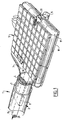
- the catheter 1 comprises in the usual manner a tube-like basic body 2 which extends from a proximal end, which remains outside the body of the patient when in use, to the distal end shown in figure 1.
- the basic body 2 comprises an outer tube-like element 3 with a central lumen inside of which an inner tube-like element 4 has been received, which is movable in a longitudinal direction.
- the inner tube-like element 4 is, as can be seen in figure 3, made up of a core 12 which has been formed by a helically coiled steel wire with a rectangular cross-section and is surrounded by a closely fitting outer sheath 11.
- a core 12 which has been formed by a helically coiled steel wire with a rectangular cross-section and is surrounded by a closely fitting outer sheath 11.
- a bar-like support 15 has been fixed inside the end of the inner tube-like element, for instance by means of cement 16.
- a plate-like carrier has been arranged on this support 15.
- a bag 19 has been mounted, which can be filled with a fluid via a channel 20 inside the support 15.
- the electrode array 5 has been arranged on top of the bag 19.
- the electrode array 5 is rectangular in shape and is made up of a great number of electrodes 6.
- the electrodes 6 have been made in the form of printed wiring on a foil substrate 7. As a result the electrode array 5 is pliable.
- conductors have been arranged in the form of printed wiring which are connected, each time, with electrodes 6 via metallized openings in the foil 7. From each electrode 6 one conductor runs along the back of the foil substrate 7 to a multiplexer 9, which has been mounted on a narrower end-section of this foil. The electrode array has been fixed with this narrower section in the end of the inner tube-like element 4.
- signal lines 10 extend to the proximal end of the catheter 1.
- the catheter 1 can be used to map electrical activity in the inner wall of the heart of a patient. Especially in the case of tachyarrhythmias this is desirable in order to map pathways of undesired electrical activity.
- the electrodes 6 of the electrode array 5 are manoeuvred against the wall of the heart. Because of the springy, compressible support of the bag 9 filled with fluid, the electrodes 6 can make proper contact with the surface of the wall.
- an ablation treatment can be carried out in order to disturb the undesired pathways.
- the electrodes 6, which are to ablate the wall of the heart against which they are positioned are activated by means of the multiplexer 9. In this way the undesired pathways can be interrupted very selectively and at exactly the right place.
- the electrode array 5 After the treatment, the electrode array 5 has to be folded again from the unfolded state illustrated in figure 1, in order to be able to remove it from the body of the patient.
- the carrier 18 of the electrode array 6 has been made of memory metal.
- the unfolded state of the carrier 18 illustrated in figure 1 that is to say the state in which it forms a more or less flat sheet, is the relatively relaxed state of the memory metal at raised temperature.
- the folded state to be described in greater detail below, is the relatively relaxed state at body temperature.
- heating means have been arranged on the carrier 18, which can be turned on via lines 21, 22 which extend to the proximal end.
- the carrier 18 is heated to above transition temperature, as a result of which the relatively relaxed unfolded state illustrated, is effected.
- the transition temperature can for instance be something like 45°C.
- the heating means are turned off.
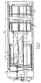
- the heating means have been arranged in two separate sections, that is to say separated in the longitudinal direction of the catheter.
- Figure 2 illustrates the state when the back section of the heating means, as seen in the figures, is turned off.
- the back section of the carrier 18 will cool down to body temperature and adopt the corresponding stable position, which corresponds to a form rolled up around the longitudinal axis.
- the fluid In order to move the carrier into the folded state, the fluid has been removed from the bag 19, so as to obtain a minimal thickness of the assembly.
- the second section of the heating means is turned off, as a result of which also the front section of the carrier 18, as seen in figures 1 and 2, will roll up in the direction of the arrow 24 and resume the folded state.
- the electrode array 5 can be pushed into the outer tube-like body 2 by pulling the inner tube-like body 4, in relation to the outer tube-like body 2, outwards at the proximal end.
- the electrode array 5 has been moved inwards over a distance 25 in the direction indicated by the arrow 23 of figure 2, so that it is enclosed completely by the outer tube-like body 3.
- the electrode array 5 is kept in the folded and retracted state, until the distal end of the catheter has reached the target position, in particular the heart of the patient. Then the electrode array will be extended and the heating means activated as a result of which the electrode array will unfold into the state illustrated in figure 1 and will be ready for use.
- the support 15 can be made in such a manner that it can be retracted separately in relation to the inner tube-like element 4.
- the support 15 will in that case be fixed to the carrier 18 only close to the latter's most distal section.
- the carrier comprises a pliable sheet such as a foil 33.
- the electrode array 34 has been arranged on this foil, for instance by means of a deposition technique.
- the sheet 33 is connected to wire like elements 35, 36.
- These wire like elements have been received in an inner tube-like element 32 of the basic body 31 and extend, via this tube-like element 32, to the proximal end of the catheter.
- a central wire like element 37 has been arranged as well, which supports the sheet 33 in the centre.
- the curve of the sheet 33 can be altered by rotating the wire like elements 35, 36 around their longitudinal axis.
- these wire like elements 35, 36 have been provided with operating means at their ends protruding from the proximal end of the basic body 31. These have not been illustrated here.
- the inner tube-like element 32 has been received in the basic body 31 in a movable manner, and by pulling at its proximal end the assembly of wire like elements 35, 36 bending outwards and the foil connected thereto, can be pulled into the basic body 31.
- the wire like elements 35, 36 are resilient so that they bend outwards automatically when extended and stretch the foil 33 by doing so.
- the catheter illustrated in figures 4 and 5 can also be further developed in a suitable manner so that the sheet 33 and the electrode array 34 arranged to it can curve around an axis at right angles to the longitudinal direction of the catheter.
- the central wire like element 37 will be made so that it can be moved separately in a way analogous to the one described when referring to figure 1.
- the sheet 33 will curve, so that the sheet 33 can curve in two directions around two axes at right angles to one another. Suitable manipulation of the elements 35, 36, 37 can consequently ensure proper contact between the electrode array 34 and for instance the wall of a heart.
- the catheter 40 also comprises a carrier in the form of a foil 43 on top of which the electrode array 44 has been arranged.
- the carrier 43 is connected with opposite sides to wire like elements 41, 42 which are elastic and push the opposite sides of the sheet apart in a resilient manner, so that, in the unfolded state shown in figure 6, the carrier 43 is kept stretched.
- the sheet 43 is also connected to a central pin 45 at a point in between the sides connected with the wire like elements 41, 42, which serves to support the sheet 43 and to fold the carrier in order to be able to retract it into the basic body 46.
- the operative end of the catheter 40 has been received inside the basic body 46 when inserting the catheter. As soon as the distal end of the catheter 40 has arrived at the position where the treatment is to be carried out, this operative end-section is extended by moving the inner tube-like element 47 in a longitudinal direction in relation to the outer tube-like element 46.
- the operative end has to be received once again inside the tube-like basic body 46.
- the central pin 45 is turned in the direction shown in figure 8, as a result of which the sheet 43 is wound around this pin and the wire like elements 41, 42 are pulled towards this pin 45.
- the assembly is gathered to form a small diameter and can be received in the basic body 46 by pulling the inner tube-like element 47 inwards.
- the carrier comprises an inflatable balloon 51.
- the latter may be preformed in a suitable manner to ensure that the electrode array 56 arranged on the wall thereof unfolds into a suitable shape as soon as the balloon is inflated.
- the electrode array 56 is connected to a multiplexer 57 via lines 55 arranged on the outside of the balloon, so that only one single line 58 has to be led to the proximal end of the catheter.
- a central pin 52 to the relatively proximal end of which the relatively proximal end of the balloon 51 has been arranged, extends through the basic body 59 of the catheter. After deflating the balloon 51, it can be pulled back inside the basic body 59, by moving the pin 52 in a longitudinal direction towards the proximal end.
- the state in which the balloon 51 has been received inside the basic body 59 has been illustrated in figure 10.
- figure 11 shows a possible cross-section of a catheter according to the invention whereby the carrier comprises a balloon 60.
- the balloon has been preformed in such a manner that it can have the elongated shape of the cross-section shown in the figure.
- an electrode array 65 has been arranged at a top surface , illustrated in figure 11, an electrode array 65 has been arranged.
- a partition 61 extends transversely through the balloon 60 as a result of which two compartments 62, 63 are formed.
- the compartments 62, 63 can be filled in different manners.
- the compartment 63 can for instance be inflated harder, forming a firm base, whereas the compartment 62 can be inflated relatively lightly as a result of which the support of the electrode array 65 is resilient and this electrode array 65 can adjust properly to the surface 66 to be treated.
- a central pin 64 has been drawn as well and serves for pulling the balloon into the basic body.
Description
- Figure 1
- shows a partly broken away perspective view of the distal end of a catheter according to an embodiment of the invention.
- Figure 2
- shows the distal end with the electrode array illustrated in figure 1 when being folded.
- Figure 3
- shows a partly broken away longitudinal cross-section of the catheter with the electrode array in the retracted state.
- Figure 4
- shows a partly broken away view of a catheter according to another embodiment of the invention.
- Figure 5
- shows a cross-section along the line V-V of figure 4.
- Figure 6
- shows yet another embodiment.
- Figure 7
- shows a cross-section along the line VII-VII of figure 7.
- Figure 8
- illustrates the way in which the carrier is wound up.
- Figure 9
- shows an embodiment of the invention whereby the carrier comprises an inflatable balloon.
- Figure 10
- shows the embodiment of figure 9 whereby the balloon has been retracted inside the basic body.
- Figure 11
- illustrates a cross-section through a carrier comprising a balloon.
Claims (18)
- Catheter (1) comprising a tube-like basic body (2) with a proximal end and a distal end, a connecting member arranged at the proximal end and an electrode array carried at the distal end, wherein the electrode array (5) is plate-like and has been arranged on a pliable carrier (18), which is movable between a folded state and an unfolded state transversely to the catheter, wherein folding means have been arranged for moving the carrier between the folded state and the unfolded state and furthermore comprising signal lines connected to the electrode array and extending to the proximal end, characterized in that the carrier comprises a sheet of memory metal having a transition temperature above body temperature, of which the folded state is a relatively relaxed state below the transition temperature and the unfolded state a relatively relaxed state at a temperature above the transition temperature and in that the carrier (18) is provided with heating means which are connected to a supply line (21, 22) extending to the proximal end, and are capable of heating the sheet to above the transition temperature.
- Catheter as claimed in claim 1, wherein the basic body comprises an outer tube-like body (3) with a central lumen, which has a bore which is at least marginally larger than the cross-section of the electrode array (5) in folded state and the carrier (18) is movable between a retracted position in folded state inside the central lumen and a position extended from there, and wherein retraction means have been arranged for the purpose of moving the carrier (18) between the retracted and the extended position.
- Catheter as claimed in claim 2, wherein the basic body (2) comprises an inner tube-like body movable inside the central lumen of the outer tube-like body (4) and the carrier (18) has been arranged at the distal end of the inner tube-like body (4).
- Catheter as claimed in claim 2, wherein the carrier is elastically deformable and is relatively relaxed in the unfolded state and wherein guiding means have been arranged at the distal end of the outer tube-like body (3) for the purpose of moving the carrier (18) from the unfolded into the folded state during the change from the extended into the retracted position.
- Catheter as claimed in one of the previous claims, wherein the electrode array (5) and the carrier (18) are rolled up around a longitudinal axis in the folded state.
- Catheter as claimed in one of the preceding claims, wherein the heating means are made up of at least two separate sections, separated transversely.
- Catheter as claimed in one of the previous claims, wherein a resilient, compressible cushion has been arranged in between the electrode array and the carrier.
- Catheter as claimed in claim 7, wherein the resilient, compressible cushion is a bag to be filled with a fluid.
- Catheter as claimed in claim 1, wherein the transition temperature of the memory metal is about 45'C.
- Catheter as claimed in claim 1, wherein the carrier comprises an inflatable balloon (51).
- Catheter as claimed in claim 10, wherein the balloon is connected with a distal end to an elongated body extending through the basic body in a movable manner, which can be used to pull the balloon into or extend it from the basic body.
- Catheter as claimed in claim 10 or 11, wherein the balloon comprises a partition (61) running parallel to a wall carrying the electrode array (65) and the compartments formed by this partition (61) can be supplied with fluid under pressure via separate lines (58) extending to the proximal end.
- Catheter as claimed in claim 12, wherein the compartment (63) turned away from the electrode array (65) is filled with a liquid.
- Catheter as claimed in one of the previous claims, wherein at least one multiplexer (9) has been received in the basic body (2) close to the distal end, which is connected with each of the electrodes (8) of the electrode array (18) on one side, and to the signal lines on the other side.
- Catheter as claimed in one of the previous claims, wherein the electrode array comprises a foil substrate (43), and connecting lines of the electrodes with the multiplexer have been made in the form of printed wiring on the foil substrate (43).
- Catheter as claimed in claim 15, wherein the electrodes have been formed as printed wiring on the foil substrate (43) on the other side from the connecting lines and the connecting lines are connected with the electrodes via metallized openings in the foil substrate.
- Catheter as claimed in one of the claims 14 - 16 inclusive, wherein the multiplexer (57) has been arranged on the foil substrate (43).
- Catheter as claimed in one of the previous claims, wherein the carrier is connected with a rigid support connected to the basic body in a fixed manner, extending in the longitudinal direction thereof.
Applications Claiming Priority (2)
| Application Number | Priority Date | Filing Date | Title |
|---|---|---|---|
| NL1001890 | 1995-12-13 | ||
| NL1001890A NL1001890C2 (en) | 1995-12-13 | 1995-12-13 | Catheter with plate-shaped electrode array. |
Publications (2)
| Publication Number | Publication Date |
|---|---|
| EP0779059A1 EP0779059A1 (en) | 1997-06-18 |
| EP0779059B1 true EP0779059B1 (en) | 2004-04-21 |
Family
ID=19762028
Family Applications (1)
| Application Number | Title | Priority Date | Filing Date |
|---|---|---|---|
| EP96203457A Expired - Lifetime EP0779059B1 (en) | 1995-12-13 | 1996-12-06 | Catheter with plate-like electrode array |
Country Status (5)
| Country | Link |
|---|---|
| US (1) | US5846196A (en) |
| EP (1) | EP0779059B1 (en) |
| CA (1) | CA2192012C (en) |
| DE (1) | DE69632238T2 (en) |
| NL (1) | NL1001890C2 (en) |
Cited By (13)
| Publication number | Priority date | Publication date | Assignee | Title |
|---|---|---|---|---|
| US8834461B2 (en) | 2005-07-11 | 2014-09-16 | Medtronic Ablation Frontiers Llc | Low power tissue ablation system |
| US8979841B2 (en) | 2005-06-20 | 2015-03-17 | Medtronic Ablation Frontiers Llc | Ablation catheter |
| US9005194B2 (en) | 2004-11-24 | 2015-04-14 | Medtronic Ablation Frontiers Llc | Atrial ablation catheter adapted for treatment of septal wall arrhythmogenic foci and method of use |
| US9474467B2 (en) | 2008-04-02 | 2016-10-25 | Rhythmia Medical, Inc. | Intracardiac tracking system |
| US9585588B2 (en) | 2014-06-03 | 2017-03-07 | Boston Scientific Scimed, Inc. | Electrode assembly having an atraumatic distal tip |
| US9687166B2 (en) | 2013-10-14 | 2017-06-27 | Boston Scientific Scimed, Inc. | High resolution cardiac mapping electrode array catheter |
| US9848795B2 (en) | 2014-06-04 | 2017-12-26 | Boston Scientific Scimed Inc. | Electrode assembly |
| US10034637B2 (en) | 2007-12-28 | 2018-07-31 | Boston Scientific Scimed, Inc. | Cardiac mapping catheter |
| US10758144B2 (en) | 2015-08-20 | 2020-09-01 | Boston Scientific Scimed Inc. | Flexible electrode for cardiac sensing and method for making |
| US10966623B2 (en) | 2015-06-29 | 2021-04-06 | Biosense Webster (Israel) Ltd. | Catheter having closed loop array with in-plane linear electrode portion |
| US11039772B2 (en) | 2015-06-29 | 2021-06-22 | Biosense Webster (Israel) Ltd. | Catheter with stacked spine electrode assembly |
| US11083400B2 (en) | 2014-11-20 | 2021-08-10 | Biosense Webster (Israel) Ltd. | Catheter with high density electrode spine array |
| US11116436B2 (en) | 2015-06-30 | 2021-09-14 | Biosense Webster (Israel) Ltd. | Catheter having closed electrode assembly with spines of uniform length |
Families Citing this family (177)
| Publication number | Priority date | Publication date | Assignee | Title |
|---|---|---|---|---|
| US6277112B1 (en) | 1996-07-16 | 2001-08-21 | Arthrocare Corporation | Methods for electrosurgical spine surgery |
| US5902272A (en) * | 1992-01-07 | 1999-05-11 | Arthrocare Corporation | Planar ablation probe and method for electrosurgical cutting and ablation |
| US6772012B2 (en) | 1995-06-07 | 2004-08-03 | Arthrocare Corporation | Methods for electrosurgical treatment of spinal tissue |
| US6482224B1 (en) | 1996-08-22 | 2002-11-19 | The Trustees Of Columbia University In The City Of New York | Endovascular flexible stapling device |
| US6540693B2 (en) * | 1998-03-03 | 2003-04-01 | Senorx, Inc. | Methods and apparatus for securing medical instruments to desired locations in a patients body |
| US6325800B1 (en) | 1998-04-15 | 2001-12-04 | Boston Scientific Corporation | Electro-cautery catheter |
| US6432104B1 (en) * | 1998-04-15 | 2002-08-13 | Scimed Life Systems, Inc. | Electro-cautery catherer |
| US6319241B1 (en) | 1998-04-30 | 2001-11-20 | Medtronic, Inc. | Techniques for positioning therapy delivery elements within a spinal cord or a brain |
| US6161047A (en) * | 1998-04-30 | 2000-12-12 | Medtronic Inc. | Apparatus and method for expanding a stimulation lead body in situ |
| US6606523B1 (en) * | 1999-04-14 | 2003-08-12 | Transneuronix Inc. | Gastric stimulator apparatus and method for installing |
| US20040215235A1 (en) | 1999-11-16 | 2004-10-28 | Barrx, Inc. | Methods and systems for determining physiologic characteristics for treatment of the esophagus |
| CA2388861C (en) | 1999-11-16 | 2013-09-03 | Robert A. Ganz | System and method of treating abnormal tissue in the human esophagus |
| US20060095032A1 (en) | 1999-11-16 | 2006-05-04 | Jerome Jackson | Methods and systems for determining physiologic characteristics for treatment of the esophagus |
| US7729756B2 (en) * | 2000-01-18 | 2010-06-01 | Siemens Aktiengesellschaft | Measurement system for examining a section of tissue on a patient and the use of a measurement system of this type |
| GB2405099B (en) * | 2000-05-30 | 2005-04-13 | Michael Peter Wildon | Cardiac stimulation apparatus |
| US7756584B2 (en) | 2000-07-13 | 2010-07-13 | Advanced Neuromodulation Systems, Inc. | Methods and apparatus for effectuating a lasting change in a neural-function of a patient |
| US7831305B2 (en) | 2001-10-15 | 2010-11-09 | Advanced Neuromodulation Systems, Inc. | Neural stimulation system and method responsive to collateral neural activity |
| US6928320B2 (en) | 2001-05-17 | 2005-08-09 | Medtronic, Inc. | Apparatus for blocking activation of tissue or conduction of action potentials while other tissue is being therapeutically activated |
| US6745079B2 (en) | 2001-11-07 | 2004-06-01 | Medtronic, Inc. | Electrical tissue stimulation apparatus and method |
| CA2474716A1 (en) | 2002-02-01 | 2003-08-07 | The Cleveland Clinic Foundation | Adjustable stimulation device and method of using same |
| US7740625B2 (en) * | 2002-04-24 | 2010-06-22 | Applied Medical Resources Corporation | Surgical digitizing apparatus and method |
| US7236830B2 (en) * | 2002-12-10 | 2007-06-26 | Northstar Neuroscience, Inc. | Systems and methods for enhancing or optimizing neural stimulation therapy for treating symptoms of Parkinson's disease and/or other movement disorders |
| US20050075680A1 (en) | 2003-04-18 | 2005-04-07 | Lowry David Warren | Methods and systems for intracranial neurostimulation and/or sensing |
| US6939348B2 (en) | 2003-03-27 | 2005-09-06 | Cierra, Inc. | Energy based devices and methods for treatment of patent foramen ovale |
| CA2519636A1 (en) | 2003-03-27 | 2004-10-14 | Cierra, Inc. | Methods and apparatus for treatment of patent foramen ovale |
| US7165552B2 (en) | 2003-03-27 | 2007-01-23 | Cierra, Inc. | Methods and apparatus for treatment of patent foramen ovale |
| US8021362B2 (en) | 2003-03-27 | 2011-09-20 | Terumo Kabushiki Kaisha | Methods and apparatus for closing a layered tissue defect |
| US7186251B2 (en) | 2003-03-27 | 2007-03-06 | Cierra, Inc. | Energy based devices and methods for treatment of patent foramen ovale |
| US7293562B2 (en) | 2003-03-27 | 2007-11-13 | Cierra, Inc. | Energy based devices and methods for treatment of anatomic tissue defects |
| US7972330B2 (en) | 2003-03-27 | 2011-07-05 | Terumo Kabushiki Kaisha | Methods and apparatus for closing a layered tissue defect |
| US7794456B2 (en) | 2003-05-13 | 2010-09-14 | Arthrocare Corporation | Systems and methods for electrosurgical intervertebral disc replacement |
| US7311701B2 (en) | 2003-06-10 | 2007-12-25 | Cierra, Inc. | Methods and apparatus for non-invasively treating atrial fibrillation using high intensity focused ultrasound |
| CA2534363A1 (en) | 2003-08-01 | 2005-02-10 | Brad Fowler | Apparatus and methods for applying neural stimulation to a patient |
| US7708733B2 (en) | 2003-10-20 | 2010-05-04 | Arthrocare Corporation | Electrosurgical method and apparatus for removing tissue within a bone body |
| US7212871B1 (en) * | 2003-12-24 | 2007-05-01 | Pacesetter, Inc. | Epicardial and myocardial leads for implanting in the heart by thoracotomy or port access surgeries with detachable electrode tip |
| US7150745B2 (en) * | 2004-01-09 | 2006-12-19 | Barrx Medical, Inc. | Devices and methods for treatment of luminal tissue |
| US20050203600A1 (en) * | 2004-03-12 | 2005-09-15 | Scimed Life Systems, Inc. | Collapsible/expandable tubular electrode leads |
| US7590454B2 (en) | 2004-03-12 | 2009-09-15 | Boston Scientific Neuromodulation Corporation | Modular stimulation lead network |
| US7367975B2 (en) | 2004-06-21 | 2008-05-06 | Cierra, Inc. | Energy based devices and methods for treatment of anatomic tissue defects |
| US7483747B2 (en) | 2004-07-15 | 2009-01-27 | Northstar Neuroscience, Inc. | Systems and methods for enhancing or affecting neural stimulation efficiency and/or efficacy |
| US20060089637A1 (en) | 2004-10-14 | 2006-04-27 | Werneth Randell L | Ablation catheter |
| US9101386B2 (en) | 2004-10-15 | 2015-08-11 | Amendia, Inc. | Devices and methods for treating tissue |
| EP1799129B1 (en) | 2004-10-15 | 2020-11-25 | Baxano, Inc. | Devices for tissue removal |
| US8062300B2 (en) | 2006-05-04 | 2011-11-22 | Baxano, Inc. | Tissue removal with at least partially flexible devices |
| US7938830B2 (en) | 2004-10-15 | 2011-05-10 | Baxano, Inc. | Powered tissue modification devices and methods |
| US8048080B2 (en) | 2004-10-15 | 2011-11-01 | Baxano, Inc. | Flexible tissue rasp |
| US8257356B2 (en) | 2004-10-15 | 2012-09-04 | Baxano, Inc. | Guidewire exchange systems to treat spinal stenosis |
| US8430881B2 (en) | 2004-10-15 | 2013-04-30 | Baxano, Inc. | Mechanical tissue modification devices and methods |
| US7578819B2 (en) | 2005-05-16 | 2009-08-25 | Baxano, Inc. | Spinal access and neural localization |
| US8221397B2 (en) | 2004-10-15 | 2012-07-17 | Baxano, Inc. | Devices and methods for tissue modification |
| US7553307B2 (en) | 2004-10-15 | 2009-06-30 | Baxano, Inc. | Devices and methods for tissue modification |
| US7738969B2 (en) | 2004-10-15 | 2010-06-15 | Baxano, Inc. | Devices and methods for selective surgical removal of tissue |
| US20110190772A1 (en) | 2004-10-15 | 2011-08-04 | Vahid Saadat | Powered tissue modification devices and methods |
| US9247952B2 (en) | 2004-10-15 | 2016-02-02 | Amendia, Inc. | Devices and methods for tissue access |
| US7887538B2 (en) | 2005-10-15 | 2011-02-15 | Baxano, Inc. | Methods and apparatus for tissue modification |
| US8617163B2 (en) | 2004-10-15 | 2013-12-31 | Baxano Surgical, Inc. | Methods, systems and devices for carpal tunnel release |
| US20100331883A1 (en) | 2004-10-15 | 2010-12-30 | Schmitz Gregory P | Access and tissue modification systems and methods |
| US20060106430A1 (en) * | 2004-11-12 | 2006-05-18 | Brad Fowler | Electrode configurations for reducing invasiveness and/or enhancing neural stimulation efficacy, and associated methods |
| US7429261B2 (en) * | 2004-11-24 | 2008-09-30 | Ablation Frontiers, Inc. | Atrial ablation catheter and method of use |
| US20060263338A1 (en) * | 2005-03-04 | 2006-11-23 | Jacoby Douglas B | Catheter-based delivery of Skeletal Myoblasts to the Myocardium of Damaged Hearts |
| US8109274B2 (en) | 2005-04-11 | 2012-02-07 | Terumo Kabushiki Kaisha | Methods and electrode apparatus to achieve a closure of a layered tissue defect |
| US20080051812A1 (en) * | 2006-08-01 | 2008-02-28 | Baxano, Inc. | Multi-Wire Tissue Cutter |
| US8062298B2 (en) | 2005-10-15 | 2011-11-22 | Baxano, Inc. | Flexible tissue removal devices and methods |
| US8092456B2 (en) | 2005-10-15 | 2012-01-10 | Baxano, Inc. | Multiple pathways for spinal nerve root decompression from a single access point |
| US20080086034A1 (en) | 2006-08-29 | 2008-04-10 | Baxano, Inc. | Tissue Access Guidewire System and Method |
| US8366712B2 (en) | 2005-10-15 | 2013-02-05 | Baxano, Inc. | Multiple pathways for spinal nerve root decompression from a single access point |
| US8702694B2 (en) | 2005-11-23 | 2014-04-22 | Covidien Lp | Auto-aligning ablating device and method of use |
| US7959627B2 (en) | 2005-11-23 | 2011-06-14 | Barrx Medical, Inc. | Precision ablating device |
| US7997278B2 (en) | 2005-11-23 | 2011-08-16 | Barrx Medical, Inc. | Precision ablating method |
| US7879034B2 (en) | 2006-03-02 | 2011-02-01 | Arthrocare Corporation | Internally located return electrode electrosurgical apparatus, system and method |
| GB0620061D0 (en) * | 2006-10-10 | 2006-11-22 | Medical Device Innovations Ltd | Oesophageal treatment apparatus and method |
| WO2008045877A2 (en) * | 2006-10-10 | 2008-04-17 | St. Jude Medical, Atrial Fibrillation Division, Inc. | Electrode tip and ablation system |
| US20080161893A1 (en) * | 2006-12-29 | 2008-07-03 | Saurav Paul | Fabric electrode head |
| WO2008092246A1 (en) * | 2007-01-29 | 2008-08-07 | Simon Fraser University | Transvascular nerve stimulation apparatus and methods |
| US7966076B2 (en) * | 2007-03-13 | 2011-06-21 | Cardiac Pacemakers, Inc. | Lead and apparatus for stimulation of the cardiac plexus |
| US8641711B2 (en) | 2007-05-04 | 2014-02-04 | Covidien Lp | Method and apparatus for gastrointestinal tract ablation for treatment of obesity |
| US8641704B2 (en) | 2007-05-11 | 2014-02-04 | Medtronic Ablation Frontiers Llc | Ablation therapy system and method for treating continuous atrial fibrillation |
| US10492729B2 (en) | 2007-05-23 | 2019-12-03 | St. Jude Medical, Cardiology Division, Inc. | Flexible high-density mapping catheter tips and flexible ablation catheter tips with onboard high-density mapping electrodes |
| US8784338B2 (en) | 2007-06-22 | 2014-07-22 | Covidien Lp | Electrical means to normalize ablational energy transmission to a luminal tissue surface of varying size |
| US8251992B2 (en) | 2007-07-06 | 2012-08-28 | Tyco Healthcare Group Lp | Method and apparatus for gastrointestinal tract ablation to achieve loss of persistent and/or recurrent excess body weight following a weight-loss operation |
| CN102688092B (en) | 2007-07-06 | 2015-04-22 | 柯惠有限合伙公司 | Ablation in the gastrointestinal tract to achieve hemostasis and eradicate lesions with a propensity for bleeding |
| US8273012B2 (en) | 2007-07-30 | 2012-09-25 | Tyco Healthcare Group, Lp | Cleaning device and methods |
| US8646460B2 (en) | 2007-07-30 | 2014-02-11 | Covidien Lp | Cleaning device and methods |
| EP2194861A1 (en) | 2007-09-06 | 2010-06-16 | Baxano, Inc. | Method, system and apparatus for neural localization |
| GB2453601B (en) * | 2007-10-12 | 2010-07-21 | Cardio Logic Innovations Ltd | Radio frequency catheter for the ablation of body tissues |
| US8192436B2 (en) | 2007-12-07 | 2012-06-05 | Baxano, Inc. | Tissue modification devices |
| US8540707B2 (en) * | 2007-12-21 | 2013-09-24 | St. Jude Medical, Atrial Fibrillation Division, Inc. | Template system and methods |
| US8326439B2 (en) | 2008-04-16 | 2012-12-04 | Nevro Corporation | Treatment devices with delivery-activated inflatable members, and associated systems and methods for treating the spinal cord and other tissues |
| US8398641B2 (en) | 2008-07-01 | 2013-03-19 | Baxano, Inc. | Tissue modification devices and methods |
| US9314253B2 (en) | 2008-07-01 | 2016-04-19 | Amendia, Inc. | Tissue modification devices and methods |
| US8409206B2 (en) | 2008-07-01 | 2013-04-02 | Baxano, Inc. | Tissue modification devices and methods |
| MX348805B (en) | 2008-07-14 | 2017-06-28 | Baxano Inc | Tissue modification devices. |
| US9119533B2 (en) * | 2008-10-07 | 2015-09-01 | Mc10, Inc. | Systems, methods, and devices having stretchable integrated circuitry for sensing and delivering therapy |
| US8389862B2 (en) | 2008-10-07 | 2013-03-05 | Mc10, Inc. | Extremely stretchable electronics |
| US9123614B2 (en) | 2008-10-07 | 2015-09-01 | Mc10, Inc. | Methods and applications of non-planar imaging arrays |
| EP2349440B1 (en) | 2008-10-07 | 2019-08-21 | Mc10, Inc. | Catheter balloon having stretchable integrated circuitry and sensor array |
| US8097926B2 (en) | 2008-10-07 | 2012-01-17 | Mc10, Inc. | Systems, methods, and devices having stretchable integrated circuitry for sensing and delivering therapy |
| US20100114283A1 (en) * | 2008-10-31 | 2010-05-06 | Medtronic, Inc. | Implantable medical lead |
| US9795442B2 (en) | 2008-11-11 | 2017-10-24 | Shifamed Holdings, Llc | Ablation catheters |
| CN104068933B (en) * | 2008-11-11 | 2017-03-15 | 施菲姆德控股有限责任公司 | The electrode assemblie of little profile |
| EP2404171A4 (en) * | 2009-03-03 | 2016-01-27 | Mc10 Inc | Systems, methods, and devices having stretchable integrated circuitry for sensing and delivering therapy |
| EP2405823A4 (en) | 2009-03-13 | 2012-07-04 | Baxano Inc | Flexible neural localization devices and methods |
| EP2805743A1 (en) * | 2009-04-03 | 2014-11-26 | Stryker Corporation | Delivery assembly for percutaneouly delivering and deploying an electrode array, the assembly including a core around which the array is wrapped |
| CN104548316B (en) | 2009-06-24 | 2018-01-26 | 施菲姆德控股有限责任公司 | Can steerable medical delivery devices and application method |
| US8394102B2 (en) | 2009-06-25 | 2013-03-12 | Baxano, Inc. | Surgical tools for treatment of spinal stenosis |
| WO2011119857A2 (en) | 2010-03-24 | 2011-09-29 | Shifamed, Llc | Intravascular tissue disruption |
| US9320868B2 (en) * | 2010-03-26 | 2016-04-26 | Flip Technologies Limited | Catheter and a method for manufacturing a catheter |
| US9655677B2 (en) | 2010-05-12 | 2017-05-23 | Shifamed Holdings, Llc | Ablation catheters including a balloon and electrodes |
| JP5792802B2 (en) | 2010-05-12 | 2015-10-14 | シファメド・ホールディングス・エルエルシー | Low profile electrode assembly |
| US8979838B2 (en) | 2010-05-24 | 2015-03-17 | Arthrocare Corporation | Symmetric switching electrode method and related system |
| EP2627243B1 (en) * | 2010-12-30 | 2020-01-22 | St. Jude Medical, Atrial Fibrillation Division, Inc. | System for diagnosing arrhythmias and directing catheter therapies |
| US8391947B2 (en) * | 2010-12-30 | 2013-03-05 | Biosense Webster (Israel), Ltd. | Catheter with sheet array of electrodes |
| US10278774B2 (en) | 2011-03-18 | 2019-05-07 | Covidien Lp | Selectively expandable operative element support structure and methods of use |
| AU2012246723C9 (en) | 2011-04-22 | 2014-08-28 | Topera, Inc. | Basket style cardiac mapping catheter having an atraumatic basket tip for detection of cardiac rhythm disorders |
| JP6527329B2 (en) | 2011-05-03 | 2019-06-05 | シファメド・ホールディングス・エルエルシー | Steerable delivery sheath |
| AU2012298709B2 (en) * | 2011-08-25 | 2015-04-16 | Covidien Lp | Systems, devices, and methods for treatment of luminal tissue |
| WO2013074036A1 (en) * | 2011-11-16 | 2013-05-23 | Cathprint Ab | Catheter component |
| US8961550B2 (en) | 2012-04-17 | 2015-02-24 | Indian Wells Medical, Inc. | Steerable endoluminal punch |
| US9226402B2 (en) | 2012-06-11 | 2015-12-29 | Mc10, Inc. | Strain isolation structures for stretchable electronics |
| US9295842B2 (en) | 2012-07-05 | 2016-03-29 | Mc10, Inc. | Catheter or guidewire device including flow sensing and use thereof |
| US9171794B2 (en) | 2012-10-09 | 2015-10-27 | Mc10, Inc. | Embedding thin chips in polymer |
| KR20150072415A (en) | 2012-10-09 | 2015-06-29 | 엠씨10, 인크 | Conformal electronics integrated with apparel |
| US20140110296A1 (en) | 2012-10-19 | 2014-04-24 | Medtronic Ardian Luxembourg S.A.R.L. | Packaging for Catheter Treatment Devices and Associated Devices, Systems, and Methods |
| US20140114215A1 (en) * | 2012-10-20 | 2014-04-24 | Medtronic Ardian Luxembourg S.A.R.L. | Methods for Renal Neuromodulation and Associated Systems and Devices |
| US20140200639A1 (en) * | 2013-01-16 | 2014-07-17 | Advanced Neuromodulation Systems, Inc. | Self-expanding neurostimulation leads having broad multi-electrode arrays |
| CN110141177B (en) | 2013-04-08 | 2021-11-23 | 阿帕玛医疗公司 | Ablation catheter |
| US10098694B2 (en) | 2013-04-08 | 2018-10-16 | Apama Medical, Inc. | Tissue ablation and monitoring thereof |
| US10349824B2 (en) | 2013-04-08 | 2019-07-16 | Apama Medical, Inc. | Tissue mapping and visualization systems |
| US9706647B2 (en) | 2013-05-14 | 2017-07-11 | Mc10, Inc. | Conformal electronics including nested serpentine interconnects |
| EP2818104B1 (en) * | 2013-06-25 | 2016-01-06 | VascoMed GmbH | Catheter and method for producing same |
| KR20160040670A (en) | 2013-08-05 | 2016-04-14 | 엠씨10, 인크 | Flexible temperature sensor including conformable electronics |
| CA2925387A1 (en) | 2013-10-07 | 2015-04-16 | Mc10, Inc. | Conformal sensor systems for sensing and analysis |
| US9763733B2 (en) | 2013-10-25 | 2017-09-19 | Covidien Lp | Unfurling electrode devices with the multiple longitudinal electrode segments |
| US9918789B2 (en) | 2013-10-25 | 2018-03-20 | Covidien Lp | Unfurling electrode devices with the protection element |
| CN105813545A (en) | 2013-11-22 | 2016-07-27 | Mc10股份有限公司 | Conformal sensor systems for sensing and analysis of cardiac activity |
| CN105813576B (en) * | 2013-11-26 | 2019-11-12 | 科菲戈公司 | Effect/reaction is superimposed the wide area tissue ablation device of dual cavity |
| US11096736B2 (en) * | 2013-12-09 | 2021-08-24 | Biosense Webster (Israel) Ltd. | Pericardial catheter with temperature sensing array |
| WO2015103580A2 (en) | 2014-01-06 | 2015-07-09 | Mc10, Inc. | Encapsulated conformal electronic systems and devices, and methods of making and using the same |
| JP6637896B2 (en) | 2014-03-04 | 2020-01-29 | エムシー10 インコーポレイテッドMc10,Inc. | Conformal IC device with flexible multi-part encapsulated housing for electronic devices |
| US10398488B2 (en) * | 2014-09-04 | 2019-09-03 | Medtronic Cryocath Lp | Cryoadhesive device for left atrial appendage occlusion |
| USD781270S1 (en) | 2014-10-15 | 2017-03-14 | Mc10, Inc. | Electronic device having antenna |
| US10368934B2 (en) | 2015-01-14 | 2019-08-06 | Covidien Lp | Arrangement of multi-channel bipolar electrode zones to minimize leakage and edge effects |
| WO2016123390A1 (en) * | 2015-01-28 | 2016-08-04 | St. Jude Medical, Cardiology Division, Inc. | Thermal mapping catheter |
| US10149716B2 (en) | 2015-02-02 | 2018-12-11 | Covidien Lp | Self-sizing catheter features to prevent over-tightening of the electrode |
| CN107530004A (en) | 2015-02-20 | 2018-01-02 | Mc10股份有限公司 | The automatic detection and construction of wearable device based on personal situation, position and/or orientation |
| US10398343B2 (en) | 2015-03-02 | 2019-09-03 | Mc10, Inc. | Perspiration sensor |
| EP3274037B1 (en) | 2015-03-27 | 2021-11-03 | Kalila Medical, Inc. | Steerable medical devices |
| JP6820864B2 (en) | 2015-04-24 | 2021-01-27 | カリラ メディカル インコーポレイテッド | Manipulable medical devices, systems and usage |
| US10653332B2 (en) | 2015-07-17 | 2020-05-19 | Mc10, Inc. | Conductive stiffener, method of making a conductive stiffener, and conductive adhesive and encapsulation layers |
| WO2017031129A1 (en) | 2015-08-19 | 2017-02-23 | Mc10, Inc. | Wearable heat flux devices and methods of use |
| CN108290070A (en) | 2015-10-01 | 2018-07-17 | Mc10股份有限公司 | Method and system for interacting with virtual environment |
| EP3359031A4 (en) | 2015-10-05 | 2019-05-22 | Mc10, Inc. | Method and system for neuromodulation and stimulation |
| AU2016343928B2 (en) * | 2015-10-30 | 2021-01-28 | Biosense Webster (Israel) Ltd. | Foldable 2-D CMUT-on-CMOS arrays |
| JP6866367B2 (en) | 2015-11-09 | 2021-04-28 | カリラ メディカル インコーポレイテッド | Steering assembly and usage of medical devices |
| WO2017087549A1 (en) | 2015-11-16 | 2017-05-26 | Apama Medical, Inc. | Energy delivery devices |
| EP3420732B8 (en) | 2016-02-22 | 2020-12-30 | Medidata Solutions, Inc. | System, devices, and method for on-body data and power transmission |
| EP3420733A4 (en) | 2016-02-22 | 2019-06-26 | Mc10, Inc. | System, device, and method for coupled hub and sensor node on-body acquisition of sensor information |
| CN109310340A (en) | 2016-04-19 | 2019-02-05 | Mc10股份有限公司 | For measuring the method and system of sweat |
| US10638976B2 (en) | 2016-04-28 | 2020-05-05 | Biosense Webster (Israel) Ltd | Method of constructing irrigated balloon catheter |
| US10660700B2 (en) * | 2016-04-28 | 2020-05-26 | Biosense Webster (Israel) Ltd. | Irrigated balloon catheter with flexible circuit electrode assembly |
| US20180014786A1 (en) | 2016-07-15 | 2018-01-18 | Dragon Medical Development Limited | Multi-spline, multi-electrode catheter and method of use for mapping of internal organs |
| US10447347B2 (en) | 2016-08-12 | 2019-10-15 | Mc10, Inc. | Wireless charger and high speed data off-loader |
| US11602630B2 (en) | 2017-06-07 | 2023-03-14 | Neuronexus Technologies, Inc. | Systems and methods for flexible electrode arrays |
| JP7050892B2 (en) | 2017-07-07 | 2022-04-08 | セント・ジュード・メディカル,カーディオロジー・ディヴィジョン,インコーポレイテッド | Layered high density electrode mapping catheter |
| KR102607016B1 (en) * | 2018-01-31 | 2023-11-29 | 삼성메디슨 주식회사 | Ultrasonic probe |
| US11642063B2 (en) | 2018-08-23 | 2023-05-09 | St. Jude Medical, Cardiology Division, Inc. | Curved high density electrode mapping catheter |
| US11246505B2 (en) | 2018-11-01 | 2022-02-15 | Biosense Webster (Israel) Ltd. | Using radiofrequency (RF) transmission system to find opening in tissue wall |
| USD968422S1 (en) | 2019-05-31 | 2022-11-01 | Biosense Webster (Israel) Ltd. | Display screen with transitional graphical user interface |
| USD968421S1 (en) | 2019-05-31 | 2022-11-01 | Biosense Webster (Israel) Ltd. | Display screen with a graphical user interface |
| USD969138S1 (en) | 2019-05-31 | 2022-11-08 | Biosense Webster (Israel) Ltd. | Display screen with a graphical user interface |
| US20210059745A1 (en) * | 2019-09-03 | 2021-03-04 | Biosense Webster (Israel) Ltd. | Mapping catheter with flex panel electrode assembly |
| US20210077183A1 (en) * | 2019-09-18 | 2021-03-18 | Biosense Webster (Israel) Ltd. | Catheter with thin-film electrodes on expandable mechanical structure |
| US11903639B2 (en) * | 2020-04-17 | 2024-02-20 | Biosense Webster (Israel) Ltd. | Flexible distal-end assembly with double-sided electrode array and irrigation |
| US20220047325A1 (en) | 2020-08-13 | 2022-02-17 | Biosense Webster (Israel) Ltd. | Balloon probe for irreversible electroporation |
| US11918281B2 (en) * | 2020-10-07 | 2024-03-05 | Biosense Webster (Israel) Ltd. | Folding fan catheter with electrodes |
| US20230190166A1 (en) * | 2021-12-21 | 2023-06-22 | CoreMap, Inc. | Devices and methods for tissue mapping |
| US20230200895A1 (en) * | 2021-12-27 | 2023-06-29 | Biosense Webster (Israel) Ltd. | Catheter end effector with resilient frame and flexible interior |
Family Cites Families (15)
| Publication number | Priority date | Publication date | Assignee | Title |
|---|---|---|---|---|
| US3326207A (en) * | 1964-07-10 | 1967-06-20 | James J Egan | Electrocardiac instrument for testing unborn infants |
| GB1424355A (en) * | 1972-03-11 | 1976-02-11 | Kent Cambridge Medical Ltd | Cardiac pacers |
| US3825015A (en) * | 1972-12-14 | 1974-07-23 | American Optical Corp | Single catheter for atrial and ventricular stimulation |
| US3995623A (en) * | 1974-12-23 | 1976-12-07 | American Hospital Supply Corporation | Multipurpose flow-directed catheter |
| US4172451A (en) * | 1978-04-06 | 1979-10-30 | Medical Evaluation Devices And Instruments Corp. | Intracardial electrode and a method of manufacture thereof |
| US4432369A (en) * | 1981-09-04 | 1984-02-21 | Medi-Tech, Incorporated | Electromagnetic sensor having three electrodes for measuring signals indicative of a biologic condition |
| US4425908A (en) * | 1981-10-22 | 1984-01-17 | Beth Israel Hospital | Blood clot filter |
| US4628937A (en) * | 1984-08-02 | 1986-12-16 | Cordis Corporation | Mapping electrode assembly |
| US4976711A (en) * | 1989-04-13 | 1990-12-11 | Everest Medical Corporation | Ablation catheter with selectively deployable electrodes |
| US5010895A (en) * | 1989-08-03 | 1991-04-30 | Empi, Inc. | Expandable vaginal electrode |
| US5255679A (en) * | 1992-06-02 | 1993-10-26 | Cardiac Pathways Corporation | Endocardial catheter for mapping and/or ablation with an expandable basket structure having means for providing selective reinforcement and pressure sensing mechanism for use therewith, and method |
| US5309910A (en) * | 1992-09-25 | 1994-05-10 | Ep Technologies, Inc. | Cardiac mapping and ablation systems |
| ATE176404T1 (en) * | 1992-09-30 | 1999-02-15 | Cardiac Pacemakers Inc | HINGED CUSHION ELECTRODE FOR CARDIAC REACH WITH A LADDER-FREE AREA THAT SERVES AS A HINGE |
| US5636634A (en) * | 1993-03-16 | 1997-06-10 | Ep Technologies, Inc. | Systems using guide sheaths for introducing, deploying, and stabilizing cardiac mapping and ablation probes |
| DE4418022A1 (en) * | 1994-05-19 | 1995-11-23 | Biotronik Mess & Therapieg | Electrode arrangement that can be used endoscopically |
-
1995
- 1995-12-13 NL NL1001890A patent/NL1001890C2/en not_active IP Right Cessation
-
1996
- 1996-12-04 CA CA002192012A patent/CA2192012C/en not_active Expired - Fee Related
- 1996-12-06 DE DE69632238T patent/DE69632238T2/en not_active Expired - Lifetime
- 1996-12-06 EP EP96203457A patent/EP0779059B1/en not_active Expired - Lifetime
- 1996-12-12 US US08/764,368 patent/US5846196A/en not_active Expired - Lifetime
Cited By (18)
| Publication number | Priority date | Publication date | Assignee | Title |
|---|---|---|---|---|
| US9005194B2 (en) | 2004-11-24 | 2015-04-14 | Medtronic Ablation Frontiers Llc | Atrial ablation catheter adapted for treatment of septal wall arrhythmogenic foci and method of use |
| US8979841B2 (en) | 2005-06-20 | 2015-03-17 | Medtronic Ablation Frontiers Llc | Ablation catheter |
| US9468495B2 (en) | 2005-06-20 | 2016-10-18 | Medtronic Ablation Frontiers Llc | Ablation catheter |
| US9566113B2 (en) | 2005-07-11 | 2017-02-14 | Medtronic Ablation Frontiers Llc | Low power tissue ablation system |
| US8834461B2 (en) | 2005-07-11 | 2014-09-16 | Medtronic Ablation Frontiers Llc | Low power tissue ablation system |
| US11272886B2 (en) | 2007-12-28 | 2022-03-15 | Boston Scientific Scimed, Inc. | Cardiac mapping catheter |
| US10034637B2 (en) | 2007-12-28 | 2018-07-31 | Boston Scientific Scimed, Inc. | Cardiac mapping catheter |
| US9474467B2 (en) | 2008-04-02 | 2016-10-25 | Rhythmia Medical, Inc. | Intracardiac tracking system |
| US9687166B2 (en) | 2013-10-14 | 2017-06-27 | Boston Scientific Scimed, Inc. | High resolution cardiac mapping electrode array catheter |
| US9585588B2 (en) | 2014-06-03 | 2017-03-07 | Boston Scientific Scimed, Inc. | Electrode assembly having an atraumatic distal tip |
| US9848795B2 (en) | 2014-06-04 | 2017-12-26 | Boston Scientific Scimed Inc. | Electrode assembly |
| US11083400B2 (en) | 2014-11-20 | 2021-08-10 | Biosense Webster (Israel) Ltd. | Catheter with high density electrode spine array |
| US10966623B2 (en) | 2015-06-29 | 2021-04-06 | Biosense Webster (Israel) Ltd. | Catheter having closed loop array with in-plane linear electrode portion |
| US11039772B2 (en) | 2015-06-29 | 2021-06-22 | Biosense Webster (Israel) Ltd. | Catheter with stacked spine electrode assembly |
| US11690552B2 (en) | 2015-06-29 | 2023-07-04 | Biosense Webster (Israel) Ltd. | Catheter with stacked spine electrode assembly |
| US11116436B2 (en) | 2015-06-30 | 2021-09-14 | Biosense Webster (Israel) Ltd. | Catheter having closed electrode assembly with spines of uniform length |
| US11723574B2 (en) | 2015-06-30 | 2023-08-15 | Biosense Webster (Israel) Ltd. | Catheter having closed electrode assembly with spines of uniform length |
| US10758144B2 (en) | 2015-08-20 | 2020-09-01 | Boston Scientific Scimed Inc. | Flexible electrode for cardiac sensing and method for making |
Also Published As
| Publication number | Publication date |
|---|---|
| CA2192012C (en) | 2005-11-22 |
| DE69632238T2 (en) | 2005-04-14 |
| DE69632238D1 (en) | 2004-05-27 |
| US5846196A (en) | 1998-12-08 |
| EP0779059A1 (en) | 1997-06-18 |
| NL1001890C2 (en) | 1997-06-17 |
| CA2192012A1 (en) | 1997-06-14 |
Similar Documents
| Publication | Publication Date | Title |
|---|---|---|
| EP0779059B1 (en) | Catheter with plate-like electrode array | |
| US5117828A (en) | Expandable esophageal catheter | |
| US5345936A (en) | Apparatus with basket assembly for endocardial mapping | |
| US5313943A (en) | Catheters and methods for performing cardiac diagnosis and treatment | |
| US20220192734A1 (en) | Fundus bumper mechanical reference for easier mechanism deployment | |
| US5471982A (en) | Cardiac mapping and ablation systems | |
| US7544166B2 (en) | Systems and methods for imaging with deployable imaging devices | |
| US5311866A (en) | Heart mapping catheter | |
| US5293869A (en) | Cardiac probe with dynamic support for maintaining constant surface contact during heart systole and diastole | |
| US5143067A (en) | Tool for implantable neural electrode | |
| US6163716A (en) | Cardiac mapping and ablation systems | |
| JP7046676B2 (en) | Balloon catheter with large area electrodes | |
| US5549108A (en) | Cardiac mapping and ablation systems | |
| US5680860A (en) | Mapping and/or ablation catheter with coilable distal extremity and method for using same | |
| US5327889A (en) | Mapping and ablation catheter with individually deployable arms and method | |
| US6632196B1 (en) | Dual balloon catheter and method of use | |
| EP1415680B1 (en) | Multi-tip steerable catheter | |
| US6205361B1 (en) | Implantable expandable multicontact electrodes | |
| US20030153905A1 (en) | Selective ablation system | |
| EP0499491A2 (en) | Endocardial mapping and ablation system and catheter probe and method | |
| JP7390374B2 (en) | Movable electrode for ablation volume by controlled irreversible electroporation | |
| WO1997017892A9 (en) | Endocardial mapping and/or ablation catheter probe and method | |
| JPH06142106A (en) | Intracardiac mapping utilizing catheter for abscission being separately controlled and apparatus and method for abscission | |
| JPH09504453A (en) | Endocardial mapping device and method | |
| JPH08504333A (en) | Electrode-supported splines for the cardiac system |
Legal Events
| Date | Code | Title | Description |
|---|---|---|---|
| PUAI | Public reference made under article 153(3) epc to a published international application that has entered the european phase |
Free format text: ORIGINAL CODE: 0009012 |
|
| AK | Designated contracting states |
Kind code of ref document: A1 Designated state(s): BE CH DE FR GB IE IT LI NL |
|
| 17P | Request for examination filed |
Effective date: 19971215 |
|
| 17Q | First examination report despatched |
Effective date: 20020118 |
|
| GRAH | Despatch of communication of intention to grant a patent |
Free format text: ORIGINAL CODE: EPIDOS IGRA |
|
| GRAS | Grant fee paid |
Free format text: ORIGINAL CODE: EPIDOSNIGR3 |
|
| GRAA | (expected) grant |
Free format text: ORIGINAL CODE: 0009210 |
|
| AK | Designated contracting states |
Kind code of ref document: B1 Designated state(s): BE CH DE FR GB IE IT LI NL |
|
| REG | Reference to a national code |
Ref country code: GB Ref legal event code: FG4D |
|
| RIC1 | Information provided on ipc code assigned before grant |
Ipc: 7A 61B 5/042 A |
|
| REG | Reference to a national code |
Ref country code: CH Ref legal event code: NV Representative=s name: ARNOLD & SIEDSMA AG Ref country code: CH Ref legal event code: EP |
|
| REG | Reference to a national code |
Ref country code: IE Ref legal event code: FG4D |
|
| REF | Corresponds to: |
Ref document number: 69632238 Country of ref document: DE Date of ref document: 20040527 Kind code of ref document: P |
|
| ET | Fr: translation filed | ||
| PLBE | No opposition filed within time limit |
Free format text: ORIGINAL CODE: 0009261 |
|
| STAA | Information on the status of an ep patent application or granted ep patent |
Free format text: STATUS: NO OPPOSITION FILED WITHIN TIME LIMIT |
|
| 26N | No opposition filed |
Effective date: 20050124 |
|
| PGFP | Annual fee paid to national office [announced via postgrant information from national office to epo] |
Ref country code: DE Payment date: 20131204 Year of fee payment: 18 Ref country code: CH Payment date: 20131212 Year of fee payment: 18 Ref country code: IE Payment date: 20131210 Year of fee payment: 18 Ref country code: GB Payment date: 20131204 Year of fee payment: 18 |
|
| PGFP | Annual fee paid to national office [announced via postgrant information from national office to epo] |
Ref country code: FR Payment date: 20131209 Year of fee payment: 18 Ref country code: IT Payment date: 20131220 Year of fee payment: 18 Ref country code: NL Payment date: 20131210 Year of fee payment: 18 |
|
| PGFP | Annual fee paid to national office [announced via postgrant information from national office to epo] |
Ref country code: BE Payment date: 20131217 Year of fee payment: 18 |
|
| PG25 | Lapsed in a contracting state [announced via postgrant information from national office to epo] |
Ref country code: BE Free format text: LAPSE BECAUSE OF NON-PAYMENT OF DUE FEES Effective date: 20141231 |
|
| REG | Reference to a national code |
Ref country code: DE Ref legal event code: R119 Ref document number: 69632238 Country of ref document: DE |
|
| REG | Reference to a national code |
Ref country code: NL Ref legal event code: V1 Effective date: 20150701 |
|
| REG | Reference to a national code |
Ref country code: NL Ref legal event code: V1 Effective date: 20150701 |
|
| REG | Reference to a national code |
Ref country code: CH Ref legal event code: PL |
|
| GBPC | Gb: european patent ceased through non-payment of renewal fee |
Effective date: 20141206 |
|
| REG | Reference to a national code |
Ref country code: IE Ref legal event code: MM4A |
|
| REG | Reference to a national code |
Ref country code: FR Ref legal event code: ST Effective date: 20150831 |
|
| PG25 | Lapsed in a contracting state [announced via postgrant information from national office to epo] |
Ref country code: NL Free format text: LAPSE BECAUSE OF NON-PAYMENT OF DUE FEES Effective date: 20150701 |
|
| PG25 | Lapsed in a contracting state [announced via postgrant information from national office to epo] |
Ref country code: CH Free format text: LAPSE BECAUSE OF NON-PAYMENT OF DUE FEES Effective date: 20141231 Ref country code: DE Free format text: LAPSE BECAUSE OF NON-PAYMENT OF DUE FEES Effective date: 20150701 Ref country code: IE Free format text: LAPSE BECAUSE OF NON-PAYMENT OF DUE FEES Effective date: 20141206 Ref country code: LI Free format text: LAPSE BECAUSE OF NON-PAYMENT OF DUE FEES Effective date: 20141231 Ref country code: GB Free format text: LAPSE BECAUSE OF NON-PAYMENT OF DUE FEES Effective date: 20141206 |
|
| PG25 | Lapsed in a contracting state [announced via postgrant information from national office to epo] |
Ref country code: FR Free format text: LAPSE BECAUSE OF NON-PAYMENT OF DUE FEES Effective date: 20141231 |
|
| PG25 | Lapsed in a contracting state [announced via postgrant information from national office to epo] |
Ref country code: IT Free format text: LAPSE BECAUSE OF NON-PAYMENT OF DUE FEES Effective date: 20141206 |