EP0779226A1 - Storage container for strip-shaped test elements - Google Patents
Storage container for strip-shaped test elements Download PDFInfo
- Publication number
- EP0779226A1 EP0779226A1 EP96120165A EP96120165A EP0779226A1 EP 0779226 A1 EP0779226 A1 EP 0779226A1 EP 96120165 A EP96120165 A EP 96120165A EP 96120165 A EP96120165 A EP 96120165A EP 0779226 A1 EP0779226 A1 EP 0779226A1
- Authority
- EP
- European Patent Office
- Prior art keywords
- storage container
- closure part
- container according
- quiver
- seal
- Prior art date
- Legal status (The legal status is an assumption and is not a legal conclusion. Google has not performed a legal analysis and makes no representation as to the accuracy of the status listed.)
- Granted
Links
Images


Classifications
-
- B—PERFORMING OPERATIONS; TRANSPORTING
- B65—CONVEYING; PACKING; STORING; HANDLING THIN OR FILAMENTARY MATERIAL
- B65D—CONTAINERS FOR STORAGE OR TRANSPORT OF ARTICLES OR MATERIALS, e.g. BAGS, BARRELS, BOTTLES, BOXES, CANS, CARTONS, CRATES, DRUMS, JARS, TANKS, HOPPERS, FORWARDING CONTAINERS; ACCESSORIES, CLOSURES, OR FITTINGS THEREFOR; PACKAGING ELEMENTS; PACKAGES
- B65D25/00—Details of other kinds or types of rigid or semi-rigid containers
- B65D25/20—External fittings
- B65D25/205—Means for the attachment of labels, cards, coupons or the like
-
- A—HUMAN NECESSITIES
- A61—MEDICAL OR VETERINARY SCIENCE; HYGIENE
- A61B—DIAGNOSIS; SURGERY; IDENTIFICATION
- A61B10/00—Other methods or instruments for diagnosis, e.g. instruments for taking a cell sample, for biopsy, for vaccination diagnosis; Sex determination; Ovulation-period determination; Throat striking implements
- A61B10/0096—Casings for storing test samples
-
- B—PERFORMING OPERATIONS; TRANSPORTING
- B65—CONVEYING; PACKING; STORING; HANDLING THIN OR FILAMENTARY MATERIAL
- B65D—CONTAINERS FOR STORAGE OR TRANSPORT OF ARTICLES OR MATERIALS, e.g. BAGS, BARRELS, BOTTLES, BOXES, CANS, CARTONS, CRATES, DRUMS, JARS, TANKS, HOPPERS, FORWARDING CONTAINERS; ACCESSORIES, CLOSURES, OR FITTINGS THEREFOR; PACKAGING ELEMENTS; PACKAGES
- B65D43/00—Lids or covers for rigid or semi-rigid containers
- B65D43/14—Non-removable lids or covers
- B65D43/16—Non-removable lids or covers hinged for upward or downward movement
- B65D43/162—Non-removable lids or covers hinged for upward or downward movement the container, the lid and the hinge being made of one piece
-
- B—PERFORMING OPERATIONS; TRANSPORTING
- B65—CONVEYING; PACKING; STORING; HANDLING THIN OR FILAMENTARY MATERIAL
- B65D—CONTAINERS FOR STORAGE OR TRANSPORT OF ARTICLES OR MATERIALS, e.g. BAGS, BARRELS, BOTTLES, BOXES, CANS, CARTONS, CRATES, DRUMS, JARS, TANKS, HOPPERS, FORWARDING CONTAINERS; ACCESSORIES, CLOSURES, OR FITTINGS THEREFOR; PACKAGING ELEMENTS; PACKAGES
- B65D53/00—Sealing or packing elements; Sealings formed by liquid or plastics material
-
- B—PERFORMING OPERATIONS; TRANSPORTING
- B65—CONVEYING; PACKING; STORING; HANDLING THIN OR FILAMENTARY MATERIAL
- B65D—CONTAINERS FOR STORAGE OR TRANSPORT OF ARTICLES OR MATERIALS, e.g. BAGS, BARRELS, BOTTLES, BOXES, CANS, CARTONS, CRATES, DRUMS, JARS, TANKS, HOPPERS, FORWARDING CONTAINERS; ACCESSORIES, CLOSURES, OR FITTINGS THEREFOR; PACKAGING ELEMENTS; PACKAGES
- B65D81/00—Containers, packaging elements, or packages, for contents presenting particular transport or storage problems, or adapted to be used for non-packaging purposes after removal of contents
- B65D81/24—Adaptations for preventing deterioration or decay of contents; Applications to the container or packaging material of food preservatives, fungicides, pesticides or animal repellants
- B65D81/26—Adaptations for preventing deterioration or decay of contents; Applications to the container or packaging material of food preservatives, fungicides, pesticides or animal repellants with provision for draining away, or absorbing, or removing by ventilation, fluids, e.g. exuded by contents; Applications of corrosion inhibitors or desiccators
- B65D81/266—Adaptations for preventing deterioration or decay of contents; Applications to the container or packaging material of food preservatives, fungicides, pesticides or animal repellants with provision for draining away, or absorbing, or removing by ventilation, fluids, e.g. exuded by contents; Applications of corrosion inhibitors or desiccators for absorbing gases, e.g. oxygen absorbers or desiccants
-
- G—PHYSICS
- G01—MEASURING; TESTING
- G01N—INVESTIGATING OR ANALYSING MATERIALS BY DETERMINING THEIR CHEMICAL OR PHYSICAL PROPERTIES
- G01N33/00—Investigating or analysing materials by specific methods not covered by groups G01N1/00 - G01N31/00
- G01N33/48—Biological material, e.g. blood, urine; Haemocytometers
- G01N33/483—Physical analysis of biological material
- G01N33/487—Physical analysis of biological material of liquid biological material
- G01N33/4875—Details of handling test elements, e.g. dispensing or storage, not specific to a particular test method
- G01N33/48778—Containers specially adapted therefor, e.g. for dry storage
-
- A—HUMAN NECESSITIES
- A61—MEDICAL OR VETERINARY SCIENCE; HYGIENE
- A61B—DIAGNOSIS; SURGERY; IDENTIFICATION
- A61B10/00—Other methods or instruments for diagnosis, e.g. instruments for taking a cell sample, for biopsy, for vaccination diagnosis; Sex determination; Ovulation-period determination; Throat striking implements
- A61B2010/0003—Other methods or instruments for diagnosis, e.g. instruments for taking a cell sample, for biopsy, for vaccination diagnosis; Sex determination; Ovulation-period determination; Throat striking implements including means for analysis by an unskilled person
- A61B2010/0006—Other methods or instruments for diagnosis, e.g. instruments for taking a cell sample, for biopsy, for vaccination diagnosis; Sex determination; Ovulation-period determination; Throat striking implements including means for analysis by an unskilled person involving a colour change
Definitions
- a number of containers are known in the prior art for storing test elements.
- a storage container in the form of a tube with a sealing plug which has a desiccant on the inside, is still widely used. While this form of packaging protects the test strips very effectively against moisture, mechanical stress and dirt, it has the disadvantage that the sealing plug is quite stiff if it is to seal sufficiently.
- the removal of test strips from the open tube is a process which is particularly difficult for hypoglycemic diabetics.
- the majority of the test strips sold commercially are used by this group of people.
- US Pat. No. 4,717,018 describes a storage container for test elements in which a push-in plug for closing the vessel opening is located directly on the vessel itself, so that the plug cannot be lost. In this embodiment too, a relatively large amount of force is required to open and close the sealing plug. Test strips are also removed by tilting the container and sliding the test strips through the opening. A user of this Storage container must ensure that the test strips do not fall off and become dirty when they are tipped out, which could make their intended use as diagnostic test means impossible.
- German laid-open specification DE 43 28 815 describes a system for storing test elements, in which the container is opened by means of a slide with which the vessel lid is pushed away. This system is easy to use and requires little effort. However, the storage container has a relatively complex mechanism, which entails corresponding manufacturing costs. This system is therefore especially designed as a refill package.
- the object of the present invention was to provide a storage container for strip-shaped test elements which is easy to use and requires little effort. It is also an object of the present invention to simplify the removal of test strips and to make them clearly identifiable to the user if the storage container is not completely closed. In addition, the new storage container should be easy to manufacture and inexpensive.
- a storage container for strip-shaped test elements which has a quiver which can be closed by a closure part connected to the quiver via a hinge, an elastic seal being located on the inside of the closure part, which opens when the storage container is closed rests on the edge of the quiver opening and is held in this closed position by a releasable holding device.
- the seal of the storage container In the closed position, the seal of the storage container is compressed and moves back into its uncompressed form after the holding device is released, so that the closure part is pivoted about the hinge axis and the storage container opens at least partially.
- the storage container is therefore open in the mechanical rest position.
- Test elements in the sense of the invention have a test zone on which a sample liquid, such as blood or urine, is applied.
- the sample produces a detectable change, such as discoloration, which can be used to determine the presence and / or concentration of an analyte in the sample.
- the test elements Because of the easier handling, the test elements usually have an elongated shape. Lots of the test elements on the market are sensitive to moisture, so that they must be kept closed in order to ensure the reliability of the analytical test carried out.
- the storage container according to the invention has a quiver in which the test elements are located.
- the quiver can have a square, rectangular or round cross section. An oval cross section of the quiver has proven to be advantageous in terms of handling.
- the quiver has an opening that is delimited by an edge. It has proven to be advantageous if this edge lies completely in one plane. Furthermore, it is advantageous if the opening is not within a lateral surface, but rather an entire end face of the quiver is opened, so that the edge surface of the quiver opening is oriented perpendicular to the longitudinal axis of the quiver.
- the length of the quiver depends on the length of the strip-shaped test elements. In practice, the length of the quiver will not be chosen to be significantly larger or smaller than the length of the test elements.
- Materials with sufficient rigidity can be used as the material for the quiver.
- plastics such as polyethylene, polypropylene and polystyrene are suitable.
- the storage container also has a closure part which is connected to the quiver via a hinge.
- the shape of the closure part is chosen so that it can close the opening of the quiver like a cap.
- the materials mentioned for the quiver are particularly suitable as the material for the closure part. It is particularly preferred if the case and the closure part are made of the same material, since the storage container can then be produced in one piece.
- the hinge that connects the closure part and the quiver can be, for example, a hinge for hinges or hinges. However, a film hinge is advantageously used, since in this case inexpensive injection molding is possible.
- an elastic seal is attached to the inside of the closure part, which is arranged so that it rests on the edge of the quiver or lies tightly against this edge when the storage container is closed.
- Foam rubber, styrene elastomers, polyolefin elastomers, polyamide elastomers, polyester elastomers and polyurethane elastomers are suitable as the material for the seal. Sealing rings made of the materials mentioned can, for example, be glued or welded into the inside of the closure part.
- the closure part is produced in a so-called hard / soft injection molding process. With this procedure first the hard closure part is injected and the soft rubber seal is injected.
- the container can also be sprayed onto the sealing rubber.
- This method also offers the advantage of a higher process reliability, since the assembly of the seal is carried out by the injection molding process, and thus separate manufacturing steps and also manual manufacturing steps can be avoided.
- the use of the overmolding process further reduces the manufacturing costs.
- Elastomers suitable according to the invention have a Shore hardness (DIN 53 505) of 30 to 80, preferably between 55 and 64.
- a particularly important aspect is the geometrical arrangement of the seal relative to the edge of the quiver opening. It has proven to be advantageous if the seal has an L-shaped cross section and is arranged such that a groove is formed between the closure part and the seal, the distance between which is given by the shorter segment of the L. With this arrangement, the edge of the quiver comes to lie in this groove when the storage container is closed and the seal presses against the quiver edge from the inside of the quiver. In order to achieve sufficient tightness, the width of the groove between the seal and the closure part is chosen so that it is smaller than the thickness of the quiver material. When closing, the edge of the quiver is therefore clamped in this groove, the seal being deformed.
- the storage container is in the closed state under a mechanical tension, which leads to an opening of the storage container when the holding device is unlocked.
- This effect can be supported by spring tension on the hinge.
- the storage container is visibly open if it is not locked by the holding device. This offers the advantage that an unlocked storage container is clearly visible. This can prevent the vessel from being completely closed is without this being recognized by the user.
- the storage container is preferably opened by 20 to 60 °.
- the mechanical rest position of the storage container according to the invention is in an open position. In this position, the closure part is pivoted about 30 ° relative to the closed position. In the closed position, the storage container is held by a holding device.
- the embodiments known in the prior art come into consideration for this holding device.
- the closure part has a pin or a lug on its inner lateral surface, which, in the closed position, engages in a recess in the outer lateral surface of the quiver.
- the holding device can be released manually by pressing on a position of the quiver adjacent to the depression or by pulling on the closure part. It is also possible to effect the holding device by deforming the storage container, for example by compressing it.
- the holding device consists of a recess or recess in the outer surface of the closure part, into which a pin, which is located on the outer outer surface of the quiver, engages.
- a pin which is located on the outer outer surface of the quiver.
- the holding device can be opened in a particularly easy-to-use manner by means of a slide which is attached to the storage container.
- the slide has guide elements which engage in corresponding guide elements on the storage container in such a way that the slide can be displaced in the direction of the longitudinal axis of the storage container.
- guide elements can be tongue and groove constructions, for example.
- a tongue on the closure part offers a further advantageous effect.
- the holding device is unlocked, the closure part is pivoted by the user by about 80 to 150 ° about the hinge axis and the entire device is tilted somewhat so that the test elements located in the holder slide out.
- the user In the case of devices known in the prior art (US Pat. No. 4,717,018), the user must ensure that the test strips do not fall out in an uncontrolled manner.
- the tongue on the closure part mentioned above can ensure that the test elements cannot slip out in an uncontrolled manner.
- the tongue of the closure part is at a distance from the opening of the quiver, which is essentially predetermined by the width of the closure part.
- the width of the closure part is advantageously chosen so that it is smaller than the length of the test elements, but large enough to ensure simple, manual removal. This is the case in practical cases when the width of the closure part is approximately in the range of 2 to 4 cm. If the storage container has the tongue mentioned on the closure part, the test elements slide against the tongue when the storage container is tilted, from where they can be removed manually in a simple manner. The tongue therefore acts as a baffle.
- the tongue is bent at the edges so that it adapts to the outer contour of the quiver when closed.
- the curvature of the tongue is also beneficial for the removal of test strips, since the curvature prevents them from accidentally slipping out of the side.
- the storage container can advantageously be sealed by a label which is stuck over the quiver and closure part.
- the label thus serves as a tamper-evident seal.
- Such a tamper-evident closure can be used particularly advantageously if the closure part has a tongue, the outside of which forms a continuous contour with the case.
- test elements In the field of clinical diagnostics, it is often necessary to label either the test elements or the storage container for test elements in terms of the production batch from which the test elements originate.
- a chamber that is accessible from the outside can be provided, but is separated from the interior of the storage container.
- a data carrier with corresponding information about the test carriers contained in the storage container can be stored in this chamber, which is advantageously slit-shaped. In this way, it is possible to reuse the storage container after emptying, since only the data carrier has to be replaced when new test elements are filled. An exchange of the desiccant is normally also necessary to ensure that the test elements are properly stored.
- Test elements commonly used in the prior art are generally sensitive to moisture.
- the storage container according to the invention offers good protection against the ingress of moisture in the closed state, it is advantageous to provide a desiccant inside the storage container, since moist ambient air penetrates each time the storage container is opened.
- a desiccant inside the storage container ensures that the test elements can function properly for longer.
- the desiccant can advantageously be introduced into the bottom of the quiver, where it is separated from the test strips by a moisture-permeable membrane (for example cardboard).
- Suitable desiccants are well known in the art. For example, silica gel, molecular sieves, etc. are suitable.
- the invention also includes a method for making test elements available, in which a storage container filled with test elements is opened by loosening the holding device, then the closure part is pivoted about the hinge axis and the storage container is tilted such that the test elements slide against the closure part.
- the test elements can be removed manually from here. After removal, the storage container is closed by the user by pivoting the closure part and engaging the holding device.
- the invention also includes a method for producing a device according to the invention, in which the quiver, closure part and hinge are injection-molded in one piece and the seal on the inside of the closure part is added by a hard / soft injection molding method (overmolding method).
- FIG. 1 shows an external view of a storage container for strip-shaped test elements according to the invention.
- the storage container (1) has a quiver (2) and a closure part (3) which are connected to one another via a film hinge (5).
- the closure part (3) has a tongue (4) which, when the storage container is closed, lies against the outer surface of the quiver (2).
- the storage container shown in Fig. 1 was made in one piece by injection molding from polypropylene.
- Fig. 2 shows the storage container (1) in front view. It can be seen that the cross section of the storage container is oval, which has proven to be favorable for handling.
- a recess (6) can also be seen in the quiver, which serves to allow the user to open the storage container. To open, the user can either press on the recess (6) and thus unlock the holding device or, thanks to the recess (6), he can press under the edge of the tongue (4) and thus effect an unlocking.
- FIG. 3 shows a cross section through a storage container according to the invention along the line 3-3 shown in FIG. 2.
- Fig. 3 shows how the closure part (3) and the edge of the quiver opening interlock. This can be seen in more detail from the enlarged detail in FIG. 3A.
- the closure part (3) has an outer edge (20) which has an outer surface of the closure part.
- An annular peripheral edge (21) is attached to the inside of the closure part (3).
- the edges (20) and (21) form a circumferential groove. In this groove there is a seal (22) made of a styrene elastomer. When the storage container is closed, the edge of the quiver compresses the seal (22).
- FIG. 3B shows a further possible embodiment of the holding device.
- the tongue (4) of the closure part there is a recess (15) which is latched onto a pin (16).
- the recess (6) in the quiver adjoins the pin (16), so that when the recess (6) is pressed, the pin (16) moves away from the recess (15) and the holding device is opened. Due to the mechanical tension in the compressed seal (22), the closure part (3) rotates about the axis predetermined by the film hinge (5) and the closure part (3) springs open.
- a desiccant chamber (10) can also be seen, which is located in the bottom of the storage container.
- the desiccant chamber is separated from the rest of the interior of the storage container by a cardboard cover plate (11) which is permeable to moisture, so that the test elements cannot come into direct contact with the desiccant.
- a slot-shaped chamber in the storage container can be seen in FIG. 3, which is accessible from the underside of the storage container.
- a data carrier (13) which can be removed manually from the chamber.
- Information about the test elements e.g. B. batch-specific data, in the form of a bar code or a chip.
- Fig. 4 shows two open positions of the storage container.
- the closure part In the open position X, the closure part is open about 30 ° with respect to the fully closed position. The closure part jumps into this position when the holding device is unlocked.
- the opening position Y corresponds to a position in which the closure part is brought by the user to remove test elements. In this position, the closure part is opened approximately 110 ° with respect to the closed position.
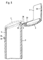
- FIG. 5 shows a modified embodiment of the storage container according to the invention. This embodiment differs from that described above in terms of sealing against moisture ingress.
- the closure part of this embodiment is in two parts.
- the first part corresponds to the first embodiment and has an outer edge (20) and a tongue (4).
- the seal is provided by a circumferential annular bead (23) with an L-shaped cross section.
- the ring bead (23) is attached so that there is a circumferential groove together with the outer edge (20).
- the width of this groove is given by the smaller segment of the L-shaped ring bead.
- the longer subsegment of the annular bead (23) forms an inner edge which is analogous to the inner edge (21) of the first-mentioned embodiment.
- Fig. 5 the storage container is shown both in the open position and closed. The open position corresponds to the state in which the storage container is removed from the injection mold.
- FIG. 5 it can also be seen how the annular bead (23) is deformed in the closed position by the edge of the quiver opening. The edge of the quiver opening clamps between the outer edge (20) and the ring bead (23) and presses the ring bead inwards. As in the aforementioned embodiment, the deformation of the elastic annular bead causes a mechanical tension, which causes the storage container to open as soon as the holding device is unlocked.
- the holding device of the embodiment shown in Fig. 5 consists of a recess (30) in the tongue (4) on the closure part and a pin (31) which is located on the outer peripheral surface of the quiver (2).
- elastomers are applied to the right and / or left above the hinge (5), which are compressed when the storage container is closed. It has proven to be advantageous to apply several upstanding pegs of elastomers.
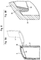
- FIG. 6 A further embodiment of the storage container according to the invention is shown in FIG. 6.
- the upper region of the storage container can be seen in FIG. 6A.
- this embodiment corresponds to that shown in FIG. 5.
- Figures 6A and 6B show a further possibility of sealing.
- On the inside of the closure part (3) there is an annular peripheral edge (32) which is made in one piece with the closure part (3).
- a sealing edge (33) is injected, which in its shape in essentially corresponds to the inner edge (21) of the closure part (Fig. 3A).
- the storage container is shown open and closed. In the closed position, the sealing edge (33) is deformed by the edge of the quiver and is therefore under mechanical tension. After releasing the holding device, the reservoir opens due to this mechanical tension.
- FIG. 7A shows an embodiment of the storage container with a slide (40) for opening the closure part (3).
- the opening process is carried out by moving the slide in the direction shown by the arrow.
- FIG. 7B shows in more detail a favorable design of the slide (40) with a bevelled edge (41). The interaction of this bevel with the closure part (3) can be seen more clearly from FIG. 7C.
- the slide is located partially below the closure part and is pushed like a wedge between the closure part and the quiver (2) of the storage container during displacement.
Abstract
Description
Die Erfindung betrifft Vorratsbehältnisse für streifenförmige Testelemente mit
- einem Köcher, der eine Öffnung besitzt, die durch einen Rand begrenzt ist,
- einem Verschlußteil, das über ein Scharnier mit dem Köcher verbunden ist und das an seiner Innenseite eine elastische Dichtung besitzt, die bei geschlossenem Vorratsbehältnis dichtend an dem Rand des Köchers anliegt, und
- eine lösbare Haltevorrichtung, die das Vorratsbehältnis in geschlossener Position hält,
wobei die Dichtung bei geschlossenem Vorratsbehältnis deformiert ist und sich beim Lösen der Haltevorrichtung in ihre nicht deformierte Form (Ruhelage) zurückbewegt, wobei das Verschlußteil um die Achse des Scharniers verschwenkt wird und sich das Vorratsbehältnis zumindest teilweise öffnet.
- a quiver that has an opening that is delimited by an edge,
- a closure part which is connected to the quiver via a hinge and which has on its inside an elastic seal which, when the storage container is closed, lies sealingly against the edge of the quiver, and
- a releasable holding device which holds the storage container in the closed position,
the seal being deformed when the storage container is closed and moving back into its undeformed shape (rest position) when the holding device is released, the closure part being pivoted about the axis of the hinge and the storage container opening at least partially.
Im Stand der Technik sind für die Bevorratung von Testelementen eine Reihe von Behältnissen bekannt. Trotz einer relativ schlechten Handhabbarkeit wird ein Vorratsbehältnis in Form einer Röhre mit einem Dichtungsstopfen, der an seiner Innenseite ein Trockenmittel besitzt, noch vielfach eingesetzt. Während diese Verpackungsform die Teststreifen sehr effektiv vor Feuchtigkeit, mechanischer Beanspruchung und Verschmutzung schützt, besitzt sie den Nachteil, daß der Verschlußstopfen recht schwergängig ist, wenn er genügend dichten soll. Weiterhin ist die Entnahme von Teststreifen aus der geöffneten Röhre ein Prozeß, der insbesondere unterzuckerten Diabetikern Schwierigkeiten bereitet. Der größte Teil der im Handel vertriebenen Teststreifen wird jedoch von diesem Personenkreis verwendet.A number of containers are known in the prior art for storing test elements. Despite a relatively poor manageability, a storage container in the form of a tube with a sealing plug, which has a desiccant on the inside, is still widely used. While this form of packaging protects the test strips very effectively against moisture, mechanical stress and dirt, it has the disadvantage that the sealing plug is quite stiff if it is to seal sufficiently. Furthermore, the removal of test strips from the open tube is a process which is particularly difficult for hypoglycemic diabetics. However, the majority of the test strips sold commercially are used by this group of people.
In der US-Patentanmeldung US-4,717,018 wird ein Vorratsbehältnis für Testelemente beschrieben, bei dem sich ein Eindrückstopfen zum Verschluß der Gefäßöffnung direkt am Gefäß selbst befindet, so daß der Stopfen nicht verlorengehen kann. Auch bei dieser Ausführungsform ist ein relativ großer Kraftaufwand zum Öffnen und Schließen des Verschlußstopfens notwendig. Weiterhin erfolgt die Entnahme von Teststreifen, indem das Behältnis gekippt wird und die Teststreifen durch die Öffnung rutschen. Ein Benutzer dieses Vorratsbehältnisses muß dafür Sorge tragen, daß die Teststreifen beim Herauskippen nicht herunterfallen und verschmutzt werden, was ihre bestimmungsgemäße Verwendung als diagnostisches Testmittel unmöglich machen könnte.US Pat. No. 4,717,018 describes a storage container for test elements in which a push-in plug for closing the vessel opening is located directly on the vessel itself, so that the plug cannot be lost. In this embodiment too, a relatively large amount of force is required to open and close the sealing plug. Test strips are also removed by tilting the container and sliding the test strips through the opening. A user of this Storage container must ensure that the test strips do not fall off and become dirty when they are tipped out, which could make their intended use as diagnostic test means impossible.
In der deutschen Offenlegungsschrift DE 43 28 815 ist ein System zur Bevorratung von Testelementen beschrieben, bei dem die Öffnung des Behältnisses über einen Schieber erfolgt, mit dem der Gefäßdeckel weggeschoben wird. Dieses System ist einfach und mit geringem Kraftaufwand zu bedienen. Das Vorratsbehältnis besitzt jedoch eine verhältnismäßig aufwendige Mechanik, die entsprechende Fertigungskosten nach sich zieht. Daher ist dieses System insbesondere als Nachfüllverpackung konzipiert.The German laid-open specification DE 43 28 815 describes a system for storing test elements, in which the container is opened by means of a slide with which the vessel lid is pushed away. This system is easy to use and requires little effort. However, the storage container has a relatively complex mechanism, which entails corresponding manufacturing costs. This system is therefore especially designed as a refill package.
Aufgabe der vorliegenden Erfindung war es, ein Vorratsbehältnis für streifenförmige Testelemente zur Verfügung zu stellen, das einfach und mit geringem Kraftaufwand zu bedienen ist. Außerdem ist es eine Aufgabe der vorliegenden Erfindung, die Entnahme von Teststreifen zu vereinfachen und für den Benutzer eindeutig kenntlich zu machen, wenn das Vorratsbehältnis nicht vollständig geschlossen ist. Obendrein soll das neuartige Vorratsbehältnis einfach herstellbar und kostengünstig sein.The object of the present invention was to provide a storage container for strip-shaped test elements which is easy to use and requires little effort. It is also an object of the present invention to simplify the removal of test strips and to make them clearly identifiable to the user if the storage container is not completely closed. In addition, the new storage container should be easy to manufacture and inexpensive.
Die vorgenannten Aufgaben wurden erfindungsgemäß durch ein Vorratsbehältnis für streifenförmige Testelemente gelöst, das einen Köcher besitzt, der durch ein über ein Scharnier mit dem Köcher verbundenes Verschlußteil verschlossen werden kann, wobei sich an der Innenseite des Verschlußteils eine elastische Dichtung befindet, die bei geschlossenem Vorratsbehältnis auf dem Rand der Köcheröffnung aufliegt und in dieser geschlossenen Position durch eine lösbare Haltevorrichtung gehalten wird. In der geschlossenen Position ist die Dichtung des Vorratsbehältnisses komprimiert und bewegt sich nach dem Lösen der Haltevorrichtung in ihre unkomprimierte Form zurück, so daß das Verschlußteil um die Scharnierachse verschwenkt wird und sich das Vorratsbehaltnis zumindest teilweise öffnet. Erfindungsgemäß ist es wichtig, daß die Öffnung des Vorratsbehältnisses nach Lösen der Haltevorrichtung von selbst, d. h. ohne ein weiteres Zutun des Benutzers, erfolgt. In der mechanischen Ruhelage ist das Vorratsbehaltnis daher geöffnet.The above-mentioned objects were achieved according to the invention by a storage container for strip-shaped test elements, which has a quiver which can be closed by a closure part connected to the quiver via a hinge, an elastic seal being located on the inside of the closure part, which opens when the storage container is closed rests on the edge of the quiver opening and is held in this closed position by a releasable holding device. In the closed position, the seal of the storage container is compressed and moves back into its uncompressed form after the holding device is released, so that the closure part is pivoted about the hinge axis and the storage container opens at least partially. According to the invention, it is important that the opening of the storage container by itself after loosening the holding device, i. H. without any further action on the part of the user. The storage container is therefore open in the mechanical rest position.
Testelemente im Sinne der Erfindung besitzen eine Testzone, auf der eine Probenflüssigkeit, wie beispielsweise Blut oder Harn, aufgegeben wird. Die Probe erzeugt eine detektierbare Veränderung, wie beispielsweise eine Verfärbung, anhand derer die Anwesenheit und/oder Konzentration eines Analyten in der Probe ermittelt werden kann. Aufgrund der einfacheren Handhabbarkeit besitzen die Testelemente in der Regel eine langgestreckte Gestalt. Viele der im Handel befindlichen Testelemente sind gegen Feuchtigkeit empfindlich, so daß sie verschlossen aufbewahrt werden müssen, um die Verläßlichkeit des durchgeführten analytischen Tests zu gewährleisten.Test elements in the sense of the invention have a test zone on which a sample liquid, such as blood or urine, is applied. The sample produces a detectable change, such as discoloration, which can be used to determine the presence and / or concentration of an analyte in the sample. Because of the easier handling, the test elements usually have an elongated shape. Lots of the test elements on the market are sensitive to moisture, so that they must be kept closed in order to ensure the reliability of the analytical test carried out.
Das erfindungsgemäße Vorratsbehältnis besitzt einen Köcher, in dem sich die Testelemente befinden. Der Köcher kann einen quadratischen, rechteckigen oder runden Querschnitt besitzen. Als vorteilhaft in der Handhabbarkeit hat sich ein ovaler Querschnitt des Köchers erwiesen. Der Köcher besitzt eine Öffnung, die durch einen Rand begrenzt ist. Es hat sich als vorteilhaft herausgestellt, wenn dieser Rand vollständig in einer Ebene liegt. Weiterhin ist es günstig, wenn die Öffnung nicht innerhalb einer Mantelfläche liegt, sondern eine gesamte Stirnseite des Köchers geöffnet ist, so daß die Randfläche der Köcheröffnung senkrecht zur Längsachse des Köchers ausgerichtet ist. Die Länge des Köchers richtet sich nach der Länge der streifenförmigen Testelemente. In der Praxis wird man die Länge des Köchers nicht wesentlich größer oder kleiner wählen als die Länge der Testelemente.The storage container according to the invention has a quiver in which the test elements are located. The quiver can have a square, rectangular or round cross section. An oval cross section of the quiver has proven to be advantageous in terms of handling. The quiver has an opening that is delimited by an edge. It has proven to be advantageous if this edge lies completely in one plane. Furthermore, it is advantageous if the opening is not within a lateral surface, but rather an entire end face of the quiver is opened, so that the edge surface of the quiver opening is oriented perpendicular to the longitudinal axis of the quiver. The length of the quiver depends on the length of the strip-shaped test elements. In practice, the length of the quiver will not be chosen to be significantly larger or smaller than the length of the test elements.
Als Material für den Köcher kommen Materialien mit einer ausreichenden Steifigkeit in Betracht. Insbesondere sind Kunststoffe wie Polyethylen, Polypropylen und Polystyrol geeignet.Materials with sufficient rigidity can be used as the material for the quiver. In particular, plastics such as polyethylene, polypropylene and polystyrene are suitable.
Das Vorratsbehältnis besitzt weiterhin ein Verschlußteil, das über ein Scharnier mit dem Köcher verbunden ist. Die Form des Verschlußteiles ist so gewählt, daß sie wie eine Kappe die Öffnung des Köchers verschließen kann. Als Material für das Verschlußteil kommen insbesondere die für den Köcher genannten Materialien in Frage. Besonders bevorzugt ist es, wenn Köcher und Verschlußteil aus dem gleichen Material bestehen, da das Vorratsbehältnis dann einteilig hergestellt werden kann. Das Scharnier, das Verschlußteil und Köcher verbindet, kann beispielsweise ein Band- oder Gelenkscharnier sein. Vorteilhaft wird jedoch ein Filmscharnier verwendet, da in diesem Fall eine kostengünstige Herstellung im Spritzgußverfahren möglich ist. Ein wesentliches Merkmal der vorliegenden Erfindung ist es, daß an der Innenseite des Verschlußteiles eine elastische Dichtung angebracht ist, die so angeordnet ist, daß sie bei geschlossenem Vorratsbehältnis dichtend auf dem Rand des Köchers auf- oder an diesem Rand anliegt. Als Material für die Dichtung kommen Moosgummi, Styrolelastomere, Polyolefinelastomere, Polyamidelastomere, Polyesterelastomere und Polyurethanelastomere in Frage. Dichtringe aus den genannten Materialien können in die Innenseite des Verschlußteiles beispielsweise hineingeklebt oder hineingeschweißt sein. Bei einer besonders bevorzugten Ausführungsform der Erfindung wird der Verschlußteil in einem sogenannten Hart-/Weich-Spritzgießverfahren hergestellt. Bei diesem Verfahren wird zunächst der harte Verschlußteil gespritzt und das weiche Dichtungsgummi aufgespritzt. Umgekehrt ist auch ein Aufspritzen des Behälters auf das Dichtungsgummi möglich. Dieses Verfahren bietet auch den Vorteil einer höheren Prozeßsicherheit, da die Montage der Dichtung durch das Spritzgußverfahren vorgenommen wird und damit separate Herstellungsschritte und auch manuelle Fertigungsschritte vermieden werden können. Der Einsatz des Overmoulding-Verfahrens vermindert weiterhin die Herstellkosten.The storage container also has a closure part which is connected to the quiver via a hinge. The shape of the closure part is chosen so that it can close the opening of the quiver like a cap. The materials mentioned for the quiver are particularly suitable as the material for the closure part. It is particularly preferred if the case and the closure part are made of the same material, since the storage container can then be produced in one piece. The hinge that connects the closure part and the quiver can be, for example, a hinge for hinges or hinges. However, a film hinge is advantageously used, since in this case inexpensive injection molding is possible. An important feature of the present invention is that an elastic seal is attached to the inside of the closure part, which is arranged so that it rests on the edge of the quiver or lies tightly against this edge when the storage container is closed. Foam rubber, styrene elastomers, polyolefin elastomers, polyamide elastomers, polyester elastomers and polyurethane elastomers are suitable as the material for the seal. Sealing rings made of the materials mentioned can, for example, be glued or welded into the inside of the closure part. In a particularly preferred embodiment of the invention, the closure part is produced in a so-called hard / soft injection molding process. With this procedure first the hard closure part is injected and the soft rubber seal is injected. Conversely, the container can also be sprayed onto the sealing rubber. This method also offers the advantage of a higher process reliability, since the assembly of the seal is carried out by the injection molding process, and thus separate manufacturing steps and also manual manufacturing steps can be avoided. The use of the overmolding process further reduces the manufacturing costs.
Eine besonders geeignete Kombination ergibt sich bei diesem Verfahren, wenn für den Verschlußteil Polypropylen oder Polyamid eingesetzt wird und als elastisches Dichtmaterial Styrolelastomere oder Polyolefinelastomere gewählt werden. Erfindungsgemäß geeignete Elastomere besitzen eine Shore-Härte (DIN 53 505) von 30 bis 80, vorzugsweise zwischen 55 und 64.A particularly suitable combination results in this process if polypropylene or polyamide is used for the closure part and styrene elastomers or polyolefin elastomers are selected as the elastic sealing material. Elastomers suitable according to the invention have a Shore hardness (DIN 53 505) of 30 to 80, preferably between 55 and 64.
Ein besonders wichtiger Aspekt ist die geometrische Anordnung der Dichtung relativ zum Rand der Köcheröffnung. Es hat sich als vorteilhaft herausgestellt, wenn die Dichtung in ihrem Querschnitt L-förmig ausgebildet ist und so angeordnet wird, daß zwischen Verschlußteil und Dichtung eine Nut entsteht, deren Abstand durch das kürzere Segment des L gegeben ist. Bei dieser Anordnung kommt der Rand des Köchers bei geschlossenem Vorratsbehältnis in dieser Nut zu liegen und die Dichtung drückt von der Innenseite des Köchers gegen den Köcherrand. Um eine ausreichende Dichtigkeit zu erzielen, wird die Breite der Nut zwischen Dichtung und Verschlußteil so gewählt, daß sie kleiner ist als die Dicke des Köchermaterials. Bei einem Verschließen wird daher der Köcherrand in diese Nut eingeklemmt, wobei die Dichtung deformiert wird. Aufgrund dieser Deformation steht das Vorratsbehältnis in geschlossenem Zustand unter einer mechanischen Spannung, die zu einer Öffnung des Vorratsbehältnisses führt, wenn die Haltevorrichtung entriegelt wird. Dieser Effekt kann durch eine Federspannung des Scharniers noch unterstützt werden. Es ist weiterhin möglich, zusätzlich zur beschriebenen Dichtung elastische Materialien im Bereich des Scharniers anzubringen, die bei verschlossenem Vorratsbehältnis komprimiert sind.A particularly important aspect is the geometrical arrangement of the seal relative to the edge of the quiver opening. It has proven to be advantageous if the seal has an L-shaped cross section and is arranged such that a groove is formed between the closure part and the seal, the distance between which is given by the shorter segment of the L. With this arrangement, the edge of the quiver comes to lie in this groove when the storage container is closed and the seal presses against the quiver edge from the inside of the quiver. In order to achieve sufficient tightness, the width of the groove between the seal and the closure part is chosen so that it is smaller than the thickness of the quiver material. When closing, the edge of the quiver is therefore clamped in this groove, the seal being deformed. Because of this deformation, the storage container is in the closed state under a mechanical tension, which leads to an opening of the storage container when the holding device is unlocked. This effect can be supported by spring tension on the hinge. In addition to the seal described, it is also possible to apply elastic materials in the area of the hinge which are compressed when the storage container is closed.
Während es bei Vorratsbehaltnissen des Standes der Technik (z. B. DE 43 28 815) beabsichtigt ist, die Ruheposition des Vorratsbehältnisses so zu wählen, daß das Behältnis geschlossen ist, wurde bei der vorliegenden Erfindung ein entgegengesetzter Weg eingeschlagen. Das Vorratsbehältnis steht sichtbar offen, wenn es nicht durch die Haltevorrichtung verriegelt ist. Dies bietet den Vorteil, daß ein unverschlossenes Vorratsbehältnis deutlich sichtbar offensteht. Damit kann verhindert werden, daß das Gefäß nicht vollständig verschlossen ist, ohne daß dies vom Benutzer erkannt werden kann. Vorzugsweise ist das Vorratsbehältnis in der Ruhelage um 20 bis 60 ° geöffnet.While it is intended in prior art storage containers (e.g. DE 43 28 815) to choose the rest position of the storage container so that the container is closed, an opposite path has been taken in the present invention. The storage container is visibly open if it is not locked by the holding device. This offers the advantage that an unlocked storage container is clearly visible. This can prevent the vessel from being completely closed is without this being recognized by the user. In the rest position, the storage container is preferably opened by 20 to 60 °.
Neben der bereits beschriebenen Ausführungsform, bei der sich der Rand des Köchers in einer Nut befindet, die auf einer Seite von der Dichtung begrenzt wird, ist auch eine Ausführungsform möglich, bei der die Dichtung auf den Rand des Köchers drückt. Diese Ausführungsform ist zwar scheinbar einfacher, stellt jedoch an die mechanische Abstimmung von Köcheröffnung und Dichtung höhere Anforderungen.In addition to the embodiment already described, in which the edge of the quiver is located in a groove which is delimited on one side by the seal, an embodiment is also possible in which the seal presses on the edge of the quiver. Although this embodiment is apparently simpler, it places higher demands on the mechanical coordination of the quiver opening and the seal.
Wie bereits ausgeführt, befindet sich die mechanische Ruhelage des erfindungsgemäßen Vorratsbehältnisses in einer geöffneten Stellung. In dieser Position ist das Verschlußteil etwa um 30 ° gegenüber der geschlossenen Position verschwenkt. In der geschlossenen Position wird das Vorratsbehältnis durch eine Haltevorrichtung gehalten. Für diese Haltevorrichtung kommen die im Stand der Technik bekannten Ausführungsformen in Betracht. Insbesondere hat es sich als vorteilhaft erwiesen, wenn das Verschlußteil an seiner inneren Mantelfläche einen Zapfen oder eine Nase besitzt, die in geschlossener Stellung in eine Vertiefung in der äußeren Mantelfläche des Köchers einrastet. Durch Drücken auf eine der Vertiefung benachbarte Stelle des Köchers oder durch ein Ziehen an dem Verschlußteil kann die Haltevorrichtung manuell gelöst werden. Es ist weiterhin auch möglich, die Haltevorrichtung durch eine Deformation des Vorratsbehältnisses, beispielsweise ein Zusammendrücken, zu bewirken. Bei einer weiteren Ausführungsform besteht die Haltevorrichtung aus einer Vertiefung oder Ausnehmung in der Mantelfläche des Verschlußteiles, in die einen Zapfen, der sich auf der äußeren Mantelfläche des Köchers befindet, eingreift. Die Möglichkeiten zur Lösung der Haltevorrichtung entsprechen denen der vorgenannten Ausführungsform. Für beide exemplarisch genannten Haltevorrichtungen ist es vorteilhaft, wenn der Verschlußteil eine Lasche oder Zunge besitzt, die bei geschlossenem Vorratsbehältnis auf der Mantelfläche des Köchers zu liegen kommt. Die verschlußteilseitigen Elemente der Haltevorrichtung können vorteilhaft in den Bereich dieser Zunge verlegt werden.As already stated, the mechanical rest position of the storage container according to the invention is in an open position. In this position, the closure part is pivoted about 30 ° relative to the closed position. In the closed position, the storage container is held by a holding device. The embodiments known in the prior art come into consideration for this holding device. In particular, it has proven to be advantageous if the closure part has a pin or a lug on its inner lateral surface, which, in the closed position, engages in a recess in the outer lateral surface of the quiver. The holding device can be released manually by pressing on a position of the quiver adjacent to the depression or by pulling on the closure part. It is also possible to effect the holding device by deforming the storage container, for example by compressing it. In a further embodiment, the holding device consists of a recess or recess in the outer surface of the closure part, into which a pin, which is located on the outer outer surface of the quiver, engages. The possibilities for solving the holding device correspond to those of the aforementioned embodiment. For both holding devices mentioned by way of example, it is advantageous if the closure part has a tab or tongue which comes to rest on the outer surface of the quiver when the storage container is closed. The fastener part-side elements of the holding device can advantageously be moved into the area of this tongue.
Die Haltevorrichtung kann besonders handhabungsfreundlich durch einen Schieber geöffnet werden, der an dem Vorratsbehältnis angebracht ist. Der Schieber besitzt Führungselemente, die in entsprechende Führungselemente an dem Vorratsbehältnis so eingreifen, daß eine Verschiebung des Schiebers in Richtung der Längsachse des Vorratsbehältnisses möglich ist. Derartige Führungselemente können beispielsweise Nut- und Federkonstruktionen sein. Bei geschlossenem Vorratsbehältnis befindet sich der Schieber in einer ersten Position, in der sich eine Kante des Schiebers an dem Verschlußteil bzw. der Zunge befindet oder zumindest in der Nähe dieser Teile angeordnet ist. Durch Verschieben des Schiebers in Richtung auf das Verschlußteil wird die Haltevorrichtung entriegelt. Besonders vorteilhaft ist die Kante des Schiebers angeschrägt und der mit dieser Kante in Anlage kommende Bereich des Verschlußteils ebenfalls. Beim Verschieben des Schiebers drängt sich die Kante des Schiebers unter das Verschlußteil bzw. unter die Zunge und bewirkt so eine Entriegelung der Haltevorrichtung. Nach dem Verschieben des Schiebers befindet sich dieser in einer zweiten Position, aus der er durch manuelles Verschieben zurück in die erste Position bewegt werden kann. Bei Verwendung einer abgeschrägten Kante des Schiebers kann diese Zurückbewegung jedoch auch einfach durch Zudrücken des Verschlußteils erfolgen.The holding device can be opened in a particularly easy-to-use manner by means of a slide which is attached to the storage container. The slide has guide elements which engage in corresponding guide elements on the storage container in such a way that the slide can be displaced in the direction of the longitudinal axis of the storage container. Such guide elements can be tongue and groove constructions, for example. When the storage container is closed, the slide is in a first position in which an edge of the slide is located on the closure part or the tongue or at least in the vicinity of these parts. The holding device is unlocked by moving the slide in the direction of the closure part. The edge of the slide is beveled particularly advantageously, and the region of the closure part which comes into contact with this edge is likewise chamfered. When the slide is moved, the edge of the slide pushes under the closure part or under the tongue and thus unlocks the holding device. After moving the slider, it is in a second position from which it can be moved back to the first position by manually moving it. When using a bevelled edge of the slider, however, this backward movement can also be carried out simply by pressing the closure part shut.
Die Verwendung einer Zunge an dem Verschlußteil bietet einen weiteren vorteilhaften Effekt. Zum Öffnen des Vorratsbehältnisses wird die Haltevorrichtung entriegelt, das Verschlußteil vom Benutzer um etwa 80 bis 150 ° um die Scharnierachse geschwenkt und die gesamte Vorrichtung etwas gekippt, so daß die im Köcher befindlichen Testelemente herausrutschen. Bei im Stand der Technik bekannten Vorrichtungen (US-4,717,018) muß der Anwender selbst dafür Sorge tragen, daß die Teststreifen nicht unkontrolliert herausfallen. Durch die vorstehend genannte Zunge an dem Verschlußteil kann jedoch sichergestellt werden, daß die Testelemente nicht unkontrolliert herausrutschen können. Wenn das Verschlußteil durch Verschwenken um ca. 80 bis 190 °, vorzugsweise 90 ° geöffnet wurde, befindet sich die Zunge des Verschlußteiles zur Öffnung des Köchers in einem Abstand, der im wesentlichen durch die Breite des Verschlußteiles vorgegeben ist. Vorteilhaft wird die Breite des Verschlußteiles so gewählt, daß sie kleiner ist als die Länge der Testelemente, jedoch groß genug, um eine einfache, manuelle Entnahme zu gewährleisten. Dies ist in praktischen Fällen dann der Fall, wenn die Breite des Verschlußteiles etwa im Bereich von 2 bis 4 cm liegt. Besitzt das Vorratsbehältnis die genannte Zunge an dem Verschlußteil, so rutschen die Testelemente bei Verkippen des Vorratsbehältnisses gegen die Zunge, von wo sie auf einfache Weise manuell entnommen werden können. Die Zunge übernimmt daher die Funktion einer Prallplatte. Weiterhin ist es günstig, wenn die Zunge an den Rändern gebogen ist, so daß sie sich in geschlossenem Zustand der Außenkontur des Köchers anpaßt. Die Krümmung der Zunge ist auch günstig für die Entnahme von Teststreifen, da diese durch die Krümmung an einem unbeabsichtigten seitlichen Herausrutschen gehindert werden.The use of a tongue on the closure part offers a further advantageous effect. To open the storage container, the holding device is unlocked, the closure part is pivoted by the user by about 80 to 150 ° about the hinge axis and the entire device is tilted somewhat so that the test elements located in the holder slide out. In the case of devices known in the prior art (US Pat. No. 4,717,018), the user must ensure that the test strips do not fall out in an uncontrolled manner. However, the tongue on the closure part mentioned above can ensure that the test elements cannot slip out in an uncontrolled manner. If the closure part has been opened by pivoting by approximately 80 to 190 °, preferably 90 °, the tongue of the closure part is at a distance from the opening of the quiver, which is essentially predetermined by the width of the closure part. The width of the closure part is advantageously chosen so that it is smaller than the length of the test elements, but large enough to ensure simple, manual removal. This is the case in practical cases when the width of the closure part is approximately in the range of 2 to 4 cm. If the storage container has the tongue mentioned on the closure part, the test elements slide against the tongue when the storage container is tilted, from where they can be removed manually in a simple manner. The tongue therefore acts as a baffle. Furthermore, it is advantageous if the tongue is bent at the edges so that it adapts to the outer contour of the quiver when closed. The curvature of the tongue is also beneficial for the removal of test strips, since the curvature prevents them from accidentally slipping out of the side.
Vorteilhaft kann das Vorratsbehältnis, durch ein Etikett, das über Köcher und Verschlußteil geklebt wird, versiegelt werden. Das Etikett dient somit als Originalitätsverschluß. Besonders vorteilhaft ist ein solcher Originalitätsverschluß einsetzbar, wenn das Verschlußteil eine Zunge besitzt, deren Außenseite mit dem Köcher eine durchgehende Kontur bildet.The storage container can advantageously be sealed by a label which is stuck over the quiver and closure part. The label thus serves as a tamper-evident seal. Such a tamper-evident closure can be used particularly advantageously if the closure part has a tongue, the outside of which forms a continuous contour with the case.
Im Bereich der klinischen Diagnostik ist es häufig notwendig, entweder die Testelemente oder das Vorratsbehältnis für Testelemente dahingehend zu kennzeichnen, aus welcher Herstellungscharge die Testelemente stammen. Bei dem erfindungsgemäßen Vorratsbehältnis kann eine von der Außenseite zugängliche Kammer vorgesehen werden, die jedoch gegenüber dem Innenraum des Vorratsbehältnisses abgetrennt ist. In diese Kammer, die vorteilhaft schlitzförmig ausgebildet wird, kann ein Datenträger mit entsprechenden Informationen über die im Vorratsbehältnis enthaltenen Testträger aufbewahrt werden. Auf diese Weise ist es möglich, das Vorratsbehältnis nach Entleerung einer nochmaligen Verwendung zuzuführen, da beim Einfüllen neuer Testelemente lediglich der Datenträger ausgewechselt werden muß. Zur einwandfreien Bevorratung der Testelemente ist normalerweise auch ein Austausch des Trockenmittels notwendig.In the field of clinical diagnostics, it is often necessary to label either the test elements or the storage container for test elements in terms of the production batch from which the test elements originate. In the storage container according to the invention, a chamber that is accessible from the outside can be provided, but is separated from the interior of the storage container. A data carrier with corresponding information about the test carriers contained in the storage container can be stored in this chamber, which is advantageously slit-shaped. In this way, it is possible to reuse the storage container after emptying, since only the data carrier has to be replaced when new test elements are filled. An exchange of the desiccant is normally also necessary to ensure that the test elements are properly stored.
Im Stand der Technik gebräuchliche Testelemente sind in der Regel empfindlich gegen Feuchtigkeit. Obwohl das erfindungsgemäße Vorratsbehältnis in verschlossenem Zustand einen guten Schutz gegen eindringende Feuchte bietet, ist es vorteilhaft, im Inneren des Vorratsbehältnisses ein Trockenmittel vorzusehen, da bei jedem Öffnen des Vorratsbehältnisses feuchte Umgebungsluft eindringt. Durch ein Trockenmittel im Inneren des Vorratsbehältnisses kann für die Testelemente eine längere einwandfreie Funktion gewährleistet werden. Vorteilhaft kann das Trockenmittel in den Boden des Köchers eingebracht werden, wo es durch eine feuchtigkeitsdurchlässige Membran (beispielsweise Karton) gegenüber den Teststreifen abgetrennt wird. Geeignete Trockenmittel sind im Stand der Technik hinlänglich bekannt. Geeignet sind beispielsweise Kieselgel, Molekularsiebe usw.Test elements commonly used in the prior art are generally sensitive to moisture. Although the storage container according to the invention offers good protection against the ingress of moisture in the closed state, it is advantageous to provide a desiccant inside the storage container, since moist ambient air penetrates each time the storage container is opened. A desiccant inside the storage container ensures that the test elements can function properly for longer. The desiccant can advantageously be introduced into the bottom of the quiver, where it is separated from the test strips by a moisture-permeable membrane (for example cardboard). Suitable desiccants are well known in the art. For example, silica gel, molecular sieves, etc. are suitable.
Zur Erfindung gehört weiterhin ein Verfahren zum Zurverfügungsstellen von Testelementen, bei dem ein mit Testelementen gefülltes Vorratsbehältnis durch Lösen der Haltevorrichtung geöffnet, darauf der Verschlußteil um die Scharnierachse verschwenkt und das Vorratsbehältnis so gekippt wird, daß die Testelemente gegen das Verschlußteil rutschen. Von hier können die Testelemente manuell entnommen werden. Nach der Entnahme wird das Vorratsbehältnis vom Benutzer durch Verschwenken des Verschlußteiles und Einrasten der Haltevorrichtung verschlossen.The invention also includes a method for making test elements available, in which a storage container filled with test elements is opened by loosening the holding device, then the closure part is pivoted about the hinge axis and the storage container is tilted such that the test elements slide against the closure part. The test elements can be removed manually from here. After removal, the storage container is closed by the user by pivoting the closure part and engaging the holding device.
Weiterhin gehört zur Erfindung ein Verfahren zur Herstellung einer erfindungsgemäßen Vorrichtung, bei dem Köcher, Verschlußteil und Scharnier einteilig gespritzt werden und die Dichtung an der Innenseite des Verschlußteiles durch ein Hart-/Weich-Spritzgußverfahren hinzugefügt wird (Overmoulding-Verfahren).The invention also includes a method for producing a device according to the invention, in which the quiver, closure part and hinge are injection-molded in one piece and the seal on the inside of the closure part is added by a hard / soft injection molding method (overmolding method).
Die vorliegende Erfindung wird anhand der folgenden Figuren näher erläutert:
- Fig. 1:
- Außenansicht des Vorratsbehältnisses von der Seite
- Fig. 2:
- Außenansicht des Vorratsbehältnisses von der Frontseite
- Fig. 3:
- Querschnitt durch das Vorratsbehältnis entlang der Linie 3-3 in Fig. 2
- Fig. 4:
- Querschnitt durch das Vorratsbehältnis mit zwei Öffnungsstellungen des Verschlußteiles
- Fig. 5:
- Querschnitt einer zweiten Ausführungsform des Vorratsbehältnisses mit geöffnetem und geschlossenem Verschlußteil
- Fig. 1:
- External view of the storage container from the side
- Fig. 2:
- External view of the storage container from the front
- Fig. 3:
- Cross section through the storage container along the line 3-3 in FIG. 2
- Fig. 4:
- Cross section through the storage container with two open positions of the closure part
- Fig. 5:
- Cross section of a second embodiment of the storage container with open and closed closure part
Fig. 1 zeigt eine Außenansicht eines erfindungsgemäßen Vorratsbehältnisses für streifenförmige Testelemente. Das Vorratsbehältnis (1) besitzt einen Köcher (2) und ein Verschlußteil (3), die über ein Filmscharnier (5) miteinander verbunden sind. Der Verschlußteil (3) besitzt eine Zunge (4), die bei geschlossenem Vorratsbehältnis an der äußeren Mantelfläche des Köchers (2) anliegt. Das in Fig. 1 dargestellte Vorratsbehältnis wurde einteilig im Spritzgußverfahren aus Polypropylen hergestellt.1 shows an external view of a storage container for strip-shaped test elements according to the invention. The storage container (1) has a quiver (2) and a closure part (3) which are connected to one another via a film hinge (5). The closure part (3) has a tongue (4) which, when the storage container is closed, lies against the outer surface of the quiver (2). The storage container shown in Fig. 1 was made in one piece by injection molding from polypropylene.
Fig. 2 zeigt das Vorratsbehältnis (1) in Frontansicht. Es ist zu erkennen, daß der Querschnitt des Vorratsbehältnisses oval ist, was sich als günstig für die Handhabung erwiesen hat. In Fig. 2 ist weiterhin eine Vertiefung (6) im Köcher zu erkennen, die dazu dient, dem Benutzer eine Öffnung des Vorratsbehältnisses zu ermöglichen. Zum Öffnen kann der Benutzer entweder auf die Vertiefung (6) drücken und so die Haltevorrichtung entriegeln oder er kann dank der Vertiefung (6) unter den Rand der Zunge (4) drücken und so eine Entriegelung bewirken.Fig. 2 shows the storage container (1) in front view. It can be seen that the cross section of the storage container is oval, which has proven to be favorable for handling. In Fig. 2, a recess (6) can also be seen in the quiver, which serves to allow the user to open the storage container. To open, the user can either press on the recess (6) and thus unlock the holding device or, thanks to the recess (6), he can press under the edge of the tongue (4) and thus effect an unlocking.
Fig. 3 zeigt einen Querschnitt durch ein erfindungsgemäßes Vorratsbehältnis entlang der in Fig. 2 eingezeichneten Linie 3-3. Fig. 3 zeigt, wie das Verschlußteil (3) und der Rand der Köcheröffnung ineinandergreifen. Detaillierter ist dies aus der Ausschnittsvergrößerung in Fig. 3A zu erkennen. Das Verschlußteil (3) besitzt eine äußere Kante (20), die eine Mantelfläche des Verschlußteiles bildet. Auf der Innenseite des Verschlußteiles (3) ist eine ringförmig umlaufende Kante (21) angebracht. Die Kanten (20) und (21) bilden eine umlaufende Nut. In dieser Nut befindet sich eine Dichtung (22) aus einem Styrolelastomeren. Bei geschlossenem Vorratsbehältnis drückt der Köcherrand die Dichtung (22) zusammen.FIG. 3 shows a cross section through a storage container according to the invention along the line 3-3 shown in FIG. 2. Fig. 3 shows how the closure part (3) and the edge of the quiver opening interlock. This can be seen in more detail from the enlarged detail in FIG. 3A. The closure part (3) has an outer edge (20) which has an outer surface of the closure part. An annular peripheral edge (21) is attached to the inside of the closure part (3). The edges (20) and (21) form a circumferential groove. In this groove there is a seal (22) made of a styrene elastomer. When the storage container is closed, the edge of the quiver compresses the seal (22).
Aus Fig. 3 ist eine Haltevorrichtung zu erkennen. Die Ausschnittsvergrößerung in Fig. 3B zeigt eine weitere mögliche Ausführungsform der Haltevorrichtung. In der Zunge (4) des Verschlußteiles befindet sich eine Ausnehmung (15), die auf einem Zapfen (16) eingerastet ist. An den Zapfen (16) schließt sich die Vertiefung (6) im Köcher an, so daß bei Druck auf die Vertiefung (6) der Zapfen (16) von der Ausnehmung (15) wegbewegt und die Haltevorrichtung geöffnet wird. Aufgrund der mechanischen Spannung in der zusammengedrückten Dichtung (22) dreht sich das Verschlußteil (3) um die durch das Filmscharnier (5) vorgegebene Achse und das Verschlußteil (3) springt auf.A holding device can be seen from FIG. 3B shows a further possible embodiment of the holding device. In the tongue (4) of the closure part there is a recess (15) which is latched onto a pin (16). The recess (6) in the quiver adjoins the pin (16), so that when the recess (6) is pressed, the pin (16) moves away from the recess (15) and the holding device is opened. Due to the mechanical tension in the compressed seal (22), the closure part (3) rotates about the axis predetermined by the film hinge (5) and the closure part (3) springs open.
In Fig. 3 ist weiterhin eine Trockenmittelkammer (10) zu erkennen, die sich im Boden des Vorratsbehältnisses befindet. Die Trockenmittelkammer ist durch eine Abdeckplatte (11) aus Karton, die feuchtigkeitsdurchlässig ist, gegenüber dem restlichen Innenraum des Vorratsbehältnisses abgetrennt, so daß die Testelemente nicht direkt mit dem Trockenmittel in Kontakt treten können. Weiterhin ist in Fig. 3 eine schlitzförmige Kammer im Vorratsbehältnis zu erkennen, die von der Unterseite des Vorratsbehältnisses zugänglich ist. In dieser Kammer steckt ein Datenträger (13), der manuell aus der Kammer entnommen werden kann. Auf dem Datenträger können Informationen über die Testelemente, z. B. chargenspezifische Daten, in Form eines Strichcodes oder eines Chips aufgebracht sein.In Fig. 3, a desiccant chamber (10) can also be seen, which is located in the bottom of the storage container. The desiccant chamber is separated from the rest of the interior of the storage container by a cardboard cover plate (11) which is permeable to moisture, so that the test elements cannot come into direct contact with the desiccant. Furthermore, a slot-shaped chamber in the storage container can be seen in FIG. 3, which is accessible from the underside of the storage container. In this chamber there is a data carrier (13) which can be removed manually from the chamber. Information about the test elements, e.g. B. batch-specific data, in the form of a bar code or a chip.
Fig. 4 zeigt zwei Öffnungsstellungen des Vorratsbehältnisses. Bei der Öffnungsstellung X ist das Verschlußteil etwa 30 ° gegenüber der vollständig geschlossenen Position geöffnet. In diese Position springt das Verschlußteil, wenn die Haltevorrichtung entriegelt wird.Fig. 4 shows two open positions of the storage container. In the open position X, the closure part is open about 30 ° with respect to the fully closed position. The closure part jumps into this position when the holding device is unlocked.
Die Öffnungsstellung Y entspricht einer Stellung, in die das Verschlußteil vom Benutzer zur Entnahme von Testelementen gebracht wird. In dieser Stellung ist das Verschlußteil etwa 110 ° gegenüber der geschlossenen Position geöffnet.The opening position Y corresponds to a position in which the closure part is brought by the user to remove test elements. In this position, the closure part is opened approximately 110 ° with respect to the closed position.
Fig. 5 zeigt eine abgewandelte Ausführungsform des erfindungsgemäßen Vorratsbehältnisses. Diese Ausführungsform unterscheidet sich von der vorstehend beschriebenen bezüglich der Abdichtung gegenüber einem Eindringen von Feuchte.5 shows a modified embodiment of the storage container according to the invention. This embodiment differs from that described above in terms of sealing against moisture ingress.
Das Verschlußteil dieser Ausführungsform ist zweiteilig. Der erste Teil entspricht der ersten Ausführungsform und besitzt eine äußere Kante (20) sowie eine Zunge (4). Die Dichtung ist in diesem Fall durch eine umlaufende Ringwulst (23) mit einem L-förmigen Querschnitt gegeben. Die Ringwulst (23) ist so angebracht, daß sich zusammen mit der äußeren Kante (20) eine umlaufende Nut ergibt. Die Breite dieser Nut ist durch das kleinere Segment der L-förmigen Ringwulst gegeben. Das längere Teilsegment der Ringwulst (23) bildet einen inneren Rand, der analog der inneren Kante (21) der erstgenannten Ausführungsform ist. In Fig. 5 ist das Vorratsbehältnis sowohl in geöffneter Stellung als auch verschlossen dargestellt. Die geöffnete Stellung entspricht dem Zustand, in dem das Vorratsbehältnis aus der Spritzgußform entnommen wird. Beim Schließen wird das Filmscharnier (5) verbogen, hat jedoch aufgrund der Formgebung, in der es ursprünglich abgespritzt wurde, eine Tendenz, zumindest partiell in seine Ausgangslage zurückzukehren. Diese Federspannung des Filmscharniers unterstützt das Aufspringen des Vorratsbehältnisses, nachdem das Verschlußteil entriegelt wurde. In der Fig. 5 ist weiterhin zu erkennen, wie die Ringwulst (23) in der geschlossenen Stellung durch den Rand der Köcheröffnung deformiert wird. Der Rand der Köcheröffnung klemmt sich zwischen die äußere Kante (20) und die Ringwulst (23) und drückt dabei die Ringwulst nach innen. Wie bei der vorgenannten Ausführungsform bedingt die Deformation der elastischen Ringwulst eine mechanische Spannung, die eine Öffnung des Vorratsbehältnisses bewirkt, sobald die Haltevorrichtung entriegelt ist.The closure part of this embodiment is in two parts. The first part corresponds to the first embodiment and has an outer edge (20) and a tongue (4). In this case, the seal is provided by a circumferential annular bead (23) with an L-shaped cross section. The ring bead (23) is attached so that there is a circumferential groove together with the outer edge (20). The width of this groove is given by the smaller segment of the L-shaped ring bead. The longer subsegment of the annular bead (23) forms an inner edge which is analogous to the inner edge (21) of the first-mentioned embodiment. In Fig. 5 the storage container is shown both in the open position and closed. The open position corresponds to the state in which the storage container is removed from the injection mold. When closing, the film hinge (5) is bent, but because of the shape in which it was originally hosed off, it tends to return at least partially to its original position. This spring tension of the film hinge supports the opening of the storage container after the closure part has been unlocked. In Fig. 5 it can also be seen how the annular bead (23) is deformed in the closed position by the edge of the quiver opening. The edge of the quiver opening clamps between the outer edge (20) and the ring bead (23) and presses the ring bead inwards. As in the aforementioned embodiment, the deformation of the elastic annular bead causes a mechanical tension, which causes the storage container to open as soon as the holding device is unlocked.
Die Haltevorrichtung der in Fig. 5 dargestellten Ausführungsform besteht aus einer Ausnehmung (30) in der Zunge (4) am Verschlußteil und einem Zapfen (31), der sich auf der äußeren Umfangsfläche des Köchers (2) befindet.The holding device of the embodiment shown in Fig. 5 consists of a recess (30) in the tongue (4) on the closure part and a pin (31) which is located on the outer peripheral surface of the quiver (2).
Anhand von Fig. 5 läßt sich ebenfalls der Einsatz von zusätzlichen Elastomeren im Bereich des Scharniers erklären. Hierzu werden Elastomere rechts und/oder links oberhalb des Scharniers (5) aufgebracht, die bei geschlossenem Vorratsbehältnis komprimiert werden. Als vorteilhaft hat es sich erwiesen, mehrere hochstehende Zapfen von Elastomeren aufzubringen.The use of additional elastomers in the area of the hinge can also be explained on the basis of FIG. 5. For this purpose, elastomers are applied to the right and / or left above the hinge (5), which are compressed when the storage container is closed. It has proven to be advantageous to apply several upstanding pegs of elastomers.
Eine weitere Ausführungsform des erfindungsgemäßen Vorratsbehältnisses zeigt Fig. 6. In Fig. 6A ist der obere Bereich des Vorratsbehältnisses zu erkennen. Generell entspricht diese Ausführungsform der in Fig. 5 dargestellten. Figuren 6A und 6B zeigen jedoch eine weitere Möglichkeit der Dichtung. An der Innenseite des Verschlußteiles (3) befindet sich eine ringförmig umlaufende Kante (32), die einteilig mit dem Verschlußteil (3) gefertigt wird. Um die ringförmig umlaufende Kante ist ein Dichtungsrand (33) gespritzt, der in seiner Form im wesentlichen der inneren Kante (21) des Verschlußteiles (Fig. 3A) entspricht. In Fig. 6A ist das Vorratsbehältnis geöffnet und geschlossen dargestellt. In der geschlossenen Position wird der Dichtungsrand (33) durch den Rand des Köchers deformiert und steht daher unter einer mechanischen Spannung. Nach dem Lösen der Haltevorrichtung springt das Vorratsbehältnis aufgrund dieser mechanischen Spannung auf.A further embodiment of the storage container according to the invention is shown in FIG. 6. The upper region of the storage container can be seen in FIG. 6A. In general, this embodiment corresponds to that shown in FIG. 5. Figures 6A and 6B, however, show a further possibility of sealing. On the inside of the closure part (3) there is an annular peripheral edge (32) which is made in one piece with the closure part (3). Around the annular peripheral edge is a sealing edge (33) is injected, which in its shape in essentially corresponds to the inner edge (21) of the closure part (Fig. 3A). 6A, the storage container is shown open and closed. In the closed position, the sealing edge (33) is deformed by the edge of the quiver and is therefore under mechanical tension. After releasing the holding device, the reservoir opens due to this mechanical tension.
Fig. 7A zeigt eine Ausführungsform des Vorratsbehältnisses mit einem Schieber (40) zum Öffnen des Verschlußteils (3). Der Öffnungsvorgang erfolgt durch Bewegung des Schiebers in die mit dem Pfeil dargestellte Richtung.7A shows an embodiment of the storage container with a slide (40) for opening the closure part (3). The opening process is carried out by moving the slide in the direction shown by the arrow.
Fig. 7B zeigt detallierter eine günstige Gestaltung des Schiebers (40) mit einer angeschrägten Kante (41). Das Zusammenwirken dieser Anschrägung mit dem Verschlußteil (3) ist deutlicher aus Fig. 7C zu erkennen. Der Schieber befindet sich partiell unterhalb des Verschlußteiles und drängt sich beim Verschieben wie ein Keil zwischen Verschlußteil und Köcher (2) des Vorratsbehältnisses.7B shows in more detail a favorable design of the slide (40) with a bevelled edge (41). The interaction of this bevel with the closure part (3) can be seen more clearly from FIG. 7C. The slide is located partially below the closure part and is pushed like a wedge between the closure part and the quiver (2) of the storage container during displacement.
- (1)(1)
- VorratsbehältnisStorage container
- (2)(2)
- Köcherquiver
- (3)(3)
- VerschlußteilClosure part
- (4)(4)
- Zunge an VerschlußteilTongue on the closure part
- (5)(5)
- FilmscharnierFilm hinge
- (6)(6)
- Vertiefung im KöcherDeepening in the quiver
- (10)(10)
- TrockenmittelkammerDesiccant chamber
- (11)(11)
- Abdeckplatte für TrockenmittelkammerCover plate for desiccant chamber
- (13)(13)
- DatenträgerDisk
- (15)(15)
- AusnehmungRecess
- (16)(16)
- ZapfenCones
- (20)(20)
- Äußere Kante des Verschlußteils (3)Outer edge of the closure part (3)
- (21)(21)
- Innere Kante des VerschlußteilsInner edge of the closure part
- (22)(22)
- Dichtungpoetry
- (23)(23)
- Ringwulst (elastisch)Ring bead (elastic)
- (30)(30)
- AusnehmungRecess
- (31)(31)
- ZapfenCones
- (32)(32)
- ringförmig umlaufende Kantecircular edge
- (33)(33)
- DichtungsrandSealing edge
- (40)(40)
- SchieberSlider
- (41)(41)
- angeschrägte Kantebeveled edge
Claims (21)
Applications Claiming Priority (2)
| Application Number | Priority Date | Filing Date | Title |
|---|---|---|---|
| DE19546684 | 1995-12-14 | ||
| DE19546684A DE19546684A1 (en) | 1995-12-14 | 1995-12-14 | Storage container for strip-shaped test elements |
Publications (2)
| Publication Number | Publication Date |
|---|---|
| EP0779226A1 true EP0779226A1 (en) | 1997-06-18 |
| EP0779226B1 EP0779226B1 (en) | 1999-08-25 |
Family
ID=7780116
Family Applications (1)
| Application Number | Title | Priority Date | Filing Date |
|---|---|---|---|
| EP96120165A Expired - Lifetime EP0779226B1 (en) | 1995-12-14 | 1996-12-16 | Storage container for strip-shaped test elements |
Country Status (7)
| Country | Link |
|---|---|
| US (1) | US5788064A (en) |
| EP (1) | EP0779226B1 (en) |
| JP (2) | JP3410619B2 (en) |
| KR (1) | KR970042114A (en) |
| AT (1) | ATE183709T1 (en) |
| DE (2) | DE19546684A1 (en) |
| ES (1) | ES2136938T3 (en) |
Cited By (13)
| Publication number | Priority date | Publication date | Assignee | Title |
|---|---|---|---|---|
| WO2008092470A1 (en) * | 2007-01-29 | 2008-08-07 | Egomedical Swiss Ag | Resealeable container for storing moisture sensitive test elements |
| WO2009058935A1 (en) * | 2007-11-01 | 2009-05-07 | Home Diagnostics, Inc. | Method and apparatus for coding diagnostic meters |
| US7901875B2 (en) | 2004-03-05 | 2011-03-08 | Egomedical Swiss Ag | Analyte test system for determining the concentration of an analyte in a physiological or aqueous fluid |
| WO2011089144A1 (en) * | 2010-01-20 | 2011-07-28 | Roche Diagnostics Gmbh | Test strip container with strip retainer and methods of manufacturing and utilization thereof |
| US7998666B2 (en) | 2004-08-13 | 2011-08-16 | Egomedical Technologies Ag | Analyte test system for determining the concentration of an analyte in a physiological or aqueous fluid |
| ITMI20102356A1 (en) * | 2010-12-22 | 2012-06-23 | Luigi Zaini S P A | CONTAINER OF SURPRISES PARTICULARLY FOR CHOCOLATE OBJECTS |
| US8268245B2 (en) | 2003-08-30 | 2012-09-18 | Roche Diagnostics Operations, Inc. | Methods and devices for determining analytes in liquids of small volumes |
| US8388906B2 (en) | 2006-03-13 | 2013-03-05 | Nipro Diagnostics, Inc. | Apparatus for dispensing test strips |
| US8388905B2 (en) | 2006-03-13 | 2013-03-05 | Nipro Diagnostics, Inc. | Method and apparatus for coding diagnostic meters |
| DE102013004752A1 (en) * | 2013-03-20 | 2014-09-25 | Tobias Schlegel | Packaging for articles and methods of packaging articles |
| CN105752469A (en) * | 2016-04-26 | 2016-07-13 | 苏州苏博包装有限公司 | Integrated dampproof combined medical container |
| CN108430886A (en) * | 2015-12-08 | 2018-08-21 | 豪夫迈·罗氏有限公司 | Testing element keeps separator |
| US11559810B2 (en) | 2006-03-13 | 2023-01-24 | Trividia Health, Inc. | Method and apparatus for coding diagnostic meters |
Families Citing this family (83)
| Publication number | Priority date | Publication date | Assignee | Title |
|---|---|---|---|---|
| JP3249936B2 (en) * | 1997-06-20 | 2002-01-28 | 住友金属工業株式会社 | Simple removable container with lid |
| US6216834B1 (en) * | 1997-11-25 | 2001-04-17 | Knut O. Steinhovden | Arrangements in a protection container for an electrical cable |
| DE19831519C2 (en) * | 1998-07-14 | 2002-01-17 | Roche Diagnostics Gmbh | Analysis element packaging unit |
| US7700305B2 (en) | 1999-09-17 | 2010-04-20 | N2Itive1 Innovations | Analyte detection |
| US6730494B1 (en) * | 1999-09-17 | 2004-05-04 | Guardian Angel Holdings, Inc. | Alcohol concentration test delivery system |
| US6273941B1 (en) * | 1998-12-01 | 2001-08-14 | Tycom (Us) Inc. | Desiccant package having a controllable permeation rate for high reliability applications |
| DE19913828A1 (en) * | 1999-03-26 | 2000-09-28 | Alphacan Omniplast Gmbh | Funnels, in particular made of plastic, for street gullies, and process for their production |
| DE20004529U1 (en) * | 2000-03-10 | 2001-07-26 | Sanner Friedr Gmbh Co Kg | Tightly closable container |
| US6488828B1 (en) | 2000-07-20 | 2002-12-03 | Roche Diagnostics Corporation | Recloseable biosensor |
| US6682358B1 (en) * | 2000-11-15 | 2004-01-27 | Westinghouse Electric Company Llc | Instrumentation electrical connector protector |
| US7063234B2 (en) * | 2000-12-29 | 2006-06-20 | Csp Technologies, Inc. | Meter strip dispenser assembly |
| US7004349B2 (en) * | 2003-08-01 | 2006-02-28 | Dart Industries Inc. | Container with elastomeric lid spring |
| US7723113B2 (en) * | 2001-08-20 | 2010-05-25 | Bayer Healthcare Llc | Packaging system for test sensors |
| US20030186446A1 (en) * | 2002-04-02 | 2003-10-02 | Jerry Pugh | Test strip containers and methods of using the same |
| US7413083B2 (en) * | 2002-04-11 | 2008-08-19 | Csp Technologies, Inc. | Desiccant vial assembly for effervescent tablets |
| US20030235664A1 (en) * | 2002-06-20 | 2003-12-25 | Rick Merical | Films having a desiccant material incorporated therein and methods of use and manufacture |
| US20040131805A1 (en) * | 2002-06-20 | 2004-07-08 | Merical Rick L. | Films having a desiccant material incorporated therein and methods of use and manufacture |
| WO2004000680A1 (en) * | 2002-06-25 | 2003-12-31 | Capitol Plastic Products Llc | A moisture-proof resealable, non-cylindrical container for consumer packages |
| DK2218654T3 (en) * | 2002-10-10 | 2012-07-02 | Csp Technologies Inc | Cover and container unit |
| US7537137B2 (en) | 2002-10-10 | 2009-05-26 | Csp Technologies, Inc. | Resealable moisture tight container assembly for strips and the like having a lip snap seal |
| US7243816B2 (en) * | 2003-02-13 | 2007-07-17 | Dart Industries Inc. | Container with one-piece seal and lid spring |
| FR2851990B1 (en) * | 2003-03-03 | 2005-10-28 | Airsec | DEVICE FOR DISTRIBUTING OBJECTS OF OBLONG FORM WITH MAIN DISTRIBUTION OPENING AND AT LEAST ONE OTHER EXTENDED FORM OPENING AND CORRESPONDING CONTAINER |
| FR2851989B1 (en) * | 2003-03-03 | 2005-09-16 | Airsec | DEVICE FOR DISTRIBUTING OBJECTS OF OBLONG FORM COMPRISING AT LEAST TWO OPENINGS SECONDED BETWEEN THEM, GUIDE SURFACES AND CORRESPONDING CONTAINER |
| WO2004080366A2 (en) * | 2003-03-03 | 2004-09-23 | Airsec S.A. | Device for dispensing oblong objects, comprising one main opening and at least one other elongated opening |
| US7364699B2 (en) * | 2003-06-18 | 2008-04-29 | Bayer Healthcare Llc | Containers for reading and handling diagnostic reagents and methods of using the same |
| FR2858301B1 (en) * | 2003-07-29 | 2006-05-26 | Airsec | WATERPROOF DESSICATIVE CONTAINER FOR PACKAGING AMBIENT HUMIDITY-SENSITIVE PRODUCTS |
| US20050081793A1 (en) * | 2003-10-16 | 2005-04-21 | Sannikka Martti J. | Container for urine |
| ATE510783T1 (en) * | 2004-03-29 | 2011-06-15 | Csp Technologies Inc | MECHANISM FOR RECLOSING A DISPENSER |
| FR2868403B1 (en) * | 2004-03-30 | 2006-06-09 | Airsec Sa | DEVICE FOR THE DISTRIBUTION, UNIT PER UNIT, OF CONFORMING OBJECTS SUCH AS PHARMACEUTICAL TABLETS |
| FR2877133B1 (en) * | 2004-10-26 | 2009-04-17 | Plastiques Sa Franc Des | TRAY AND STORAGE CASE FOR A PAIR OF COMPACT DISCS. |
| US7370773B2 (en) * | 2004-12-21 | 2008-05-13 | Mcneil-Ppc, Inc. | Child-resistant closure for dispensing containers |
| US20090302048A1 (en) * | 2004-12-21 | 2009-12-10 | Airsec | Device for storing and dispensing in single units objects in the form of sheets or thin strips |
| US7475773B2 (en) * | 2005-02-01 | 2009-01-13 | Airsec S.A.S. | Container for moisture-sensitive goods |
| CA2603554A1 (en) * | 2005-04-06 | 2006-10-12 | Csp Technologies, Inc. | Dispensing apparatus for diagnostic test strip and/or medicine |
| GB0520171D0 (en) * | 2005-10-04 | 2005-11-09 | Sheahan Mark | Tubular container |
| US20070080093A1 (en) * | 2005-10-11 | 2007-04-12 | Agamatrix, Inc. | Vial for test strips |
| US7501093B2 (en) * | 2005-10-18 | 2009-03-10 | Agamatrix, Inc. | Vial for test strips |
| JP2007178376A (en) * | 2005-12-28 | 2007-07-12 | Sysmex Corp | Test piece storing body and its manufacturing method |
| FR2896235B1 (en) * | 2006-01-18 | 2010-04-23 | Airsec | DEHYDRATING CONTAINER COMPRISING A HUMIDITY STATUS INDICATOR |
| EP1986923A4 (en) * | 2006-02-23 | 2012-12-19 | Agamatrix Inc | Used test strip storage container |
| JP4827085B2 (en) * | 2006-03-30 | 2011-11-30 | 株式会社吉野工業所 | Container with open / close lid |
| FR2901248B1 (en) * | 2006-05-19 | 2010-09-17 | Airsec | DEVICE FOR DISTRIBUTOR / LIMITER OF UNITARY PRODUCTS FLOW RATE, INTEGRATED WITH A CONTAINER AND IN-SITU TREATMENT OF ITS INTERNAL ATMOSPHERE |
| FR2901253B1 (en) * | 2006-05-19 | 2008-08-15 | Airsec Soc Par Actions Simplif | OPERATED STORAGE AND DISPENSING ASSEMBLY WITH FLOW LIMITER OF SOLID PHARMACEUTICAL PRODUCTS |
| US20080029509A1 (en) * | 2006-08-04 | 2008-02-07 | Wu Yih-Ming | Moistureproof container |
| US8100288B2 (en) | 2006-09-06 | 2012-01-24 | Csp Technologies, Inc. | Non-round moisture-tight re-sealable containers with round sealing surfaces |
| US7712610B2 (en) * | 2006-10-26 | 2010-05-11 | Lifescan Scotland Limited | Sensor vial having a deformable seal |
| DE102007015100A1 (en) * | 2007-03-29 | 2008-10-02 | Merck Patent Gmbh | Container for several test strips |
| JP5282088B2 (en) | 2007-06-21 | 2013-09-04 | ジェン−プロウブ インコーポレイテッド | Equipment and containers used for processing execution |
| EP2031389B1 (en) * | 2007-09-03 | 2012-01-25 | Airsec S.A.S. | Test strip container |
| JP2009111600A (en) * | 2007-10-29 | 2009-05-21 | Casio Hitachi Mobile Communications Co Ltd | Waterproof structure of case, and electronic apparatus |
| DK2207727T3 (en) * | 2007-11-16 | 2016-06-20 | Clariant Production (France) S A S | Container |
| EP3401233B1 (en) * | 2008-05-15 | 2022-03-02 | CSP Technologies, Inc. | Moisture-tight, resealable container |
| JP5188409B2 (en) * | 2009-01-28 | 2013-04-24 | 日本クラウンコルク株式会社 | Plate product container |
| JP5188410B2 (en) * | 2009-01-28 | 2013-04-24 | 日本クラウンコルク株式会社 | Two-chamber plate product container |
| US8540115B2 (en) | 2009-03-05 | 2013-09-24 | Csp Technologies, Inc. | Two-shell and two-drawer containers |
| EP2287605A1 (en) * | 2009-08-20 | 2011-02-23 | Roche Diagnostics GmbH | Simplified magazining of integrated systems |
| US20110127175A1 (en) * | 2009-11-30 | 2011-06-02 | Roche Diagnostics Operations, Inc. | Test strip container with expandable insert and methods of manufacturing and utilization thereof |
| EP2394926B1 (en) | 2010-06-08 | 2015-01-07 | Clariant Production (France) S.A.S. | Child safe stopper |
| US8794458B2 (en) | 2010-06-28 | 2014-08-05 | Mead Johnson Nutrition Company | Container seal |
| US8376179B2 (en) | 2010-06-28 | 2013-02-19 | Mead Johnson Nutrition Company | Container and closure |
| CN103261047B (en) * | 2010-12-13 | 2015-11-25 | Csp技术公司 | There is the bottle of lid attachment mechanism |
| JP5900030B2 (en) * | 2011-03-08 | 2016-04-06 | 凸版印刷株式会社 | Dampproof container |
| US20130020347A1 (en) * | 2011-06-10 | 2013-01-24 | Union Street Brand Packaging | Strip Dispenser |
| US9914126B2 (en) | 2011-11-28 | 2018-03-13 | Roche Diabetes Care, Inc. | Storage container for biosensor test elements |
| EP2634108B1 (en) | 2012-02-28 | 2016-02-03 | Clariant Production (France) S.A.S. | Container for receiving moisture sensitive goods |
| CN202802161U (en) * | 2012-04-24 | 2013-03-20 | 上海樱琦干燥剂有限公司 | Medicine bottle filled with solid silica tablet desiccant |
| US8875939B2 (en) * | 2012-12-10 | 2014-11-04 | Suncast Technologies, Llc | Storage device with hinged lid |
| CN104995508B (en) | 2013-02-04 | 2018-04-06 | 克拉瑞特医疗包装(法国)有限公司 | For keeping and distributing the distributor of strap-like objects |
| EP2986528B1 (en) * | 2013-04-17 | 2017-04-05 | CSP Technologies, Inc. | Container with button release |
| US10465053B2 (en) * | 2014-05-15 | 2019-11-05 | Dow Global Technologies Llc | Barrier film, methods of manufacture thereof and articles comprising the same |
| US20160031627A1 (en) * | 2014-08-04 | 2016-02-04 | Huan-Fu Yeh | Moisture Proof Container |
| DE102015100947A1 (en) * | 2015-01-22 | 2016-07-28 | Sanner Gmbh | Container with treatment agent and process for its preparation |
| PL3144247T3 (en) * | 2015-09-18 | 2019-06-28 | Fontem Holdings 1 B.V. | Tray for an electronic smoking device or parts thereof |
| UA125642C2 (en) | 2016-03-04 | 2022-05-11 | Сі-Ес-Пі Текнолоджіз, Інк. | Container and lid |
| WO2019099746A1 (en) * | 2017-11-15 | 2019-05-23 | Pollen Gear Llc | Access resistant containers and platform for handling plant |
| US20190120828A1 (en) * | 2016-10-27 | 2019-04-25 | Angela Renee Crumitie | Pregnancy test and keepsake device and method of use thereof |
| JP6738719B2 (en) * | 2016-12-06 | 2020-08-12 | テラメックス株式会社 | Test piece storage container |
| US10676271B2 (en) | 2017-03-31 | 2020-06-09 | Schoeneck Containers, Inc. | Anti-evaporation cap cover for towelette dispenser container and assembly |
| BR112020002383B1 (en) * | 2017-08-08 | 2022-10-11 | Csp Technologies, Inc | MOISTURE TIGHT CONTAINERS AND METHODS FOR PRODUCING AND USING THEM |
| KR20220137147A (en) | 2019-03-29 | 2022-10-11 | 일라이 릴리 앤드 캄파니 | Medication delivery systems and methods |
| EP4085013A1 (en) * | 2020-01-03 | 2022-11-09 | Airnov, Inc. | Assembly defining a chamber for an active material |
| EP3960079A1 (en) | 2020-08-31 | 2022-03-02 | Roche Diabetes Care GmbH | Apparatus for inserting a medical device into a body tissue |
| USD997717S1 (en) | 2020-11-24 | 2023-09-05 | Csp Technologies, Inc. | Container |
Citations (5)
| Publication number | Priority date | Publication date | Assignee | Title |
|---|---|---|---|---|
| US3701452A (en) * | 1971-09-07 | 1972-10-31 | Erwin W Tonn | Sealing gasket for a container |
| DE3411920A1 (en) * | 1983-03-30 | 1984-10-25 | Estee Lauder Inc., New York, N.Y. | Airtightly sealable container |
| US4717018A (en) | 1984-06-28 | 1988-01-05 | Boehringer Mannheim Gmbh | Container for longitudinally extending diagnostic test strips |
| EP0538067A1 (en) * | 1991-10-17 | 1993-04-21 | Sony Corporation | A tape cassette case made by dichromatic molding manner |
| DE4328815A1 (en) | 1993-08-27 | 1995-03-02 | Boehringer Mannheim Gmbh | System for the storage of test elements |
Family Cites Families (8)
| Publication number | Priority date | Publication date | Assignee | Title |
|---|---|---|---|---|
| US3907103A (en) * | 1973-07-16 | 1975-09-23 | Howard G Shaw | Safety container |
| US3968880A (en) * | 1975-08-28 | 1976-07-13 | Vca Corporation | Plastic container |
| US4042105A (en) * | 1976-06-28 | 1977-08-16 | Taylor Clarence R | Safety closure for a container and method for opening the closure |
| US4711360A (en) * | 1987-02-26 | 1987-12-08 | Boardman Molded Products, Inc. | Splash-proof closure |
| DE3715938A1 (en) * | 1987-05-13 | 1988-11-24 | Boehringer Mannheim Gmbh | CONTAINER FOR TEST STRIP |
| US5205431A (en) * | 1991-07-18 | 1993-04-27 | The Procter & Gamble Company | Cosmetic case |
| JP3308099B2 (en) * | 1993-06-16 | 2002-07-29 | 花王株式会社 | cap |
| JP3669758B2 (en) * | 1995-06-15 | 2005-07-13 | ユニ・チャーム株式会社 | Lid device |
-
1995
- 1995-12-14 DE DE19546684A patent/DE19546684A1/en not_active Withdrawn
-
1996
- 1996-12-13 KR KR1019960065501A patent/KR970042114A/en not_active Application Discontinuation
- 1996-12-13 JP JP33365496A patent/JP3410619B2/en not_active Expired - Fee Related
- 1996-12-13 US US08/766,694 patent/US5788064A/en not_active Expired - Lifetime
- 1996-12-16 EP EP96120165A patent/EP0779226B1/en not_active Expired - Lifetime
- 1996-12-16 ES ES96120165T patent/ES2136938T3/en not_active Expired - Lifetime
- 1996-12-16 AT AT96120165T patent/ATE183709T1/en not_active IP Right Cessation
- 1996-12-16 DE DE59602864T patent/DE59602864D1/en not_active Expired - Lifetime
-
2002
- 2002-12-03 JP JP2002351323A patent/JP3742622B2/en not_active Expired - Fee Related
Patent Citations (5)
| Publication number | Priority date | Publication date | Assignee | Title |
|---|---|---|---|---|
| US3701452A (en) * | 1971-09-07 | 1972-10-31 | Erwin W Tonn | Sealing gasket for a container |
| DE3411920A1 (en) * | 1983-03-30 | 1984-10-25 | Estee Lauder Inc., New York, N.Y. | Airtightly sealable container |
| US4717018A (en) | 1984-06-28 | 1988-01-05 | Boehringer Mannheim Gmbh | Container for longitudinally extending diagnostic test strips |
| EP0538067A1 (en) * | 1991-10-17 | 1993-04-21 | Sony Corporation | A tape cassette case made by dichromatic molding manner |
| DE4328815A1 (en) | 1993-08-27 | 1995-03-02 | Boehringer Mannheim Gmbh | System for the storage of test elements |
Cited By (20)
| Publication number | Priority date | Publication date | Assignee | Title |
|---|---|---|---|---|
| US8268245B2 (en) | 2003-08-30 | 2012-09-18 | Roche Diagnostics Operations, Inc. | Methods and devices for determining analytes in liquids of small volumes |
| US7901875B2 (en) | 2004-03-05 | 2011-03-08 | Egomedical Swiss Ag | Analyte test system for determining the concentration of an analyte in a physiological or aqueous fluid |
| US7998666B2 (en) | 2004-08-13 | 2011-08-16 | Egomedical Technologies Ag | Analyte test system for determining the concentration of an analyte in a physiological or aqueous fluid |
| US8388905B2 (en) | 2006-03-13 | 2013-03-05 | Nipro Diagnostics, Inc. | Method and apparatus for coding diagnostic meters |
| US8940246B2 (en) | 2006-03-13 | 2015-01-27 | Nipro Diagnostics, Inc. | Method and apparatus for coding diagnostic meters |
| US11559810B2 (en) | 2006-03-13 | 2023-01-24 | Trividia Health, Inc. | Method and apparatus for coding diagnostic meters |
| US10814325B2 (en) | 2006-03-13 | 2020-10-27 | Trividia Health, Inc. | Method and apparatus for coding diagnostic meters |
| US8388906B2 (en) | 2006-03-13 | 2013-03-05 | Nipro Diagnostics, Inc. | Apparatus for dispensing test strips |
| US9623412B2 (en) | 2006-03-13 | 2017-04-18 | Trividia Health, Inc. | Method and apparatus for coding diagnostic meters |
| WO2008092639A1 (en) * | 2007-01-29 | 2008-08-07 | Egomedical Swiss Ag | Resealable container for storing moisture sensitive test elements |
| WO2008092470A1 (en) * | 2007-01-29 | 2008-08-07 | Egomedical Swiss Ag | Resealeable container for storing moisture sensitive test elements |
| WO2009058935A1 (en) * | 2007-11-01 | 2009-05-07 | Home Diagnostics, Inc. | Method and apparatus for coding diagnostic meters |
| US8844725B2 (en) | 2010-01-20 | 2014-09-30 | Roche Diagnostics Operations, Inc. | Test strip container with strip retainer and methods of manufacturing and utilization thereof |
| WO2011089144A1 (en) * | 2010-01-20 | 2011-07-28 | Roche Diagnostics Gmbh | Test strip container with strip retainer and methods of manufacturing and utilization thereof |
| EP3312106A1 (en) * | 2010-01-20 | 2018-04-25 | Roche Diabetes Care GmbH | Test strip container with strip retainer and methods of manufacturing an utilization thereof |
| WO2012084795A1 (en) * | 2010-12-22 | 2012-06-28 | Luigi Zaini S.P.A. | Container for surprises, particularly for chocolate eggs |
| ITMI20102356A1 (en) * | 2010-12-22 | 2012-06-23 | Luigi Zaini S P A | CONTAINER OF SURPRISES PARTICULARLY FOR CHOCOLATE OBJECTS |
| DE102013004752A1 (en) * | 2013-03-20 | 2014-09-25 | Tobias Schlegel | Packaging for articles and methods of packaging articles |
| CN108430886A (en) * | 2015-12-08 | 2018-08-21 | 豪夫迈·罗氏有限公司 | Testing element keeps separator |
| CN105752469A (en) * | 2016-04-26 | 2016-07-13 | 苏州苏博包装有限公司 | Integrated dampproof combined medical container |
Also Published As
| Publication number | Publication date |
|---|---|
| EP0779226B1 (en) | 1999-08-25 |
| JP2003261160A (en) | 2003-09-16 |
| DE59602864D1 (en) | 1999-09-30 |
| JP3742622B2 (en) | 2006-02-08 |
| JPH09183474A (en) | 1997-07-15 |
| US5788064A (en) | 1998-08-04 |
| KR970042114A (en) | 1997-07-24 |
| ATE183709T1 (en) | 1999-09-15 |
| DE19546684A1 (en) | 1997-06-19 |
| JP3410619B2 (en) | 2003-05-26 |
| ES2136938T3 (en) | 1999-12-01 |
Similar Documents
| Publication | Publication Date | Title |
|---|---|---|
| EP0779226B1 (en) | Storage container for strip-shaped test elements | |
| DE69917386T2 (en) | Microplate construction and closure | |
| DE3930595C2 (en) | Container and snap closure device | |
| DE3215721C2 (en) | ||
| DE3835720C2 (en) | ||
| DE2658805C2 (en) | Dispensing closure made of plastic | |
| EP1441953B1 (en) | Sealed docking arrangement in particular for bags and a method for the filling and emptying of containers in an environmentally-sealed manner | |
| EP0685405A1 (en) | Container closure | |
| EP0128525A2 (en) | Closure for containers, particularly for tubes, and its applications | |
| DE3413837A1 (en) | PACKING FOR SEMICONDUCTOR DISC | |
| EP2654958A1 (en) | Reaction vessel having a cover | |
| DE102010055776A1 (en) | Deckelgefäß | |
| EP0622119A1 (en) | System for dispensing test elements | |
| DE2749946A1 (en) | TOGGLE DISPENSER LATCH | |
| DE19620862A1 (en) | Film container with grip piece engaging open container end | |
| WO2002098748A1 (en) | Closure for a medicament bottle and method for the production thereof | |
| DD144022A5 (en) | METHOD FOR PRODUCING A CONTAINER WALL | |
| DE19858715B4 (en) | Removal device for fixed arrangement on the closed neck of a medicament, in particular an infusion container | |
| EP0316269A1 (en) | Container closure, in particular for bottles | |
| CH615129A5 (en) | ||
| EP1383684A1 (en) | Method for producing a reclosable spout element and a correspondingly produced spout element | |
| EP2030687A1 (en) | Locking device with snap mechanism | |
| EP1394063A1 (en) | Container for glass sheets | |
| WO1997021604A1 (en) | Closure cap | |
| CH696070A5 (en) | Hinged lid plastic containers. |
Legal Events
| Date | Code | Title | Description |
|---|---|---|---|
| PUAI | Public reference made under article 153(3) epc to a published international application that has entered the european phase |
Free format text: ORIGINAL CODE: 0009012 |
|
| AK | Designated contracting states |
Kind code of ref document: A1 Designated state(s): AT BE CH DE DK ES FR GB IE IT LI NL SE |
|
| 17P | Request for examination filed |
Effective date: 19971218 |
|
| 17Q | First examination report despatched |
Effective date: 19980220 |
|
| GRAG | Despatch of communication of intention to grant |
Free format text: ORIGINAL CODE: EPIDOS AGRA |
|
| GRAG | Despatch of communication of intention to grant |
Free format text: ORIGINAL CODE: EPIDOS AGRA |
|
| GRAH | Despatch of communication of intention to grant a patent |
Free format text: ORIGINAL CODE: EPIDOS IGRA |
|
| RAP3 | Party data changed (applicant data changed or rights of an application transferred) |
Owner name: ROCHE DIAGNOSTICS GMBH |
|
| GRAH | Despatch of communication of intention to grant a patent |
Free format text: ORIGINAL CODE: EPIDOS IGRA |
|
| GRAA | (expected) grant |
Free format text: ORIGINAL CODE: 0009210 |
|
| AK | Designated contracting states |
Kind code of ref document: B1 Designated state(s): AT BE CH DE DK ES FR GB IE IT LI NL SE |
|
| PG25 | Lapsed in a contracting state [announced via postgrant information from national office to epo] |
Ref country code: SE Free format text: THE PATENT HAS BEEN ANNULLED BY A DECISION OF A NATIONAL AUTHORITY Effective date: 19990825 Ref country code: NL Free format text: LAPSE BECAUSE OF FAILURE TO SUBMIT A TRANSLATION OF THE DESCRIPTION OR TO PAY THE FEE WITHIN THE PRESCRIBED TIME-LIMIT Effective date: 19990825 |
|
| REF | Corresponds to: |
Ref document number: 183709 Country of ref document: AT Date of ref document: 19990915 Kind code of ref document: T |
|
| REG | Reference to a national code |
Ref country code: CH Ref legal event code: EP |
|
| REF | Corresponds to: |
Ref document number: 59602864 Country of ref document: DE Date of ref document: 19990930 |
|
| REG | Reference to a national code |
Ref country code: IE Ref legal event code: FG4D Free format text: GERMAN |
|
| ITF | It: translation for a ep patent filed |
Owner name: BIANCHETTI - BRACCO - MINOJA S.R.L. |
|
| GBT | Gb: translation of ep patent filed (gb section 77(6)(a)/1977) |
Effective date: 19991102 |
|
| PG25 | Lapsed in a contracting state [announced via postgrant information from national office to epo] |
Ref country code: DK Free format text: LAPSE BECAUSE OF FAILURE TO SUBMIT A TRANSLATION OF THE DESCRIPTION OR TO PAY THE FEE WITHIN THE PRESCRIBED TIME-LIMIT Effective date: 19991125 |
|
| REG | Reference to a national code |
Ref country code: ES Ref legal event code: FG2A Ref document number: 2136938 Country of ref document: ES Kind code of ref document: T3 |
|
| ET | Fr: translation filed | ||
| PG25 | Lapsed in a contracting state [announced via postgrant information from national office to epo] |
Ref country code: AT Free format text: LAPSE BECAUSE OF NON-PAYMENT OF DUE FEES Effective date: 19991216 |
|
| PG25 | Lapsed in a contracting state [announced via postgrant information from national office to epo] |
Ref country code: BE Free format text: LAPSE BECAUSE OF NON-PAYMENT OF DUE FEES Effective date: 19991231 |
|
| NLV1 | Nl: lapsed or annulled due to failure to fulfill the requirements of art. 29p and 29m of the patents act | ||
| PG25 | Lapsed in a contracting state [announced via postgrant information from national office to epo] |
Ref country code: IE Free format text: LAPSE BECAUSE OF NON-PAYMENT OF DUE FEES Effective date: 20000621 |
|
| PLBE | No opposition filed within time limit |
Free format text: ORIGINAL CODE: 0009261 |
|
| STAA | Information on the status of an ep patent application or granted ep patent |
Free format text: STATUS: NO OPPOSITION FILED WITHIN TIME LIMIT |
|
| BERE | Be: lapsed |
Owner name: ROCHE DIAGNOSTICS G.M.B.H. Effective date: 19991231 |
|
| REG | Reference to a national code |
Ref country code: IE Ref legal event code: FD4D |
|
| 26N | No opposition filed | ||
| PG25 | Lapsed in a contracting state [announced via postgrant information from national office to epo] |
Ref country code: LI Free format text: LAPSE BECAUSE OF NON-PAYMENT OF DUE FEES Effective date: 20001231 Ref country code: CH Free format text: LAPSE BECAUSE OF NON-PAYMENT OF DUE FEES Effective date: 20001231 |
|
| REG | Reference to a national code |
Ref country code: CH Ref legal event code: PL |
|
| REG | Reference to a national code |
Ref country code: GB Ref legal event code: IF02 |
|
| PGFP | Annual fee paid to national office [announced via postgrant information from national office to epo] |
Ref country code: ES Payment date: 20071211 Year of fee payment: 12 |
|
| PGFP | Annual fee paid to national office [announced via postgrant information from national office to epo] |
Ref country code: IT Payment date: 20071218 Year of fee payment: 12 |
|
| PGFP | Annual fee paid to national office [announced via postgrant information from national office to epo] |
Ref country code: GB Payment date: 20071106 Year of fee payment: 12 |
|
| PGFP | Annual fee paid to national office [announced via postgrant information from national office to epo] |
Ref country code: FR Payment date: 20071204 Year of fee payment: 12 |
|
| GBPC | Gb: european patent ceased through non-payment of renewal fee |
Effective date: 20081216 |
|
| REG | Reference to a national code |
Ref country code: FR Ref legal event code: ST Effective date: 20090831 |
|
| PG25 | Lapsed in a contracting state [announced via postgrant information from national office to epo] |
Ref country code: GB Free format text: LAPSE BECAUSE OF NON-PAYMENT OF DUE FEES Effective date: 20081216 |
|
| REG | Reference to a national code |
Ref country code: ES Ref legal event code: FD2A Effective date: 20081217 |
|
| PG25 | Lapsed in a contracting state [announced via postgrant information from national office to epo] |
Ref country code: FR Free format text: LAPSE BECAUSE OF NON-PAYMENT OF DUE FEES Effective date: 20081231 Ref country code: ES Free format text: LAPSE BECAUSE OF NON-PAYMENT OF DUE FEES Effective date: 20081217 |
|
| PGFP | Annual fee paid to national office [announced via postgrant information from national office to epo] |
Ref country code: DE Payment date: 20111230 Year of fee payment: 16 |
|
| PG25 | Lapsed in a contracting state [announced via postgrant information from national office to epo] |
Ref country code: DE Free format text: LAPSE BECAUSE OF NON-PAYMENT OF DUE FEES Effective date: 20130702 |
|
| REG | Reference to a national code |
Ref country code: DE Ref legal event code: R119 Ref document number: 59602864 Country of ref document: DE Effective date: 20130702 |
|
| PG25 | Lapsed in a contracting state [announced via postgrant information from national office to epo] |
Ref country code: IT Free format text: LAPSE BECAUSE OF NON-PAYMENT OF DUE FEES Effective date: 20081216 |