EP0779797B1 - A scalpel blade remover - Google Patents
A scalpel blade remover Download PDFInfo
- Publication number
- EP0779797B1 EP0779797B1 EP95931086A EP95931086A EP0779797B1 EP 0779797 B1 EP0779797 B1 EP 0779797B1 EP 95931086 A EP95931086 A EP 95931086A EP 95931086 A EP95931086 A EP 95931086A EP 0779797 B1 EP0779797 B1 EP 0779797B1
- Authority
- EP
- European Patent Office
- Prior art keywords
- blade
- tang
- scalpel
- remover
- blade remover
- Prior art date
- Legal status (The legal status is an assumption and is not a legal conclusion. Google has not performed a legal analysis and makes no representation as to the accuracy of the status listed.)
- Expired - Lifetime
Links
Images


Classifications
-
- A—HUMAN NECESSITIES
- A61—MEDICAL OR VETERINARY SCIENCE; HYGIENE
- A61B—DIAGNOSIS; SURGERY; IDENTIFICATION
- A61B17/00—Surgical instruments, devices or methods, e.g. tourniquets
- A61B17/32—Surgical cutting instruments
- A61B17/3209—Incision instruments
- A61B17/3211—Surgical scalpels, knives; Accessories therefor
- A61B17/3217—Devices for removing or collecting used scalpel blades
-
- A—HUMAN NECESSITIES
- A61—MEDICAL OR VETERINARY SCIENCE; HYGIENE
- A61B—DIAGNOSIS; SURGERY; IDENTIFICATION
- A61B50/00—Containers, covers, furniture or holders specially adapted for surgical or diagnostic appliances or instruments, e.g. sterile covers
- A61B50/30—Containers specially adapted for packaging, protecting, dispensing, collecting or disposing of surgical or diagnostic appliances or instruments
- A61B50/36—Containers specially adapted for packaging, protecting, dispensing, collecting or disposing of surgical or diagnostic appliances or instruments for collecting or disposing of used articles
- A61B50/362—Containers specially adapted for packaging, protecting, dispensing, collecting or disposing of surgical or diagnostic appliances or instruments for collecting or disposing of used articles for sharps
-
- A—HUMAN NECESSITIES
- A61—MEDICAL OR VETERINARY SCIENCE; HYGIENE
- A61B—DIAGNOSIS; SURGERY; IDENTIFICATION
- A61B90/00—Instruments, implements or accessories specially adapted for surgery or diagnosis and not covered by any of the groups A61B1/00 - A61B50/00, e.g. for luxation treatment or for protecting wound edges
- A61B90/08—Accessories or related features not otherwise provided for
- A61B2090/0804—Counting number of instruments used; Instrument detectors
-
- Y—GENERAL TAGGING OF NEW TECHNOLOGICAL DEVELOPMENTS; GENERAL TAGGING OF CROSS-SECTIONAL TECHNOLOGIES SPANNING OVER SEVERAL SECTIONS OF THE IPC; TECHNICAL SUBJECTS COVERED BY FORMER USPC CROSS-REFERENCE ART COLLECTIONS [XRACs] AND DIGESTS
- Y10—TECHNICAL SUBJECTS COVERED BY FORMER USPC
- Y10T—TECHNICAL SUBJECTS COVERED BY FORMER US CLASSIFICATION
- Y10T29/00—Metal working
- Y10T29/53—Means to assemble or disassemble
- Y10T29/53683—Spreading parts apart or separating them from face to face engagement
-
- Y—GENERAL TAGGING OF NEW TECHNOLOGICAL DEVELOPMENTS; GENERAL TAGGING OF CROSS-SECTIONAL TECHNOLOGIES SPANNING OVER SEVERAL SECTIONS OF THE IPC; TECHNICAL SUBJECTS COVERED BY FORMER USPC CROSS-REFERENCE ART COLLECTIONS [XRACs] AND DIGESTS
- Y10—TECHNICAL SUBJECTS COVERED BY FORMER USPC
- Y10T—TECHNICAL SUBJECTS COVERED BY FORMER US CLASSIFICATION
- Y10T29/00—Metal working
- Y10T29/53—Means to assemble or disassemble
- Y10T29/53909—Means comprising hand manipulatable tool
- Y10T29/53943—Hand gripper for direct push or pull
Definitions
- THIS INVENTION relates to a scalpel blade remover.
- the invention is directed to a device which enables a blade to be removed from a scalpel in a simple single-handed operation.
- a conventional surgical scalpel comprises a reusable, sterilisable handle having a tang at one end on which a replaceable slotted blade is mounted.
- the handle is intended to be used repeatedly, but the blade is normally discarded after each instance of use. Some operations may require several blades to be used successively on the same handle, e.g. where the blades become dull or contaminated, or a different style of blade is required at different stages of the operation.
- the heel portion of the slotted blade must be bent out of its plane (i.e. transversely to the handle), and then moved axially along the tang so that the heel portion rides over the tang thereby releasing the tang from the slot.
- European patent publication 569233 describes a scalpel blade remover in which the scalpel is inserted vertically.
- a bifurcated ramp inside the device causes the scalpel handle to move sideways so that the blade is dislodged from the handle by abutting against the edge of the ramp.
- the successful operation of this device requires that the scalpel handle be held firmly in a vertical direction while it is pushed down by the user, and moved laterally along the ramp, thereby requiring careful and accurate control of the scalpel handle.
- the present invention therefore provides a scalpel blade remover as set out in claim 1.
- blade is intended to refer to the rear or trailing portion of the blade, having regard to the direction of insertion.
- the formation defines a straight channel along which the scalpel is inserted and withdrawn.
- the channel may be of open or closed section.
- the mechanism for lifting the heel of the blade off the tang suitably comprises a pivotally mounted block having a contact surface at its forward end, i.e. the distal end relative to the user.
- a pivotally mounted block having a contact surface at its forward end, i.e. the distal end relative to the user.
- the rear end of the pivoting block is bifurcated into a pair of legs which lift the heel of the blade on either side of the tang when the block pivots. In this manner, the heel of the blade is lifted off the tang projection on which it is mounted.
- the blade stop member is typically a pawl-like member which drops behind the blade when the blade passes beyond it. When the scalpel is withdrawn from the insertion path, the pawl-like member prevents rearward motion of the blade and causes the blade to be disengaged from the tang.
- the blade stop member may be a stepped portion on the end of at least one of the legs.
- the scalpel blade remover is suitably mounted on the underside of the lid of a sharps container, with the scalpel path formation extending through an opening in the lid to the outside thereof.
- the scalpel is inserted from outside the container, but the blade is removed from the scalpel completely within the container.
- the sharps container may include means for securely mounting the container to a support surface.
- a sharps container 1 has a lid 2 in which is mounted a scalpel blade remover 3.
- the container 1 may suitably have a clamp mechanism 4 on its underside to permit the container to be mounted rigidly to a trolley shelf, ledge or similar.
- the illustrated container and clamping mechanism are shown by way of example only, and the scalpel blade remover 3 may be fitted to any other suitable container.
- the scalpel blade remover 3 is designed to remove a blade 5 from the tang 6 at the forward end of the handle 7 of a scalpel 8.
- the blade 5 has a slotted aperture, and an elongate boss on the tang 6 is received within that aperture. The leading part of this boss is provided with a peripheral groove which receives part of the slot edge of the blade 5.
- the construction of the scalpel 8, and the mounting of the blade 5, are well known in the art and need not be described in detail in this application.
- the scalpel blade remover 3 is mounted to the underside of the lid 2 of the sharps container 1, and has a guide portion 9 which protrudes through a slot in the lid 2. (Alternatively, the guide portion may be wholly within the container 1).
- the guide portion 9 of the blade remover 3 defines a substantially straight channel 10 along which the scalpel 8 is inserted.
- the channel 10 may be an open channel as shown.
- a guide member 11 may suitably be provided to bias or retain the scalpel in the channel.
- the scalpel is thereby constrained to move in a straight line path in the channel.
- the channel may be a closed section channel with a funnel mouth to facilitate the insertion of the scalpel.
- the scalpel is simply inserted into the channel, and the channel configuration constrains the scalpel to enter the blade remover 3 in a straight line path).
- the scalpel blade remover is shown in more detail in Fig. 2.
- the blade remover comprises a rocker block 12 pivotally mounted on pivot pin 13. (Alternatively, the block 12 may be mounted on a resilient member which permits the block 12 to pivot or rock).
- the block 12 is lightly biased in a direction opposite to the arrow shown, so that the block 12 may easily pivot in the direction of the arrow against the bias.
- the bias may be provided by a resilient flap 17 located under the block 12, as shown more clearly in Figs. 3-6.
- the rear end of the block 12 (i.e. the end closest to the opening in the lid) is bifurcated into two legs 14.
- the forward end of the block 12 has a contact surface 15 between the two legs 14.
- the contact surface has a cam-like function, as described in more detail below.
- a pawl 16 is formed by a flange which depends downwardly from a resiliently mounted flap 18 located opposite, and between, the legs 14 as shown in Fig. 2.
- the distance between the block 12 and the flap 18 can be varied (if desired) by an adjustable mounting 19.
- the scalpel blade remover is made of moulded plastic components, but other suitable materials may be used.
- the progressive operation of the scalpel blade remover is illustrated in Figs. 3 to 6.
- the scalpel is inserted along the channel 10 in the guide portion 9.
- the scalpel is inserted until the leading tip of its blade 5 contacts the forward end of block 12 which is biased upwardly by resilient flap 17 (Fig. 3).
- the tang 6 abuts the contact surface 15 on block 12. Since the tang is constrained to move only in a straight line path, it causes the rocker block 12 to pivot about pivot pin 13 (in the direction shown by the lower arrow in Fig. 4). As the block 12 pivots, the legs 14 at the rear of the block positively lift the heel of the blade 5 on either side of the tang off the tang boss on which it is mounted. In other words, the longitudinal insertion force is converted, by the rocker block, into a transverse force which lifts the heel of the blade off the boss. The lifting of the blade 5 also lifts pawl 16.
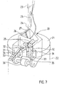
- FIG. 7 A second embodiment of this invention is shown in Fig. 7. Only the main operating components of the blade remover are shown in Fig. 7, the remaining components being omitted for clarity.
- the blade remover 20 of the second embodiment operates according to the same general principle as the blade remover shown in Figs. 1 and 2.
- the blade remover 20 is typically fitted to the lid 21 of a sharps container 22 so that the removed blades fall automatically into the container 22.
- the blade remover 20 is designed to remove a blade 24 from the boss on the tang 25 of a scalpel handle 23.
- the blade remover 20 comprises a mouth portion 26 having a channel 27 along which the scalpel 23 is inserted.
- the mouth 26 leads to a gate formed by a pair of opposed spring-loaded jaws 28 which are displaced apart by the leading tang 25 to accommodate scalpel handles of different width.
- the blade remover 20 can be used not only with conventional scalpels, but also scalpels with wider handles (of the type typically used in plastic surgery).
- the blade remover 20 also comprises a rocker block 30 which is pivotally mounted on pivot pins 33.
- a portion of the block 30 is bifurcated to form a pair of spaced legs 31, the free ends of which each have a raised or stepped portion 32.
- a web portion between the two legs 31 forms a contact surface 35.
- the rocker block 30 is lightly biased to a preferred position by a resilient strip or leaf spring 34.
- a guide roller 36 is also provided on the blade remover 20, downstream from the rocker block 30.
- the components of the blade remover 20 can be suitably made from moulded plastic components.
- the operation of the blade remover 20 is shown schematically in Figs. 8 to 11.
- a scalpel 23 When a scalpel 23 is inserted into the mouth 26 of the blade remover 20, the scalpel is guided by channel 27 in a substantially straight line path.
- the blade 24 passes over the spring loaded jaws 28 which are pushed apart by the tang 25 of the scalpel handle.
- the blade 24 passes between the rocker block 30 and the guide roller 36, as shown in Fig. 8. (The curved surface of the roller 36 serves to guide the blade 28 to the right thereof as depicted in Fig. 8).
- the heel of the blade 24 slides over the stepped end portions 32 of the legs 31 until the blade clears the stepped portions and drops down onto the lower flat surfaces of the legs 31. This produces an audible "click", thereby indicating to the user that the scalpel has been inserted the required distance, and may then be withdrawn along the same straight-line path.
- the scalpel 23 When the scalpel 23 is withdrawn, the rearward motion of the blade is obstructed by the riser surface of the stepped portions 32. As the heel of the blade is still lifted off the boss, and as withdrawal of the blade is prevented, the stepped portions 32 strip the blade 24 from the boss on tang 25 when the scalpel handle 23 is withdrawn (Fig. 11). The removed blade falls freely under gravity into the container below.
- scalpel blade removers have several advantages, including:
- Unused scalpel blades are normally provided in a sealed sterile package. At the conclusion of surgery, it is important that all blades used during the surgery be accounted for.
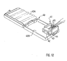
- a blade remover is incorporated in a small disposable container.
- a container 40 is formed by two hinged portions.
- a blade remover 41 is mounted in one of the hinged portions.
- the blade remover and the container 40 may suitably be made of moulded plastic components.
- the container 40 may also include a foam layer 40A for holding surgical needles and blades, as is known in the art.
- a magnetic layer 40B may be placed in the container for fixing suture needles and blades.
- the magnet 40B may be numbered to assist counting of used needles and blades.
- the blade remover 41 comprises a fixed block 42 having a contact surface 43.
- a rocker portion 44 is pivotally mounted above the fixed block 42 and is able to rock back and forth about its pivot axis.
- the rocker portion 44 On one side of its pivot axis (shown to the left in Fig. 12), the rocker portion 44 has a ramped contact surface 47 on its underside.
- the rocker portion 44 On the other side of the pivot axis, the rocker portion 44 is bifurcated into two legs 45. The free ends of the legs have stepped portions 46 on their underside, and their top sides are sloped downwardly at the free ends to form tapered inner corners.
- the operation of the blade remover is illustrated in Figs. 13 to 16.
- the blade remover 41 operates on the same principle as the blade removers of Figs. 2 and 7. Holding the scalpel handle 48, the user inserts the blade end of the scalpel into the blade remover 41 in a substantially straight line path. If the blade remover is orientated generally horizontal as shown in Fig. 12, the scalpel is inserted with the blade on its lower side. The blade 49 is inserted between the rocker portion 44 and the fixed block 42. The tang 50, on which the blade is mounted, passes between the legs 45 of the rocker portion 44 (Fig. 13).
- the side of the rocker portion 44 having the contact surface 47 is weighted more than the other side having the legs 44, so that in its rest position, the legs 45 are raised slightly to form a mouth therebelow for receiving the bladed scalpel.
- the rocker portion 44 pivots about its axis (in a clockwise manner when viewed as in Fig. 14). The pivoting of the rocker portion 44 causes the legs 45 to impart a force on the heel of the blade 49 on either side of the tang, transversely to the longitudinal axis of the scalpel 48, to lift the heel of the blade 49 off the tang.
- the blade 49 rides over the stepped portions 46 on the ends of legs 44, until the rear end of the blade 49 clears the stepped portions 46 (Fig. 15). Due to the resilient nature of the blade, it gives an audible "click” as it steps from the end portions 46 to the intermediate portion of the legs 45. This indicates that the scalpel 48 has been inserted the required distance.
- the scalpel 48 may then be withdrawn along the same straight line path (Fig. 16).
- the riser face of each stepped portion 46 obstructs the rearward movement of the blade 49.
- the stepped portions 46 strip the blade 49 from the tang 50.
- the loose blade is automatically received within the container half in which the blade remover 41 is located. After all the used blades have been removed and counted, the container 40 is simply closed and disposed.
- pivoting block 12 may be replaced by a linkage mechanism (not illustrated) which lifts the blade from the tang in response to the forward movement of the tang.
Abstract
Description
Claims (11)
- A scalpel blade remover (3) for removing a blade from a tang (6) of a scalpel (8), comprising;
means for receiving the tang (6) of the scalpel (8),
means for lifting the heel of the blade (5) off the tang (6), and
blade stop means for preventing rearward movement of the lifted blade such that the blade (5) is disengaged from the tang (6) upon withdrawal of the scalpel (8),
characterised in that the receiving means comprises a formation (9, 10) permitting the tang (6) to be inserted and removed from the blade remover (3) in a substantially straight-line path, and the lifting means comprises a mechanism (12) which is actuated by the forward movement of the tang (6) along that straight-line path to lift the heel of the blade (5) off the tang (6). - A blade remover as claimed in claim 1, wherein the mechanism comprises a moveable member (12) having first and second portions (15, 14), the moveable member being positioned such that the first portion (15) is contacted by the tang (6) when the tang (6) is operatively inserted into the blade remover (3), the moveable member (12) being moved by the physical urging of the tang (6) against the first portion (15), and wherein such movement of the moveable member (12) causes the second portion (14) thereof to apply a substantially transverse force to the heel of the blade (5) to lift it off the tang (6).
- A blade remover as claimed in claim 2, wherein the moveable member (12) is pivotable about an axis transverse to the path.
- A blade remover as claimed in claim 3, further comprising means (17) to bias the moveable member in one direction about the pivot axis.
- A blade remover as claimed in claim 2, wherein the first portion (15) comprises a contact surface generally aligned with the tang (6) in the path.
- A blade remover as claimed in claim 2, wherein the second portion (14) is bifurcated to form a pair of leg members, each located on opposite sides of the tang (6) and in juxtaposition with the blade (5) when the blade is inserted in the blade remover (3).
- A scalpel blade remover as claimed in claim 6, wherein the blade stop means comprises a stepped portion (46) on the free end of at least one of the leg members (45).
- A blade remover as claimed in claim 6, wherein the blade stop means is a pawl (16) located between the leg members (14) and opposed thereto.
- A blade remover as claimed in claim 8, wherein the pawl (16) is resiliently mounted.
- A blade remover as claimed in claim 1, wherein the blade remover is mounted to a container (1).
- A blade remover as claimed in claim 1, wherein the mechanism comprises a rocker block (12) mounted for pivotal movement about a pivot axis transverse to the insertion path, the rocker block being pivotable by the urging of the tang (6) against a contact surface (15) thereof, the rocker block having a lifting portion (14) spaced from the contact surface (15), the lifting portion (14) applying a transverse force to the heel of the blade (5) when the rocker block (12) is pivoted by the tang (6).
Applications Claiming Priority (4)
| Application Number | Priority Date | Filing Date | Title |
|---|---|---|---|
| AUPM7980A AUPM798094A0 (en) | 1994-09-09 | 1994-09-09 | A scalpel blade remover |
| AUPM7980/94 | 1994-09-09 | ||
| AUPM798094 | 1994-09-09 | ||
| PCT/AU1995/000585 WO1996007363A1 (en) | 1994-09-09 | 1995-09-08 | A scalpel blade remover |
Publications (3)
| Publication Number | Publication Date |
|---|---|
| EP0779797A1 EP0779797A1 (en) | 1997-06-25 |
| EP0779797A4 EP0779797A4 (en) | 1997-12-03 |
| EP0779797B1 true EP0779797B1 (en) | 2002-04-17 |
Family
ID=3782500
Family Applications (1)
| Application Number | Title | Priority Date | Filing Date |
|---|---|---|---|
| EP95931086A Expired - Lifetime EP0779797B1 (en) | 1994-09-09 | 1995-09-08 | A scalpel blade remover |
Country Status (18)
| Country | Link |
|---|---|
| US (1) | US5875533A (en) |
| EP (1) | EP0779797B1 (en) |
| JP (1) | JP3604394B2 (en) |
| KR (1) | KR100395170B1 (en) |
| CN (1) | CN1119130C (en) |
| AT (1) | ATE216211T1 (en) |
| AU (3) | AUPM798094A0 (en) |
| BR (1) | BR9509159A (en) |
| CA (1) | CA2185253C (en) |
| DE (1) | DE69526441T2 (en) |
| DK (1) | DK0779797T3 (en) |
| ES (1) | ES2174959T3 (en) |
| IL (1) | IL115228A0 (en) |
| MY (1) | MY138337A (en) |
| RU (1) | RU2144334C1 (en) |
| TW (1) | TW274509B (en) |
| WO (1) | WO1996007363A1 (en) |
| ZA (1) | ZA957554B (en) |
Families Citing this family (22)
| Publication number | Priority date | Publication date | Assignee | Title |
|---|---|---|---|---|
| ATE363339T1 (en) * | 1998-05-01 | 2007-06-15 | Gen Probe Inc | STIRRING DEVICE FOR THE FLUID CONTENTS OF A CONTAINER |
| US8596453B2 (en) * | 2002-11-12 | 2013-12-03 | Mike Hoftman | Scalpel blade remover and sharps container |
| AU2003901949A0 (en) * | 2003-04-24 | 2003-05-15 | Qlicksmart Pty Ltd | Scalpel blade remover |
| US9339266B2 (en) * | 2003-06-09 | 2016-05-17 | St. Joseph Health System | Method and apparatus for sharps protection |
| US8752700B1 (en) * | 2003-11-12 | 2014-06-17 | Moshe Mike Hoftman | Sharps container with blade remover, needle unsheather, latch and security alignment extensions |
| US20070039844A1 (en) * | 2005-08-22 | 2007-02-22 | Zyzelewski Mark E | Sharps Container with Integrated Blade Disarming Device |
| CN200991904Y (en) * | 2006-12-15 | 2007-12-19 | 亿品(香港)有限公司 | Art designing cutter capable of automatically changing blade |
| CN105618264B (en) * | 2009-05-15 | 2021-04-06 | 简·探针公司 | Method and apparatus for implementing automatic movement of a magnet in an instrument performing a magnetic separation procedure |
| US9622773B2 (en) | 2012-03-19 | 2017-04-18 | Aspen Surgical Products, Inc. | Side activated safety scalpel for left and right hand users with blade removal system |
| TWI579124B (en) * | 2012-03-26 | 2017-04-21 | 克利克智能有限公司 | Scalpel blade remover and method of removing a scalpel blade from tang of a scalpel |
| ITFI20120085A1 (en) * | 2012-04-24 | 2013-10-25 | Lucia Gargani | SAFETY REMOVAL DEVICE FOR BLADES FOR DISPOSABLE SCALPERS. |
| US9717521B2 (en) | 2012-09-06 | 2017-08-01 | Scalpal Llc | Surgical knife and tools adapted for simplified blade removal |
| AU2014218499A1 (en) * | 2013-02-20 | 2015-10-01 | Qlicksmart Pty Ltd | Method and apparatus for use in removing a blade from a scalpel |
| USD745155S1 (en) | 2013-03-14 | 2015-12-08 | Aspen Surgical Products, Inc. | Blade disarmer |
| US20160095614A1 (en) | 2014-10-03 | 2016-04-07 | Aspen Surgical Products, Inc. | Sharps blade applicator and storage device |
| US10064647B2 (en) | 2015-10-09 | 2018-09-04 | Aspen Surgical Products, Inc. | Scalpel blade remover |
| USD813390S1 (en) | 2016-01-15 | 2018-03-20 | Aspen Surgical Products, Inc. | Surgical scalpel blade attachment |
| US20170265882A1 (en) | 2016-03-21 | 2017-09-21 | Aspen Surgical Products, Inc. | Safety scalpel handle |
| CN110300556A (en) * | 2017-02-15 | 2019-10-01 | 奥尼克斯私人有限公司 | A kind of knife blade dismounting device |
| US11752615B2 (en) | 2018-03-07 | 2023-09-12 | Creative Edge Medical, Llc | Coupler for blades and handles |
| US11877640B2 (en) * | 2019-09-19 | 2024-01-23 | Carl Pickett | Razor drop |
| KR200497052Y1 (en) * | 2022-05-11 | 2023-07-12 | (주)디엑스엠 | Blade remover for mes |
Family Cites Families (14)
| Publication number | Priority date | Publication date | Assignee | Title |
|---|---|---|---|---|
| AU510256B2 (en) * | 1977-05-27 | 1980-06-19 | Smith & Nephew (Australia) Pty. Limited | Scalpel blade remover |
| US4106620A (en) * | 1977-10-03 | 1978-08-15 | Brimmer Frances M | Surgical blade dispenser |
| EP0034949A3 (en) * | 1980-02-26 | 1982-04-07 | SMITH & NEPHEW (AUSTRALIA) PROPRIETARY LIMITED | Scalpel blade remover and collector |
| US4378624A (en) * | 1981-02-17 | 1983-04-05 | Braintree Scientific, Inc. | Scalpel blade remover |
| US4386457A (en) * | 1981-05-22 | 1983-06-07 | Donald W. Coombs | Surgical blade remover-receptacle |
| US4746016A (en) * | 1987-03-26 | 1988-05-24 | The Research Foundation Of State University Of New York | Blade removal and/or mounting mechanism and dispenser, extractor-disposal apparatus including same |
| US5088173A (en) * | 1989-04-26 | 1992-02-18 | Kromer Martin W | One-time-use precision-blade-bending scalpel blade remover-receptacle |
| IE893007A1 (en) * | 1989-09-20 | 1991-03-27 | David Morgan | A device for removing a scalpel-blade from a scalpel-blade¹handle |
| US5035703A (en) * | 1990-05-09 | 1991-07-30 | Baskas Morris J | Disposable syringe needle and scalpel holder |
| US5163553A (en) * | 1991-10-16 | 1992-11-17 | Cantwell Jay S | Scalpel blade extractor and disposal unit |
| EP0569233A1 (en) * | 1992-05-05 | 1993-11-10 | Hausler Scientific Instruments (Pty) Limited | Sharps handling apparatus |
| US5361902A (en) * | 1992-06-05 | 1994-11-08 | Leonard Bloom | Surgical blade dispenser and disposal system for use during an operating procedure and method thereof |
| US5449068A (en) * | 1993-10-18 | 1995-09-12 | Devon Industries, Inc. | Surgical blade remover |
| US5699908A (en) * | 1996-04-25 | 1997-12-23 | Fryco, Inc. | Scalpel blade removal and storage apparatus |
-
1994
- 1994-09-09 AU AUPM7980A patent/AUPM798094A0/en not_active Abandoned
-
1995
- 1995-09-06 TW TW084109305A patent/TW274509B/zh not_active IP Right Cessation
- 1995-09-08 WO PCT/AU1995/000585 patent/WO1996007363A1/en active IP Right Grant
- 1995-09-08 DK DK95931086T patent/DK0779797T3/en active
- 1995-09-08 US US08/737,071 patent/US5875533A/en not_active Expired - Lifetime
- 1995-09-08 ES ES95931086T patent/ES2174959T3/en not_active Expired - Lifetime
- 1995-09-08 CA CA002185253A patent/CA2185253C/en not_active Expired - Lifetime
- 1995-09-08 IL IL11522895A patent/IL115228A0/en not_active IP Right Cessation
- 1995-09-08 AU AU34659/95A patent/AU686878B2/en not_active Expired
- 1995-09-08 JP JP50904596A patent/JP3604394B2/en not_active Expired - Lifetime
- 1995-09-08 AT AT95931086T patent/ATE216211T1/en not_active IP Right Cessation
- 1995-09-08 CN CN95192695A patent/CN1119130C/en not_active Expired - Lifetime
- 1995-09-08 AU AU30509/95A patent/AU665514B3/en not_active Ceased
- 1995-09-08 DE DE69526441T patent/DE69526441T2/en not_active Expired - Lifetime
- 1995-09-08 BR BR9509159A patent/BR9509159A/en not_active IP Right Cessation
- 1995-09-08 RU RU96119316/14A patent/RU2144334C1/en not_active IP Right Cessation
- 1995-09-08 ZA ZA957554A patent/ZA957554B/en unknown
- 1995-09-08 KR KR1019970701563A patent/KR100395170B1/en not_active IP Right Cessation
- 1995-09-08 EP EP95931086A patent/EP0779797B1/en not_active Expired - Lifetime
- 1995-09-08 MY MYPI95002672A patent/MY138337A/en unknown
Also Published As
| Publication number | Publication date |
|---|---|
| ES2174959T3 (en) | 2002-11-16 |
| IL115228A0 (en) | 1995-12-31 |
| CN1146715A (en) | 1997-04-02 |
| ZA957554B (en) | 1996-04-17 |
| EP0779797A1 (en) | 1997-06-25 |
| TW274509B (en) | 1996-04-21 |
| MY138337A (en) | 2009-05-29 |
| CA2185253C (en) | 2006-05-09 |
| KR100395170B1 (en) | 2004-01-24 |
| AU3465995A (en) | 1996-03-27 |
| DE69526441D1 (en) | 2002-05-23 |
| RU2144334C1 (en) | 2000-01-20 |
| CA2185253A1 (en) | 1996-03-14 |
| EP0779797A4 (en) | 1997-12-03 |
| AUPM798094A0 (en) | 1994-09-29 |
| DK0779797T3 (en) | 2002-08-19 |
| US5875533A (en) | 1999-03-02 |
| WO1996007363A1 (en) | 1996-03-14 |
| AU686878B2 (en) | 1998-02-12 |
| BR9509159A (en) | 1997-11-25 |
| DE69526441T2 (en) | 2002-12-12 |
| ATE216211T1 (en) | 2002-05-15 |
| AU665514B3 (en) | 1996-01-04 |
| JP3604394B2 (en) | 2004-12-22 |
| KR970705355A (en) | 1997-10-09 |
| CN1119130C (en) | 2003-08-27 |
| JPH10504983A (en) | 1998-05-19 |
Similar Documents
| Publication | Publication Date | Title |
|---|---|---|
| EP0779797B1 (en) | A scalpel blade remover | |
| US4903390A (en) | Scalpel blade remover and blade storage apparatus | |
| US4746016A (en) | Blade removal and/or mounting mechanism and dispenser, extractor-disposal apparatus including same | |
| US9717521B2 (en) | Surgical knife and tools adapted for simplified blade removal | |
| US6216868B1 (en) | Surgical blade system | |
| US5938027A (en) | Surgical blade system | |
| US5449068A (en) | Surgical blade remover | |
| US4971067A (en) | Biopsy instrument with a disposable cutting blade | |
| EP0392548B1 (en) | Multi-position latching mechanism for forceps | |
| US20060212058A1 (en) | Disposable safety surgical blade | |
| US7155795B2 (en) | Method for mounting a surgical blade onto a scalpel and for subsequently removing the blade from the scalpel using a package incorporating a pivotable flap | |
| EP0392547A1 (en) | Multi-position latching mechanism for forceps | |
| JP4528767B2 (en) | Dissecting blade cutter | |
| EP0857037A1 (en) | Disposable surgical safety scalpel | |
| NZ538442A (en) | Surgical scalpel with retractable guard | |
| NL8300324A (en) | DRAWER FOR MEDICAL CURVES. | |
| WO1999032375A1 (en) | Scalpel blade removal and storage apparatus | |
| CA2345812C (en) | Compact cassette for dental instruments | |
| WO1993007826A1 (en) | Scalpel blade extractor and disposal unit | |
| US5255422A (en) | Scalpel blade on-off tool | |
| US5406684A (en) | Sanitary surgical blade removal instrument | |
| US20040111853A1 (en) | Scalpel blade remover and sharps container | |
| JPH0260641A (en) | Spare blade mounting and detaching mechanism | |
| JPH056997Y2 (en) | ||
| WO1994012114A1 (en) | Instrument for handling scalpel blades |
Legal Events
| Date | Code | Title | Description |
|---|---|---|---|
| PUAI | Public reference made under article 153(3) epc to a published international application that has entered the european phase |
Free format text: ORIGINAL CODE: 0009012 |
|
| 17P | Request for examination filed |
Effective date: 19960916 |
|
| AK | Designated contracting states |
Kind code of ref document: A1 Designated state(s): AT BE CH DE DK ES FR GB GR IE IT LI LU MC NL PT SE |
|
| A4 | Supplementary search report drawn up and despatched |
Effective date: 19971016 |
|
| AK | Designated contracting states |
Kind code of ref document: A4 Designated state(s): AT BE CH DE DK ES FR GB GR IE IT LI LU MC NL PT SE |
|
| 17Q | First examination report despatched |
Effective date: 20000620 |
|
| GRAG | Despatch of communication of intention to grant |
Free format text: ORIGINAL CODE: EPIDOS AGRA |
|
| GRAG | Despatch of communication of intention to grant |
Free format text: ORIGINAL CODE: EPIDOS AGRA |
|
| GRAG | Despatch of communication of intention to grant |
Free format text: ORIGINAL CODE: EPIDOS AGRA |
|
| GRAH | Despatch of communication of intention to grant a patent |
Free format text: ORIGINAL CODE: EPIDOS IGRA |
|
| REG | Reference to a national code |
Ref country code: GB Ref legal event code: IF02 |
|
| GRAH | Despatch of communication of intention to grant a patent |
Free format text: ORIGINAL CODE: EPIDOS IGRA |
|
| GRAA | (expected) grant |
Free format text: ORIGINAL CODE: 0009210 |
|
| AK | Designated contracting states |
Kind code of ref document: B1 Designated state(s): AT BE CH DE DK ES FR GB GR IE IT LI LU MC NL PT SE |
|
| PG25 | Lapsed in a contracting state [announced via postgrant information from national office to epo] |
Ref country code: GR Free format text: LAPSE BECAUSE OF FAILURE TO SUBMIT A TRANSLATION OF THE DESCRIPTION OR TO PAY THE FEE WITHIN THE PRESCRIBED TIME-LIMIT Effective date: 20020417 |
|
| REF | Corresponds to: |
Ref document number: 216211 Country of ref document: AT Date of ref document: 20020515 Kind code of ref document: T |
|
| REG | Reference to a national code |
Ref country code: CH Ref legal event code: EP |
|
| REG | Reference to a national code |
Ref country code: IE Ref legal event code: FG4D |
|
| REF | Corresponds to: |
Ref document number: 69526441 Country of ref document: DE Date of ref document: 20020523 |
|
| PG25 | Lapsed in a contracting state [announced via postgrant information from national office to epo] |
Ref country code: PT Free format text: LAPSE BECAUSE OF FAILURE TO SUBMIT A TRANSLATION OF THE DESCRIPTION OR TO PAY THE FEE WITHIN THE PRESCRIBED TIME-LIMIT Effective date: 20020717 |
|
| REG | Reference to a national code |
Ref country code: DK Ref legal event code: T3 |
|
| PG25 | Lapsed in a contracting state [announced via postgrant information from national office to epo] |
Ref country code: LU Free format text: LAPSE BECAUSE OF NON-PAYMENT OF DUE FEES Effective date: 20020908 |
|
| PGFP | Annual fee paid to national office [announced via postgrant information from national office to epo] |
Ref country code: AT Payment date: 20020911 Year of fee payment: 8 |
|
| PGFP | Annual fee paid to national office [announced via postgrant information from national office to epo] |
Ref country code: CH Payment date: 20020916 Year of fee payment: 8 |
|
| PGFP | Annual fee paid to national office [announced via postgrant information from national office to epo] |
Ref country code: IE Payment date: 20020924 Year of fee payment: 8 |
|
| ET | Fr: translation filed | ||
| REG | Reference to a national code |
Ref country code: ES Ref legal event code: FG2A Ref document number: 2174959 Country of ref document: ES Kind code of ref document: T3 |
|
| PLBE | No opposition filed within time limit |
Free format text: ORIGINAL CODE: 0009261 |
|
| STAA | Information on the status of an ep patent application or granted ep patent |
Free format text: STATUS: NO OPPOSITION FILED WITHIN TIME LIMIT |
|
| PG25 | Lapsed in a contracting state [announced via postgrant information from national office to epo] |
Ref country code: MC Free format text: LAPSE BECAUSE OF NON-PAYMENT OF DUE FEES Effective date: 20030401 |
|
| 26N | No opposition filed |
Effective date: 20030120 |
|
| PG25 | Lapsed in a contracting state [announced via postgrant information from national office to epo] |
Ref country code: IE Free format text: LAPSE BECAUSE OF NON-PAYMENT OF DUE FEES Effective date: 20030908 Ref country code: AT Free format text: LAPSE BECAUSE OF NON-PAYMENT OF DUE FEES Effective date: 20030908 |
|
| PG25 | Lapsed in a contracting state [announced via postgrant information from national office to epo] |
Ref country code: LI Free format text: LAPSE BECAUSE OF NON-PAYMENT OF DUE FEES Effective date: 20030930 Ref country code: CH Free format text: LAPSE BECAUSE OF NON-PAYMENT OF DUE FEES Effective date: 20030930 |
|
| REG | Reference to a national code |
Ref country code: CH Ref legal event code: PL |
|
| REG | Reference to a national code |
Ref country code: IE Ref legal event code: MM4A |
|
| PGFP | Annual fee paid to national office [announced via postgrant information from national office to epo] |
Ref country code: SE Payment date: 20050906 Year of fee payment: 11 |
|
| PGFP | Annual fee paid to national office [announced via postgrant information from national office to epo] |
Ref country code: DK Payment date: 20050915 Year of fee payment: 11 |
|
| PG25 | Lapsed in a contracting state [announced via postgrant information from national office to epo] |
Ref country code: SE Free format text: LAPSE BECAUSE OF NON-PAYMENT OF DUE FEES Effective date: 20060909 |
|
| PG25 | Lapsed in a contracting state [announced via postgrant information from national office to epo] |
Ref country code: DK Free format text: LAPSE BECAUSE OF NON-PAYMENT OF DUE FEES Effective date: 20061002 |
|
| REG | Reference to a national code |
Ref country code: DK Ref legal event code: EBP |
|
| EUG | Se: european patent has lapsed | ||
| PGFP | Annual fee paid to national office [announced via postgrant information from national office to epo] |
Ref country code: DE Payment date: 20140924 Year of fee payment: 20 Ref country code: NL Payment date: 20140919 Year of fee payment: 20 |
|
| PGFP | Annual fee paid to national office [announced via postgrant information from national office to epo] |
Ref country code: ES Payment date: 20140922 Year of fee payment: 20 Ref country code: GB Payment date: 20140924 Year of fee payment: 20 |
|
| PGFP | Annual fee paid to national office [announced via postgrant information from national office to epo] |
Ref country code: IT Payment date: 20140924 Year of fee payment: 20 |
|
| PGFP | Annual fee paid to national office [announced via postgrant information from national office to epo] |
Ref country code: FR Payment date: 20140930 Year of fee payment: 20 |
|
| PGFP | Annual fee paid to national office [announced via postgrant information from national office to epo] |
Ref country code: BE Payment date: 20140919 Year of fee payment: 20 |
|
| REG | Reference to a national code |
Ref country code: DE Ref legal event code: R071 Ref document number: 69526441 Country of ref document: DE |
|
| REG | Reference to a national code |
Ref country code: GB Ref legal event code: PE20 Expiry date: 20150907 Ref country code: NL Ref legal event code: MK Effective date: 20150907 |
|
| PG25 | Lapsed in a contracting state [announced via postgrant information from national office to epo] |
Ref country code: GB Free format text: LAPSE BECAUSE OF EXPIRATION OF PROTECTION Effective date: 20150907 |
|
| REG | Reference to a national code |
Ref country code: ES Ref legal event code: FD2A Effective date: 20151229 |
|
| PG25 | Lapsed in a contracting state [announced via postgrant information from national office to epo] |
Ref country code: ES Free format text: LAPSE BECAUSE OF EXPIRATION OF PROTECTION Effective date: 20150909 |