EP0780644A2 - Refrigerator with improved beverage dispenser - Google Patents
Refrigerator with improved beverage dispenser Download PDFInfo
- Publication number
- EP0780644A2 EP0780644A2 EP96309208A EP96309208A EP0780644A2 EP 0780644 A2 EP0780644 A2 EP 0780644A2 EP 96309208 A EP96309208 A EP 96309208A EP 96309208 A EP96309208 A EP 96309208A EP 0780644 A2 EP0780644 A2 EP 0780644A2
- Authority
- EP
- European Patent Office
- Prior art keywords
- door
- valve
- beverage
- container
- refrigerator according
- Prior art date
- Legal status (The legal status is an assumption and is not a legal conclusion. Google has not performed a legal analysis and makes no representation as to the accuracy of the status listed.)
- Withdrawn
Links
- 235000013361 beverage Nutrition 0.000 title claims abstract description 25
- 238000001816 cooling Methods 0.000 claims abstract description 10
- 238000007789 sealing Methods 0.000 claims description 11
- XLYOFNOQVPJJNP-UHFFFAOYSA-N water Substances O XLYOFNOQVPJJNP-UHFFFAOYSA-N 0.000 description 15
- 238000004140 cleaning Methods 0.000 description 4
- 238000010276 construction Methods 0.000 description 2
- 239000000463 material Substances 0.000 description 2
- 229920003023 plastic Polymers 0.000 description 2
- 239000004033 plastic Substances 0.000 description 2
- 238000007710 freezing Methods 0.000 description 1
- 230000008014 freezing Effects 0.000 description 1
- 239000011521 glass Substances 0.000 description 1
- 238000012986 modification Methods 0.000 description 1
- 230000004048 modification Effects 0.000 description 1
- 235000015205 orange juice Nutrition 0.000 description 1
Images

Classifications
-
- B—PERFORMING OPERATIONS; TRANSPORTING
- B67—OPENING, CLOSING OR CLEANING BOTTLES, JARS OR SIMILAR CONTAINERS; LIQUID HANDLING
- B67D—DISPENSING, DELIVERING OR TRANSFERRING LIQUIDS, NOT OTHERWISE PROVIDED FOR
- B67D3/00—Apparatus or devices for controlling flow of liquids under gravity from storage containers for dispensing purposes
- B67D3/0009—Apparatus or devices for controlling flow of liquids under gravity from storage containers for dispensing purposes provided with cooling arrangements
-
- F—MECHANICAL ENGINEERING; LIGHTING; HEATING; WEAPONS; BLASTING
- F25—REFRIGERATION OR COOLING; COMBINED HEATING AND REFRIGERATION SYSTEMS; HEAT PUMP SYSTEMS; MANUFACTURE OR STORAGE OF ICE; LIQUEFACTION SOLIDIFICATION OF GASES
- F25D—REFRIGERATORS; COLD ROOMS; ICE-BOXES; COOLING OR FREEZING APPARATUS NOT OTHERWISE PROVIDED FOR
- F25D11/00—Self-contained movable devices, e.g. domestic refrigerators
-
- B—PERFORMING OPERATIONS; TRANSPORTING
- B67—OPENING, CLOSING OR CLEANING BOTTLES, JARS OR SIMILAR CONTAINERS; LIQUID HANDLING
- B67D—DISPENSING, DELIVERING OR TRANSFERRING LIQUIDS, NOT OTHERWISE PROVIDED FOR
- B67D3/00—Apparatus or devices for controlling flow of liquids under gravity from storage containers for dispensing purposes
- B67D3/04—Liquid-dispensing taps or cocks adapted to seal and open tapping holes of casks, e.g. for beer
-
- F—MECHANICAL ENGINEERING; LIGHTING; HEATING; WEAPONS; BLASTING
- F25—REFRIGERATION OR COOLING; COMBINED HEATING AND REFRIGERATION SYSTEMS; HEAT PUMP SYSTEMS; MANUFACTURE OR STORAGE OF ICE; LIQUEFACTION SOLIDIFICATION OF GASES
- F25D—REFRIGERATORS; COLD ROOMS; ICE-BOXES; COOLING OR FREEZING APPARATUS NOT OTHERWISE PROVIDED FOR
- F25D23/00—General constructional features
- F25D23/12—Arrangements of compartments additional to cooling compartments; Combinations of refrigerators with other equipment, e.g. stove
- F25D23/126—Water cooler
-
- F—MECHANICAL ENGINEERING; LIGHTING; HEATING; WEAPONS; BLASTING
- F25—REFRIGERATION OR COOLING; COMBINED HEATING AND REFRIGERATION SYSTEMS; HEAT PUMP SYSTEMS; MANUFACTURE OR STORAGE OF ICE; LIQUEFACTION SOLIDIFICATION OF GASES
- F25D—REFRIGERATORS; COLD ROOMS; ICE-BOXES; COOLING OR FREEZING APPARATUS NOT OTHERWISE PROVIDED FOR
- F25D2400/00—General features of, or devices for refrigerators, cold rooms, ice-boxes, or for cooling or freezing apparatus not covered by any other subclass
- F25D2400/04—Refrigerators with a horizontal mullion
Definitions
- This invention relates to a refrigerator with a beverage dispenser, which allows a chilled beverage to be dispensed from the outside of the refrigerator.
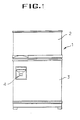
- FIG. 1 A prior art refrigerator with a beverage dispenser is shown in Figure 1, which includes a main body 1, with doors 2 and 3 that provide access to freezing and refrigerating compartments.
- the door 3 is provided with a beverage dispenser 4, which is commonly used to provide a supply of chilled water.
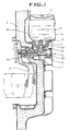
- the door 3 of the refrigerator which provides access to its refrigerating compartment or cooling chamber, is shown in cross section.
- Chilled water W is dispensed through a cylindrical valve 5, from an outlet orifice 5a, under the control of a lever 6 which actuates the valve when a cup C or like receptacle for the beverage, is pressed against it.
- the lever 6 actuates a slidable valve member 7 within the valve 5 against the force of a spring 8b.
- the chilled water W is held in a container 9 with an upper screw cap 10 and a lower screw fitted cap 11 that contains a slidable valve body 12, which is pressed downwardly by a spring 8a in order to maintain a valve head 13 closed.
- the lever 6 When the lever 6 is actuated, the slidable valve member 7 lifts the valve member 12 so as to allow the chilled water to flow through the valve to the orifice 5a.
- water is discharged from the container 9 into the receptacle C.
- the container 9 is thus mounted on the inside of the door, which results in a bulky and inconvenient arrangement. Furthermore, the dispenser is complicated to assemble due to the large number of component parts, and furthermore is inconvenient for cleaning purposes because the slide member of the valve 5 must be separated from the refrigerator body . Also, because the container 9 is mounted on the door, there is a limit to the quantity of water that can be stored for practical purposes, without making the door too bulky or cumbersome.
- the container is mounted separate from the door, and the door includes an opening through which the orifice extends when the door is closed, for dispensing the beverage.
- the container can be mounted on the main body of the refrigerator, in the cooling chamber, to permit the volumetric capacity of the container to be increased, irrespective of the loading on the door.
- valve construction can be substantially simplified, which facilitates cleaning, Means may be provided between the opening and the dispenser orifice, to provide a seal when the door is closed, so as to prevent cold air leaking from the refrigerator.
- the container may be held on the main body, in the chamber, by means of a releasible lock which conveniently comprises a hinged detent which releasably grips the underside of the container.
- a valve may be provided operable by a control device on the door, when it is closed.
- the control device may operate by means of a magnetic force to actuate the valve.
- the valve may include a movable valve member that includes a first magnet
- the control device may include a movable second magnet which cooperates with the first magnet when the door is closed, in order to move the valve member.
- the refrigerator according to the invention is shown, with a cooling chamber or refrigerating compartment 21, accessible by means of a door 22 which is shown open.
- a container 40 for chilled water is shown in the upper left hand side of the cooling chamber 21, with a protruding valve 30 for dispensing the chilled water.
- the valve 30 together with its outlet orifice extends through an opening 24 in the door into a recess 23.
- a receptacle such as a cup or glass can be inserted in to the recess 23, so as to open the valve 30 and fill the cup with chilled water.
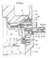
- the water container 40 is of a generally rectangular configuration, typically made of plastics material.
- the container 40 is slidably received on a horizontally disposed support surface 75 that is built into the interior of the cooling chamber 21 in the main body 1.
- the support surface 75 is provided along its outer edge with a spring loaded detent 80 that is shown in more detail in insert A shown in hatched outline, in Figure 4.
- the spring loaded detent 80 is pivoted about a shaft 85 and biased by a spring 82 so that a locating lug 84 can cooperate with flange 92 on the underside of the container 40 in order realisably to locate it in place.
- the container 40 is locked in position within the cooling chamber 21, but can be released in order to refill it or for cleaning purposes, by operating the spring loaded detent 80.
- the valve 30 includes a valve casing 31 that is threadingly received on a flange 41 integrally formed around a water outlet opening in the container 40.
- the valve casing 31 has an outlet orifice 31a for dispensing chilled water.
- a valve member with a main body 35 is disposed within the casing 31.
- the valve member includes an elongate valve stem 36 coupled to the main body 35, which is slidably received between flanges 37 in the outlet opening of the container 40.
- a spring 38 is disposed on the stem 36 between the flanges 37 and the main body 35.
- a permanent magnet 34 is mounted in a recess in the main body 35 and is covered by a washer 33.
- the interior of the casing 31 provides a valve seat 32.
- the washer 33 on the valve member is biased against the seat 32 by the spring 38.
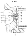
- valve 30 is opened and closed by means of a slidable, generally L-shaped control lever 52.
- a second permanent magnet 51 is mounted on the lever 52.
- the lever 52 is slidably mounted in a rail 53 and can be reciprocated back and forth against the force of a spring 54 mounted in a recess 55.
- sealing means 60 is provided in order to produce a seal between the valve 30 where it protrudes through the opening 24.
- the sealing means 60 includes a first annular, axially compressible sealing member 63 made of plastics material, which is received on the flange 41 of the container 40.
- the first sealing member cooperates with a second annular sealing member that includes an annular mounting member 61 received in a circular flange around the opening 24, which itself receives an annular lip member 62 which, when the door is closed, is pressed against the first sealing member 63 in order to provide an airtight seal that prevents cold air from leaking out of the refrigerator and warm air entering from outside.
- the first and second sealing members readily separate and do not impede door opening.
- the dispenser may conveniently be used to dispense chilled water
- other beverages could be stored in the container 40, for example orange juice.
- the construction of the beverage dispenser is much simplified as compared with the aforementioned prior art device.
- the capacity of the storage container 40 can be increased significantly.
- the container is securely held in place by means of the spring loaded detent 80 so that the act of opening the door will not dislodge it from its mounting, but it can readily be released for cleaning and refilling.
Abstract
A refrigerator 20 includes an improved beverage dispenser that includes a container 40 for the beverage, disposed within the cooling chamber 21 of the refrigerator, and a dispensing valve 30 with an orifice 31a accessible from outside the refrigerator, which extends through an opening 24 in the door. The beverage is dispensed by operating a lever 52 which moves a slidable valve member 35 against the force of spring 38, by means of the repulsive force between permanent magnets 51, 34. A seal 60 is provided by members 61, 62, 63 around the valve 30, where it extends through the hole 24.
Description
- This invention relates to a refrigerator with a beverage dispenser, which allows a chilled beverage to be dispensed from the outside of the refrigerator.
- A prior art refrigerator with a beverage dispenser is shown in Figure 1, which includes a main body 1, with
doors door 3 is provided with abeverage dispenser 4, which is commonly used to provide a supply of chilled water. - Referring to Figure 2, the
door 3 of the refrigerator, which provides access to its refrigerating compartment or cooling chamber, is shown in cross section. Chilled water W is dispensed through acylindrical valve 5, from anoutlet orifice 5a, under the control of alever 6 which actuates the valve when a cup C or like receptacle for the beverage, is pressed against it. Thelever 6 actuates aslidable valve member 7 within thevalve 5 against the force of aspring 8b. - The chilled water W is held in a
container 9 with anupper screw cap 10 and a lower screw fittedcap 11 that contains a slidable valve body 12, which is pressed downwardly by aspring 8a in order to maintain avalve head 13 closed. When thelever 6 is actuated, theslidable valve member 7 lifts the valve member 12 so as to allow the chilled water to flow through the valve to theorifice 5a. Thus, water is discharged from thecontainer 9 into the receptacle C. - The
container 9 is thus mounted on the inside of the door, which results in a bulky and inconvenient arrangement. Furthermore, the dispenser is complicated to assemble due to the large number of component parts, and furthermore is inconvenient for cleaning purposes because the slide member of thevalve 5 must be separated from the refrigerator body . Also, because thecontainer 9 is mounted on the door, there is a limit to the quantity of water that can be stored for practical purposes, without making the door too bulky or cumbersome. - The present invention seeks to overcome these problems. In accordance with the invention, the container is mounted separate from the door, and the door includes an opening through which the orifice extends when the door is closed, for dispensing the beverage.
- Thus, in accordance with the invention, the container can be mounted on the main body of the refrigerator, in the cooling chamber, to permit the volumetric capacity of the container to be increased, irrespective of the loading on the door.
- Furthermore, because the orifice extends through an opening in the door, the valve construction can be substantially simplified, which facilitates cleaning, Means may be provided between the opening and the dispenser orifice, to provide a seal when the door is closed, so as to prevent cold air leaking from the refrigerator.
- The container may be held on the main body, in the chamber, by means of a releasible lock which conveniently comprises a hinged detent which releasably grips the underside of the container.
- In order to control flow of beverage through the orifice, a valve may be provided operable by a control device on the door, when it is closed. The control device may operate by means of a magnetic force to actuate the valve.
- The valve may include a movable valve member that includes a first magnet, and the control device may include a movable second magnet which cooperates with the first magnet when the door is closed, in order to move the valve member.
- In order that the invention may be more fully understood, an embodiment thereof will now be described by way of illustrative example with reference to the accompanying drawings in which:
- Figure 1 is an elevational front view of a conventional refrigerator including a beverage dispenser;
- Figure 2 is an enlarged cross sectional view of a portion of the door of the conventional refrigerator, showing the beverage dispenser in more detail;
- Figure 3 is a schematic front elevational view of a refrigerator in accordance with the invention, with the door to its cooling chamber shown open;
- Figure 4 is a schematic partial cross sectional view of the door of the refrigerator, when closed, together with a portion of the beverage dispenser;
- Figure 5 is a corresponding cross sectional view from above of the configuration shown in Figure 4; and
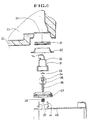
- Figure 6 is a schematic exploded cross sectional view of the beverage dispenser, illustrating its valve, together with a portion of the door.
- Referring to Figure 3, the refrigerator according to the invention is shown, with a cooling chamber or refrigerating
compartment 21, accessible by means of adoor 22 which is shown open. Acontainer 40 for chilled water is shown in the upper left hand side of thecooling chamber 21, with a protrudingvalve 30 for dispensing the chilled water. When thedoor 22 of the refrigerator is closed onto the main body 1, thevalve 30 together with its outlet orifice extends through an opening 24 in the door into arecess 23. As will be explained in more detail hereinafter, a receptacle such as a cup or glass can be inserted in to therecess 23, so as to open thevalve 30 and fill the cup with chilled water. - Referring now to Figure 4, the
water container 40 is of a generally rectangular configuration, typically made of plastics material. Thecontainer 40 is slidably received on a horizontally disposedsupport surface 75 that is built into the interior of thecooling chamber 21 in the main body 1. Thesupport surface 75 is provided along its outer edge with a spring loadeddetent 80 that is shown in more detail in insert A shown in hatched outline, in Figure 4. The spring loadeddetent 80 is pivoted about ashaft 85 and biased by aspring 82 so that a locatinglug 84 can cooperate withflange 92 on the underside of thecontainer 40 in order realisably to locate it in place. Thus, in use, thecontainer 40 is locked in position within thecooling chamber 21, but can be released in order to refill it or for cleaning purposes, by operating the spring loaded detent 80. - Referring to Figures 4, 5 and 6, the
valve 30 includes avalve casing 31 that is threadingly received on aflange 41 integrally formed around a water outlet opening in thecontainer 40. Thevalve casing 31 has anoutlet orifice 31a for dispensing chilled water. A valve member with amain body 35 is disposed within thecasing 31. The valve member includes anelongate valve stem 36 coupled to themain body 35, which is slidably received betweenflanges 37 in the outlet opening of thecontainer 40. Aspring 38 is disposed on thestem 36 between theflanges 37 and themain body 35. Apermanent magnet 34 is mounted in a recess in themain body 35 and is covered by awasher 33. The interior of thecasing 31 provides avalve seat 32. Thewasher 33 on the valve member is biased against theseat 32 by thespring 38. - As shown in Figures 4 and 5, the
valve 30 is opened and closed by means of a slidable, generally L-shaped control lever 52. Referring to Figure 5, a secondpermanent magnet 51 is mounted on thelever 52. Thelever 52 is slidably mounted in arail 53 and can be reciprocated back and forth against the force of aspring 54 mounted in arecess 55. - When it is desired to dispense chilled water, with the refrigerated
door 22 closed, as shown in Figure 4, a cup or like receptacle (not shown) is inserted into therecess 23 and pushed against thelever 52 so as to drive it into therecess 55, against the force ofspring 54. As a result, the entire lever slides inwardly alongrail 53 so as to move themagnet 51 closer to themagnet 34 mounted in the valve member. The repulsive force between the first andsecond magnets main body 35 to be moved against the force ofspring 38, so as to lift thewasher 33 from thevalve seat 31. As a result, water flows through the valve to the outlet orifice 31a and into the cup. When the cup is removed, thespring 54 drives thelever 52 outwardly, so thatmagnet 51 is moved away from thevalve 30 thereby reducing the magnetic force produced between the magnets, so thatspring 38 closes thevalve 30. - Also, in accordance with the invention, sealing means 60 is provided in order to produce a seal between the
valve 30 where it protrudes through theopening 24. The sealing means 60 includes a first annular, axiallycompressible sealing member 63 made of plastics material, which is received on theflange 41 of thecontainer 40. The first sealing member cooperates with a second annular sealing member that includes anannular mounting member 61 received in a circular flange around the opening 24, which itself receives anannular lip member 62 which, when the door is closed, is pressed against thefirst sealing member 63 in order to provide an airtight seal that prevents cold air from leaking out of the refrigerator and warm air entering from outside. When thedoor 22 is opened, the first and second sealing members readily separate and do not impede door opening. - Many modifications and variations fall within the scope of the invention defined in the claims hereinafter. For example, whilst the dispenser may conveniently be used to dispense chilled water, other beverages could be stored in the
container 40, for example orange juice. It will be seen that the construction of the beverage dispenser is much simplified as compared with the aforementioned prior art device. Furthermore, the capacity of thestorage container 40 can be increased significantly. The container is securely held in place by means of the spring loadeddetent 80 so that the act of opening the door will not dislodge it from its mounting, but it can readily be released for cleaning and refilling.
Claims (11)
- A refrigerator (20) including a cooling chamber (21), a door (22) to the chamber, and a beverage dispenser that includes a container (40) for the beverage within the chamber and a dispensing orifice (31a) accessible from outside the refrigerator for dispensing the beverage when the door is closed characterised in that the container (40) is mounted separate from the door, and the door includes an opening (24) through which the orifice extends when the door is closed, for dispensing the beverage.
- A refrigerator according to claim 1 wherein the cooling chamber (21) is disposed in a main body on which the door is mounted, and the container (40) is mounted on the main body, in the chamber.
- A refrigerator according to claim 2 including releasible locking means (80, 84, 92) that locates the container on the main body.
- A refrigerator according to claim 3 wherein the releasible locking means comprises a hinged detent (80) for realisably gripping the underside of the container.
- A refrigerator according to any preceding claim including means (60) for sealing the opening (24) when the door is closed.
- A refrigerator according to claim 5 wherein the sealing means includes a first sealing member (63) on the container and a second sealing member (61, 62) on the door .
- A refrigerator according to any preceding claim including a valve (30) for controlling flow of the beverage through the orifice (31a), and a control device (52) on the door for opening the valve when the door is closed.
- A refrigerator according to claim 7 wherein the control device (52) is operable to apply a magnetic force for actuating the valve.
- A refrigerator according to claim 8 wherein the valve (30) includes a movable valve member that includes a first magnet (34), and the control device includes a movable second magnet (51) which cooperates with the first magnet when the door is closed for moving the valve member.
- A refrigerator according to claim 9 wherein the valve includes a valve seat (32) and a spring (38) which biases the valve member against the seat, and the magnets cooperate for moving the valve member from the seat against the spring bias, to dispense the beverage.
- A refrigerator according to any one of claims 7 to 10 wherein the control device comprises a lever (52) mounted on the door and operable by pushing a receptacle to receive the beverage against it such as to cause the beverage to pour from the orifice into the receptacle.
Applications Claiming Priority (6)
| Application Number | Priority Date | Filing Date | Title |
|---|---|---|---|
| KR19950052134 | 1995-12-19 | ||
| KR19950052135 | 1995-12-19 | ||
| KR9552134 | 1995-12-19 | ||
| KR9552135 | 1995-12-19 | ||
| KR9647121 | 1996-10-21 | ||
| KR1019960047121A KR100187284B1 (en) | 1995-12-19 | 1996-10-21 | Water dispenser of a refrigerator |
Publications (2)
| Publication Number | Publication Date |
|---|---|
| EP0780644A2 true EP0780644A2 (en) | 1997-06-25 |
| EP0780644A3 EP0780644A3 (en) | 1998-01-28 |
Family
ID=27349261
Family Applications (1)
| Application Number | Title | Priority Date | Filing Date |
|---|---|---|---|
| EP96309208A Withdrawn EP0780644A3 (en) | 1995-12-19 | 1996-12-17 | Refrigerator with improved beverage dispenser |
Country Status (5)
| Country | Link |
|---|---|
| US (1) | US5791523A (en) |
| EP (1) | EP0780644A3 (en) |
| JP (1) | JP2804018B2 (en) |
| KR (1) | KR100187284B1 (en) |
| CN (1) | CN1156813A (en) |
Cited By (8)
| Publication number | Priority date | Publication date | Assignee | Title |
|---|---|---|---|---|
| GB2333827A (en) * | 1998-01-28 | 1999-08-04 | Alan Didier | Cold water box |
| WO2000011420A1 (en) * | 1998-08-25 | 2000-03-02 | Maytag Corporation | Refrigerator with varying width fresh food and freezer compartments |
| GB2401169A (en) * | 2003-03-19 | 2004-11-03 | Lg Electronics Inc | Dispenser for a refrigerator |
| CN100359273C (en) * | 2003-03-12 | 2008-01-02 | 乐金电子(天津)电器有限公司 | Bucket installing structure of refrigerator |
| CN100375879C (en) * | 2004-04-30 | 2008-03-19 | 乐金电子(天津)电器有限公司 | Distributor for refrigerator |
| WO2008035201A2 (en) | 2006-09-21 | 2008-03-27 | BSH Bosch und Siemens Hausgeräte GmbH | Improvements to a water dispensing device mounted in refrigerator doors |
| WO2010043012A2 (en) * | 2008-10-16 | 2010-04-22 | Whirpool S.A. | Valve for providing cold water, disposed on the door of a refrigerator |
| EP3683527A1 (en) * | 2015-01-09 | 2020-07-22 | LG Electronics Inc. | Refrigerator |
Families Citing this family (51)
| Publication number | Priority date | Publication date | Assignee | Title |
|---|---|---|---|---|
| JP3186772B2 (en) * | 1995-07-26 | 2001-07-11 | サムソン エレクトロニクス カンパニー リミテッド | Refrigerator water distributor |
| US6449970B1 (en) | 1999-11-10 | 2002-09-17 | Shurflo Pump Manufacturing Company, Inc. | Refrigeration apparatus and method for a fluid dispensing device |
| US6354341B1 (en) | 1999-11-10 | 2002-03-12 | Shurflo Pump Manufacturing Co., Inc. | Rapid comestible fluid dispensing apparatus and method |
| US6443335B1 (en) | 1999-11-10 | 2002-09-03 | Shurflo Pump Manufacturing Company, Inc. | Rapid comestible fluid dispensing apparatus and method employing a diffuser |
| US6360556B1 (en) | 1999-11-10 | 2002-03-26 | Shurflo Pump Manufacturing Company, Inc. | Apparatus and method for controlling fluid delivery temperature in a dispensing apparatus |
| US6354342B1 (en) | 1999-11-10 | 2002-03-12 | Shurflo Pump Manufacturing Company, Inc. | Hand-held rapid dispensing apparatus and method |
| US6799085B1 (en) | 2000-06-08 | 2004-09-28 | Beverage Works, Inc. | Appliance supply distribution, dispensing and use system method |
| US6751525B1 (en) | 2000-06-08 | 2004-06-15 | Beverage Works, Inc. | Beverage distribution and dispensing system and method |
| US7754025B1 (en) | 2000-06-08 | 2010-07-13 | Beverage Works, Inc. | Dishwasher having a door supply housing which holds dish washing supply for multiple wash cycles |
| US7083071B1 (en) | 2000-06-08 | 2006-08-01 | Beverage Works, Inc. | Drink supply canister for beverage dispensing apparatus |
| US6708741B1 (en) | 2000-08-24 | 2004-03-23 | Ocean Spray Cranberries, Inc. | Beverage dispenser |
| US7653710B2 (en) | 2002-06-25 | 2010-01-26 | Qst Holdings, Llc. | Hardware task manager |
| US7249242B2 (en) | 2002-10-28 | 2007-07-24 | Nvidia Corporation | Input pipeline registers for a node in an adaptive computing engine |
| US6836839B2 (en) | 2001-03-22 | 2004-12-28 | Quicksilver Technology, Inc. | Adaptive integrated circuitry with heterogeneous and reconfigurable matrices of diverse and adaptive computational units having fixed, application specific computational elements |
| US7752419B1 (en) | 2001-03-22 | 2010-07-06 | Qst Holdings, Llc | Method and system for managing hardware resources to implement system functions using an adaptive computing architecture |
| US7962716B2 (en) | 2001-03-22 | 2011-06-14 | Qst Holdings, Inc. | Adaptive integrated circuitry with heterogeneous and reconfigurable matrices of diverse and adaptive computational units having fixed, application specific computational elements |
| US6577678B2 (en) | 2001-05-08 | 2003-06-10 | Quicksilver Technology | Method and system for reconfigurable channel coding |
| US7046635B2 (en) | 2001-11-28 | 2006-05-16 | Quicksilver Technology, Inc. | System for authorizing functionality in adaptable hardware devices |
| US6986021B2 (en) | 2001-11-30 | 2006-01-10 | Quick Silver Technology, Inc. | Apparatus, method, system and executable module for configuration and operation of adaptive integrated circuitry having fixed, application specific computational elements |
| US8412915B2 (en) | 2001-11-30 | 2013-04-02 | Altera Corporation | Apparatus, system and method for configuration of adaptive integrated circuitry having heterogeneous computational elements |
| US6564975B1 (en) | 2001-12-11 | 2003-05-20 | Hamilton Beach/Proctor Silex, Inc. | Hot beverage maker with cup-actuated dispenser |
| US20060283332A1 (en) | 2001-12-11 | 2006-12-21 | Garman Michael H | Hot beverage maker |
| US7461586B2 (en) * | 2001-12-11 | 2008-12-09 | Hamilton Beach Brands, Inc. | Hot beverage maker with cup-actuated, low-drip dispenser |
| US20060196365A1 (en) * | 2001-12-11 | 2006-09-07 | Garman Michael H | Combined water cooler and hot beverage maker |
| US7215701B2 (en) | 2001-12-12 | 2007-05-08 | Sharad Sambhwani | Low I/O bandwidth method and system for implementing detection and identification of scrambling codes |
| US7403981B2 (en) | 2002-01-04 | 2008-07-22 | Quicksilver Technology, Inc. | Apparatus and method for adaptive multimedia reception and transmission in communication environments |
| US6574984B1 (en) * | 2002-02-07 | 2003-06-10 | Camco Inc. | Refrigerator door mounted water dispensing assembly |
| US7660984B1 (en) | 2003-05-13 | 2010-02-09 | Quicksilver Technology | Method and system for achieving individualized protected space in an operating system |
| US7328414B1 (en) | 2003-05-13 | 2008-02-05 | Qst Holdings, Llc | Method and system for creating and programming an adaptive computing engine |
| US8108656B2 (en) | 2002-08-29 | 2012-01-31 | Qst Holdings, Llc | Task definition for specifying resource requirements |
| US7937591B1 (en) | 2002-10-25 | 2011-05-03 | Qst Holdings, Llc | Method and system for providing a device which can be adapted on an ongoing basis |
| US8276135B2 (en) | 2002-11-07 | 2012-09-25 | Qst Holdings Llc | Profiling of software and circuit designs utilizing data operation analyses |
| KR100546904B1 (en) * | 2003-03-31 | 2006-01-26 | 엘지전자 주식회사 | Working structure of behavior switch in dispenser for refrigerator |
| KR100906889B1 (en) | 2003-03-31 | 2009-07-08 | 엘지전자 주식회사 | Water supply switch device for dispenser in refrigerator |
| US6973803B2 (en) * | 2003-04-28 | 2005-12-13 | Olive Bentley J | Refrigerator water supply systems |
| KR101251654B1 (en) * | 2004-01-20 | 2013-04-05 | 쓰리엠 이노베이티브 프로퍼티즈 컴파니 | Water dispenser with water filter for a refrigerator |
| DE102005021551A1 (en) * | 2005-05-10 | 2006-11-16 | BSH Bosch und Siemens Hausgeräte GmbH | Refrigerating appliance with a water pipe |
| US7343757B2 (en) * | 2005-08-11 | 2008-03-18 | Whirlpool Corporation | Integrated center rail dispenser |
| MXPA06005487A (en) * | 2006-05-15 | 2007-11-14 | Whirlpool Mexico S A De C V | Purified water filtration and dispensing system. |
| RU2485878C2 (en) * | 2008-09-18 | 2013-06-27 | Конинклейке Филипс Электроникс Н.В. | Brewing device for coffee makers and similar devices |
| DE102008055009A1 (en) * | 2008-12-19 | 2010-06-24 | BSH Bosch und Siemens Hausgeräte GmbH | Water valve and household refrigeration appliance |
| EP2526494B1 (en) | 2010-01-21 | 2020-01-15 | SVIRAL, Inc. | A method and apparatus for a general-purpose, multiple-core system for implementing stream-based computations |
| US8523022B2 (en) * | 2011-09-09 | 2013-09-03 | Imi Cornelius, Inc. | System and method for dispensing a predetermined amount of a fluid |
| DE102013212809A1 (en) * | 2013-07-01 | 2015-01-08 | Brainlink Gmbh | Beverage preparation system with disposable container |
| US20160370104A1 (en) * | 2015-06-18 | 2016-12-22 | Dongbu Daewoo Electronics Corporation | Refrigerator and beverage supplying method using the same |
| WO2017026133A1 (en) * | 2015-08-10 | 2017-02-16 | シャープ株式会社 | Beverage supply apparatus and refrigerator |
| CN109312978B (en) * | 2016-07-01 | 2021-07-20 | 夏普株式会社 | Beverage supply device and door structure |
| KR102211118B1 (en) * | 2017-12-26 | 2021-02-03 | 코웨이 주식회사 | Water discharging apparatus |
| US10865092B1 (en) | 2019-08-06 | 2020-12-15 | Haier Us Appliance Solutions, Inc. | Modular beverage-dispensing assembly for a refrigerator appliance |
| JP7455370B2 (en) * | 2020-04-02 | 2024-03-26 | アクア株式会社 | Container connection module and refrigerator with it |
| TR202100613A2 (en) | 2021-01-15 | 2022-07-21 | Arçeli̇k Anoni̇m Şi̇rketi̇ | A cooling appliance having a water dispensing unit |
Citations (4)
| Publication number | Priority date | Publication date | Assignee | Title |
|---|---|---|---|---|
| US2751757A (en) * | 1955-06-14 | 1956-06-26 | William E Hobbs | Liquid dispenser for refrigerators |
| US2777304A (en) * | 1953-12-09 | 1957-01-15 | Avco Mfg Corp | Water dispenser for refrigerator |
| DE3024590A1 (en) * | 1980-06-28 | 1982-01-28 | Bosch-Siemens Hausgeräte GmbH, 7000 Stuttgart | Combined refrigerator-freezer with drink cooler - has additional carboniser and preselector controlled mixer with drink concentrate |
| EP0165792A1 (en) * | 1984-06-18 | 1985-12-27 | The Cornelius Company | Method and apparatus for cooling and dispensing beverage |
Family Cites Families (6)
| Publication number | Priority date | Publication date | Assignee | Title |
|---|---|---|---|---|
| US2121281A (en) * | 1936-07-27 | 1938-06-21 | Bosque Jose Vidal | Faucet |
| US2781153A (en) * | 1955-12-14 | 1957-02-12 | Gen Electric | Liquid cooler for refrigerating apparatus |
| US2914218A (en) * | 1957-07-09 | 1959-11-24 | Westinghouse Electric Corp | Refrigeration apparatus |
| US3069869A (en) * | 1961-04-03 | 1962-12-25 | Aubrey C Mueller | Portable beverage cooler and dispenser |
| JPS5011163U (en) * | 1973-05-25 | 1975-02-05 | ||
| US5683015A (en) * | 1994-12-12 | 1997-11-04 | Samsung Electronics Co., Ltd. | Water dispenser having a fillable storage vessel and adapted to be mounted in a refrigerator door |
-
1996
- 1996-10-21 KR KR1019960047121A patent/KR100187284B1/en not_active IP Right Cessation
- 1996-12-13 CN CN96119780A patent/CN1156813A/en active Pending
- 1996-12-17 EP EP96309208A patent/EP0780644A3/en not_active Withdrawn
- 1996-12-19 JP JP8339692A patent/JP2804018B2/en not_active Expired - Lifetime
- 1996-12-19 US US08/769,523 patent/US5791523A/en not_active Expired - Fee Related
Patent Citations (4)
| Publication number | Priority date | Publication date | Assignee | Title |
|---|---|---|---|---|
| US2777304A (en) * | 1953-12-09 | 1957-01-15 | Avco Mfg Corp | Water dispenser for refrigerator |
| US2751757A (en) * | 1955-06-14 | 1956-06-26 | William E Hobbs | Liquid dispenser for refrigerators |
| DE3024590A1 (en) * | 1980-06-28 | 1982-01-28 | Bosch-Siemens Hausgeräte GmbH, 7000 Stuttgart | Combined refrigerator-freezer with drink cooler - has additional carboniser and preselector controlled mixer with drink concentrate |
| EP0165792A1 (en) * | 1984-06-18 | 1985-12-27 | The Cornelius Company | Method and apparatus for cooling and dispensing beverage |
Cited By (11)
| Publication number | Priority date | Publication date | Assignee | Title |
|---|---|---|---|---|
| GB2333827A (en) * | 1998-01-28 | 1999-08-04 | Alan Didier | Cold water box |
| WO2000011420A1 (en) * | 1998-08-25 | 2000-03-02 | Maytag Corporation | Refrigerator with varying width fresh food and freezer compartments |
| CN100359273C (en) * | 2003-03-12 | 2008-01-02 | 乐金电子(天津)电器有限公司 | Bucket installing structure of refrigerator |
| GB2401169A (en) * | 2003-03-19 | 2004-11-03 | Lg Electronics Inc | Dispenser for a refrigerator |
| US7013667B2 (en) | 2003-03-19 | 2006-03-21 | Lg Electronics Inc. | Dispenser for refrigerator |
| GB2401169B (en) * | 2003-03-19 | 2006-04-26 | Lg Electronics Inc | Dispenser for refrigerator |
| CN100375879C (en) * | 2004-04-30 | 2008-03-19 | 乐金电子(天津)电器有限公司 | Distributor for refrigerator |
| WO2008035201A2 (en) | 2006-09-21 | 2008-03-27 | BSH Bosch und Siemens Hausgeräte GmbH | Improvements to a water dispensing device mounted in refrigerator doors |
| WO2010043012A2 (en) * | 2008-10-16 | 2010-04-22 | Whirpool S.A. | Valve for providing cold water, disposed on the door of a refrigerator |
| WO2010043012A3 (en) * | 2008-10-16 | 2010-11-25 | Whirpool S.A. | Valve for providing cold water, disposed on the door of a refrigerator |
| EP3683527A1 (en) * | 2015-01-09 | 2020-07-22 | LG Electronics Inc. | Refrigerator |
Also Published As
| Publication number | Publication date |
|---|---|
| CN1156813A (en) | 1997-08-13 |
| JPH09189482A (en) | 1997-07-22 |
| EP0780644A3 (en) | 1998-01-28 |
| KR100187284B1 (en) | 1999-05-01 |
| JP2804018B2 (en) | 1998-09-24 |
| KR970047541A (en) | 1997-07-26 |
| US5791523A (en) | 1998-08-11 |
Similar Documents
| Publication | Publication Date | Title |
|---|---|---|
| EP0780644A2 (en) | Refrigerator with improved beverage dispenser | |
| US11719479B2 (en) | Refrigerator with a water and ice dispenser having an improved ice chute air seal | |
| JP3043286B2 (en) | Beverage supply device for refrigerator | |
| US5857596A (en) | Water dispenser of a refrigerator | |
| US8016160B2 (en) | Refrigerator related technology | |
| US5743106A (en) | Water dispenser of a refrigerator | |
| MXPA06011966A (en) | Liquid dispensing valve. | |
| US3285474A (en) | Positioner for refrigerated liquid dispenser container | |
| US7549299B2 (en) | Water reservoir for a refrigerator | |
| WO2006043246A1 (en) | Beverage dispenser | |
| JPH10132456A (en) | Efrigerator | |
| KR0130588Y1 (en) | Water dispenser of a refrigerator | |
| JPH0894224A (en) | Water feeder for automatic ice-making device | |
| KR100217048B1 (en) | Water feeding device of refrigerator | |
| JP3369886B2 (en) | Frozen dessert device | |
| KR0117006Y1 (en) | Water dispensor of a refrigeration | |
| KR0159702B1 (en) | Safety apparatus for water dispenser of a refrigerator | |
| KR19990004810A (en) | Refrigerator water supply | |
| JPH09243248A (en) | Chilled drink supply apparatus | |
| JPH0842951A (en) | Water supplying device for automatic icemaker | |
| ZA200706548B (en) | Beverage dispenser |
Legal Events
| Date | Code | Title | Description |
|---|---|---|---|
| PUAI | Public reference made under article 153(3) epc to a published international application that has entered the european phase |
Free format text: ORIGINAL CODE: 0009012 |
|
| AK | Designated contracting states |
Kind code of ref document: A2 Designated state(s): DE FR GB |
|
| PUAL | Search report despatched |
Free format text: ORIGINAL CODE: 0009013 |
|
| AK | Designated contracting states |
Kind code of ref document: A3 Designated state(s): DE FR GB |
|
| 17P | Request for examination filed |
Effective date: 19980602 |
|
| STAA | Information on the status of an ep patent application or granted ep patent |
Free format text: STATUS: THE APPLICATION IS DEEMED TO BE WITHDRAWN |
|
| 18D | Application deemed to be withdrawn |
Effective date: 20000701 |