EP0784272A1 - Input/output controller - Google Patents
Input/output controller Download PDFInfo
- Publication number
- EP0784272A1 EP0784272A1 EP97200322A EP97200322A EP0784272A1 EP 0784272 A1 EP0784272 A1 EP 0784272A1 EP 97200322 A EP97200322 A EP 97200322A EP 97200322 A EP97200322 A EP 97200322A EP 0784272 A1 EP0784272 A1 EP 0784272A1
- Authority
- EP
- European Patent Office
- Prior art keywords
- storage device
- spare
- data
- controller
- error
- Prior art date
- Legal status (The legal status is an assumption and is not a legal conclusion. Google has not performed a legal analysis and makes no representation as to the accuracy of the status listed.)
- Granted
Links
Images


Classifications
-
- G—PHYSICS
- G06—COMPUTING; CALCULATING OR COUNTING
- G06F—ELECTRIC DIGITAL DATA PROCESSING
- G06F11/00—Error detection; Error correction; Monitoring
- G06F11/004—Error avoidance
-
- G—PHYSICS
- G06—COMPUTING; CALCULATING OR COUNTING
- G06F—ELECTRIC DIGITAL DATA PROCESSING
- G06F11/00—Error detection; Error correction; Monitoring
- G06F11/07—Responding to the occurrence of a fault, e.g. fault tolerance
- G06F11/16—Error detection or correction of the data by redundancy in hardware
- G06F11/20—Error detection or correction of the data by redundancy in hardware using active fault-masking, e.g. by switching out faulty elements or by switching in spare elements
- G06F11/2053—Error detection or correction of the data by redundancy in hardware using active fault-masking, e.g. by switching out faulty elements or by switching in spare elements where persistent mass storage functionality or persistent mass storage control functionality is redundant
- G06F11/2094—Redundant storage or storage space
-
- G—PHYSICS
- G06—COMPUTING; CALCULATING OR COUNTING
- G06F—ELECTRIC DIGITAL DATA PROCESSING
- G06F11/00—Error detection; Error correction; Monitoring
- G06F11/22—Detection or location of defective computer hardware by testing during standby operation or during idle time, e.g. start-up testing
- G06F11/2205—Detection or location of defective computer hardware by testing during standby operation or during idle time, e.g. start-up testing using arrangements specific to the hardware being tested
-
- G—PHYSICS
- G06—COMPUTING; CALCULATING OR COUNTING
- G06F—ELECTRIC DIGITAL DATA PROCESSING
- G06F11/00—Error detection; Error correction; Monitoring
- G06F11/07—Responding to the occurrence of a fault, e.g. fault tolerance
- G06F11/08—Error detection or correction by redundancy in data representation, e.g. by using checking codes
- G06F11/10—Adding special bits or symbols to the coded information, e.g. parity check, casting out 9's or 11's
- G06F11/1008—Adding special bits or symbols to the coded information, e.g. parity check, casting out 9's or 11's in individual solid state devices
-
- G—PHYSICS
- G06—COMPUTING; CALCULATING OR COUNTING
- G06F—ELECTRIC DIGITAL DATA PROCESSING
- G06F11/00—Error detection; Error correction; Monitoring
- G06F11/07—Responding to the occurrence of a fault, e.g. fault tolerance
- G06F11/16—Error detection or correction of the data by redundancy in hardware
- G06F11/20—Error detection or correction of the data by redundancy in hardware using active fault-masking, e.g. by switching out faulty elements or by switching in spare elements
- G06F11/2097—Error detection or correction of the data by redundancy in hardware using active fault-masking, e.g. by switching out faulty elements or by switching in spare elements maintaining the standby controller/processing unit updated
Definitions
- the present invention relates to an I/O controller that controls an I/O unit based on a command from a host unit, and more particularly to an I/O controller that supplies, to a host unit, preventive maintenance information about a spare I/O unit, which is used in place of an I/O unit in which an abnormality occurs, when any abnormality occurs in an I/O unit.
- the demand for high reliability in a computer system has accompanied the demand for high reliability in an I/O subsystem.
- the spare I/O unit is not used during normal operation. It is used only when any abnormality including a read error or a hardware failure occurs elsewhere in a current I/O unit.
- an I/O subsystem with a means of monitoring normality /abnormality of a spare I/O unit and of supplying such preventive maintenance information as regarding a hard error or a read error, to a host unit, in order for a spare I/O unit to carry out the performance expected of a normal spare I/O unit.
- An array-type magnetic disk controller has been in use as an I/O controller for supplying preventive maintenance information about a spare I/O unit, to be used in place of an I/O unit where an abnormality is found, to a host unit.
- An array-type magnetic disk controller comprises a host unit interface controller, a subordinate unit interface controller, a processor, and various registers.
- a plurality of data disk drives, one parity disk drive, and one spare disk drive are connected as subordinate units and are under synchronous rotation control.
- An array-type magnetic disk controller checks for data abnormality by reading data and parity, parallel from each of a plurality of data disk drives and the parity disk drive. When no abnormality is found and a normal operation is confirmed, data is transferred to a host unit unmodified.
- an array-type magnetic disk drive restores correct data on the basis of data and parity which are read from a normal data disk drive, other than the one disk drive the defective data is read from, and a parity disk drive, and transfer it to the host unit.
- any abnormality including a read error or a hardware failure occurs more frequently than the specified times in one of the data disk drives acting as a current I/O unit, or in a parity disk drive
- all the data written in the abnormal data disk drive or the abnormal parity disk drive is automatically and instantly recovered from the other normal data disk drives and a normal parity disk drive and restored in the spare disk drive.
- the spare disk drive as a current I/O unit, in place of the abnormal disk drive, continued operation is ensured and system down time is prevented.
- a method has been in use, in an equipment comprising a main system consisting of a plurality of units and a spare unit for backing up the units of the main system, wherein a spare unit is monitored by providing a spare unit with the same input signal as the one given to any unit of the main system, and comparing the two signals output from the spare unit and the aforementioned unit of the main system (Japanese Laid-Open Patent Application 56-72359).
- this method of monitoring necessitates continuous operation of the spare unit concurrently with the current unit in the main system. It is equivalent to having one more I/O unit to be controlled by an I/O controller, and results in increased load on the host unit.
- Still other methods have been in use, including a method of monitoring wherein equipment provided with dual central processing units (CPU), namely the current and spare CPUs, allows a test to be carried out under a condition similar to normal operation by running a software in the spare CPU concurrently (Japanese Laid-Open Patent Application 2-93953), and a method of monitoring wherein a test is carried out at regular intervals on the spare CPU (Japanese Laid-Open Patent Application 62-90068).
- these methods of equipment monitoring having dual CPUs are not such as to monitor a spare CPU utilizing a time interval not in use for an operation.
- EP-A-320107 discloses an input/output controller comprising a plurality of I/O units, a master controller which receives an operation command from a host computer to the I/O units, checking means for checking whether data in the I/O unit are normal, based on a signal obtained by reading data and an error-detecting code concurrently from the I/O unit.
- a master controller which receives an operation command from a host computer to the I/O units
- checking means for checking whether data in the I/O unit are normal, based on a signal obtained by reading data and an error-detecting code concurrently from the I/O unit.
- data may be restored with the system remaining on-line. In this case, data are restored in the periods when the host computer makes no demands.
- the present invention was developed in view of the above considerations.
- the object of the present invention is to provide an I/O controller for monitoring the status of a spare I/O unit and/or a current I/O unit.
- Another object of the present invention is to provide an I/O controller designed for monitoring the status of a spare I/O unit and/or a current I/O unit, during a time interval not in use for an operation when no command from a host unit is being processed.
- an input/output controller for connection to a host unit on the one hand and to a logical storage device including a first storage device storing an error correcting code such as a parity code, a second, spare, storage device and a plurality of data storage devices on the other hand, comprising an operation controller controlling a read operation on the storage devices, which controls the data storage devices and the first storage device if these storage devices are normal, not containing a hard error, a read error or both, and controls the remaining data storage devices, the first storage device and the second, spare storage device in the event that one of the data or first storage devices contain a hard error, a read error or both, characterized by means for instructing a seek operation on the storage devices if the operation controller is not processing a command input from the host unit.
- the present invention makes it possible for a host unit to monitor a hard error and a read error in an I/O unit or a spare I/O unit as part of a normal operation. This allows repairing or exchanging any abnormal I/O unit during a normal operation, and putting a spare I/O unit into a normal operation without delay when any abnormality including a read error or a hardware failure occurs in a current I/O unit so that the spare I/O unit is used for the first time by the host unit.
- the present invention uses a plurality of data disk drives and one parity disk drive as the aforementioned I/O units, uses one spare disk drive as the aforementioned spare I/O unit, comprises a synchronous rotation controller that puts these disk drives under synchronous rotation control , and comprises the aforementioned controlling means, checking means, decision means, a subordinate unit interface controller, and a channel interface controller.
- the present invention may comprise a patrol timer register that counts a time interval not in use for an operation, and gives a decision about abnormality in a spare I/O unit or a spare I/O disk drive after the count of the timer register has reached a specified value. This results in an accurate counting of a time interval not in use for an operation.
- the spare disk drive is powered by a power supplying means even when it is not in use, thus maintaining the spare I/O disk drive always ready, and allowing the decision on the spare disk drive.
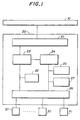
- FIG. 1 is a block diagram illustrating a basic principle of the present invention.
- FIG. 2 is a block diagram of two I/O controllers sharing a host unit and a plurality of logical devices.
- FIG. 3 is a block diagram of an embodiment of the I/O controllers of the present invention.
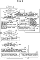
- FIG. 4 is a flow chart illustrating an operation of the first embodiment of the present invention.
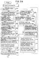
- FIGs. 5A and 5B are flow charts illustrating a second embodiment of the present invention.
- an I/O controller 20 comprises a host unit interface controller 21, a checking means 22, a controlling means 23, a decision means 24, a preventive maintenance information storage register 25, a subordinate unit interface controller 26, and a patrol timer register 27.
- the host unit interface controller 21 receives commands issued from a host unit 10.
- the subordinate unit interface controller 26 is connected to a plurality of I/O units 30 and one spare I/O unit 31.
- the checking means 22 reads data and error-detecting code concurrently from the I/O units 30, and performs error detection by using the data and error detection codes thus read, and checks for normality of data in the I/O units 30.
- the controlling means 23 selects the I/O units 30, when the result of the checking performed by the checking means 22 shows that all the data read from the I/O units are normal, and controls the operation of the I/O controller 30 according to the command from the host unit.
- the spare I/O unit 31 is not used in this case.
- the subordinate unit interface controller 26 restores all the data written in I/O units where an abnormality was found, from the data and error-detecting code read from the normal I/O units other than the I/O units where an abnormality was found, and writes the restored data into the spare I/O unit 31. Accordingly, the spare I/O unit is used as the current I/O unit in place of the I/O unit where an abnormality was found.
- the decision means 24 selects I/O units or the spare I/O unit via the subordinate unit interface controller 26, at a time interval not in use for an operation when the controlling means 23 is not processing commands input from the host unit 10 via the host unit interface controller 21, and decides whether the selected I/O units 30 or the spare I/O unit 31 operates normally.
- the decision means 24 gives a decision of abnormality
- the information about that abnormality is stored in the preventive maintenance information storage register, in order to submit it to the host unit as preventive maintenance information.
- the time interval not in use for an operation at which the decision means 24 should give a decision is determined from the count of the patrol timer register 27.
- the aforementioned decision means 24 gives decision of abnormality when the signals sent from the spare I/O unit 31 indicates a hard error when a write operation of data or a seek operation is completed.
- the decision means 24 also gives a decision of abnormality when the means reads the data in the spare I/O unit 31 and the data thus read is found to contain a read error.
- abnormality in the spare I/O unit 31 can be detected even when the spare I/O unit 31 is not in use, since a time interval not in use for an operation is used. Moreover, since preventive maintenance information is submitted to the host unit from the preventive maintenance information storage register 25, when the spare I/O 31 unit is found to contain abnormality, the host unit 10 is capable of identifying a hard error or a read error in the spare I/O unit 31 itself, based on that preventive maintenance information.
- the decision means 24 gives a decision of abnormality when a hard error signal is input from the I/O units 30, after carrying out a seek operation in the I/O units 31.
- each of the logical devices 40 0 - 40 N comprises a plurality of I/O units 30 and one spare I/O unit 31.
- each of the I/O controllers 20 1 and 20 2 it is possible for each of the I/O controllers 20 1 and 20 2 to select and control different logical devices at a given moment, based on the command from the host unit 10.
- an array-type magnetic disk controller 60 corresponds to the aforementioned I/O controller 20.
- the array-type magnetic disk controller 60 comprises a channel interface controller 61 that corresponds to the host unit interface controller 21, an operation controller 62a, a decision controller 62b, a subordinate unit interface controller 63, which corresponds to the subordinate unit interface controller 26, a preventive maintenance information storage register 64, a patrol timer register 65, and a synchronous rotation controller ler 66.
- the operation controller 62a is a circuit constituting the aforementioned checking means 22, the controlling means 23, whereas the interpretation controller 62b is a circuit constituting the decision means 24. Both comprise a processor 621, a controlled storage 622, a system reset timer register 623, a timer register 624 for monitoring the operating time, a seek address register 625, a logical device address register 626, an error detecting flag register 627, and a data transfer controller 628.
- the processor 621 controls the whole array-type magnetic disk controller, which is of a microprogrammable type.
- the controlled storage 622 stores the instruction code for the processor 621 and is used as a table for controlling a firmware.
- the data transfer controller 628 controls the data transfer between the channel interface controller 61 and the subordinate unit interface controller 63. It also generates the parity of the transferred data and transfers it to the subordinate unit interface controller 653.
- the subordinate unit interface controller 63 comprises disk controllers #0 - #9 shown as 630 - 639.
- the channel interface controller 61 comprises control registers and performs bidirectional data communication with the host unit 50.
- the host unit 50 is comprised of CPUs (central processing units).
- the synchronous rotation controller 66 puts under synchronous control magnetic disks in the ten magnetic disk drives belonging to logical devices 70 0 - 70 N described later.
- Each of the disk controllers 630 - 639 is connected to N + 1 sets of logical devices 70 0 -70 N .
- the logical devices 70 0 - 70 N are all of the same configuration, and consist of ten magnetic disk drives 700 - 709. Of these ten, the magnetic drives 700 - 707 are data disk drives with data already written in the magnetic disks, and are configured in such a way that data can be written and read at will.
- a magnetic disk drive 708 is a parity disk drive where the parity bit of the data written in the data disk drives 700 - 707 is written in a read-write enabled magnetic disk (hereinafter called a parity disk).
- a magnetic disk drive 709 is a spare disk drive and neither data nor parity is written initially in a read-write enabled magnetic disk (hereinafter called a spare disk).
- a spare disk Of the logical devices 70 0 - 70 N , only one logical device is controlled by the array-type magnetic disk controller 60 at a given moment.
- the array-type magnetic disk controllers 60 shown in FIG. 3 are provided as a pair and in parallel as shown in FIG. 2, and are connected in such a way that they share the host unit 50 and are capable of controlling, independently of each other, the logical devices 70 0 - 70 N respectively.
- the array-type magnetic controller 60 in this configuration, is characterized in that a higher speed of data transfer is attained compared with the configuration where one magnetic disk drive is used, because data defined by the command from the host unit 50 are written in and read from the data disk drives 700 - 707, in a block of 8 bytes simultaneously, while at the same time the parity of those data are written in and read from the parity disk drive 708.
- the controller in this configuration, is characterized in that it has a great reliability, because when any of the aforementioned 9 disk drives 700 - 708 is found to contain abnormality including a read error or a hardware failure while a command from the host unit 50 is being processed, it automatically restores, in the magnetic disk subsystem, the content of the disk drive where the abnormality was found, from the data of the remaining 8 normal disk drives, and writes the restored data in the spare disk drive 709.
- the unreadable data D 2 is restored from the other data D 0 , D 1 , D 3 - D 7 and the parity P 0 , which were readable. If an abnormality occurs more frequently than specified times in the data disk drive 702, all the data written in the data disk drive 702 is written in the spare disk drive by restoring it automatically from the other 8 normal disk drives in the magnetic disk subsystem.
- the spare disk drive 709 will be used in place of the data disk drive 702.
- the processor 621 determines whether any command from the host unit 50 exists (step 81). If the host unit 50 issues a command such as a read/write command to one logical device via the array-type magnetic disk controller 60, the array-type magnetic disk controller 60 performs a read/write operation of data and parity on the 9 disk drives from 700 - to 708 simultaneously via the disk controllers 630 - 639.
- the processor checks for the presence of any command from the host unit 50 each time it processes one command, as shown in FIG. 4 (step 81).
- the processor detects a command, it determines whether the command is the one given to the logical device where an error is detected during a patrol operation (step 82). Since the decision "no" is arrived at in a normal operation, the processor processes the command from the host unit 50 (step 83) and returns to step 81.
- data consisting of 1 byte each is output to the data disk drives 700 - 707 in a parallel manner via the disk controllers 630 - 637 at the time of writing.
- the parity generated from these 8 bytes of data in the data transfer controller 628 is output to the parity disk drive 708 via the disk controller 638.
- data and parity read in the disk drives 700 - 708 is input to the data transfer controller via the disk controllers 630 - 638.
- the processor determines whether it is necessary to perform an interrupt processing with the host unit 50 (step 84). For example, it determines whether a command chain involves such interrupt processing with the host unit as the one based on the device-end notification from devices after a seek is completed.
- step 85 When an interrupt processing is found necessary, the interrupt processing is performed with the host unit 50 (step 85). When an interrupt processing is unnecessary, the patrol timer register 65 is read (step 86), is incremented (step 87), and a storage (step 88) is carried out, in a sequential manner. It is then determined whether the count of the patrol timer register 65 has exceeded the specified value (that is, has exceeded the value corresponding to the specified time) following the aforementioned increment (step 89). When the count is not found to exceed the specified value in step 89, the process returns to step 81 again.
- step 90 a patrol operation is carried out on the spare disk drive 709 (step 90). More specifically, the processor 621 generates data having specific pre-defined pattern and inputs the data to the disk controller 639 via the data transfer controller 628. Error-detecting codes are then generated according to the data having a specific pattern, and attached to the aforementioned data having a specific pattern. These data having a specific pattern and error-detecting code are written on one track of the spare disk drive 639 belonging to the logical device specified in the logical device address register 626.
- the spare disk drive 639 submits a hard error signal to the disk controller 639 when the aforementioned patrol operation (read/write operation) was not successful. And the data and error-detecting code read and output from the spare disk in a read operation, is input to the data transfer controller 628 via the disk controller 639.
- the processor 621 determines whether the patrol operation was successful, depending on the presence or absence of the aforementioned hard error signal input and a read error in the aforementioned read data (step 91). When an error is not found, the processor determines that the operation was successful, and resets the error-detecting flag that is generated in a patrol operation and resides in the controlled storage 622 (step 92).
- the processor 621 collects detailed information on the error status such as the one regarding a hard error obtained after an unsuccessful seek operation, or a read error, then stores it in the preventive maintenance information storage register (step 93), and sets the error-detecting flag generated in the patrol operation and which is stored in the controlled storage 622 (step 94).
- step 92 or step 94 completes, the process returns to step 81.
- the read and write operation of the aforementioned data having a specific pattern and error-detecting code, and the error detection continue to be carried out in such a way as shown above (step 90), on one track of the spare disk in the spare disk drive 709 belonging to each logical device, at a specific interval determined by the patrol timer register 65 (steps 86 - 89), utilizing a time interval not in use for an operation when there are no commands from the host unit 50.
- the processor 621 When a command is issued from the host unit 50 to the logical device to which the spare disk where an error was detected by the patrol operation belongs (step 81, 82), the processor 621 reads the preventive maintenance information stored in the preventive maintenance information storage register 64, and submits it to the host unit 50 via the interface controller 61, and provides the unit with information regarding the error in the spare disk drive (step 95), before returning to step 81.
- any hard error or read error is found in the spare disk drive 709 itself, it is possible to make timely repairs and exchanges as they are required due to a hard error or a read error in the spare disk drive 709 itself, for example, based on the preventive maintenance information submitted from the array-type magnetic disk controller 60.
- This makes it possible to use the spare disk drive 709 without delay when a need of replacing a disk drive, in which an abnormality occurs, with the spare disk drive 709 arises.
- This embodiment is arranged in such a way that not only the patrol operation on the spare disk drive 709 but also the patrol operation on the data disk drives 700 - 707, which are the current I/O units, and the parity disk drive 708, is carried out.
- a power-on sequence is carried out in step 101 in FIG. 5A.
- the aforementioned registers 64, 65, 623 - 627 are initialized.
- the logical devices 70 0 -70 N are powered up, and the spare disk drive 709, as well as the other disk drives 700 - 708, is powered up.
- the processor 621 determines whether there is any command from the host unit 50 (step 102).
- the host unit 50 including the central processing unit (CPU)
- issues a command such as a data read or write command to one of the logical devices, via the array-type magnetic disk controller 60
- the array-type magnetic disk controller 60 carries out the read and write operation of data and parity on the 9 magnetic, disks of the disk drives 700 - 708 simultaneously, via the disk controllers 630 - 639.
- the processor 621 checks to see whether there is any command from the host unit 50 (step 102) each time it processes one command as shown in FIG. 5A. When the processor detects a command it then determines whether the command is the one issued to the logical device where an error was detected during the patrol operation (step 10). Since the decision "no" is arrived at in a normal operation, the processor processes the command from the host unit 50 (step 104) and initializes the timer register 624 for monitoring the operating time (step 105), before returning to step 102.
- step 102 When it is determined in step 102 that there are no commands from the host unit 50, the processor determines whether such interrupt processings as CONTROL END (CU END) or DEVICE END are necessary (step 106) for the host unit 50.
- CONTROL END CU END
- DEVICE END DEVICE END
- the interrupt processing is performed for the host unit 50 (step 107).
- the patrol timer register 65 is incremented (step 106), and the system reset timer register 623 is incremented (step 109), in a sequential manner. It is then determined whether the count of the system reset timer register 623 has exceeded the specified value corresponding to ten minutes (step 110), and whether the count of the patrol timer register 65 has exceeded the specified value (that is, whether it has exceeded the value corresponding to one second, the specified time) (step 111), in a sequential manner. When the counts are not found to exceed the specified values in steps 110 and 111, the process returns to step 102 again.
- one second as specified in the aforementioned patrol timer register 65 is a selection cycle of the logical device. One second has been defined empirically for the purpose of not causing any trouble in processing commands from the host unit 50.
- step 112. It is then determined whether a patrol operation is inhibited due to the setting of hardware switches provided on a maintenance panel or due to the command from the host unit 50.
- a patrol operation is inhibited, the process returns to step 102.
- the mode in which CONTROL BUSY (Cu Busy) is returned for the command from the host unit 50 is set (step 113), the content of the logical device address register 626 for executing a patrol operation, is read (step 114), and a relevant logical device is selected (step 115).
- step 116 it is determined whether the relevant logical device is available. This is done because even when the relevant logical device is not powered, the selection of a logical device in step 115 is carried out, and the processor 621 needs to examine the status of the relevant logical device, thus checking the availability of the relevant logical device.
- the relevant logical device is available, it is determined whether the relevant logical device is busy because it is used from another system (step 117). As shown in FIG. 2, when two or more array-type magnetic disk controllers 60 are used concurrently, the logical device cannot be used if it is already used by an array-type magnetic disk controller in another system.
- step 117 When the logical device is not available (step 116) or when the logical device is used from another system (step 117), the selection of the logical device is cancelled (step 118), and the logical device address register 626 for the patrol operation is incremented and stored (step 119). That is, the selection of the logical device is abandoned, and the selection of another logical device is carried out.
- the patrol timer register 65 and the timer register 624 for monitoring the operating time are respectively initialized (step 120), then the process returns to step 102.
- step 116, 117 When the logical device is available and is not used from another system (step 116, 117), the process goes on to step 121 of FIG. 5B, and the status of the physical device (namely, the data disk drives 700 - 707, the parity disk drive 708, and the spare disk drive 709) in the logical device, is read (step 121).
- the physical device namely, the data disk drives 700 - 707, the parity disk drive 708, and the spare disk drive 709
- step 122 It is then determined whether a command is executed on the logical device within twenty seconds (step 122).
- the passage of twenty seconds is determined depending on whether the count of the timer register 624 for monitoring the operating time has reached the value (count) corresponding to twenty seconds.
- the setting of twenty seconds is an empirical one and other values can serve as well.
- the patrol operation mode is switched to the logical device mode (step 123).
- This logical device mode is the mode in which the current data disk drives 700 - 707 and the parity disk drive 708 are used.
- a seek address register 625 for the patrol operation is incremented (step 124) and, a seek operation is carried out where each head of the aforementioned logical devices (namely, disk drives 700 - 708) is moved a specified distance from the current position, to be returned to their original position (step 125).
- This seek operation is a patrol seek operation, and is performed to make sure that the head is free of dust, in view of the fact that allowing the head to stay at the same position causes dust to attach to the head, thus affecting a read and write operation adversely.
- a hard error signal is transmitted from the disk drive that failed, to the corresponding disk controller.
- the processor 621 determines the presence of an error, depending on whether this hard error signal is input or not (step 126). When an error is detected, step 138 described later is executed. When no error is detected, step 140 described later is executed.
- the patrol operation mode is switched to the physical device mode (step 128) after a check is made as to whether the spare disk drive 709 is operable (in standby status) (step 127).
- This physical device mode is the mode in which only the spare disk drive 709 is used.
- the seek address register 625 for the patrol operation is incremented (step 129), and a seek operation is carried out on the spare disk drive 709 (step 130).
- This seek operation is a seek operation which is done in advance at the time of a write operation. It is needed in the spare disk drive 709, which is included in the present embodiment, because a seek operation, where a head is moved a specified distance in advance of a read or write operation, is called for from a structural point of view. This seek operation also protects the head from dust, as does the aforementioned patrol seek operation.
- the spare disk drive 709 transmits a hard error signal to the disk controller 639.
- step 131 confirms an occurrence of error.
- a normal operation is confirmed.
- the aforementioned write operation of data having a specific pattern, and of the error-detecting code is carried out on the spare disk drive 709 (step 132).
- the spare disk drive 639 transmits a hard error signal to the disk controller 639, as in the seek operation, when the aforementioned write operation was not carried out in a normal manner, so that the processor 621 can check for an error, based on whether this hard error signal is input (step 133).
- the processor carries out a seek operation, which precedes a read operation, on the spare disk drive 134 (step 134), determines whether an error occurred from presence or absence of a hard error signal (step 135), after moving the head to the start of a track on which the aforementioned error-detecting code and data are written, and when no error is found, carries out the read operation (step 136) and regenerates the aforementioned data and error-detecting code.
- a hard error signal is provided to the disk controller 639.
- the data and error-detecting code read and output from the spare disk drive in the read operation are input into the data transfer controller 628 via the disk controller 639.
- the processor tries to determine whether any hard error signal is input or there is a read error (step 137). When no error is found, the processor 621 determines that the operation was completed in a normal manner, and resets the error-detecting flag of the error-detecting flag register 627 (step 140).
- the processor 621 collects detailed information concerning the status of such errors as a hard error where a seek is not completed in a normal manner, or a read error, stores the information in the preventive maintenance information storage register 64 (step 138), and sets the error-detecting flag of the error-detecting flag register 627 (step 139).
- step 141 Cu Busy status is cancelled (step 141)
- the selection of the current logical device is cancelled in steps 118 120 of FIG. 4A, after which the logical device address register 626 for the patrol operation is incremented so that the next logical device is specified, the patrol timer register 65 and the timer register 120 for monitoring the operating time are initialized respectively, and the process returns to step 102.
- step 129 - 137 the write and read operation of the aforementioned data having a specific pattern and error-detecting code, and an error detection continue to be carried out (steps 129 - 137), on one track of the spare disk in the spared disk drive 709 belonging to each logical device, at an interval (one second, in normal cases) specified by the patrol timer register 65 (step 111), at a time interval not in use for an operation when there is no command from the host unit 50 (step 102).
- the track of the spare disk on which the read and write operation of data are carried out when the logical device is selected after one second is not the track contiguous with the previous track, but the track a specified number of tracks away.
- the recordable side of the spare disk is divided into a plurality of zones, and an increment number in step 129 is preset in the seek address register 625 so that data is written on a representative track of each zone. This makes it possible to give a decision about the normality of the spare disk in a short time.
- the processor When a command is issued from the host unit 50 to the logical device to which the spare disk found to contain an error in a patrol operation (step 102, 103) belongs, the processor reads the preventive maintenance information stored in the preventive maintenance information storage register 64, transmits it to the host unit 50 via the channel interface controller 61, submits the error information about the spare disk drive (step 142), resets the error-detecting flag set in the error-detecting flag register 627 generated in the patrol operation (step 143), and returns to step 102.
- this embodiment ensures that not only when a hard error or a read error is found in the spare disk drive 709 itself, but also when a hard error is found in the current data disk drives 700 - 707 or in the parity disk drive, it is possible to make timely repairs and exchanges as they are required due to a hard error or a read error, for example, based on the preventive maintenance information submitted from the array-type magnetic disk controller 60.
- the present invention is not limited to the embodiments above.
- the patrol timer register 65 and the register 64 for storing preventive maintenance information need not be hardware.
- the alternatives are that the processor 621 executes the timer function with firmware, or stores the preventive maintenance information in the controlled storage 622.
- the I/O controller in the present invention is connected to a plurality of I/O units and one spare I/O unit, and is suitable for high-speed data transfer in that the controller controls a plurality of I/O units concurrently and performs a read and write operation of the data from the host unit, in a parallel manner. It also has a high reliability in that the preventive maintenance information about the spare I/O unit, to be used in place of one I/O unit where an abnormality occurred, is submitted to the host unit, and is suitable for application in a computer system in which high reliability is required.
Abstract
Description
- The present invention relates to an I/O controller that controls an I/O unit based on a command from a host unit, and more particularly to an I/O controller that supplies, to a host unit, preventive maintenance information about a spare I/O unit, which is used in place of an I/O unit in which an abnormality occurs, when any abnormality occurs in an I/O unit.
- Recently, the demand for high reliability in a computer system has accompanied the demand for high reliability in an I/O subsystem. This has led to the practice of providing an I/O subsystem with a spare I/O unit. In such an I/O subsystem, the spare I/O unit is not used during normal operation. It is used only when any abnormality including a read error or a hardware failure occurs elsewhere in a current I/O unit.
- Consequently, it is required to provide an I/O subsystem with a means of monitoring normality /abnormality of a spare I/O unit and of supplying such preventive maintenance information as regarding a hard error or a read error, to a host unit, in order for a spare I/O unit to carry out the performance expected of a normal spare I/O unit.
- An array-type magnetic disk controller has been in use as an I/O controller for supplying preventive maintenance information about a spare I/O unit, to be used in place of an I/O unit where an abnormality is found, to a host unit. An array-type magnetic disk controller comprises a host unit interface controller, a subordinate unit interface controller, a processor, and various registers. A plurality of data disk drives, one parity disk drive, and one spare disk drive are connected as subordinate units and are under synchronous rotation control.
- An array-type magnetic disk controller checks for data abnormality by reading data and parity, parallel from each of a plurality of data disk drives and the parity disk drive. When no abnormality is found and a normal operation is confirmed, data is transferred to a host unit unmodified.
- When any data abnormality is detected, an array-type magnetic disk drive restores correct data on the basis of data and parity which are read from a normal data disk drive, other than the one disk drive the defective data is read from, and a parity disk drive, and transfer it to the host unit.
- If, for some reason, any abnormality including a read error or a hardware failure occurs more frequently than the specified times in one of the data disk drives acting as a current I/O unit, or in a parity disk drive, all the data written in the abnormal data disk drive or the abnormal parity disk drive is automatically and instantly recovered from the other normal data disk drives and a normal parity disk drive and restored in the spare disk drive. By using the spare disk drive as a current I/O unit, in place of the abnormal disk drive, continued operation is ensured and system down time is prevented.
- However, it could happen that the presence of a hard error or a read error in a spare disk drive itself cannot be readily detected by a host unit, and the spare disk drive itself is found to contain a hard error or a read error the first time the spare disk drive is used as an I/O unit in place of the abnormal disk drive, and cannot perform the function of a spare disk drive.
- That is why a method has been in use, in an equipment comprising a main system consisting of a plurality of units and a spare unit for backing up the units of the main system, wherein a spare unit is monitored by providing a spare unit with the same input signal as the one given to any unit of the main system, and comparing the two signals output from the spare unit and the aforementioned unit of the main system (Japanese Laid-Open Patent Application 56-72359). However, this method of monitoring necessitates continuous operation of the spare unit concurrently with the current unit in the main system. It is equivalent to having one more I/O unit to be controlled by an I/O controller, and results in increased load on the host unit.
- Another method has been in use wherein abnormalities in an I/O controller are regularly monitored according to a timetable (Japanese Laid-Open Patent Application 62-212856). This does not, however, either monitor abnormalities in a spare I/O unit or utilize a time interval not in use for an operation. Still other methods have been in use, including a method of monitoring wherein equipment provided with dual central processing units (CPU), namely the current and spare CPUs, allows a test to be carried out under a condition similar to normal operation by running a software in the spare CPU concurrently (Japanese Laid-Open Patent Application 2-93953), and a method of monitoring wherein a test is carried out at regular intervals on the spare CPU (Japanese Laid-Open Patent Application 62-90068). However, these methods of equipment monitoring having dual CPUs are not such as to monitor a spare CPU utilizing a time interval not in use for an operation.
- EP-A-320107 discloses an input/output controller comprising a plurality of I/O units, a master controller which receives an operation command from a host computer to the I/O units, checking means for checking whether data in the I/O unit are normal, based on a signal obtained by reading data and an error-detecting code concurrently from the I/O unit. When the data are not normal, one possibility is that data may be restored with the system remaining on-line. In this case, data are restored in the periods when the host computer makes no demands.
- The present invention was developed in view of the above considerations. The object of the present invention is to provide an I/O controller for monitoring the status of a spare I/O unit and/or a current I/O unit.
- Another object of the present invention is to provide an I/O controller designed for monitoring the status of a spare I/O unit and/or a current I/O unit, during a time interval not in use for an operation when no command from a host unit is being processed.
- According to the invention there is provided an input/output controller for connection to a host unit on the one hand and to a logical storage device including a first storage device storing an error correcting code such as a parity code, a second, spare, storage device and a plurality of data storage devices on the other hand, comprising an operation controller controlling a read operation on the storage devices, which controls the data storage devices and the first storage device if these storage devices are normal, not containing a hard error, a read error or both, and controls the remaining data storage devices, the first storage device and the second, spare storage device in the event that one of the data or first storage devices contain a hard error, a read error or both, characterized by means for instructing a seek operation on the storage devices if the operation controller is not processing a command input from the host unit.
- The present invention makes it possible for a host unit to monitor a hard error and a read error in an I/O unit or a spare I/O unit as part of a normal operation. This allows repairing or exchanging any abnormal I/O unit during a normal operation, and putting a spare I/O unit into a normal operation without delay when any abnormality including a read error or a hardware failure occurs in a current I/O unit so that the spare I/O unit is used for the first time by the host unit.
- The present invention uses a plurality of data disk drives and one parity disk drive as the aforementioned I/O units, uses one spare disk drive as the aforementioned spare I/O unit, comprises a synchronous rotation controller that puts these disk drives under synchronous rotation control , and comprises the aforementioned controlling means, checking means, decision means, a subordinate unit interface controller, and a channel interface controller. By using the present invention, it is possible to detect an abnormality in a spare disk drive using an array-type magnetic disk drive without producing increased load on the host unit because an abnormality of a spare disk drive can be detected at a time interval not in use for an operation, when no command from a host unit is being processed.
- The present invention may comprise a patrol timer register that counts a time interval not in use for an operation, and gives a decision about abnormality in a spare I/O unit or a spare I/O disk drive after the count of the timer register has reached a specified value. This results in an accurate counting of a time interval not in use for an operation.
- Moreover, in the aforementioned array-type magnetic disk controller of the present invention, the spare disk drive is powered by a power supplying means even when it is not in use, thus maintaining the spare I/O disk drive always ready, and allowing the decision on the spare disk drive.
- FIG. 1 is a block diagram illustrating a basic principle of the present invention.
- FIG. 2 is a block diagram of two I/O controllers sharing a host unit and a plurality of logical devices.
- FIG. 3 is a block diagram of an embodiment of the I/O controllers of the present invention.
- FIG. 4 is a flow chart illustrating an operation of the first embodiment of the present invention.
- FIGs. 5A and 5B are flow charts illustrating a second embodiment of the present invention.
- In order to give a detailed description of the present invention, explanations will be given below in accordance with the figures attached. In FIG. 1, an I/
O controller 20 comprises a hostunit interface controller 21, a checking means 22, a controllingmeans 23, a decision means 24, a preventive maintenanceinformation storage register 25, a subordinateunit interface controller 26, and apatrol timer register 27. The hostunit interface controller 21 receives commands issued from ahost unit 10. The subordinateunit interface controller 26 is connected to a plurality of I/O units 30 and one spare I/O unit 31. The checking means 22 reads data and error-detecting code concurrently from the I/O units 30, and performs error detection by using the data and error detection codes thus read, and checks for normality of data in the I/O units 30. - The controlling
means 23 selects the I/O units 30, when the result of the checking performed by the checking means 22 shows that all the data read from the I/O units are normal, and controls the operation of the I/O controller 30 according to the command from the host unit. The spare I/O unit 31 is not used in this case. - On the other hand, when the result of the checking performed by the checking means 22 shows that data read from one of the plurality of I/O units are found to contain abnormality more frequently than the specified times, the subordinate
unit interface controller 26 restores all the data written in I/O units where an abnormality was found, from the data and error-detecting code read from the normal I/O units other than the I/O units where an abnormality was found, and writes the restored data into the spare I/O unit 31. Accordingly, the spare I/O unit is used as the current I/O unit in place of the I/O unit where an abnormality was found. - The decision means 24 selects I/O units or the spare I/O unit via the subordinate
unit interface controller 26, at a time interval not in use for an operation when the controllingmeans 23 is not processing commands input from thehost unit 10 via the hostunit interface controller 21, and decides whether the selected I/O units 30 or the spare I/O unit 31 operates normally. - When the decision means 24 gives a decision of abnormality, the information about that abnormality is stored in the preventive maintenance information storage register, in order to submit it to the host unit as preventive maintenance information. The time interval not in use for an operation at which the decision means 24 should give a decision is determined from the count of the
patrol timer register 27. - The aforementioned decision means 24 gives decision of abnormality when the signals sent from the spare I/
O unit 31 indicates a hard error when a write operation of data or a seek operation is completed. The decision means 24 also gives a decision of abnormality when the means reads the data in the spare I/O unit 31 and the data thus read is found to contain a read error. - With the use of an I/
O controller 20 with such a configuration, abnormality in the spare I/O unit 31 can be detected even when the spare I/O unit 31 is not in use, since a time interval not in use for an operation is used. Moreover, since preventive maintenance information is submitted to the host unit from the preventive maintenanceinformation storage register 25, when the spare I/O 31 unit is found to contain abnormality, thehost unit 10 is capable of identifying a hard error or a read error in the spare I/O unit 31 itself, based on that preventive maintenance information. - Moreover, with the use of the I/
O controller 20, abnormality not only in the spare I/O unit 31 but also in the I/O units 30 can be detected. In the latter case, the decision means 24 gives a decision of abnormality when a hard error signal is input from the I/O units 30, after carrying out a seek operation in the I/O units 31. - It is recommended to provide two sets of this I/
O controller 20 shown as 201, 202 in FIG. 2, allow the two sets to share ahost unit 10 and a plurality of logical devices 400 - 40N. Each of the logical devices 400 - 40N comprises a plurality of I/O units 30 and one spare I/O unit 31. - With such a configuration, it is possible for each of the I/
O controllers host unit 10. - The FIG. 3 embodiment will be described. In FIG. 3, an array-type
magnetic disk controller 60 corresponds to the aforementioned I/O controller 20. The array-typemagnetic disk controller 60 comprises achannel interface controller 61 that corresponds to the hostunit interface controller 21, anoperation controller 62a, adecision controller 62b, a subordinate unit interface controller 63, which corresponds to the subordinateunit interface controller 26, a preventive maintenanceinformation storage register 64, a patrol timer register 65, and a synchronousrotation controller ler 66. - The
operation controller 62a is a circuit constituting the aforementioned checking means 22, the controlling means 23, whereas theinterpretation controller 62b is a circuit constituting the decision means 24. Both comprise aprocessor 621, a controlledstorage 622, a system resettimer register 623, atimer register 624 for monitoring the operating time, a seekaddress register 625, a logicaldevice address register 626, an error detectingflag register 627, and adata transfer controller 628. - The
processor 621 controls the whole array-type magnetic disk controller, which is of a microprogrammable type. The controlledstorage 622 stores the instruction code for theprocessor 621 and is used as a table for controlling a firmware. - The
data transfer controller 628 controls the data transfer between thechannel interface controller 61 and the subordinate unit interface controller 63. It also generates the parity of the transferred data and transfers it to the subordinate unit interface controller 653. - The subordinate unit interface controller 63 comprises disk controllers #0 - #9 shown as 630 - 639. The
channel interface controller 61 comprises control registers and performs bidirectional data communication with thehost unit 50. Thehost unit 50 is comprised of CPUs (central processing units). Thesynchronous rotation controller 66 puts under synchronous control magnetic disks in the ten magnetic disk drives belonging to logical devices 700 - 70N described later. - Each of the disk controllers 630 - 639 is connected to N + 1 sets of logical devices 700 -70N. The logical devices 700 - 70N are all of the same configuration, and consist of ten magnetic disk drives 700 - 709. Of these ten, the magnetic drives 700 - 707 are data disk drives with data already written in the magnetic disks, and are configured in such a way that data can be written and read at will.
- A
magnetic disk drive 708 is a parity disk drive where the parity bit of the data written in the data disk drives 700 - 707 is written in a read-write enabled magnetic disk (hereinafter called a parity disk). Amagnetic disk drive 709 is a spare disk drive and neither data nor parity is written initially in a read-write enabled magnetic disk (hereinafter called a spare disk). Of the logical devices 700 - 70N, only one logical device is controlled by the array-typemagnetic disk controller 60 at a given moment. - The array-type
magnetic disk controllers 60 shown in FIG. 3 are provided as a pair and in parallel as shown in FIG. 2, and are connected in such a way that they share thehost unit 50 and are capable of controlling, independently of each other, the logical devices 700 - 70N respectively. - The array-type
magnetic controller 60, in this configuration, is characterized in that a higher speed of data transfer is attained compared with the configuration where one magnetic disk drive is used, because data defined by the command from thehost unit 50 are written in and read from the data disk drives 700 - 707, in a block of 8 bytes simultaneously, while at the same time the parity of those data are written in and read from theparity disk drive 708. - Moreover, the controller, in this configuration, is characterized in that it has a great reliability, because when any of the aforementioned 9 disk drives 700 - 708 is found to contain abnormality including a read error or a hardware failure while a command from the
host unit 50 is being processed, it automatically restores, in the magnetic disk subsystem, the content of the disk drive where the abnormality was found, from the data of the remaining 8 normal disk drives, and writes the restored data in thespare disk drive 709. - For example, given that the data written in the 8 magnetic disks are D0 - D7, that the parity written in the parity disk in the one
parity disk drive 708 is P0, and that an abnormality occurred in the magnetic disk in data disk drive 702, then the unreadable data D2 is restored from the other data D0, D1, D3 - D7 and the parity P0, which were readable. If an abnormality occurs more frequently than specified times in the data disk drive 702, all the data written in the data disk drive 702 is written in the spare disk drive by restoring it automatically from the other 8 normal disk drives in the magnetic disk subsystem. Thespare disk drive 709 will be used in place of the data disk drive 702. - A description will be given below in each embodiment of an operation which may be carried out at the time no command from the
host unit 50 is being processed, in the I/O subsystem employing an array-typemagnetic disk controller 60 like the one described above. - First, a description of an operation in the first embodiment will be given using FIG. 4. This embodiment does not utilize the system reset
timer register 623, thetimer register 624 for monitoring the operating time, the seekaddress register 625, the logicaldevice address register 626, and the error-detectingflag register 627, and performs only the patrol operation on thespare disk drive 709. Referring to FIG. 4, theprocessor 621 determines whether any command from thehost unit 50 exists (step 81). If thehost unit 50 issues a command such as a read/write command to one logical device via the array-typemagnetic disk controller 60, the array-typemagnetic disk controller 60 performs a read/write operation of data and parity on the 9 disk drives from 700 - to 708 simultaneously via the disk controllers 630 - 639. - More specifically, the processor checks for the presence of any command from the
host unit 50 each time it processes one command, as shown in FIG. 4 (step 81). When the processor detects a command, it determines whether the command is the one given to the logical device where an error is detected during a patrol operation (step 82). Since the decision "no" is arrived at in a normal operation, the processor processes the command from the host unit 50 (step 83) and returns to step 81. - Assuming that the data contains 8 bytes, data consisting of 1 byte each is output to the data disk drives 700 - 707 in a parallel manner via the disk controllers 630 - 637 at the time of writing. The parity generated from these 8 bytes of data in the
data transfer controller 628 is output to theparity disk drive 708 via thedisk controller 638. At the time of reading, data and parity read in the disk drives 700 - 708 is input to the data transfer controller via the disk controllers 630 - 638. - On the other hand, when it was determined that there is no command from the
host unit 50, the processor then determines whether it is necessary to perform an interrupt processing with the host unit 50 (step 84). For example, it determines whether a command chain involves such interrupt processing with the host unit as the one based on the device-end notification from devices after a seek is completed. - When an interrupt processing is found necessary, the interrupt processing is performed with the host unit 50 (step 85). When an interrupt processing is unnecessary, the patrol timer register 65 is read (step 86), is incremented (step 87), and a storage (step 88) is carried out, in a sequential manner. It is then determined whether the count of the patrol timer register 65 has exceeded the specified value (that is, has exceeded the value corresponding to the specified time) following the aforementioned increment (step 89). When the count is not found to exceed the specified value in
step 89, the process returns to step 81 again. - When the count is found to exceed the specified value, the process then goes to step 90, where a patrol operation is carried out on the spare disk drive 709 (step 90). More specifically, the
processor 621 generates data having specific pre-defined pattern and inputs the data to thedisk controller 639 via thedata transfer controller 628. Error-detecting codes are then generated according to the data having a specific pattern, and attached to the aforementioned data having a specific pattern. These data having a specific pattern and error-detecting code are written on one track of thespare disk drive 639 belonging to the logical device specified in the logicaldevice address register 626. - The
spare disk drive 639 submits a hard error signal to thedisk controller 639 when the aforementioned patrol operation (read/write operation) was not successful. And the data and error-detecting code read and output from the spare disk in a read operation, is input to thedata transfer controller 628 via thedisk controller 639. Theprocessor 621 determines whether the patrol operation was successful, depending on the presence or absence of the aforementioned hard error signal input and a read error in the aforementioned read data (step 91). When an error is not found, the processor determines that the operation was successful, and resets the error-detecting flag that is generated in a patrol operation and resides in the controlled storage 622 (step 92). - On the other hand, when it is determined in
step 91 that there is an error, theprocessor 621 collects detailed information on the error status such as the one regarding a hard error obtained after an unsuccessful seek operation, or a read error, then stores it in the preventive maintenance information storage register (step 93), and sets the error-detecting flag generated in the patrol operation and which is stored in the controlled storage 622 (step 94). - When
step 92 orstep 94 completes, the process returns to step 81. - Thus, the read and write operation of the aforementioned data having a specific pattern and error-detecting code, and the error detection, continue to be carried out in such a way as shown above (step 90), on one track of the spare disk in the
spare disk drive 709 belonging to each logical device, at a specific interval determined by the patrol timer register 65 (steps 86 - 89), utilizing a time interval not in use for an operation when there are no commands from thehost unit 50. - When the aforementioned read and write operation on the first track of the logical device 70N completes, a read and write operation of the data having a specific pattern and error-detecting code, and an error detection, are then carried out on next track of the spare disk of the
spare disk drive 709 belonging to the logical device 700. The same operation is repeated thereafter. - When a command is issued from the
host unit 50 to the logical device to which the spare disk where an error was detected by the patrol operation belongs (step 81, 82), theprocessor 621 reads the preventive maintenance information stored in the preventive maintenanceinformation storage register 64, and submits it to thehost unit 50 via theinterface controller 61, and provides the unit with information regarding the error in the spare disk drive (step 95), before returning to step 81. - Thus, when any hard error or read error is found in the
spare disk drive 709 itself, it is possible to make timely repairs and exchanges as they are required due to a hard error or a read error in thespare disk drive 709 itself, for example, based on the preventive maintenance information submitted from the array-typemagnetic disk controller 60. This makes it possible to use thespare disk drive 709 without delay when a need of replacing a disk drive, in which an abnormality occurs, with thespare disk drive 709 arises. - A description will be given below of an operation in a second embodiment of the present invention, using the flow chart FIGs. 5A and 5B. This embodiment is arranged in such a way that not only the patrol operation on the
spare disk drive 709 but also the patrol operation on the data disk drives 700 - 707, which are the current I/O units, and theparity disk drive 708, is carried out. - Referring to FIG. 5A, when the array-type
magnetic disk controller 60 is powered, a power-on sequence is carried out instep 101 in FIG. 5A. In this power-on sequence, theaforementioned registers 64, 65, 623 - 627 are initialized. At the same time as the controller is powered up, the logical devices 700 -70N are powered up, and thespare disk drive 709, as well as the other disk drives 700 - 708, is powered up. - The
processor 621 then determines whether there is any command from the host unit 50 (step 102). When thehost unit 50, including the central processing unit (CPU), issues a command such as a data read or write command to one of the logical devices, via the array-typemagnetic disk controller 60, the array-typemagnetic disk controller 60 carries out the read and write operation of data and parity on the 9 magnetic, disks of the disk drives 700 - 708 simultaneously, via the disk controllers 630 - 639. - More specifically, the
processor 621 checks to see whether there is any command from the host unit 50 (step 102) each time it processes one command as shown in FIG. 5A. When the processor detects a command it then determines whether the command is the one issued to the logical device where an error was detected during the patrol operation (step 10). Since the decision "no" is arrived at in a normal operation, the processor processes the command from the host unit 50 (step 104) and initializes thetimer register 624 for monitoring the operating time (step 105), before returning to step 102. - When it is determined in step 102 that there are no commands from the
host unit 50, the processor determines whether such interrupt processings as CONTROL END (CU END) or DEVICE END are necessary (step 106) for thehost unit 50. - When an interrupt processing is found necessary, the interrupt processing is performed for the host unit 50 (step 107). When an interrupt processing is unnecessary, the patrol timer register 65 is incremented (step 106), and the system reset
timer register 623 is incremented (step 109), in a sequential manner. It is then determined whether the count of the system resettimer register 623 has exceeded the specified value corresponding to ten minutes (step 110), and whether the count of the patrol timer register 65 has exceeded the specified value (that is, whether it has exceeded the value corresponding to one second, the specified time) (step 111), in a sequential manner. When the counts are not found to exceed the specified values insteps 110 and 111, the process returns to step 102 again. As mentioned later, one second as specified in the aforementioned patrol timer register 65 is a selection cycle of the logical device. One second has been defined empirically for the purpose of not causing any trouble in processing commands from thehost unit 50. - On the other hand, when the counts are not found to exceed the specified value either in
step 110 or in 111, the process goes on to step 112. It is then determined whether a patrol operation is inhibited due to the setting of hardware switches provided on a maintenance panel or due to the command from thehost unit 50. When a patrol operation is inhibited, the process returns to step 102. In normal cases, where a patrol operation is not inhibited, the mode in which CONTROL BUSY (Cu Busy) is returned for the command from thehost unit 50, is set (step 113), the content of the logical device address register 626 for executing a patrol operation, is read (step 114), and a relevant logical device is selected (step 115). - Then it is determined whether the relevant logical device is available (step 116). This is done because even when the relevant logical device is not powered, the selection of a logical device in
step 115 is carried out, and theprocessor 621 needs to examine the status of the relevant logical device, thus checking the availability of the relevant logical device. When the relevant logical device is available, it is determined whether the relevant logical device is busy because it is used from another system (step 117). As shown in FIG. 2, when two or more array-typemagnetic disk controllers 60 are used concurrently, the logical device cannot be used if it is already used by an array-type magnetic disk controller in another system. - When the logical device is not available (step 116) or when the logical device is used from another system (step 117), the selection of the logical device is cancelled (step 118), and the logical device address register 626 for the patrol operation is incremented and stored (step 119). That is, the selection of the logical device is abandoned, and the selection of another logical device is carried out. The patrol timer register 65 and the
timer register 624 for monitoring the operating time are respectively initialized (step 120), then the process returns to step 102. - When the logical device is available and is not used from another system (
step 116, 117), the process goes on to step 121 of FIG. 5B, and the status of the physical device (namely, the data disk drives 700 - 707, theparity disk drive 708, and the spare disk drive 709) in the logical device, is read (step 121). - It is then determined whether a command is executed on the logical device within twenty seconds (step 122). The passage of twenty seconds is determined depending on whether the count of the
timer register 624 for monitoring the operating time has reached the value (count) corresponding to twenty seconds. The setting of twenty seconds is an empirical one and other values can serve as well. - When no commands are executed within twenty seconds, the patrol operation mode is switched to the logical device mode (step 123). This logical device mode is the mode in which the current data disk drives 700 - 707 and the
parity disk drive 708 are used. When this mode is activated a seek address register 625 for the patrol operation is incremented (step 124) and, a seek operation is carried out where each head of the aforementioned logical devices (namely, disk drives 700 - 708) is moved a specified distance from the current position, to be returned to their original position (step 125). This seek operation is a patrol seek operation, and is performed to make sure that the head is free of dust, in view of the fact that allowing the head to stay at the same position causes dust to attach to the head, thus affecting a read and write operation adversely. - When the aforementioned patrol seek operation is not completed in a normal manner, a hard error signal is transmitted from the disk drive that failed, to the corresponding disk controller. The
processor 621 determines the presence of an error, depending on whether this hard error signal is input or not (step 126). When an error is detected, step 138 described later is executed. When no error is detected, step 140 described later is executed. - When it is determined in
step 122 that a command was executed within twenty seconds, the patrol operation mode is switched to the physical device mode (step 128) after a check is made as to whether thespare disk drive 709 is operable (in standby status) (step 127). This physical device mode is the mode in which only thespare disk drive 709 is used. When this mode is activated, the seek address register 625 for the patrol operation is incremented (step 129), and a seek operation is carried out on the spare disk drive 709 (step 130). - This seek operation is a seek operation which is done in advance at the time of a write operation. It is needed in the
spare disk drive 709, which is included in the present embodiment, because a seek operation, where a head is moved a specified distance in advance of a read or write operation, is called for from a structural point of view. This seek operation also protects the head from dust, as does the aforementioned patrol seek operation. When this seek operation is not completed in a normal manner, thespare disk drive 709 transmits a hard error signal to thedisk controller 639. When this hard error signal is input,step 131 confirms an occurrence of error. When the hard error signal is not input, a normal operation is confirmed. - When a normal operation is confirmed, the aforementioned write operation of data having a specific pattern, and of the error-detecting code, is carried out on the spare disk drive 709 (step 132).
- The
spare disk drive 639 transmits a hard error signal to thedisk controller 639, as in the seek operation, when the aforementioned write operation was not carried out in a normal manner, so that theprocessor 621 can check for an error, based on whether this hard error signal is input (step 133). When no error is found, the processor carries out a seek operation, which precedes a read operation, on the spare disk drive 134 (step 134), determines whether an error occurred from presence or absence of a hard error signal (step 135), after moving the head to the start of a track on which the aforementioned error-detecting code and data are written, and when no error is found, carries out the read operation (step 136) and regenerates the aforementioned data and error-detecting code. - When any hard error exists at the time this read operation is completed, a hard error signal is provided to the
disk controller 639. The data and error-detecting code read and output from the spare disk drive in the read operation are input into thedata transfer controller 628 via thedisk controller 639. The processor tries to determine whether any hard error signal is input or there is a read error (step 137). When no error is found, theprocessor 621 determines that the operation was completed in a normal manner, and resets the error-detecting flag of the error-detecting flag register 627 (step 140). - When an error is found to occur in any of
steps processor 621 collects detailed information concerning the status of such errors as a hard error where a seek is not completed in a normal manner, or a read error, stores the information in the preventive maintenance information storage register 64 (step 138), and sets the error-detecting flag of the error-detecting flag register 627 (step 139). - When the process in
steps spare disk drive 709 is found incapable of accepting a patrol operation instep 127, Cu Busy status is cancelled (step 141), the selection of the current logical device is cancelled insteps 118 120 of FIG. 4A, after which the logical device address register 626 for the patrol operation is incremented so that the next logical device is specified, the patrol timer register 65 and thetimer register 120 for monitoring the operating time are initialized respectively, and the process returns to step 102. - Thereafter, the write and read operation of the aforementioned data having a specific pattern and error-detecting code, and an error detection continue to be carried out (steps 129 - 137), on one track of the spare disk in the spared
disk drive 709 belonging to each logical device, at an interval (one second, in normal cases) specified by the patrol timer register 65 (step 111), at a time interval not in use for an operation when there is no command from the host unit 50 (step 102). - When the above-mentioned read and write operation on the first track of the
spare disk drive 709 belonging to the logical device 70N is completed, such operations as a read and write operation of the aforementioned data having a specific pattern and of error-detecting code, and an error detection are carried out on the next track on the spare disk of thespare disk drive 709 belonging to the logical device 700. Thereafter, operations like those above are repeated. - The track of the spare disk on which the read and write operation of data are carried out when the logical device is selected after one second, is not the track contiguous with the previous track, but the track a specified number of tracks away. In other words, the recordable side of the spare disk is divided into a plurality of zones, and an increment number in
step 129 is preset in the seek address register 625 so that data is written on a representative track of each zone. This makes it possible to give a decision about the normality of the spare disk in a short time. - When a command is issued from the
host unit 50 to the logical device to which the spare disk found to contain an error in a patrol operation (step 102, 103) belongs, the processor reads the preventive maintenance information stored in the preventive maintenanceinformation storage register 64, transmits it to thehost unit 50 via thechannel interface controller 61, submits the error information about the spare disk drive (step 142), resets the error-detecting flag set in the error-detectingflag register 627 generated in the patrol operation (step 143), and returns to step 102. - Thus, this embodiment ensures that not only when a hard error or a read error is found in the
spare disk drive 709 itself, but also when a hard error is found in the current data disk drives 700 - 707 or in the parity disk drive, it is possible to make timely repairs and exchanges as they are required due to a hard error or a read error, for example, based on the preventive maintenance information submitted from the array-typemagnetic disk controller 60. - The present invention is not limited to the embodiments above. The patrol timer register 65 and the
register 64 for storing preventive maintenance information need not be hardware. The alternatives are that theprocessor 621 executes the timer function with firmware, or stores the preventive maintenance information in the controlledstorage 622. - As has been described, the I/O controller in the present invention is connected to a plurality of I/O units and one spare I/O unit, and is suitable for high-speed data transfer in that the controller controls a plurality of I/O units concurrently and performs a read and write operation of the data from the host unit, in a parallel manner. It also has a high reliability in that the preventive maintenance information about the spare I/O unit, to be used in place of one I/O unit where an abnormality occurred, is submitted to the host unit, and is suitable for application in a computer system in which high reliability is required.
Claims (13)
- An input/output controller (20) for connection to a host unit (10) on the one hand and to a logical storage device (30) including a first storage device storing an error correcting code such as a parity code, a second, spare, storage device (31) and a plurality of data storage devices (30) on the other hand, comprisingan operation controller (23) controlling a read operation on the storage devices (30,31) , which controls the data storage devices and the first storage device (30) if these storage devices are normal, not containing a hard error, a read error or both, and controls the remaining data storage devices (30), the first storage device (30) and the second, spare storage device (21) in the event that one of the data or first storage devices contain a hard error, a read error or both,
characterised by means for instructing a seek operation on the storage devices if the operation controller is not processing a comman input from the host unit. - An input/output controller according to claim 1 in which the operation controller (23) carries out a patrol operation on the first storage device and the data storage devices (30) if the logical device has not executed a command for a predetermined time.
- An input/output controller according to claim 2 in which the operation controller (23) carries out a test on the second, spare storage device (31) if the logical device has executed a command within said predetermined time.
- An input/output controller according to claim 3 in which the operation controller carries out said test by carrying out a seek operation on said second, spare, storage device (31) and testing the result.
- An input/output controller according to claim 4 in which, when the said seek operation on the second, spare, storage device (31) is carried out successfully, continues the test by carrying out, on said second, spare, storage device (31), a write operation, followed by a seek operation, followed by a read operation, and testing to see whether the operations have been carried out correctly.
- An input/output (I/O) controller (20) according to any preceding claim further comprising an information storage register (25) for storing information about an abnormality in one of the storage devices, and in which the operation controller (23) transmits the information in the information storage register to the host unit when a command is issued by the host to the logical storage device to which the information relates.
- An input/output controller for connection to a host unit (10) on the one hand and to a logical storage device including a first storage device (30) storing an error correcting code such as a parity code, a second, spare, storage device (31) and a plurality of data storage devices (30) on the other hand, comprisingan operation controller (23) controlling a read operation on the storage devices (30,31), which controls the data storage devices and the first storage device (30) if these storage devices are normal, not containing a hard error, a read error or both, and controls the remaining data storage devices, the first storage device (30) and the second, spare storage device (31) in the event that one of the data or first storage devices (30) contain a hard error, a read error or both,
characterised by an information storage register (25) for storing information about an abnormality in one of the storage devices, andin which the operation controller (23) transmits the information in the information storage register to the host unit when a command is issued by the host to the logical storage device to which the information relates. - An input/output controller (20) according to any preceding claim further comprising decision means (24) to determine whether or not there is an abnormality in the first, second or data storage means.
- An input/output controller according to claim 7 further comprising a patrol timer register (624) for counting the time interval not used for an operation, in which the decision means (24) determines whether or not an abnormality is present in a storage means after the count in the patrol timer register (624) reaches a specified value.
- An input/output controller (20) according to any preceding claim for connection to a plurality of logical storage devices.
- An input/output controller according to any preceding claim including a power supply means for supplying power to the first, second and data storage devices to maintain each of the storage devices in a ready status.
- An array storage device including a logical storage device includinga first physical storage device (30) storing an error detection code, a second physical storage device being a spare storage device (31), and physical data storage devices (30) storing data; andan input/output controller (20) according to any preceding claim.
- An array storage device according to claim 12 including a plurality of the said logical storage devices.
Applications Claiming Priority (4)
| Application Number | Priority Date | Filing Date | Title |
|---|---|---|---|
| JP25105390 | 1990-09-20 | ||
| JP25105390 | 1990-09-20 | ||
| JP251053/90 | 1990-09-20 | ||
| EP91916587A EP0502207B1 (en) | 1990-09-20 | 1991-09-20 | Input/output controller |
Related Parent Applications (2)
| Application Number | Title | Priority Date | Filing Date |
|---|---|---|---|
| EP91916587A Division EP0502207B1 (en) | 1990-09-20 | 1991-09-20 | Input/output controller |
| EP91916587.8 Division | 1992-04-04 |
Publications (2)
| Publication Number | Publication Date |
|---|---|
| EP0784272A1 true EP0784272A1 (en) | 1997-07-16 |
| EP0784272B1 EP0784272B1 (en) | 2000-05-24 |
Family
ID=17216921
Family Applications (2)
| Application Number | Title | Priority Date | Filing Date |
|---|---|---|---|
| EP91916587A Expired - Lifetime EP0502207B1 (en) | 1990-09-20 | 1991-09-20 | Input/output controller |
| EP97200322A Expired - Lifetime EP0784272B1 (en) | 1990-09-20 | 1991-09-20 | Input/output controller |
Family Applications Before (1)
| Application Number | Title | Priority Date | Filing Date |
|---|---|---|---|
| EP91916587A Expired - Lifetime EP0502207B1 (en) | 1990-09-20 | 1991-09-20 | Input/output controller |
Country Status (4)
| Country | Link |
|---|---|
| US (3) | US5491816A (en) |
| EP (2) | EP0502207B1 (en) |
| DE (2) | DE69127433T2 (en) |
| WO (1) | WO1992005495A1 (en) |
Families Citing this family (34)
| Publication number | Priority date | Publication date | Assignee | Title |
|---|---|---|---|---|
| JP2743606B2 (en) * | 1991-04-11 | 1998-04-22 | 三菱電機株式会社 | Array type recording device |
| JP3782840B2 (en) * | 1995-07-14 | 2006-06-07 | 株式会社ルネサステクノロジ | External storage device and memory access control method thereof |
| JP3419158B2 (en) * | 1995-07-20 | 2003-06-23 | 三菱電機株式会社 | Data processing method for numerical control drive |
| JPH09305328A (en) * | 1996-05-13 | 1997-11-28 | Fujitsu Ltd | Disk array device |
| US6327668B1 (en) * | 1998-06-30 | 2001-12-04 | Sun Microsystems, Inc. | Determinism in a multiprocessor computer system and monitor and processor therefor |
| US6574588B1 (en) * | 1998-09-23 | 2003-06-03 | Microsoft Corporation | Solid-state memory device that emulates a known storage device |
| US6728905B1 (en) * | 2000-03-03 | 2004-04-27 | International Business Machines Corporation | Apparatus and method for rebuilding a logical device in a cluster computer system |
| US6851005B1 (en) * | 2000-03-03 | 2005-02-01 | International Business Machines Corporation | Apparatus and method for implementing raid devices in a cluster computer system |
| US6886114B2 (en) * | 2002-01-03 | 2005-04-26 | Hewlett-Packard Development Company, L.P. | Multiple device error management |
| KR100438434B1 (en) * | 2002-06-18 | 2004-07-03 | 삼성전자주식회사 | Apparatus for controlling power and signal in electronic terminal with controller and dependent part |
| SE0301901L (en) * | 2003-06-26 | 2004-12-27 | Abb Research Ltd | Method for diagnosing equipment status |
| US20050046430A1 (en) * | 2003-09-03 | 2005-03-03 | Jouko Kinnunen | RF testing method and arrangement |
| JP4493321B2 (en) * | 2003-11-19 | 2010-06-30 | 株式会社日立製作所 | Disk array device and data saving method |
| JP2005157622A (en) * | 2003-11-25 | 2005-06-16 | Hitachi Ltd | Disk array device for idle seek |
| JP4487756B2 (en) * | 2004-12-16 | 2010-06-23 | 日本電気株式会社 | Computer system and system monitoring program |
| EP1698980A1 (en) * | 2005-03-04 | 2006-09-06 | Galileo Avionica S.p.A. | A method for managing data exchange in the avionic system of an aircraft |
| US8291161B2 (en) * | 2005-10-07 | 2012-10-16 | Agere Systems Llc | Parity rotation in storage-device array |
| US7769948B2 (en) * | 2005-10-07 | 2010-08-03 | Agere Systems Inc. | Virtual profiles for storage-device array encoding/decoding |
| JP4786312B2 (en) * | 2005-11-22 | 2011-10-05 | 株式会社日立製作所 | Storage controller and error information management method for storage controller |
| JP4369467B2 (en) * | 2006-12-12 | 2009-11-18 | 富士通株式会社 | Data relay apparatus, storage apparatus, and data relay method |
| JP5022062B2 (en) * | 2007-03-01 | 2012-09-12 | 株式会社日立製作所 | Pool I / O device operation check method and computer system |
| US8707076B2 (en) | 2007-04-18 | 2014-04-22 | Dell Products L.P. | System and method for power management of storage resources |
| JP4475598B2 (en) * | 2007-06-26 | 2010-06-09 | 株式会社日立製作所 | Storage system and storage system control method |
| US7861036B2 (en) * | 2007-09-18 | 2010-12-28 | Agere Systems Inc. | Double degraded array protection in an integrated network attached storage device |
| US8001417B2 (en) * | 2007-12-30 | 2011-08-16 | Agere Systems Inc. | Method and apparatus for repairing uncorrectable drive errors in an integrated network attached storage device |
| US8347251B2 (en) * | 2007-12-31 | 2013-01-01 | Sandisk Corporation | Integrated circuit and manufacturing process facilitating selective configuration for electromagnetic compatibility |
| US9122772B2 (en) * | 2009-05-18 | 2015-09-01 | Siemens Aktiengesellschaft | Method for analyzing message archives and corresponding computer program |
| US8356215B2 (en) * | 2010-01-19 | 2013-01-15 | Kingtiger Technology (Canada) Inc. | Testing apparatus and method for analyzing a memory module operating within an application system |
| US8780478B1 (en) * | 2012-09-26 | 2014-07-15 | Western Digital Technologies, Inc. | Grease wear leveling for a disk drive |
| JP6056417B2 (en) * | 2012-11-27 | 2017-01-11 | 富士通株式会社 | Control system, control system abnormality diagnosis method, and control system abnormality diagnosis program |
| JP5958353B2 (en) | 2013-01-15 | 2016-07-27 | 富士通株式会社 | Storage device, sweep operation control method, and sweep operation control program |
| US9208808B1 (en) | 2014-04-22 | 2015-12-08 | Western Digital Technologies, Inc. | Electronic system with unload management mechanism and method of operation thereof |
| US20160018995A1 (en) * | 2014-07-17 | 2016-01-21 | Lsi Corporation | Raid system for processing i/o requests utilizing xor commands |
| US10303536B2 (en) * | 2015-10-28 | 2019-05-28 | Via Technologies, Inc. | Non-volatile memory device and control method thereof |
Citations (4)
| Publication number | Priority date | Publication date | Assignee | Title |
|---|---|---|---|---|
| US4092732A (en) * | 1977-05-31 | 1978-05-30 | International Business Machines Corporation | System for recovering data stored in failed memory unit |
| WO1989000313A1 (en) * | 1987-07-01 | 1989-01-12 | Unisys Corporation | Fast-tag transfer improvement |
| US4862411A (en) * | 1987-02-26 | 1989-08-29 | International Business Machines Corporation | Multiple copy data mechanism on synchronous disk drives |
| US4942579A (en) * | 1987-06-02 | 1990-07-17 | Cab-Tek, Inc. | High-speed, high-capacity, fault-tolerant error-correcting storage system |
Family Cites Families (23)
| Publication number | Priority date | Publication date | Assignee | Title |
|---|---|---|---|---|
| JPS5672359A (en) * | 1979-11-17 | 1981-06-16 | Fujitsu Ltd | Supervising system for spare unit |
| JPS605023A (en) * | 1983-06-22 | 1985-01-11 | Tokuyama Soda Co Ltd | Production of aqueous solution of calcium chloride |
| FR2561428B1 (en) * | 1984-03-16 | 1986-09-12 | Bull Sa | DISC MEMORY RECORDING METHOD AND DISC MEMORY SYSTEM |
| JPH0754947B2 (en) * | 1985-10-16 | 1995-06-07 | 株式会社日立製作所 | Standby system monitoring method |
| JPS62212856A (en) * | 1986-03-14 | 1987-09-18 | Nec Corp | Abnormality monitoring device |
| JPS63279318A (en) * | 1987-05-11 | 1988-11-16 | Nec Corp | Magnetic disk device |
| US5051887A (en) * | 1987-08-25 | 1991-09-24 | International Business Machines Corporation | Maintaining duplex-paired storage devices during gap processing using of a dual copy function |
| DE3728521A1 (en) * | 1987-08-26 | 1989-03-09 | Siemens Ag | ARRANGEMENT AND METHOD FOR DETECTING AND LOCALIZING ERRORAL CIRCUITS OF A MEMORY MODULE |
| US4870643A (en) * | 1987-11-06 | 1989-09-26 | Micropolis Corporation | Parallel drive array storage system |
| US5043940A (en) * | 1988-06-08 | 1991-08-27 | Eliyahou Harari | Flash EEPROM memory systems having multistate storage cells |
| US4989205A (en) * | 1988-06-28 | 1991-01-29 | Storage Technology Corporation | Disk drive memory |
| US5077736A (en) * | 1988-06-28 | 1991-12-31 | Storage Technology Corporation | Disk drive memory |
| JPH0264835A (en) * | 1988-08-31 | 1990-03-05 | Nec Eng Ltd | Prevention device of system down |
| JPH0727468B2 (en) * | 1988-09-30 | 1995-03-29 | 日本電気株式会社 | Redundant information processing device |
| FR2643993B1 (en) * | 1989-03-03 | 1991-05-17 | Bull Sa | METHOD FOR REPLACING MEMORY MODULES IN A COMPUTER SYSTEM AND COMPUTER SYSTEM FOR IMPLEMENTING THE METHOD |
| US5535328A (en) * | 1989-04-13 | 1996-07-09 | Sandisk Corporation | Non-volatile memory system card with flash erasable sectors of EEprom cells including a mechanism for substituting defective cells |
| US5134616A (en) * | 1990-02-13 | 1992-07-28 | International Business Machines Corporation | Dynamic ram with on-chip ecc and optimized bit and word redundancy |
| US5140592A (en) * | 1990-03-02 | 1992-08-18 | Sf2 Corporation | Disk array system |
| US5124987A (en) * | 1990-04-16 | 1992-06-23 | Storage Technology Corporation | Logical track write scheduling system for a parallel disk drive array data storage subsystem |
| US5210860A (en) * | 1990-07-20 | 1993-05-11 | Compaq Computer Corporation | Intelligent disk array controller |
| US5210866A (en) * | 1990-09-12 | 1993-05-11 | Storage Technology Corporation | Incremental disk backup system for a dynamically mapped data storage subsystem |
| US5313585A (en) * | 1991-12-17 | 1994-05-17 | Jeffries Kenneth L | Disk drive array with request fragmentation |
| US5313626A (en) * | 1991-12-17 | 1994-05-17 | Jones Craig S | Disk drive array with efficient background rebuilding |
-
1991
- 1991-09-20 WO PCT/JP1991/001247 patent/WO1992005495A1/en active IP Right Grant
- 1991-09-20 EP EP91916587A patent/EP0502207B1/en not_active Expired - Lifetime
- 1991-09-20 DE DE69127433T patent/DE69127433T2/en not_active Expired - Lifetime
- 1991-09-20 EP EP97200322A patent/EP0784272B1/en not_active Expired - Lifetime
- 1991-09-20 DE DE69132227T patent/DE69132227T2/en not_active Expired - Lifetime
-
1995
- 1995-01-17 US US08/373,475 patent/US5491816A/en not_active Expired - Lifetime
- 1995-09-15 US US08/530,724 patent/US5826003A/en not_active Expired - Fee Related
-
1998
- 1998-03-02 US US09/034,010 patent/US6324655B1/en not_active Expired - Fee Related
Patent Citations (4)
| Publication number | Priority date | Publication date | Assignee | Title |
|---|---|---|---|---|
| US4092732A (en) * | 1977-05-31 | 1978-05-30 | International Business Machines Corporation | System for recovering data stored in failed memory unit |
| US4862411A (en) * | 1987-02-26 | 1989-08-29 | International Business Machines Corporation | Multiple copy data mechanism on synchronous disk drives |
| US4942579A (en) * | 1987-06-02 | 1990-07-17 | Cab-Tek, Inc. | High-speed, high-capacity, fault-tolerant error-correcting storage system |
| WO1989000313A1 (en) * | 1987-07-01 | 1989-01-12 | Unisys Corporation | Fast-tag transfer improvement |
Also Published As
| Publication number | Publication date |
|---|---|
| DE69127433D1 (en) | 1997-10-02 |
| US5491816A (en) | 1996-02-13 |
| DE69127433T2 (en) | 1998-01-02 |
| US5826003A (en) | 1998-10-20 |
| US6324655B1 (en) | 2001-11-27 |
| EP0502207B1 (en) | 1997-08-27 |
| DE69132227D1 (en) | 2000-06-29 |
| EP0502207A1 (en) | 1992-09-09 |
| EP0502207A4 (en) | 1993-02-03 |
| DE69132227T2 (en) | 2000-09-28 |
| EP0784272B1 (en) | 2000-05-24 |
| WO1992005495A1 (en) | 1992-04-02 |
Similar Documents
| Publication | Publication Date | Title |
|---|---|---|
| EP0784272B1 (en) | Input/output controller | |
| US6442711B1 (en) | System and method for avoiding storage failures in a storage array system | |
| EP0772127B1 (en) | Controller failure recovery for an Input/Output device | |
| EP0467706B1 (en) | Intelligent disk array controller background surface analysis | |
| JP2548480B2 (en) | Disk device diagnostic method for array disk device | |
| US7809979B2 (en) | Storage control apparatus and method | |
| EP0547844A2 (en) | Apparatus and method for controlling background processing in a disk array device | |
| JPH08335144A (en) | External storage device | |
| JP3284963B2 (en) | Disk array control device and control method | |
| US5729552A (en) | Process control system for activating storage device | |
| US6434711B1 (en) | Disk array apparatus that avoids premature declarations of faults | |
| JPH1195933A (en) | Disk array system | |
| JP3269817B2 (en) | I / O control unit | |
| JP2644205B2 (en) | I / O controller | |
| JP2735801B2 (en) | I / O control unit | |
| JPH1027070A (en) | Data backup system | |
| JPH05257617A (en) | Magnetic disk subsystem | |
| JP2910847B2 (en) | Array type disk controller | |
| JP3095061B2 (en) | I / O controller | |
| JPH0651918A (en) | Semiconductor disk device | |
| JPH07281966A (en) | Array type storage system | |
| WO1998041915A1 (en) | Disk array subsystem | |
| JPH103361A (en) | Data backup device | |
| JP3243656B2 (en) | Disk array device | |
| JPH08147112A (en) | Error recovery device for disk array device |
Legal Events
| Date | Code | Title | Description |
|---|---|---|---|
| PUAI | Public reference made under article 153(3) epc to a published international application that has entered the european phase |
Free format text: ORIGINAL CODE: 0009012 |
|
| AC | Divisional application: reference to earlier application |
Ref document number: 502207 Country of ref document: EP |
|
| AK | Designated contracting states |
Kind code of ref document: A1 Designated state(s): DE FR GB |
|
| 17P | Request for examination filed |
Effective date: 19970902 |
|
| 17Q | First examination report despatched |
Effective date: 19980515 |
|
| GRAG | Despatch of communication of intention to grant |
Free format text: ORIGINAL CODE: EPIDOS AGRA |
|
| GRAG | Despatch of communication of intention to grant |
Free format text: ORIGINAL CODE: EPIDOS AGRA |
|
| GRAH | Despatch of communication of intention to grant a patent |
Free format text: ORIGINAL CODE: EPIDOS IGRA |
|
| GRAH | Despatch of communication of intention to grant a patent |
Free format text: ORIGINAL CODE: EPIDOS IGRA |
|
| GRAA | (expected) grant |
Free format text: ORIGINAL CODE: 0009210 |
|
| AC | Divisional application: reference to earlier application |
Ref document number: 502207 Country of ref document: EP |
|
| AK | Designated contracting states |
Kind code of ref document: B1 Designated state(s): DE FR GB |
|
| PG25 | Lapsed in a contracting state [announced via postgrant information from national office to epo] |
Ref country code: FR Free format text: LAPSE BECAUSE OF FAILURE TO SUBMIT A TRANSLATION OF THE DESCRIPTION OR TO PAY THE FEE WITHIN THE PRESCRIBED TIME-LIMIT Effective date: 20000524 |
|
| REF | Corresponds to: |
Ref document number: 69132227 Country of ref document: DE Date of ref document: 20000629 |
|
| PG25 | Lapsed in a contracting state [announced via postgrant information from national office to epo] |
Ref country code: GB Free format text: LAPSE BECAUSE OF NON-PAYMENT OF DUE FEES Effective date: 20000920 |
|
| EN | Fr: translation not filed | ||
| PLBE | No opposition filed within time limit |
Free format text: ORIGINAL CODE: 0009261 |
|
| STAA | Information on the status of an ep patent application or granted ep patent |
Free format text: STATUS: NO OPPOSITION FILED WITHIN TIME LIMIT |
|
| GBPC | Gb: european patent ceased through non-payment of renewal fee |
Effective date: 20000920 |
|
| 26N | No opposition filed | ||
| PGFP | Annual fee paid to national office [announced via postgrant information from national office to epo] |
Ref country code: DE Payment date: 20090917 Year of fee payment: 19 |
|
| REG | Reference to a national code |
Ref country code: DE Ref legal event code: R119 Ref document number: 69132227 Country of ref document: DE Effective date: 20110401 |
|
| PG25 | Lapsed in a contracting state [announced via postgrant information from national office to epo] |
Ref country code: DE Free format text: LAPSE BECAUSE OF NON-PAYMENT OF DUE FEES Effective date: 20110401 |