EP0784967B1 - Spine implant - Google Patents
Spine implant Download PDFInfo
- Publication number
- EP0784967B1 EP0784967B1 EP96115600A EP96115600A EP0784967B1 EP 0784967 B1 EP0784967 B1 EP 0784967B1 EP 96115600 A EP96115600 A EP 96115600A EP 96115600 A EP96115600 A EP 96115600A EP 0784967 B1 EP0784967 B1 EP 0784967B1
- Authority
- EP
- European Patent Office
- Prior art keywords
- implant according
- implant
- hollow body
- cutouts
- rod
- Prior art date
- Legal status (The legal status is an assumption and is not a legal conclusion. Google has not performed a legal analysis and makes no representation as to the accuracy of the status listed.)
- Expired - Lifetime
Links
Images
Classifications
-
- A—HUMAN NECESSITIES
- A61—MEDICAL OR VETERINARY SCIENCE; HYGIENE
- A61F—FILTERS IMPLANTABLE INTO BLOOD VESSELS; PROSTHESES; DEVICES PROVIDING PATENCY TO, OR PREVENTING COLLAPSING OF, TUBULAR STRUCTURES OF THE BODY, e.g. STENTS; ORTHOPAEDIC, NURSING OR CONTRACEPTIVE DEVICES; FOMENTATION; TREATMENT OR PROTECTION OF EYES OR EARS; BANDAGES, DRESSINGS OR ABSORBENT PADS; FIRST-AID KITS
- A61F2/00—Filters implantable into blood vessels; Prostheses, i.e. artificial substitutes or replacements for parts of the body; Appliances for connecting them with the body; Devices providing patency to, or preventing collapsing of, tubular structures of the body, e.g. stents
- A61F2/02—Prostheses implantable into the body
- A61F2/30—Joints
- A61F2/44—Joints for the spine, e.g. vertebrae, spinal discs
- A61F2/4455—Joints for the spine, e.g. vertebrae, spinal discs for the fusion of spinal bodies, e.g. intervertebral fusion of adjacent spinal bodies, e.g. fusion cages
- A61F2/446—Joints for the spine, e.g. vertebrae, spinal discs for the fusion of spinal bodies, e.g. intervertebral fusion of adjacent spinal bodies, e.g. fusion cages having a circular or elliptical cross-section substantially parallel to the axis of the spine, e.g. cylinders or frustocones
-
- A—HUMAN NECESSITIES
- A61—MEDICAL OR VETERINARY SCIENCE; HYGIENE
- A61B—DIAGNOSIS; SURGERY; IDENTIFICATION
- A61B17/00—Surgical instruments, devices or methods, e.g. tourniquets
- A61B17/56—Surgical instruments or methods for treatment of bones or joints; Devices specially adapted therefor
- A61B17/58—Surgical instruments or methods for treatment of bones or joints; Devices specially adapted therefor for osteosynthesis, e.g. bone plates, screws, setting implements or the like
- A61B17/68—Internal fixation devices, including fasteners and spinal fixators, even if a part thereof projects from the skin
- A61B17/70—Spinal positioners or stabilisers ; Bone stabilisers comprising fluid filler in an implant
- A61B17/7001—Screws or hooks combined with longitudinal elements which do not contact vertebrae
- A61B17/7002—Longitudinal elements, e.g. rods
-
- A—HUMAN NECESSITIES
- A61—MEDICAL OR VETERINARY SCIENCE; HYGIENE
- A61B—DIAGNOSIS; SURGERY; IDENTIFICATION
- A61B17/00—Surgical instruments, devices or methods, e.g. tourniquets
- A61B17/56—Surgical instruments or methods for treatment of bones or joints; Devices specially adapted therefor
- A61B17/58—Surgical instruments or methods for treatment of bones or joints; Devices specially adapted therefor for osteosynthesis, e.g. bone plates, screws, setting implements or the like
- A61B17/68—Internal fixation devices, including fasteners and spinal fixators, even if a part thereof projects from the skin
- A61B17/70—Spinal positioners or stabilisers ; Bone stabilisers comprising fluid filler in an implant
- A61B17/7001—Screws or hooks combined with longitudinal elements which do not contact vertebrae
- A61B17/7032—Screws or hooks with U-shaped head or back through which longitudinal rods pass
-
- A—HUMAN NECESSITIES
- A61—MEDICAL OR VETERINARY SCIENCE; HYGIENE
- A61B—DIAGNOSIS; SURGERY; IDENTIFICATION
- A61B17/00—Surgical instruments, devices or methods, e.g. tourniquets
- A61B17/56—Surgical instruments or methods for treatment of bones or joints; Devices specially adapted therefor
- A61B17/58—Surgical instruments or methods for treatment of bones or joints; Devices specially adapted therefor for osteosynthesis, e.g. bone plates, screws, setting implements or the like
- A61B17/68—Internal fixation devices, including fasteners and spinal fixators, even if a part thereof projects from the skin
- A61B17/70—Spinal positioners or stabilisers ; Bone stabilisers comprising fluid filler in an implant
- A61B17/7001—Screws or hooks combined with longitudinal elements which do not contact vertebrae
- A61B17/7002—Longitudinal elements, e.g. rods
- A61B17/7004—Longitudinal elements, e.g. rods with a cross-section which varies along its length
- A61B17/7008—Longitudinal elements, e.g. rods with a cross-section which varies along its length with parts of, or attached to, the longitudinal elements, bearing against an outside of the screw or hook heads, e.g. nuts on threaded rods
-
- A—HUMAN NECESSITIES
- A61—MEDICAL OR VETERINARY SCIENCE; HYGIENE
- A61B—DIAGNOSIS; SURGERY; IDENTIFICATION
- A61B17/00—Surgical instruments, devices or methods, e.g. tourniquets
- A61B17/56—Surgical instruments or methods for treatment of bones or joints; Devices specially adapted therefor
- A61B17/58—Surgical instruments or methods for treatment of bones or joints; Devices specially adapted therefor for osteosynthesis, e.g. bone plates, screws, setting implements or the like
- A61B17/68—Internal fixation devices, including fasteners and spinal fixators, even if a part thereof projects from the skin
- A61B17/84—Fasteners therefor or fasteners being internal fixation devices
- A61B17/86—Pins or screws or threaded wires; nuts therefor
- A61B17/8625—Shanks, i.e. parts contacting bone tissue
-
- A—HUMAN NECESSITIES
- A61—MEDICAL OR VETERINARY SCIENCE; HYGIENE
- A61B—DIAGNOSIS; SURGERY; IDENTIFICATION
- A61B17/00—Surgical instruments, devices or methods, e.g. tourniquets
- A61B17/56—Surgical instruments or methods for treatment of bones or joints; Devices specially adapted therefor
- A61B17/58—Surgical instruments or methods for treatment of bones or joints; Devices specially adapted therefor for osteosynthesis, e.g. bone plates, screws, setting implements or the like
- A61B17/68—Internal fixation devices, including fasteners and spinal fixators, even if a part thereof projects from the skin
- A61B17/84—Fasteners therefor or fasteners being internal fixation devices
- A61B17/86—Pins or screws or threaded wires; nuts therefor
- A61B17/864—Pins or screws or threaded wires; nuts therefor hollow, e.g. with socket or cannulated
-
- A—HUMAN NECESSITIES
- A61—MEDICAL OR VETERINARY SCIENCE; HYGIENE
- A61B—DIAGNOSIS; SURGERY; IDENTIFICATION
- A61B17/00—Surgical instruments, devices or methods, e.g. tourniquets
- A61B17/56—Surgical instruments or methods for treatment of bones or joints; Devices specially adapted therefor
- A61B17/58—Surgical instruments or methods for treatment of bones or joints; Devices specially adapted therefor for osteosynthesis, e.g. bone plates, screws, setting implements or the like
- A61B17/68—Internal fixation devices, including fasteners and spinal fixators, even if a part thereof projects from the skin
- A61B17/84—Fasteners therefor or fasteners being internal fixation devices
- A61B17/86—Pins or screws or threaded wires; nuts therefor
- A61B17/8665—Nuts
-
- A—HUMAN NECESSITIES
- A61—MEDICAL OR VETERINARY SCIENCE; HYGIENE
- A61F—FILTERS IMPLANTABLE INTO BLOOD VESSELS; PROSTHESES; DEVICES PROVIDING PATENCY TO, OR PREVENTING COLLAPSING OF, TUBULAR STRUCTURES OF THE BODY, e.g. STENTS; ORTHOPAEDIC, NURSING OR CONTRACEPTIVE DEVICES; FOMENTATION; TREATMENT OR PROTECTION OF EYES OR EARS; BANDAGES, DRESSINGS OR ABSORBENT PADS; FIRST-AID KITS
- A61F2/00—Filters implantable into blood vessels; Prostheses, i.e. artificial substitutes or replacements for parts of the body; Appliances for connecting them with the body; Devices providing patency to, or preventing collapsing of, tubular structures of the body, e.g. stents
- A61F2/02—Prostheses implantable into the body
- A61F2/30—Joints
- A61F2/30721—Accessories
- A61F2/30744—End caps, e.g. for closing an endoprosthetic cavity
-
- A—HUMAN NECESSITIES
- A61—MEDICAL OR VETERINARY SCIENCE; HYGIENE
- A61F—FILTERS IMPLANTABLE INTO BLOOD VESSELS; PROSTHESES; DEVICES PROVIDING PATENCY TO, OR PREVENTING COLLAPSING OF, TUBULAR STRUCTURES OF THE BODY, e.g. STENTS; ORTHOPAEDIC, NURSING OR CONTRACEPTIVE DEVICES; FOMENTATION; TREATMENT OR PROTECTION OF EYES OR EARS; BANDAGES, DRESSINGS OR ABSORBENT PADS; FIRST-AID KITS
- A61F2/00—Filters implantable into blood vessels; Prostheses, i.e. artificial substitutes or replacements for parts of the body; Appliances for connecting them with the body; Devices providing patency to, or preventing collapsing of, tubular structures of the body, e.g. stents
- A61F2/02—Prostheses implantable into the body
- A61F2/30—Joints
- A61F2/30767—Special external or bone-contacting surface, e.g. coating for improving bone ingrowth
-
- A—HUMAN NECESSITIES
- A61—MEDICAL OR VETERINARY SCIENCE; HYGIENE
- A61F—FILTERS IMPLANTABLE INTO BLOOD VESSELS; PROSTHESES; DEVICES PROVIDING PATENCY TO, OR PREVENTING COLLAPSING OF, TUBULAR STRUCTURES OF THE BODY, e.g. STENTS; ORTHOPAEDIC, NURSING OR CONTRACEPTIVE DEVICES; FOMENTATION; TREATMENT OR PROTECTION OF EYES OR EARS; BANDAGES, DRESSINGS OR ABSORBENT PADS; FIRST-AID KITS
- A61F2/00—Filters implantable into blood vessels; Prostheses, i.e. artificial substitutes or replacements for parts of the body; Appliances for connecting them with the body; Devices providing patency to, or preventing collapsing of, tubular structures of the body, e.g. stents
- A61F2/02—Prostheses implantable into the body
- A61F2/30—Joints
- A61F2/44—Joints for the spine, e.g. vertebrae, spinal discs
- A61F2/442—Intervertebral or spinal discs, e.g. resilient
-
- A—HUMAN NECESSITIES
- A61—MEDICAL OR VETERINARY SCIENCE; HYGIENE
- A61F—FILTERS IMPLANTABLE INTO BLOOD VESSELS; PROSTHESES; DEVICES PROVIDING PATENCY TO, OR PREVENTING COLLAPSING OF, TUBULAR STRUCTURES OF THE BODY, e.g. STENTS; ORTHOPAEDIC, NURSING OR CONTRACEPTIVE DEVICES; FOMENTATION; TREATMENT OR PROTECTION OF EYES OR EARS; BANDAGES, DRESSINGS OR ABSORBENT PADS; FIRST-AID KITS
- A61F2/00—Filters implantable into blood vessels; Prostheses, i.e. artificial substitutes or replacements for parts of the body; Appliances for connecting them with the body; Devices providing patency to, or preventing collapsing of, tubular structures of the body, e.g. stents
- A61F2/02—Prostheses implantable into the body
- A61F2/30—Joints
- A61F2/46—Special tools or methods for implanting or extracting artificial joints, accessories, bone grafts or substitutes, or particular adaptations therefor
- A61F2/4603—Special tools or methods for implanting or extracting artificial joints, accessories, bone grafts or substitutes, or particular adaptations therefor for insertion or extraction of endoprosthetic joints or of accessories thereof
- A61F2/4611—Special tools or methods for implanting or extracting artificial joints, accessories, bone grafts or substitutes, or particular adaptations therefor for insertion or extraction of endoprosthetic joints or of accessories thereof of spinal prostheses
-
- A—HUMAN NECESSITIES
- A61—MEDICAL OR VETERINARY SCIENCE; HYGIENE
- A61F—FILTERS IMPLANTABLE INTO BLOOD VESSELS; PROSTHESES; DEVICES PROVIDING PATENCY TO, OR PREVENTING COLLAPSING OF, TUBULAR STRUCTURES OF THE BODY, e.g. STENTS; ORTHOPAEDIC, NURSING OR CONTRACEPTIVE DEVICES; FOMENTATION; TREATMENT OR PROTECTION OF EYES OR EARS; BANDAGES, DRESSINGS OR ABSORBENT PADS; FIRST-AID KITS
- A61F2/00—Filters implantable into blood vessels; Prostheses, i.e. artificial substitutes or replacements for parts of the body; Appliances for connecting them with the body; Devices providing patency to, or preventing collapsing of, tubular structures of the body, e.g. stents
- A61F2/02—Prostheses implantable into the body
- A61F2/28—Bones
- A61F2002/2835—Bone graft implants for filling a bony defect or an endoprosthesis cavity, e.g. by synthetic material or biological material
-
- A—HUMAN NECESSITIES
- A61—MEDICAL OR VETERINARY SCIENCE; HYGIENE
- A61F—FILTERS IMPLANTABLE INTO BLOOD VESSELS; PROSTHESES; DEVICES PROVIDING PATENCY TO, OR PREVENTING COLLAPSING OF, TUBULAR STRUCTURES OF THE BODY, e.g. STENTS; ORTHOPAEDIC, NURSING OR CONTRACEPTIVE DEVICES; FOMENTATION; TREATMENT OR PROTECTION OF EYES OR EARS; BANDAGES, DRESSINGS OR ABSORBENT PADS; FIRST-AID KITS
- A61F2/00—Filters implantable into blood vessels; Prostheses, i.e. artificial substitutes or replacements for parts of the body; Appliances for connecting them with the body; Devices providing patency to, or preventing collapsing of, tubular structures of the body, e.g. stents
- A61F2/02—Prostheses implantable into the body
- A61F2/30—Joints
- A61F2002/30001—Additional features of subject-matter classified in A61F2/28, A61F2/30 and subgroups thereof
- A61F2002/30108—Shapes
- A61F2002/3011—Cross-sections or two-dimensional shapes
- A61F2002/30112—Rounded shapes, e.g. with rounded corners
- A61F2002/30113—Rounded shapes, e.g. with rounded corners circular
-
- A—HUMAN NECESSITIES
- A61—MEDICAL OR VETERINARY SCIENCE; HYGIENE
- A61F—FILTERS IMPLANTABLE INTO BLOOD VESSELS; PROSTHESES; DEVICES PROVIDING PATENCY TO, OR PREVENTING COLLAPSING OF, TUBULAR STRUCTURES OF THE BODY, e.g. STENTS; ORTHOPAEDIC, NURSING OR CONTRACEPTIVE DEVICES; FOMENTATION; TREATMENT OR PROTECTION OF EYES OR EARS; BANDAGES, DRESSINGS OR ABSORBENT PADS; FIRST-AID KITS
- A61F2/00—Filters implantable into blood vessels; Prostheses, i.e. artificial substitutes or replacements for parts of the body; Appliances for connecting them with the body; Devices providing patency to, or preventing collapsing of, tubular structures of the body, e.g. stents
- A61F2/02—Prostheses implantable into the body
- A61F2/30—Joints
- A61F2002/30001—Additional features of subject-matter classified in A61F2/28, A61F2/30 and subgroups thereof
- A61F2002/30108—Shapes
- A61F2002/3011—Cross-sections or two-dimensional shapes
- A61F2002/30138—Convex polygonal shapes
- A61F2002/30143—Convex polygonal shapes hexagonal
-
- A—HUMAN NECESSITIES
- A61—MEDICAL OR VETERINARY SCIENCE; HYGIENE
- A61F—FILTERS IMPLANTABLE INTO BLOOD VESSELS; PROSTHESES; DEVICES PROVIDING PATENCY TO, OR PREVENTING COLLAPSING OF, TUBULAR STRUCTURES OF THE BODY, e.g. STENTS; ORTHOPAEDIC, NURSING OR CONTRACEPTIVE DEVICES; FOMENTATION; TREATMENT OR PROTECTION OF EYES OR EARS; BANDAGES, DRESSINGS OR ABSORBENT PADS; FIRST-AID KITS
- A61F2/00—Filters implantable into blood vessels; Prostheses, i.e. artificial substitutes or replacements for parts of the body; Appliances for connecting them with the body; Devices providing patency to, or preventing collapsing of, tubular structures of the body, e.g. stents
- A61F2/02—Prostheses implantable into the body
- A61F2/30—Joints
- A61F2002/30001—Additional features of subject-matter classified in A61F2/28, A61F2/30 and subgroups thereof
- A61F2002/30108—Shapes
- A61F2002/30199—Three-dimensional shapes
- A61F2002/30224—Three-dimensional shapes cylindrical
- A61F2002/30235—Three-dimensional shapes cylindrical tubular, e.g. sleeves
-
- A—HUMAN NECESSITIES
- A61—MEDICAL OR VETERINARY SCIENCE; HYGIENE
- A61F—FILTERS IMPLANTABLE INTO BLOOD VESSELS; PROSTHESES; DEVICES PROVIDING PATENCY TO, OR PREVENTING COLLAPSING OF, TUBULAR STRUCTURES OF THE BODY, e.g. STENTS; ORTHOPAEDIC, NURSING OR CONTRACEPTIVE DEVICES; FOMENTATION; TREATMENT OR PROTECTION OF EYES OR EARS; BANDAGES, DRESSINGS OR ABSORBENT PADS; FIRST-AID KITS
- A61F2/00—Filters implantable into blood vessels; Prostheses, i.e. artificial substitutes or replacements for parts of the body; Appliances for connecting them with the body; Devices providing patency to, or preventing collapsing of, tubular structures of the body, e.g. stents
- A61F2/02—Prostheses implantable into the body
- A61F2/30—Joints
- A61F2002/30001—Additional features of subject-matter classified in A61F2/28, A61F2/30 and subgroups thereof
- A61F2002/30316—The prosthesis having different structural features at different locations within the same prosthesis; Connections between prosthetic parts; Special structural features of bone or joint prostheses not otherwise provided for
- A61F2002/30329—Connections or couplings between prosthetic parts, e.g. between modular parts; Connecting elements
- A61F2002/30405—Connections or couplings between prosthetic parts, e.g. between modular parts; Connecting elements made by screwing complementary threads machined on the parts themselves
-
- A—HUMAN NECESSITIES
- A61—MEDICAL OR VETERINARY SCIENCE; HYGIENE
- A61F—FILTERS IMPLANTABLE INTO BLOOD VESSELS; PROSTHESES; DEVICES PROVIDING PATENCY TO, OR PREVENTING COLLAPSING OF, TUBULAR STRUCTURES OF THE BODY, e.g. STENTS; ORTHOPAEDIC, NURSING OR CONTRACEPTIVE DEVICES; FOMENTATION; TREATMENT OR PROTECTION OF EYES OR EARS; BANDAGES, DRESSINGS OR ABSORBENT PADS; FIRST-AID KITS
- A61F2/00—Filters implantable into blood vessels; Prostheses, i.e. artificial substitutes or replacements for parts of the body; Appliances for connecting them with the body; Devices providing patency to, or preventing collapsing of, tubular structures of the body, e.g. stents
- A61F2/02—Prostheses implantable into the body
- A61F2/30—Joints
- A61F2002/30001—Additional features of subject-matter classified in A61F2/28, A61F2/30 and subgroups thereof
- A61F2002/30316—The prosthesis having different structural features at different locations within the same prosthesis; Connections between prosthetic parts; Special structural features of bone or joint prostheses not otherwise provided for
- A61F2002/30535—Special structural features of bone or joint prostheses not otherwise provided for
- A61F2002/30593—Special structural features of bone or joint prostheses not otherwise provided for hollow
-
- A—HUMAN NECESSITIES
- A61—MEDICAL OR VETERINARY SCIENCE; HYGIENE
- A61F—FILTERS IMPLANTABLE INTO BLOOD VESSELS; PROSTHESES; DEVICES PROVIDING PATENCY TO, OR PREVENTING COLLAPSING OF, TUBULAR STRUCTURES OF THE BODY, e.g. STENTS; ORTHOPAEDIC, NURSING OR CONTRACEPTIVE DEVICES; FOMENTATION; TREATMENT OR PROTECTION OF EYES OR EARS; BANDAGES, DRESSINGS OR ABSORBENT PADS; FIRST-AID KITS
- A61F2/00—Filters implantable into blood vessels; Prostheses, i.e. artificial substitutes or replacements for parts of the body; Appliances for connecting them with the body; Devices providing patency to, or preventing collapsing of, tubular structures of the body, e.g. stents
- A61F2/02—Prostheses implantable into the body
- A61F2/30—Joints
- A61F2002/30001—Additional features of subject-matter classified in A61F2/28, A61F2/30 and subgroups thereof
- A61F2002/30316—The prosthesis having different structural features at different locations within the same prosthesis; Connections between prosthetic parts; Special structural features of bone or joint prostheses not otherwise provided for
- A61F2002/30535—Special structural features of bone or joint prostheses not otherwise provided for
- A61F2002/30594—Special structural features of bone or joint prostheses not otherwise provided for slotted, e.g. radial or meridian slot ending in a polar aperture, non-polar slots, horizontal or arcuate slots
-
- A—HUMAN NECESSITIES
- A61—MEDICAL OR VETERINARY SCIENCE; HYGIENE
- A61F—FILTERS IMPLANTABLE INTO BLOOD VESSELS; PROSTHESES; DEVICES PROVIDING PATENCY TO, OR PREVENTING COLLAPSING OF, TUBULAR STRUCTURES OF THE BODY, e.g. STENTS; ORTHOPAEDIC, NURSING OR CONTRACEPTIVE DEVICES; FOMENTATION; TREATMENT OR PROTECTION OF EYES OR EARS; BANDAGES, DRESSINGS OR ABSORBENT PADS; FIRST-AID KITS
- A61F2/00—Filters implantable into blood vessels; Prostheses, i.e. artificial substitutes or replacements for parts of the body; Appliances for connecting them with the body; Devices providing patency to, or preventing collapsing of, tubular structures of the body, e.g. stents
- A61F2/02—Prostheses implantable into the body
- A61F2/30—Joints
- A61F2/30767—Special external or bone-contacting surface, e.g. coating for improving bone ingrowth
- A61F2/30771—Special external or bone-contacting surface, e.g. coating for improving bone ingrowth applied in original prostheses, e.g. holes or grooves
- A61F2002/30772—Apertures or holes, e.g. of circular cross section
- A61F2002/30777—Oblong apertures
-
- A—HUMAN NECESSITIES
- A61—MEDICAL OR VETERINARY SCIENCE; HYGIENE
- A61F—FILTERS IMPLANTABLE INTO BLOOD VESSELS; PROSTHESES; DEVICES PROVIDING PATENCY TO, OR PREVENTING COLLAPSING OF, TUBULAR STRUCTURES OF THE BODY, e.g. STENTS; ORTHOPAEDIC, NURSING OR CONTRACEPTIVE DEVICES; FOMENTATION; TREATMENT OR PROTECTION OF EYES OR EARS; BANDAGES, DRESSINGS OR ABSORBENT PADS; FIRST-AID KITS
- A61F2/00—Filters implantable into blood vessels; Prostheses, i.e. artificial substitutes or replacements for parts of the body; Appliances for connecting them with the body; Devices providing patency to, or preventing collapsing of, tubular structures of the body, e.g. stents
- A61F2/02—Prostheses implantable into the body
- A61F2/30—Joints
- A61F2/30767—Special external or bone-contacting surface, e.g. coating for improving bone ingrowth
- A61F2/30771—Special external or bone-contacting surface, e.g. coating for improving bone ingrowth applied in original prostheses, e.g. holes or grooves
- A61F2002/30841—Sharp anchoring protrusions for impaction into the bone, e.g. sharp pins, spikes
- A61F2002/30845—Sharp anchoring protrusions for impaction into the bone, e.g. sharp pins, spikes with cutting edges
-
- A—HUMAN NECESSITIES
- A61—MEDICAL OR VETERINARY SCIENCE; HYGIENE
- A61F—FILTERS IMPLANTABLE INTO BLOOD VESSELS; PROSTHESES; DEVICES PROVIDING PATENCY TO, OR PREVENTING COLLAPSING OF, TUBULAR STRUCTURES OF THE BODY, e.g. STENTS; ORTHOPAEDIC, NURSING OR CONTRACEPTIVE DEVICES; FOMENTATION; TREATMENT OR PROTECTION OF EYES OR EARS; BANDAGES, DRESSINGS OR ABSORBENT PADS; FIRST-AID KITS
- A61F2/00—Filters implantable into blood vessels; Prostheses, i.e. artificial substitutes or replacements for parts of the body; Appliances for connecting them with the body; Devices providing patency to, or preventing collapsing of, tubular structures of the body, e.g. stents
- A61F2/02—Prostheses implantable into the body
- A61F2/30—Joints
- A61F2/30767—Special external or bone-contacting surface, e.g. coating for improving bone ingrowth
- A61F2/30771—Special external or bone-contacting surface, e.g. coating for improving bone ingrowth applied in original prostheses, e.g. holes or grooves
- A61F2002/3085—Special external or bone-contacting surface, e.g. coating for improving bone ingrowth applied in original prostheses, e.g. holes or grooves with a threaded, e.g. self-tapping, bone-engaging surface, e.g. external surface
-
- A—HUMAN NECESSITIES
- A61—MEDICAL OR VETERINARY SCIENCE; HYGIENE
- A61F—FILTERS IMPLANTABLE INTO BLOOD VESSELS; PROSTHESES; DEVICES PROVIDING PATENCY TO, OR PREVENTING COLLAPSING OF, TUBULAR STRUCTURES OF THE BODY, e.g. STENTS; ORTHOPAEDIC, NURSING OR CONTRACEPTIVE DEVICES; FOMENTATION; TREATMENT OR PROTECTION OF EYES OR EARS; BANDAGES, DRESSINGS OR ABSORBENT PADS; FIRST-AID KITS
- A61F2/00—Filters implantable into blood vessels; Prostheses, i.e. artificial substitutes or replacements for parts of the body; Appliances for connecting them with the body; Devices providing patency to, or preventing collapsing of, tubular structures of the body, e.g. stents
- A61F2/02—Prostheses implantable into the body
- A61F2/30—Joints
- A61F2/44—Joints for the spine, e.g. vertebrae, spinal discs
- A61F2002/449—Joints for the spine, e.g. vertebrae, spinal discs comprising multiple spinal implants located in different intervertebral spaces or in different vertebrae
-
- A—HUMAN NECESSITIES
- A61—MEDICAL OR VETERINARY SCIENCE; HYGIENE
- A61F—FILTERS IMPLANTABLE INTO BLOOD VESSELS; PROSTHESES; DEVICES PROVIDING PATENCY TO, OR PREVENTING COLLAPSING OF, TUBULAR STRUCTURES OF THE BODY, e.g. STENTS; ORTHOPAEDIC, NURSING OR CONTRACEPTIVE DEVICES; FOMENTATION; TREATMENT OR PROTECTION OF EYES OR EARS; BANDAGES, DRESSINGS OR ABSORBENT PADS; FIRST-AID KITS
- A61F2220/00—Fixations or connections for prostheses classified in groups A61F2/00 - A61F2/26 or A61F2/82 or A61F9/00 or A61F11/00 or subgroups thereof
- A61F2220/0025—Connections or couplings between prosthetic parts, e.g. between modular parts; Connecting elements
-
- A—HUMAN NECESSITIES
- A61—MEDICAL OR VETERINARY SCIENCE; HYGIENE
- A61F—FILTERS IMPLANTABLE INTO BLOOD VESSELS; PROSTHESES; DEVICES PROVIDING PATENCY TO, OR PREVENTING COLLAPSING OF, TUBULAR STRUCTURES OF THE BODY, e.g. STENTS; ORTHOPAEDIC, NURSING OR CONTRACEPTIVE DEVICES; FOMENTATION; TREATMENT OR PROTECTION OF EYES OR EARS; BANDAGES, DRESSINGS OR ABSORBENT PADS; FIRST-AID KITS
- A61F2230/00—Geometry of prostheses classified in groups A61F2/00 - A61F2/26 or A61F2/82 or A61F9/00 or A61F11/00 or subgroups thereof
- A61F2230/0002—Two-dimensional shapes, e.g. cross-sections
- A61F2230/0004—Rounded shapes, e.g. with rounded corners
- A61F2230/0006—Rounded shapes, e.g. with rounded corners circular
-
- A—HUMAN NECESSITIES
- A61—MEDICAL OR VETERINARY SCIENCE; HYGIENE
- A61F—FILTERS IMPLANTABLE INTO BLOOD VESSELS; PROSTHESES; DEVICES PROVIDING PATENCY TO, OR PREVENTING COLLAPSING OF, TUBULAR STRUCTURES OF THE BODY, e.g. STENTS; ORTHOPAEDIC, NURSING OR CONTRACEPTIVE DEVICES; FOMENTATION; TREATMENT OR PROTECTION OF EYES OR EARS; BANDAGES, DRESSINGS OR ABSORBENT PADS; FIRST-AID KITS
- A61F2230/00—Geometry of prostheses classified in groups A61F2/00 - A61F2/26 or A61F2/82 or A61F9/00 or A61F11/00 or subgroups thereof
- A61F2230/0002—Two-dimensional shapes, e.g. cross-sections
- A61F2230/0017—Angular shapes
-
- A—HUMAN NECESSITIES
- A61—MEDICAL OR VETERINARY SCIENCE; HYGIENE
- A61F—FILTERS IMPLANTABLE INTO BLOOD VESSELS; PROSTHESES; DEVICES PROVIDING PATENCY TO, OR PREVENTING COLLAPSING OF, TUBULAR STRUCTURES OF THE BODY, e.g. STENTS; ORTHOPAEDIC, NURSING OR CONTRACEPTIVE DEVICES; FOMENTATION; TREATMENT OR PROTECTION OF EYES OR EARS; BANDAGES, DRESSINGS OR ABSORBENT PADS; FIRST-AID KITS
- A61F2230/00—Geometry of prostheses classified in groups A61F2/00 - A61F2/26 or A61F2/82 or A61F9/00 or A61F11/00 or subgroups thereof
- A61F2230/0063—Three-dimensional shapes
- A61F2230/0069—Three-dimensional shapes cylindrical
-
- A—HUMAN NECESSITIES
- A61—MEDICAL OR VETERINARY SCIENCE; HYGIENE
- A61F—FILTERS IMPLANTABLE INTO BLOOD VESSELS; PROSTHESES; DEVICES PROVIDING PATENCY TO, OR PREVENTING COLLAPSING OF, TUBULAR STRUCTURES OF THE BODY, e.g. STENTS; ORTHOPAEDIC, NURSING OR CONTRACEPTIVE DEVICES; FOMENTATION; TREATMENT OR PROTECTION OF EYES OR EARS; BANDAGES, DRESSINGS OR ABSORBENT PADS; FIRST-AID KITS
- A61F2310/00—Prostheses classified in A61F2/28 or A61F2/30 - A61F2/44 being constructed from or coated with a particular material
- A61F2310/00005—The prosthesis being constructed from a particular material
- A61F2310/00011—Metals or alloys
- A61F2310/00023—Titanium or titanium-based alloys, e.g. Ti-Ni alloys
Definitions
- the invention relates to a spine implant according to the preamble of claim 1.
- Intervertebral discs which are damaged generatively or traumatically or which are affected by disease can cause serious physical trouble.
- damaged or by disease affected discs an result in e.g. a reduction of the space between two adjacent vertebrae such that a pressure on the nerves extending within the spine is created and thereby great pains are caused.
- Spine curvatures of large extents can be caused or the movability of two adjacent vertebrae can be strongly limited by a series of diseases, whereby the discs are affected.
- the EP 0 307 241 B1 describes an implant for maintaining a desired space between vertebrae which is inserted in prepared grooves and which is roughened on the surface for interlocking with the grooves. Furthermore, the implant has at least one throughgoing slot for receiving bone graft material.
- the implant preferably being a square block, is pushed into the grooves by means of a tool which is securely attached to an end of the implant.
- This has the disadvantage that at first the grooves have to be formed by taking out disc and bone material, whereby a high precision is necessary with the adaptation of the groove form to the form of the implant in order to achieve an exact und secure positioning of the implant. Especially with a square block implant it is difficult and takes time to avoid a cant. Corrections during the insertion of the implant are only possible with limitation.
- WO95/26164 discloses a device for spinal fixation.
- the spinal fixation device can be used as an anchor for a multi-segment to spinal alignment means.
- the spinal fixation device interdigitates with and is connected to a spinal fusion implant.
- the spinal fusion implant has a threaded blind hole for receiving a threaded post.
- the threaded post has a threaded end and a head portion having a hole for receiving a rod therethrough.
- FR 2 710 519 discloses a spine implant according to the preamble of claim 1.
- WO96/28118 discloses a spinal fixation device stabilizing vertebrae. A hollow screw is inserted into a hole saw recess in each adjoining vertebra. The rim of the hollow screw is broken by two opposing rod fixation slots. The rod is held with the screw by a locking cap. The locking cap is threaded into the screw.
- WO96/28118 was published after the date of filing the priority application DE 296 00 879. WO96/28118 is considered as comprised in the state of the art according to Article 54(3) EPC.
- the invention has the object to provide an spine implant which is insertable easily and within relatively short time.
- the spine implant according to the invention is a hollow body having at least one throughgoing opening in a side wall for receiving bone material.
- the outer surface of the hollow body has a certain roughness in order to ensure a better hold and in connection therewith also better conditions for an ingrowth.
- the hollow body substantially has a round cross section over its entire length.
- the hollow body has preferably a circular-cylindrical shape.
- the hollow body can be open and closable with a cover.
- An advantage of such a closable end is that the hollow body can be filled with spongiose bone material and can subsequently be closed.
- the cover can be screwable onto the open end and can be formed, e.g. as hexsocket head screw or as slotted or cross-slotted screw.
- the hexsocket and the slots in the cover, respectively, can simultaneously be the means for turning the hollow body upon screwing-in the hollow body into the spine.
- the hollow body is provided with one or several pairs of symmetrically opposed cutouts passing through transversely relative to the longitudinal axis in order to receive a rod which connects several implants inserted along the spine.
- the inventive implant can also be employed as part of a device for bringing into line and stabilizing, respectively, a damaged section of the spine.
- the rod can be employed as distraction or compression rod.
- the hollow body is closed at the end with which it is inserted.
- the closed end is hemisphere-like curved in order to facilitate the inserting.
- the implant is dorsally inserted to a defect disc parallel to the surface thereof.
- the diameter of the implant is chosen so that the implant reaches into both vertebrae adjoining the disc above and below in order to allow fixation of the implant by growing to bone.
- the hollow body can also comprise a self-cutting or self-forming external thread in order that the hollow body can be inserted into the prepared bore (cored hole) by turning-in, whereby the thread provides a sufficient hold in the spine.
- the external thread is self-cutting
- several throughgoing openings are provided in the side wall of the hollow body, the openings being formed as longitudinal nuts. With the nuts cutting edges are formed, which pass bone chips created during screwing-in into the inside of the hollow body.
- the hollow body can comprise means for turning using a tool.
- the cutouts can be holes so that the rod is pushed subsequently through the implants form the side. If the hollow body is open at the dorsally located end, the cutouts can also be formed like slots extending from the edge of the open end in longitudinal direction of the hollow body. In this embodiment, the rod can be simultaneously put into all provided implants. At its ventrally located end, the slot-like cutouts can be semi-circular for adaptation to the shape of the round rod.
- a screwable cover as described above can be provided with a portion, preferably a portion of the thread shank, pressing against the rod which is put into the cutouts. It can also be provided that the rod has a thread for fixation at the implant. Nuts which engage at both sides by means of correspondingly formed portions with the holes or the slot-like cutouts fix the implants at the rod. For that, the holes or the semi-circular portions of the slot-like cutouts can be provided with a counterbore, with which collars of the fixing nuts engage.
- metal is especially suitable, preferably titanium.
- the implant can be used without fixation at a rod, whereby it preferably is closable with the described hexsocket head screw.
- the implant can be employed in connection with a rod in order to provide sufficient stabilization and above all in order to avoid too strong movements.
- Such a multi-segmental fixation is also provided for anterior distraction in case of juvenile kyphoses in order to form so-called distraction instruments.
- the invention can be helpfully applied in case of anterior epiphyseodeses in connection with juvenile scolioses.
- the device according to the invention can be employed at the anterior spine.
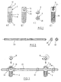
- Fig. 1a shows an implant 2 according to the invention which is formed as hollow body having an open end 4 which is closable with a cover in form of a hexsocket head screw 6 (shown in Figs. 1c and 1d).
- the hollow body of the implant 2 is circular-cylindrical and comprises a self-cutting external thread 8 which extends over the major part of the surface of the implant 2 between the open end 4 and an opposed end 10.
- Longitudinal throughgoing grooves 14 which are aligned parallel to the longitudinal axis 12 extend in the side wall of the hollow body over the area of the thread 8, whereby the longitudinal grooves form cutting edges for the thread 8.
- the closed end 10 is formed like a hemisphere.
- Fig. 1b shows the implant 2 (also without the hexsocket head screw 6) turned by 90° relative to the representation in Fig. 1a.
- two diametrically opposite slot-like cutouts 16 can be seen which extend within an area having no thread from the edge of the open end 4 parallel to the longitudinal axis 12 of the implant.
- the cutouts 16 are semi-circular at their inwardly directed end 18.
- the semi-circular portion of the cutouts is radially outside provided with a counterbore 20 for engagement with a nut 22 (comp. Fig. 2) which is used for fixation of a rod 23 put into the cutout 16 as is illustrated below in more detail.
- a hexsocket head screw 6 is shown, in the upper part of the Figure in elevational view and in the lower part in top plan view.
- the screw comprises a thread 24 (shown in Fig. 1d) and a hexsocket 26.
- Fig. 1d shows the implant 2 filled with spongial bone material 26 and with the hexsocket head screw 6 screwed on.
- the implant 2 is dorsally and in pairs inserted into a defect disc such that both implants lie side-by-side symmetrically with a certain space in the plane of the disc.
- a hole can be bored which has approximately the core diameter of the implant 2, in order to screw this in subsequently.
- the diameter of the implant is chosen so that the implant upwardly and downwardly extends over the disc into bone material of the adjacent vertebrae in order to achieve a firm anchorage of the implant.
- the implant can be screwed-in using a screwdriver-like tool, the blade of which is inserted into the cutout 16.
- the implant can also be screwed-in using a hexagonal screwdriver inserted into the hexsocket 26.
- Fig. 2 shows an above mentioned rod 23 which is insertable into the cutout 16 and with which several implants 2 can be connected with each other in order to constitute a device for bringing into line a damaged spine section.
- the rod 23 has a thread (not shown) for screwing-on nuts 22 of which one is shown in elevational view and in top plan view in Fig. 2.
- the nuts 22 have a collar 28 the form of which is adapted to the counterbore 20 to engage with the inwardly directed cutout end 18 of the implant 2.
- Fig. 3 shows a device for bringing into line a damaged spine section, the device being composed of components as shown in Fig. 1 and 2, whereby same parts are denoted by the same reference numbers.
- the device comprises two implants 2 connected by a thread rod 23 which is put into the cutouts 16 of the two implants.
- a pair of nuts 22 is provided for each implant for fixation of the rod 23, the nuts being screwed onto the rod 23 and engaging with the inwardly directed ends 18 of the cutouts 16.
- the open ends 4 of the implants and thus the cutouts can be closed. Therefore, the rod is more or less loosely held on the implants 2.
- a pre-fixation can be carried out using the hexsocket head screws 6.
- the final fixation can be done using the nuts 22. By turning only one nut, the implants can also be put under stress towards each other or away from each other (compressing - distracting).
Description
- Fig. 1
- shows an implant in elevational view and a screwable cover in elevational view and in top plan view.
- Fig. 2
- shows a rod with associated nuts for fixation at the implant of Fig. 1.
- Fig. 3
- shows the components of Figs. 1 and 2 in perspective view as they are assembled as a device for bringing in line a damaged section of the spine.
Claims (13)
- Spine implant which is formed as hollow body (2) with at least one throughgoing opening (14) in a side wall for receiving bone material (26) and the surface of the implant predominantly having a roughness, the hollow body having a round cross section over its entire length and an open end which can be closed with a cover,
characterized in thatin the side wall at the open end (4) the hollow body has at least one pair of symmetrically opposed throughgoing cutouts (16) for receiving a rod (23) which connects several implants,the hollow body has a closed end (10) being hemisphere-like curved. - Implant according to claim 1, characterized in that the hollow body substantially has a circular-cylindrical shape.
- Implant according to claim 1 or 2, characterized in that the hollow body comprises a self-cutting or self-forming external thread (8).
- Implant according to claim 3, characterized in that at an end the hollow body comprises means for turning the body using a tool.
- Implant according to one of the preceding claims, characterized in that the cover is a hexsocket head screw (6).
- Implant according to claim 5, characterized in that the cover is a slotted or cross-slotted screw.
- Implant according to one of the preceding claims, characterized in that the cutouts (16) are holes.
- Implant according to one of the preceding claims, characterized in that the cutouts (16) are slot-like and adjacent to the edge of the open end (4).
- Implant according to claim 8, characterized in that the cutouts are semi-circular at their inwardly directed end (18).
- Implant according to one of the preceding claims, characterized in that the cover (6) can be screwed so far that it presses against the rod (23) in the cutout (16).
- Implant according to one of the preceding claims, characterized in that the holes or the semi-circular portions of the cutouts (16) have a counterbore (20) in order to receive the nuts (22) having a collar (28), the nuts fixing a thread rod (23).
- Implant according to one of the preceding claims, characterized in that the throughgoing openings in the side wall are formed as longitudinal grooves (14).
- Implant according to one of the preceding claims, characterized in that it is made of metal, preferably titanium.
Applications Claiming Priority (2)
| Application Number | Priority Date | Filing Date | Title |
|---|---|---|---|
| DE29600879U DE29600879U1 (en) | 1996-01-19 | 1996-01-19 | Spinal implant |
| DE29600879U | 1996-01-19 |
Publications (3)
| Publication Number | Publication Date |
|---|---|
| EP0784967A2 EP0784967A2 (en) | 1997-07-23 |
| EP0784967A3 EP0784967A3 (en) | 1998-03-18 |
| EP0784967B1 true EP0784967B1 (en) | 2002-11-06 |
Family
ID=8018257
Family Applications (1)
| Application Number | Title | Priority Date | Filing Date |
|---|---|---|---|
| EP96115600A Expired - Lifetime EP0784967B1 (en) | 1996-01-19 | 1996-09-28 | Spine implant |
Country Status (7)
| Country | Link |
|---|---|
| US (1) | US6019760A (en) |
| EP (1) | EP0784967B1 (en) |
| JP (1) | JP3413772B2 (en) |
| AU (1) | AU715937B2 (en) |
| CA (1) | CA2194117C (en) |
| DE (2) | DE29600879U1 (en) |
| ES (1) | ES2184823T3 (en) |
Cited By (4)
| Publication number | Priority date | Publication date | Assignee | Title |
|---|---|---|---|---|
| US9216096B2 (en) | 2010-03-16 | 2015-12-22 | Pinnacle Spine Group, Llc | Intervertebral implants and related tools |
| US9380932B1 (en) | 2011-11-02 | 2016-07-05 | Pinnacle Spine Group, Llc | Retractor devices for minimally invasive access to the spine |
| US9566090B1 (en) | 2005-07-20 | 2017-02-14 | Nuvasive, Inc. | Systems and methods for treating spinal deformities |
| US10070970B2 (en) | 2013-03-14 | 2018-09-11 | Pinnacle Spine Group, Llc | Interbody implants and graft delivery systems |
Families Citing this family (54)
| Publication number | Priority date | Publication date | Assignee | Title |
|---|---|---|---|---|
| DE20004692U1 (en) * | 2000-03-14 | 2001-07-26 | Sofamor Danek Gmbh | Vertebral implant for screwing into an intervertebral space |
| US7452359B1 (en) * | 1988-06-13 | 2008-11-18 | Warsaw Orthopedic, Inc. | Apparatus for inserting spinal implants |
| US5782919A (en) | 1995-03-27 | 1998-07-21 | Sdgi Holdings, Inc. | Interbody fusion device and method for restoration of normal spinal anatomy |
| DE29616778U1 (en) | 1996-09-26 | 1998-01-29 | Howmedica Gmbh | Vertebral body placeholder |
| EP1230902A1 (en) * | 1996-11-15 | 2002-08-14 | Advanced Bio Surfaces, Inc. | Biomaterial system for in situ tissue repair |
| DE29710484U1 (en) * | 1997-06-16 | 1998-10-15 | Howmedica Gmbh | Receiving part for a holding component of a spinal implant |
| DE29823113U1 (en) * | 1998-12-28 | 2000-05-11 | Howmedica Gmbh | Femoral neck screw |
| FR2789297B1 (en) * | 1999-02-04 | 2001-05-11 | Aesculap Ag & Co Kg | REHABITABLE CONNECTING SCREW FOR THE ARTHRODESIS OF A BONE JOINT, PARTICULARLY FOR THE STABILIZATION OF TWO VERTEBRES |
| EP1639955B1 (en) * | 2000-03-28 | 2008-12-10 | Showa IKA Kohgyo Co., Ltd. | Driver tool for a spinal implant |
| CA2414168C (en) * | 2000-06-23 | 2010-02-09 | University Of Southern California | Percutaneous vertebral fusion system |
| MXPA03004216A (en) | 2000-12-08 | 2003-09-22 | Synthes Ag | Device for fixing bones, particularly vertebral bodies, in relation to one another. |
| FR2829014B1 (en) * | 2001-09-03 | 2005-04-08 | Stryker Spine | SPINAL OSTEOSYNTHESIS SYSTEM COMPRISING A SUPPORT SKATE |
| US7285121B2 (en) * | 2001-11-05 | 2007-10-23 | Warsaw Orthopedic, Inc. | Devices and methods for the correction and treatment of spinal deformities |
| US7052497B2 (en) * | 2002-08-14 | 2006-05-30 | Sdgi Holdings, Inc. | Techniques for spinal surgery and attaching constructs to vertebral elements |
| DE10246177A1 (en) * | 2002-10-02 | 2004-04-22 | Biedermann Motech Gmbh | Anchor element consists of screw with head, bone-thread section on shank and holder joining rod-shaped part to screw. with cavities in wall, and thread-free end of shank |
| DE10260222B4 (en) * | 2002-12-20 | 2008-01-03 | Biedermann Motech Gmbh | Tubular element for an implant and implant to be used in spine or bone surgery with such an element |
| US7008452B2 (en) * | 2003-06-26 | 2006-03-07 | Depuy Acromed, Inc. | Dual durometer elastomer artificial disc |
| US7297146B2 (en) | 2004-01-30 | 2007-11-20 | Warsaw Orthopedic, Inc. | Orthopedic distraction implants and techniques |
| DK1713421T3 (en) | 2004-02-13 | 2011-03-21 | Franz Jun Copf | Intervertebral implant for spinal dystrophy of the lumbar spine |
| US7766940B2 (en) * | 2004-12-30 | 2010-08-03 | Depuy Spine, Inc. | Posterior stabilization system |
| US20060084976A1 (en) | 2004-09-30 | 2006-04-20 | Depuy Spine, Inc. | Posterior stabilization systems and methods |
| US7896906B2 (en) | 2004-12-30 | 2011-03-01 | Depuy Spine, Inc. | Artificial facet joint |
| US8092496B2 (en) | 2004-09-30 | 2012-01-10 | Depuy Spine, Inc. | Methods and devices for posterior stabilization |
| US7722620B2 (en) | 2004-12-06 | 2010-05-25 | Dfine, Inc. | Bone treatment systems and methods |
| WO2006070961A2 (en) * | 2004-12-31 | 2006-07-06 | Ji-Hoon Her | Pedicle screw and device for injecting bone cement into bone |
| US20060229609A1 (en) * | 2005-03-18 | 2006-10-12 | Chao-Jan Wang | Microadjustment spinal joint fixture |
| US8100946B2 (en) | 2005-11-21 | 2012-01-24 | Synthes Usa, Llc | Polyaxial bone anchors with increased angulation |
| US20070288014A1 (en) * | 2006-06-06 | 2007-12-13 | Shadduck John H | Spine treatment devices and methods |
| US20080021465A1 (en) * | 2006-07-20 | 2008-01-24 | Shadduck John H | Spine treatment devices and methods |
| US20080077143A1 (en) * | 2006-09-25 | 2008-03-27 | Zimmer Spine, Inc. | Apparatus for connecting a longitudinal member to a bone portion |
| DE602006007475D1 (en) | 2006-11-10 | 2009-08-06 | Biedermann Motech Gmbh | Bone anchoring nail |
| US20080208260A1 (en) * | 2007-02-22 | 2008-08-28 | Csaba Truckai | Spine treatment devices and methods |
| US7967741B2 (en) * | 2007-05-01 | 2011-06-28 | Ethicon Endo-Surgery, Inc. | Endoscopic guide device |
| US9597118B2 (en) * | 2007-07-20 | 2017-03-21 | Dfine, Inc. | Bone anchor apparatus and method |
| US9439681B2 (en) | 2007-07-20 | 2016-09-13 | DePuy Synthes Products, Inc. | Polyaxial bone fixation element |
| US20090112261A1 (en) * | 2007-10-29 | 2009-04-30 | Barry Richard J | Minimally invasive spine internal fixation system |
| KR100952753B1 (en) | 2008-03-27 | 2010-04-14 | 주식회사 지에스메디칼 | A dynamic rod |
| KR101464983B1 (en) * | 2008-05-01 | 2014-11-25 | 스파인셀 프러프라이어테리 리미티드 | System methods and apparatuses for formation and insertion of tissue prothesis |
| EP2337512B1 (en) | 2008-09-12 | 2012-03-14 | Synthes GmbH | Spinal stabilizing and guiding fixation system |
| DE09793113T8 (en) | 2008-09-29 | 2013-04-25 | Synthes Gmbh | POLYAXIAL BOTTOM CHARGE SCREW AND BAR ASSEMBLY |
| US20100100135A1 (en) * | 2008-10-21 | 2010-04-22 | Phan Christopher U | Bone fixation device having an expandable anchor |
| CA2742399A1 (en) | 2008-11-03 | 2010-06-03 | Dustin M. Harvey | Uni-planar bone fixation assembly |
| US8828058B2 (en) * | 2008-11-11 | 2014-09-09 | Kspine, Inc. | Growth directed vertebral fixation system with distractible connector(s) and apical control |
| DE102009016920B4 (en) * | 2009-04-08 | 2013-03-28 | Peter Metz-Stavenhagen | Dental implant |
| CN102368967B (en) | 2009-04-15 | 2016-03-02 | 斯恩蒂斯有限公司 | For the revision connector of spinal structure |
| EP2442738B1 (en) | 2009-06-17 | 2014-04-30 | Synthes GmbH | Revision connector for spinal constructs |
| US20110066187A1 (en) * | 2009-09-11 | 2011-03-17 | Zimmer Spine, Inc. | Spinal stabilization system |
| US9220535B2 (en) * | 2010-10-26 | 2015-12-29 | Christian Röbling | Process for introducing a stabilizing element into a vertebral column |
| US10335216B2 (en) | 2011-07-15 | 2019-07-02 | Globus Medical, Inc. | Screw implants for bone fusion |
| US10925653B2 (en) | 2011-07-15 | 2021-02-23 | Globus Medical, Inc. | Screw implants for bone fusion |
| US20130018427A1 (en) * | 2011-07-15 | 2013-01-17 | Khiem Pham | Screw Implants For Bone Fusion |
| US9943340B2 (en) | 2015-02-25 | 2018-04-17 | Amendia, Inc. | Sacroiliac screw |
| US9358057B1 (en) | 2015-02-25 | 2016-06-07 | Amendia, Inc. | Sacroiliac screw |
| CN106725793A (en) * | 2017-01-10 | 2017-05-31 | 河北医科大学第三医院 | A kind of intercondylar ridge internal fixation hollow screw of detachable taking-up |
Family Cites Families (25)
| Publication number | Priority date | Publication date | Assignee | Title |
|---|---|---|---|---|
| DE2649042B1 (en) * | 1976-10-28 | 1978-01-05 | Ulrich Max Bernhard | Corrective implant for anterior derotation spondylodesis and device for adjusting the corrective implant |
| CA1146301A (en) * | 1980-06-13 | 1983-05-17 | J. David Kuntz | Intervertebral disc prosthesis |
| DE3620549A1 (en) * | 1986-06-19 | 1987-12-23 | S & G Implants Gmbh | IMPLANT FOR FIXING NEXT SPINE BONES OF THE SPINE |
| US4834757A (en) * | 1987-01-22 | 1989-05-30 | Brantigan John W | Prosthetic implant |
| US5015247A (en) * | 1988-06-13 | 1991-05-14 | Michelson Gary K | Threaded spinal implant |
| FR2642643B1 (en) * | 1989-02-09 | 1991-05-10 | Vignaud Jean Louis | SPINAL INSTRUMENTATION FOR UNIVERSAL PEDICULAR FIXATION WITH MICROMETRIC ADJUSTMENT DIAPASON SCREW |
| US5458638A (en) * | 1989-07-06 | 1995-10-17 | Spine-Tech, Inc. | Non-threaded spinal implant |
| DE9006646U1 (en) * | 1990-06-13 | 1990-08-23 | Howmedica Gmbh, 2314 Schoenkirchen, De | |
| GB9200214D0 (en) * | 1992-01-06 | 1992-02-26 | Zimmer Limited | Apparatus for use in fusion of adjacent bodies |
| ATE185062T1 (en) * | 1993-02-10 | 1999-10-15 | Sulzer Spine Tech Inc | TOOL SET FOR STABILIZING THE SPINE |
| DE4323956C1 (en) * | 1993-07-19 | 1994-10-27 | Eska Medical Gmbh & Co | Fusion dowel for vertebrae |
| FR2708461B1 (en) * | 1993-08-06 | 1995-09-29 | Advanced Technical Fabrication | Interbody implant for spine. |
| US5425772A (en) * | 1993-09-20 | 1995-06-20 | Brantigan; John W. | Prosthetic implant for intervertebral spinal fusion |
| FR2710519B1 (en) * | 1993-09-29 | 1996-01-05 | Dominique Robine | Lumbar interbody fusion cage (CH). |
| AU1290895A (en) * | 1993-11-19 | 1995-06-06 | Cross Medical Products, Inc. | Self-locking set screw for spinal fixation system |
| FR2716616A1 (en) * | 1994-02-25 | 1995-09-01 | Lenfant Jean Pierre | Pedicular bone screw e.g. for vertebral reinforcement operation |
| ES2177641T3 (en) * | 1994-03-28 | 2002-12-16 | Michelson Gary K | APPARATUS FOR SPINAL FIXATION. |
| DE9407806U1 (en) * | 1994-05-11 | 1994-07-14 | Aesculap Ag | Intervertebral implant |
| KR100231490B1 (en) * | 1994-05-23 | 1999-11-15 | . | Intervertebral fusion implant |
| AU2647795A (en) * | 1994-05-25 | 1995-12-18 | American Cyanamid Company | Vertebral fusion system with expandable anchor |
| FR2726171B1 (en) * | 1994-10-28 | 1997-01-24 | Jbs Sa | REHABITABLE CONNECTING SCREW DEVICE FOR BONE JOINT, IN PARTICULAR FOR STABILIZING AT LEAST TWO VERTEBRES |
| CN1134810A (en) * | 1995-02-17 | 1996-11-06 | 索发默达纳集团股份有限公司 | Improved interbody spinal fusion implants |
| US5591235A (en) * | 1995-03-15 | 1997-01-07 | Kuslich; Stephen D. | Spinal fixation device |
| DE29511146U1 (en) * | 1995-06-29 | 1995-11-30 | Ohst Norbert Ing | Spinal implant |
| US5766253A (en) * | 1996-01-16 | 1998-06-16 | Surgical Dynamics, Inc. | Spinal fusion device |
-
1996
- 1996-01-19 DE DE29600879U patent/DE29600879U1/en not_active Expired - Lifetime
- 1996-09-28 EP EP96115600A patent/EP0784967B1/en not_active Expired - Lifetime
- 1996-09-28 DE DE69624672T patent/DE69624672T2/en not_active Expired - Lifetime
- 1996-09-28 ES ES96115600T patent/ES2184823T3/en not_active Expired - Lifetime
- 1996-12-30 CA CA002194117A patent/CA2194117C/en not_active Expired - Lifetime
-
1997
- 1997-01-16 US US08/782,692 patent/US6019760A/en not_active Expired - Lifetime
- 1997-01-17 AU AU12211/97A patent/AU715937B2/en not_active Expired
- 1997-01-20 JP JP00740797A patent/JP3413772B2/en not_active Expired - Lifetime
Cited By (6)
| Publication number | Priority date | Publication date | Assignee | Title |
|---|---|---|---|---|
| US9566090B1 (en) | 2005-07-20 | 2017-02-14 | Nuvasive, Inc. | Systems and methods for treating spinal deformities |
| US9216096B2 (en) | 2010-03-16 | 2015-12-22 | Pinnacle Spine Group, Llc | Intervertebral implants and related tools |
| US9649203B2 (en) | 2010-03-16 | 2017-05-16 | Pinnacle Spine Group, Llc | Methods of post-filling an intervertebral implant |
| US9788973B2 (en) | 2010-03-16 | 2017-10-17 | Pinnacle Spine Group, Llc | Spinal implant |
| US9380932B1 (en) | 2011-11-02 | 2016-07-05 | Pinnacle Spine Group, Llc | Retractor devices for minimally invasive access to the spine |
| US10070970B2 (en) | 2013-03-14 | 2018-09-11 | Pinnacle Spine Group, Llc | Interbody implants and graft delivery systems |
Also Published As
| Publication number | Publication date |
|---|---|
| AU715937B2 (en) | 2000-02-10 |
| AU1221197A (en) | 1997-07-24 |
| DE29600879U1 (en) | 1996-03-28 |
| EP0784967A3 (en) | 1998-03-18 |
| JP3413772B2 (en) | 2003-06-09 |
| US6019760A (en) | 2000-02-01 |
| DE69624672D1 (en) | 2002-12-12 |
| CA2194117C (en) | 2001-08-28 |
| EP0784967A2 (en) | 1997-07-23 |
| ES2184823T3 (en) | 2003-04-16 |
| CA2194117A1 (en) | 1997-07-20 |
| DE69624672T2 (en) | 2003-03-20 |
| JPH09192149A (en) | 1997-07-29 |
Similar Documents
| Publication | Publication Date | Title |
|---|---|---|
| EP0784967B1 (en) | Spine implant | |
| US5658285A (en) | Rehabitable connecting-screw device for a bone joint, intended in particular for stabilizing at least two vertebrae | |
| US7041135B2 (en) | Interbody spinal fusion implants with single-lock for locking opposed screws | |
| US6306136B1 (en) | Implant, in particular front cervical plate | |
| US6083225A (en) | Method and instrumentation for implant insertion | |
| US5584831A (en) | Spinal fixation device and method | |
| US5702453A (en) | Adjustable vertebral body replacement | |
| AU2001296380B2 (en) | Method and apparatus for stabilizing adjacent bones | |
| US5776197A (en) | Adjustable vertebral body replacement | |
| CA2569778C (en) | Interbody spinal fusion implants | |
| US5968098A (en) | Apparatus for fusing adjacent bone structures | |
| AU2002245390B2 (en) | Apparatus for implantation into bone | |
| EP0880938B1 (en) | Instrumentation for implant insertion | |
| US8070782B2 (en) | Facet fusion implants and methods of use | |
| US20040153078A1 (en) | Anterior buttress staple | |
| GB2154296A (en) | Sacral fixation screw | |
| WO1998057601A1 (en) | Vertebral replacement implant | |
| CA2440469A1 (en) | Apparatus for implantation into bone | |
| EP1433426A1 (en) | Posterior vertebral body fastening device in the lumbar region | |
| KR100391253B1 (en) | an assembling instrument for an orthopedic surgery | |
| AU3893001A (en) | Method and instrumentation for implant insertion | |
| MXPA00002530A (en) | Fusion implant device and method of use |
Legal Events
| Date | Code | Title | Description |
|---|---|---|---|
| PUAI | Public reference made under article 153(3) epc to a published international application that has entered the european phase |
Free format text: ORIGINAL CODE: 0009012 |
|
| AK | Designated contracting states |
Kind code of ref document: A2 Designated state(s): CH DE ES FR GB IT LI NL SE |
|
| PUAL | Search report despatched |
Free format text: ORIGINAL CODE: 0009013 |
|
| AK | Designated contracting states |
Kind code of ref document: A3 Designated state(s): CH DE ES FR GB IT LI NL SE |
|
| 17P | Request for examination filed |
Effective date: 19980804 |
|
| 17Q | First examination report despatched |
Effective date: 20010315 |
|
| GRAG | Despatch of communication of intention to grant |
Free format text: ORIGINAL CODE: EPIDOS AGRA |
|
| GRAG | Despatch of communication of intention to grant |
Free format text: ORIGINAL CODE: EPIDOS AGRA |
|
| GRAH | Despatch of communication of intention to grant a patent |
Free format text: ORIGINAL CODE: EPIDOS IGRA |
|
| GRAH | Despatch of communication of intention to grant a patent |
Free format text: ORIGINAL CODE: EPIDOS IGRA |
|
| GRAA | (expected) grant |
Free format text: ORIGINAL CODE: 0009210 |
|
| RAP1 | Party data changed (applicant data changed or rights of an application transferred) |
Owner name: STRYKER TRAUMA GMBH |
|
| AK | Designated contracting states |
Kind code of ref document: B1 Designated state(s): CH DE ES FR GB IT LI NL SE |
|
| PG25 | Lapsed in a contracting state [announced via postgrant information from national office to epo] |
Ref country code: NL Free format text: LAPSE BECAUSE OF FAILURE TO SUBMIT A TRANSLATION OF THE DESCRIPTION OR TO PAY THE FEE WITHIN THE PRESCRIBED TIME-LIMIT Effective date: 20021106 |
|
| REG | Reference to a national code |
Ref country code: GB Ref legal event code: FG4D |
|
| REG | Reference to a national code |
Ref country code: CH Ref legal event code: EP |
|
| REF | Corresponds to: |
Ref document number: 69624672 Country of ref document: DE Date of ref document: 20021212 |
|
| PG25 | Lapsed in a contracting state [announced via postgrant information from national office to epo] |
Ref country code: SE Free format text: LAPSE BECAUSE OF FAILURE TO SUBMIT A TRANSLATION OF THE DESCRIPTION OR TO PAY THE FEE WITHIN THE PRESCRIBED TIME-LIMIT Effective date: 20030206 |
|
| REG | Reference to a national code |
Ref country code: CH Ref legal event code: NV Representative=s name: ISLER & PEDRAZZINI AG |
|
| ET | Fr: translation filed | ||
| NLV1 | Nl: lapsed or annulled due to failure to fulfill the requirements of art. 29p and 29m of the patents act | ||
| REG | Reference to a national code |
Ref country code: ES Ref legal event code: FG2A Ref document number: 2184823 Country of ref document: ES Kind code of ref document: T3 |
|
| PLBE | No opposition filed within time limit |
Free format text: ORIGINAL CODE: 0009261 |
|
| STAA | Information on the status of an ep patent application or granted ep patent |
Free format text: STATUS: NO OPPOSITION FILED WITHIN TIME LIMIT |
|
| 26N | No opposition filed |
Effective date: 20030807 |
|
| PGFP | Annual fee paid to national office [announced via postgrant information from national office to epo] |
Ref country code: IT Payment date: 20060930 Year of fee payment: 11 |
|
| REG | Reference to a national code |
Ref country code: CH Ref legal event code: PCAR Free format text: ISLER & PEDRAZZINI AG;POSTFACH 1772;8027 ZUERICH (CH) |
|
| PG25 | Lapsed in a contracting state [announced via postgrant information from national office to epo] |
Ref country code: IT Free format text: LAPSE BECAUSE OF NON-PAYMENT OF DUE FEES Effective date: 20070928 |
|
| REG | Reference to a national code |
Ref country code: FR Ref legal event code: PLFP Year of fee payment: 20 |
|
| PGFP | Annual fee paid to national office [announced via postgrant information from national office to epo] |
Ref country code: GB Payment date: 20150923 Year of fee payment: 20 Ref country code: CH Payment date: 20150911 Year of fee payment: 20 Ref country code: DE Payment date: 20150922 Year of fee payment: 20 Ref country code: ES Payment date: 20150810 Year of fee payment: 20 |
|
| PGFP | Annual fee paid to national office [announced via postgrant information from national office to epo] |
Ref country code: FR Payment date: 20150629 Year of fee payment: 20 |
|
| REG | Reference to a national code |
Ref country code: CH Ref legal event code: PUE Owner name: STRYKER EUROPEAN HOLDINGS VI, LLC, US Free format text: FORMER OWNER: STRYKER TRAUMA GMBH, DE Ref country code: CH Ref legal event code: PUE Owner name: STRYKER EUROPEAN HOLDINGS I, LLC, US Free format text: FORMER OWNER: STRYKER EUROPEAN HOLDINGS VI, LLC, US |
|
| REG | Reference to a national code |
Ref country code: DE Ref legal event code: R082 Ref document number: 69624672 Country of ref document: DE Representative=s name: HAUCK PATENTANWALTSPARTNERSCHAFT MBB, DE Ref country code: DE Ref legal event code: R081 Ref document number: 69624672 Country of ref document: DE Owner name: STRYKER EUROPEAN HOLDINGS I, LLC (N.D. GES. D., US Free format text: FORMER OWNER: STRYKER EUROPEAN HOLDINGS VI, LLC (N.D. GES. D. STAATES DELAWARE), KALAMAZOO, MICH., US Ref country code: DE Ref legal event code: R081 Ref document number: 69624672 Country of ref document: DE Owner name: STRYKER EUROPEAN HOLDINGS I, LLC (N.D. GES. D., US Free format text: FORMER OWNER: STRYKER TRAUMA GMBH, 24232 SCHOENKIRCHEN, DE |
|
| REG | Reference to a national code |
Ref country code: DE Ref legal event code: R071 Ref document number: 69624672 Country of ref document: DE |
|
| REG | Reference to a national code |
Ref country code: CH Ref legal event code: PL |
|
| REG | Reference to a national code |
Ref country code: GB Ref legal event code: PE20 Expiry date: 20160927 |
|
| PG25 | Lapsed in a contracting state [announced via postgrant information from national office to epo] |
Ref country code: GB Free format text: LAPSE BECAUSE OF EXPIRATION OF PROTECTION Effective date: 20160927 |
|
| REG | Reference to a national code |
Ref country code: GB Ref legal event code: 732E Free format text: REGISTERED BETWEEN 20161013 AND 20161019 |
|
| REG | Reference to a national code |
Ref country code: ES Ref legal event code: PC2A Owner name: STRYKER EUROPEAN HOLDINGS I, LLC Effective date: 20161115 |
|
| REG | Reference to a national code |
Ref country code: FR Ref legal event code: TP Owner name: STRYKER EUROPEAN HOLDINGS I, LLC, US Effective date: 20161108 |
|
| REG | Reference to a national code |
Ref country code: ES Ref legal event code: FD2A Effective date: 20170104 |
|
| PG25 | Lapsed in a contracting state [announced via postgrant information from national office to epo] |
Ref country code: ES Free format text: LAPSE BECAUSE OF EXPIRATION OF PROTECTION Effective date: 20160929 |