EP0793000A2 - Method for correcting directional surveys - Google Patents
Method for correcting directional surveys Download PDFInfo
- Publication number
- EP0793000A2 EP0793000A2 EP96303391A EP96303391A EP0793000A2 EP 0793000 A2 EP0793000 A2 EP 0793000A2 EP 96303391 A EP96303391 A EP 96303391A EP 96303391 A EP96303391 A EP 96303391A EP 0793000 A2 EP0793000 A2 EP 0793000A2
- Authority
- EP
- European Patent Office
- Prior art keywords
- magnetic field
- measurements
- magnetic
- components
- parameters
- Prior art date
- Legal status (The legal status is an assumption and is not a legal conclusion. Google has not performed a legal analysis and makes no representation as to the accuracy of the status listed.)
- Granted
Links
Images


Classifications
-
- E—FIXED CONSTRUCTIONS
- E21—EARTH DRILLING; MINING
- E21B—EARTH DRILLING, e.g. DEEP DRILLING; OBTAINING OIL, GAS, WATER, SOLUBLE OR MELTABLE MATERIALS OR A SLURRY OF MINERALS FROM WELLS
- E21B47/00—Survey of boreholes or wells
- E21B47/02—Determining slope or direction
- E21B47/022—Determining slope or direction of the borehole, e.g. using geomagnetism
Landscapes
- Physics & Mathematics (AREA)
- Life Sciences & Earth Sciences (AREA)
- Engineering & Computer Science (AREA)
- Geology (AREA)
- Mining & Mineral Resources (AREA)
- Geophysics (AREA)
- Environmental & Geological Engineering (AREA)
- Fluid Mechanics (AREA)
- General Life Sciences & Earth Sciences (AREA)
- Geochemistry & Mineralogy (AREA)
- Geophysics And Detection Of Objects (AREA)
Abstract
Description
- The present invention relates to the determination of the orientation of a borehole, using measurements of gravity and magnetic field.
- The measurements used for determining the orientation of the borehole come from survey packages taken at different levels in the borehole.
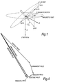
- The survey packages referred to in this invention refer to a combination of magnetometers and accelerometers which measure the earth's magnetic field vector and gravity vector respectively. These measurements can be used to determine the orientation of a survey package and hence of the equipment in which it is installed, the orientation being the azimuth ("Azi") with respect to North, the inclination ("Inc") with respect to the horizontal and the bodily rotation ("Rot") about a specified axis of the package (see Figure 1).
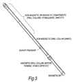
- Within the oil industry the major application of survey packages is in drilling, where it is important to monitor the direction of the borehole while being drilled. Figure 3 depicts a typical arrangement of components in a drilling assembly, where the survey package is installed in a supposedly non-magnetic environment which distances it from the magnetic components above and below. While there are many other applications and circumstances of use, this application to drilling is the one with respect to which the present invention will be described in most detail.
- When drilling, the survey package is installed in a special section of drilling pipe made from 'non-magnetic' material and known as a non-magnetic drill collar (NMDC). This environment, near the drilling bit, is subject to much shock and vibration, and to winding and unwinding of the pipe arising from drilling torque. As is well known the measured azimuth is adversely affected by the influence of magnetic material in proximity to the measurement instrument. Examples of this are the steel of the drill string, drill collars, stabilisers, motors, turbines and other magnetic materials (permanent and magnetically permeable).
- Other sources of magnetic interference can come from permanently magnetised 'hot spots' on the supposedly non-magnetic drill pipe, magnetised and/or magnetically permeable material in the drilling fluid or formation, and wires carrying electrical current within the survey device. Magnetically permeable material includes distortions in the earth's field. The earth's field is itself subject to daily variations and magnetic storms and is often inaccurately known at the drilling location.
- It is not economic to use non-magnetic materials throughout the drilling assembly, so the major sources of magnetic interference will always be present. The NMDC remains expensive and is a mechanically weak material compared to normally used steels, and so it is desirable to reduce its length, which in turn makes it necessary to correct the survey for increased amounts of magnetic disturbance.
- It is therefore an important task to correct the survey measurements for all these ill-effects in order to give a high accuracy survey.
- There are many patents in the field of survey correction, and many of these contain reviews of early techniques and general aspects of the drilling environment. This prior art provides methods to correct surveys, principally the azimuth angle, along the lines of one or more of the following approaches.
- When a sufficient length of non-magnetic drill collar (NMDC) is used, the major interference comes from magnetic materials essentially distant and on-axis (ie along the direction of the drill pipe). Several early patents, such as US 4819336 and US 4999920, teach correction based on the assumption that interference is purely axial, ie they consider only the axial magnetometer reading to be affected. They ignore this reading and use the unmodified cross-axial (transverse) readings in conjunction with a priori knowledge of the earth's magnetic field's strength and/or dip.
- Some improvements to this technique consider the cross-axial component of the interference, but still ignore the axial component. Examples of this type include US 4,510,696 and EP 0,387,991. They provide a simple fixed cross-axial correction, and the corrected cross-axial readings are used in conjunction with a priori knowledge of the earth's magnetic field's strength and/or dip.
- EP 0,384,537 teaches how to obtain corrected basic accelerometer and magnetometer measurements from one survey level using constraints to adjust these values to meet a priori earth's magnetic field and dip data and the a priori magnitude of the earth's gravity vector. These corrected measurements are then processed in a separate step using standard formulae to obtain azimuth etc.
- In this method there is no explicit computation of permanent magnetic bias and no means of ensuring that the corrections obtained are consistent with any given physical model of interference sources.
- W0 94/16196 teaches how to compute a permanent magnetic interference correction for all three components of the measured magnetic field using surveys from two or three depth levels and a priori data on the earth's field. The formulation balances an equal number of measurements with unknowns. An ad hoc method is used to check the consistency of the results, the sine and cosine of the azimuth having first been estimated as if independent variables rather than different deterministic functions of one variable.
- US 92/01804 teaches how to combine the outputs of several methods, some patented in their own right, in such a way as to give an azimuth which is claimed to be a good estimate. The individual methods eliminate the axial magnetometer reading and differ principally in being considered better at various orientations relative to Magnetic North and inclination from the vertical.
- It is an object of the present invention to provide a method for improving the accuracy of directional surveys, which work well at all hole directions, using an integrated model of the directional survey and its sources of error including permanent, induced and electrical magnetic disturbances using one or more survey measurements to infer a consistent estimate of the parameters of the error model.
- It is a further object of the present invention to provide a quality assurance assessment of the estimated parameters.
- Yet another object of the present invention is to reduce the number of required a priori parameters, total magnetic field and magnetic dip, when sufficient survey data is available.
- It is another object of the present invention to use constraints on the parameters which do not bias the answer when the constraints are not limiting factors, and to allow survey data from multiple trips in the hole to be combined so as to enhance accuracy;
- According to the present invention there is provided a method for calculating the direction of a borehole comprising the steps of taking measurements of gravity and magnetic field, whereby to provide an estimated vector for the earth's gravitational field and magnetic field at the point of measurement, and
- predicting the magnetic field vector, based on a plurality of predicted magnetic field components, intended to be substantially similar to corresponding actual components of the magnetic field, the sum of the actual components being substantially similar to the total magnetic field;
- estimating the gravitational field vector on the basis of measurements taken and predictions of the gravitational field generated by a mathematical model,
- calculating a measure of the difference between the measured and predicted magnetic and gravitational field vectors;
- minimising said difference measures by updating the models on which the predicted components are based, whereby to generate new predictions,;
- updating the direction and estimated parameters of the borehole for use with a later set of measurements.
- This method provides advantages which overcome the various weaknesses of the prior art. The technique has its principal application to survey packages run within a drilling pipe, but can be used in many other situations, such as survey packages used during wireline logging.
- A specific embodiment of the invention will now be described by way of example with reference to the accompanying drawings in which:
- Figure 1 illustrates the coordinate systems used in drilling;
- Figure 2 shows readings obtained by different techniques for the direction of a drillpipe;
- Figure 3 shows a typical drill head arrangement;
- Figure 4 illustrates the effects of the various magnetic sources in the drilling environment;
- Figure 5 shows the layout of the drillpipe;
- Figure 6 illustrates the method of the invention;
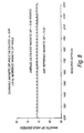
- Figure 7 is a graph showing how the calculated magnetic field strength compares with the reference value;
- Figure 8 is a graph showing how the calculated magnetic field dip compares with the reference value;
- Figure 9 is a graph showing an example of the permanent magnetism calculated by the present invention;
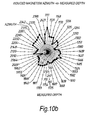
- Figure 10a is a graph showing an example of the induced magnetic field strength estimated by the present invention;
- Figure 10b is a graph showing an example of the induced magnetic field direction estimated by the method of the present invention;
- Figure 11 is a graph illustrating overlapping runs; and
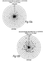
- Figures 12a and 12b are polar graphs showing induced magnetism inclination and direction against rotation respectively.
- Magnetic surveying packages generally comprise a tri-axial accelerometer and a tri-axial magnetometer. The accelerometers measure three independent components of the earth's gravity vector G plus disturbances, and the magnetometers measure three independent components of the earth's magnetic field H plus disturbances. There are thus six independent readings at any time, and each such set of readings is generally termed 'a survey'.
- Figure 1 shows the arrangement and notations for a survey package. The local axes x, y, z form a right handed coordinate system with the z-axis pointing in the direction drilled and the x axis aligned within the drilling pipe to a position on the pipe known as the tool face. The accelerometer and magnetometer axes are aligned along x, y and z. The sensors are calibrated to produced a positive reading when the component of gravity or magnetic field measures points along the corresponding axis. The accelerometers produce a vector of readings gmeas = (gx, gy, gz) and the magnometers produce a vector of flux readings bmeas = (bx, by, bz). In the absence of sources of error these would measure G and B respectively.
- For a person standing on the earth, there is a right-handed world coordinate system X, Y, Z, where Z points down into the earth and is aligned with the gravity vector


- In practical survey packages the sensor axes may not be precisely orthogonal or calibrated to read positively as stated above. By calibration it is possible to derive a matrix of coefficients which when applied to the readings converts them to equivalent orthogonal readings. The drill pipe may have a slight sag or deliberately introduced bend, so that the z-axis of the package is not strictly aligned with the hole axis.
- These details are unimportant to the present invention and do not affect its scope or usefulness. They are cited so as to give an idea of the additional factors that have to be taken into account in realising an accurate survey. For the mathematical analysis below, we shall assume the x and X axes each to be aligned as first stated above and the sensor axes to be truly orthogonal although the technique is more generally applicable.
- In addition it is sometimes the case that one or more of the measurement channels fails, and in that case it is desirable to still be able to deduce survey angles. It will be apparent below that this is possible in the present invention by simply omitting the corresponding measurement equations. Proper use of the invention will then provide indications as to whether the remaining measurements have provided sufficient data to indeed deduce the survey angles, and an indication of the resultant accuracy. Hence we will not need to consider the treatment of failed channels further in this disclosure.
- The primary objective of a directional survey is to calculate the hole azimuth Azi, the hole inclination Inc and the tool face rotation Rot from the high side of the hole. In the absence of measurement errors, these angles are given by the well-known formulae.

range 0 to 360 degrees, the angle being that of a vector (x, y) measured anti-clockwise from the x-axis to the y-axis. - It will be convenient to refer the earth's magnetic flux B and gravity G to the survey package coordinate system. Using the well-known rotation matrix


- The method of the present invention is to compare the survey package measurements with those predicted by a model which takes into account known types of disturbance, and to adjust the parameters of the model in such a way as to reduce the residual differences to a minimum. As a first indication, small residuals will show that the model with inferred parameters has indeed fitted the measurements well. As a second indication, the sensitivity of the residuals to small changes in the inferred parameters indicates whether the data and model are well conditioned, ie that the results are trustworthy.
- Figure 2 provides an example of azimuth corrected using the method disclosed herein, compared with the uncorrected azimuth and two different types of gyro surveys over a long section of hole (1,400 metres). The hole inclination was 40-50 degrees. Gyros have in the past been considered to be of high accuracy but it is now understood in the art that they are very susceptible to horizontal reference and misalignment errors for subterranean use. The separation seen between the gyro curves is typical, as is their correct tracking of changes in hole azimuth.
- The survey package correction method disclosed herein has both corrected the clearly wrong uncorrected azimuth, but equally importantly follows the details on the changes in hole direction. (The gyros were run in the hole after the magnetometers and after hole cleaning and reaming which smoothed the hole changes in direction.) This tracking of detail is not possible when only axial or simply cross-axial permanent magnetic interference is taken into account, as in much prior art.
- The method disclosed herein is seen to be capable of making a valuable improvement in accuracy to the level where gyro and corrected surveys have to be scrutinised equally closely to determine the reasons for their differences.
- Several parameters are need for a realistic model, and it is usually necessary to use the measurements made at several survey levels to ensure more data than unknown parameters.
- There are many mechanisms for the disturbances, which may affect magnetometer and accelerometer readings together or independently. It is an object of the present invention to provide a systematic means of incorporating models of such disturbance mechanisms as they are found to be important, and therefore the examples disclosed below are to be taken as illustrative and important but not exclusive and do not limit the scope of the invention.
- It will also be appreciated that a combination of mechanisms may be implicit in numerical computation of the total disturbances in a computer program, so preventing their separate evaluation, but as a combined model is intended to fall within the scope of the present invention.
- The disturbance models disclosed herein are now described separately for the magnetometers and accelerometers.
- The types of magnetometer disturbance to be modelled are those due to permanent magnetism, induced magnetism and electrical currents. In addition the total earth fields and the magnetic dip are subject to local differences from published tables, and to solar storms and regular variations, as is well known. It is therefore desirable to be able to treat these fields themselves as parameters to be determined, eg not to use suspect a priori values of magnetic dip and total magnetic field, although no particular model of their origin or variation is required.
- The sum of the actual earth's magnetic field and these disturbances is the predicted value of the measured vector, and may be expressed in the local coordinate system as follows:

- This vector expression predicts the three components of the field actually measured by the survey package. Figure 4 illustrates the vector composition of the modelled terms, although it will be understood that the relative magnitudes and directions of the terms may vary widely.
- The first term on the right hand side is the earth's magnetic field, which depends on the five parameters B, MDip, Azi, Inc, Rot, B and MDip. The second term represents the net vector due to permanent magnetism and is independent of hole directions and the earth's field. The third term is an approximation to the effects of induced magnetism. As this is due to the earth's magnetic field, it varies as the hole direction and tool rotation changes between surveys. The final term is the effect of electrical currents.
- The predicted measurement therefore depends on many parameters, collected as a list of arguments on the left hand side of the expression. In the prior art only the permanent magnetic interference (bias or perturbing vector) has been explicitly considered. When the other terms are important it can be seen that ignoring them will give rise to erroneous estimates of permanent magnetism.
- It will be apparent that there are many more parameters in the model than the three components of one survey measurement. In the present invention is preferably dealt with by combining measurements from multiple surveys, in which it is recognised that most parameters are substantially the same for each survey. Azi and Inc may change slowly but it is only Rot that is expected to be effectively random between surveys.
- Then, whereas each survey adds six measurements, the number of parameters is typically increased by only one to three. It will be apparent that if none of the angles Azi, Inc or Rot change measurably between surveys then no new information (as opposed to noise) is added, and the parameter values that are estimated may be unreliable. It is a further aspect of the present invention that a means of assessing the stability of the estimated parameter values is provided, rather than an ad hoc set of rules for minimum changes in the angles required in order to apply the method.
- It will be apparent in this formation that the earth's field quantities B and MDip are considered as parameters to be found, given sufficient measurements, ie the invention when fully applied does not require a priori information, unlike much prior art.
- The most well-known source of disturbance is that due to permanent magnetism in nearby magnetic materials like the magnetic steel of the heavy drill collar and stabilisers (see Figure 3). However, it is possible for the so-called non-magnetic drill-collar (NMDC) surrounding the survey package to suffer from permanent magnetic 'hot-spots' due to deficient metallurgy and/or stress-released effects. All these magnetic poles result in an interfering magnetic flux at the magnetometer. This is substantially constant during consecutive surveys, and is generally only expected to change significantly when the bottom hole assembly is replaced between trips in the hole or when there is a major mechanical shock in the hole.
- Drilling mud may also contain magnetised particles, which constantly circulate through and around the drill pipe. These particles may show an affinity for the drill pipe, building up a coating. The combined effect over consecutive surveys is one of an essentially constant magnetisation.
- Since all these sources of interfering flux emanate from the drilling assembly or are constant around it, and are independent of the earth's field, they may be modelled as a simple vector m which produces a flux offset at the magnetometer:

- Magnetically permeable materials also distort the earth's field directly by induced magnetism. The amount of distortion seen at the magnetometer depends on the size, shape, orientation, relative position and permeability of these materials.
- It is a further aspect of the present invention that such induced magnetic distortion be modelled. It would be possible to produce a complete model taking into account the details of the bottom hole assembly in arbitrary detail, for which substantial computer modelling would be necessary. In practice it is generally sufficient to use approximate models with explicit formulae.
- As an example, the magnetic field induced in a permeable ellipsoid can be expressed in terms of Legendre functions. Prolate ellipsoids approximate the cylindrical shapes of the highly permeable ('magnetic') drill collars above and below the magnetometer.
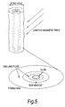
- As a further example, the so-called non-magnetic drill collar in which the survey package is placed may in fact be weakly permeable, so may the package container itself, and the circulating mud may contain permeable materials as illustrated in Figure 5. The effect of these is to partially shield the survey package from the earth's field, as may be noticed in a workshop by the difference in readings seen between the survey package housed and unhoused in so-called non-magnetic collar.
- The relative influence of the induction around the survey package and that from the distant but highly permeable materials depends on the particular construction of a bottom hole assembly. For example it is desirable to reduce the length of non-magnetic collar, as it is expensive, relatively weak in mechanical strength, and increases the distance between survey package and the drilling bit. By reducing this length the 'end' effects of permeable materials is increased, whereas with long non-magnetic collars the end effects are weak.
- The preferred formulae for the induction effect depends on several parameters, an effective scale factor Kp for the near-package induction, and an effective scale factor Ks and effective direction vectors v for the end-effect induction:
- This induced expression is implicitly dependent through be on B, MDip, Azi, Inc and Rot.

- A general induction correction will involve a 3 x 3 matrix of coefficients multiplying the earth's field. However this is unnecessary in practice and introduces many parameters to be found. The above preferred expression fits the circumstances well with fewer parameters.
- The earth's field crossing the survey package is to a first approximation only modified in its transverse components, and assuming the survey package's immediate surroundings to be axisymmetric, these transverse components will be modified in the same way. This is reflected in the first term in the above expression where Kp is a single scale parameter.
- The second part of this expression represents the distortion due to a distant permeable object lying in a direction vs, with a scale factor Kp. Generally it results in correction along each axis which each depend on all the field components in be. If, as is often the case vs is found to be axial, then there is no such mixing of field components. In this case the total correction may be best understood by writing it in the form

- Values of magnetic field inclination and azimunth against drill bit rotation at different points in a borehole are shown in the graphs of Figure 12a and 12b respectively. These graphs show that the induced magnetic field depends largely on rotation of the drill collar, the function being fairly smooth.
- The value of incorporating induction into the model can best be appreciated by realising that it models the shielding effect of permeable materials, ie an effective change in the earth's magnetic field. Using a priori values of the earth's field as in much of the prior art without taking into account shielding effectively forces errors into the survey calculations. Those methods that depend on these priori values to compute survey angles, or use them to correct for permanent magnetism alone cannot match all the benefits of the present invention.
- Survey packages are associated with electronic systems that require electrical power, and hence wires, generators and other components which carry electrical current. The net constant or slowly varying current in any part of the system will generate a magnetic field which may be detectable by the magnetometer. The modelled disturbance from any one such part of the system is the product of a direction vector vc scaled by Kc and the current I, and for the entire system is the sum of such parts:

- The quantities vc and Kc may be determined by experiment by applying the currents in turn; it is important to note that vc is not the direction to the part of the system carrying the current, but the vector which describes the resultant magnetic field at the magnetometer. It can be seen that in the model either the currents are to be treated as parameters or to be measured and treated as a priori values.
- Because of shock, vibration and centripetal forces, surveys are normally taken while drilling has temporarily been stopped.
- Nevertheless when the drill pipe becomes stationary at surface, the stored torque in the drill pipe may be released at the survey depth during the survey, in addition to changes in torque caused by reaction from the drilling assembly when mud is circulating.
- Therefore it is an object of the present invention to allow for a model of accelerometer disturbances. One such model is for a small but constant rate of turn and of longitudinal displacement. Then the x- and y- accelerometers will each see a centripetal component of acceleration and the z- axis accelerometer will see an offset. Instead of a simple time average, the individual time sampled measurements can be treated as a separate survey with parameters for the rate of turn and longitudinal movement. However the main benefits of such a model may be obtained independently of the magnetic field model, ie improvements to the accelerometer readings can be obtained by means independent of the present invention or by the means disclosed in the present invention with terms relating to magnetometers struck out.
- Consequently for the purposes of disclosing the present invention it suffices to have the simplest possible model, viz

- In the disclosure of the means of estimating parameters given below it will be seen that the accelerometer readings are then fully integrated with the magnetometer readings, although no particular sources of accelerometer disturbances are taken into account by this model. It will be apparent that in situations where accelerometer disturbances other than noise or uncertainty in G are important and where they are not to be dealt with as a separate problem, then by incorporating them in the above expression, the method of the present patent can be applied, and it is intended that the scope of the present patent should include such extensions.
- When there are the same number of parameters to be determined as there are measurements, it is possible to solve the parameter estimation problem by requiring the predicted measurements to equal the actual measurements. The resultant nonlinear simultaneous equation may be solved by any of a number of means known in the art of numerical algebra.
- Unfortunately it is often the case with real (imperfectly made) measurements that wide variations in the exactly-determined solutions can result from small changes in the measurements. For example in prior art B and MDip are sometimes given as a priori values, in order to reduce the number of unknowns. When these values are only slightly in error, the resultant solution for Azi can have significant errors. This is particularly the case when the hole direction is near the horizontal along the East-West axis, whereas when drilling North-South the error is likely to be small.
- In the present invention a minimisation method is preferred, in which parameters are chosen so as to minimise the difference between the actual measurements and the predicted measurements. The means of measuring this difference is preferably that of the sum of the squares of the differences between each measurement and the predicted value. The differences are individually scaled to make them comparable with each other.
- The estimation problem is then to find the parameters that minimise

- Here the index j runs over the N different surveys used in the measurements and the index runs over the three measurement axes. With known levels of instrument noise it is reasonable to use the noise standard deviations for the magnetometer and acceleromater scale factors σb and σg respectively. In the absence of credible noise statistics, it is satisfactory to use approximate values of B and G respectively, in which case the square root of the Fit is the root mean square normalised Fit, with Fit0.5=0.0005 indicating a discrepancy between measured and predicted data of around 0.05% of the total field values.
- Figure 6 illustrates the relationship of the parts of this expression, the parameters and the survey data. It shows how the survey measurements are compared to the predicted fields, the differences squared and summed to compute Fit, which is then passed to the minimiser. The latter iteratively makes a new estimate of the parameters, computes the expected fields in the absence of disturbances and uses these with the remaining parameters to update the predicted fields. The iterations are stopped when the Fit is judged to be good. While it is preferred to work in local coordinates, nothing in the method requires this choice, which could be a mix of coordinate systems consistently applied. Furthermore, the illustration of sources of interference can be refined in many ways as described previously without affecting the minimisation process.
- There are several methods well-known in the art of numerical optimisation that can be used to solve this minimisation problem, such as the Leverberg-Marquardy technique, and the method chosen is not important to this invention.
- There are also other measures of Fit that could be used, which do not affect the nature of the present invention. For example, it may be advantageous to use the absolute values of the differences instead of the squares of the differences in the above expression, since this gives less emphasis to inconsistent data. In such cases general numerical minimisation is required, as the least squares structure is lost.
- It is well known in the art of numerical minimisation there is normally no guarantee that the absolute minimum - the best fit - will be found. Thus it is possible that for several choices of parameters small variations in their values will always increase the Fit value, giving various minima. To help ensure that the choices of parameters considered are always reasonable, the preferred implementation of the minimisation routine will employ the technique known in the art of numerical minimisation as constraints. These constraints circumscribe ranges of parameter values that the minimisation will consider.
- In the present invention the constraints include requiring
- a) Kp and Ks to be positive, and to be less than empirically determined cutoffs;
- b) vs to be close to axial
- c) successive values of Azi and Inc not to vary by more than consisent with the drilling assembly's capabilities
- d) B, G, and MDip to be close to their approximately known a priori values, if available.
- When a Fit is found where any of the parameters B, G or MDip are found to be constrained, then this is an indication that there has been a failure in the survey package or a major change such as a magnetic storm has occurred.
- It is important to note that regardless of whether G, B or MDip are given a priori values or are estimated in the minimisation, the predicted fields implicitly incorporate a consistent relationship to them, and there is no need to impose additional constraints in this regard. For example, in the afore-mentioned simple model for gravity, the predicted field will always have the magnitude G.
- When data quality is poor however it is possible for a range of parameters to give similar levels of Fit. To detect this case the present invention calculates the change in root mean square Fit that results from small changes in each parameter.
- A large change in Fit indicates that the parameter is well resolved whereas a small change in Fit indicates that the choice of parameter is for example one of the induced magnetism coefficients, then this merely indicates that induced magnetism is unimportant for the given surveys. On the other hand if the parameter concerned is one of the quantities Azi, Inc, Rot, B, MDip or G then the data is insufficient to provide reliable survey results.
- It is a matter of experiment with typical surveys to judge what value of Fit can be considered good, and what change in Fit for a given parameter change is acceptable.
- The use of multiple surveys will now be described. Sufficient surveys must be used to give more data than unknowns if a good quality correction os to be obtained. Conversely if too many surveys are used then the assumptions on constancy of parameters may be inappropriate. The preferred number of surveys is five, but where more than one source of distortion is found to be large, then the number of surveys should be increased to seven of nine. The quality assurance procedure referred to above indicates when the number of surveys has to be increased.
- If however there are severe changes in the parameters, such as from an apparent change in apparent magnetism, or a large variation in the earth's magnetic field, or at the commencing stages of drilling, then it may not be possible to use as many levels as desired. In this case the number of parameters to be found has to be reduced, possibly by using the simpler version of the induced model, or by introducing a priori values of some parameters and choosing not to use them in the minimisation process.
- When drilling, the corrected hole direction at the last survey depth, k say, necessarily can only be combined with shallower surveys k- 1, k- 2.... However, when the next survey k + 1 is taken, the hole direction at k can be reassessed using the data k + 1, k, k - 1... This preferred method has the merit that it takes into account the later state of the survey system, and helps to confirm that nothing untoward has occurred. In general it is desirable to compute a corrected hole direction using surrounding surveys. In the expression for Fit given above, preferably only the parameter corresponding to the central survey should be used.
- During normal drilling operations the bottom hole assembly is replaced frequently, before extending the hole further on a separate run. Thus surveys are made at similar depths but with different bottom hole assemblies and hence different model parameters. When the surveys from each run have been corrected satisfactorily by means of the invention as so far disclosed, or by other means if any, it is possible to effect a further but smoothed improvement in the hole direction estimate. Thus it is a further aspect of the present invention that surveys from separate runs can be combined into one minimisation, where only those parameter than can sensibly be considered constant between trips are the same in the predicted fields for two runs. For example, Azi and Inc will be made the same and often, G, B and MDip.
- Figures 7 - 11 illustrate various aspects of the invention obtained using actual survey data over a continuously drilled section of 1,400 metres. In Figures 7 and 8 the estimated values of B and MDip are compared to a priori reference data obtained from the well-known IGRF [expand name] model. The differences are less than the expected local variation for the geographical area concerned, and are essentially constant over the full drilled section. Figure 9 shows the three components of permanent magnetic flux, showing firstly the larger axial component and secondly that the cross-axial components are not negligible.
- Figure 10a shows the off-axis angle of the vector vs and Ks in the end-effect induced magnetism correction, which as expected is small. All the magnetic parameters of the drilling assembly are essentially constant as anticipated in the formulation of the invention.
- Figure 10b shows how the azimuth of the induced magnetism varies with depth, which as expected is reasonably constant as the magnetic parameters of the drilling assembly are essentially constant as anticipated.
- Figure 11 shows the results of two runs with different drilling assemblies, corrected separately over an overlapping section of hole . While the corrected azimuths are very similar, the permanent magnetism and the uncorrected azimuths are markedly different.
- Figure 12a shows how the induced magnetism inclination varies with the rotation of the drilling assembly, and Figure 12b shows how the induced magnetism direction varies with the rotation of the of the drilling assembly.
Claims (7)
- A method for calculating the direction of a borehole comprising the steps of taking measurements of gravity and magnetic field, whereby to provide an estimated vector for the earth's gravitational field and magnetic field at the point of measurement, andpredicting the magnetic field vector, based on a plurality of predicted magnetic field components, intended to be substantially similar to corresponding actual components of the magnetic field, the sum of the actual components being substantially similar to the total magnetic field;estimating the gravitational field vector on the basis of measurements taken and predictions of the gravitational field generated by a mathematical model,calculating a measure of the difference between the measured and predicted magnetic and gravitational field vectors;minimising said difference measures by updating the models on which the predicted components are based, whereby to generate new predictions andupdating the direction and estimated parameters of the borehole for use with a later set of measurements.
- The method of claim 1 wherein the difference measures to be minimised include the borehole parameters from all the measurements made during the drilling operation, wherein changes to different mathematical models cause different patterns of change to the sets of predictions.
- The method of claims 1 or 2 wherein the minimisation used to minimise the difference between predicted and actual parameters of the borehole measurements, is based on a least squares hypothesis.
- The method of any of claims 1-3 wherein one of said magnetic field components is the earth's magnetic field.
- The method of any preceding claim wherein one of said magnetic field components is permanent magnetism.
- The method of any preceding claim wherein one of said magnetic field components is an induced magnetic field.
- The method of any preceding claim wherein one of said magnetic field components is generated by electric current.
Applications Claiming Priority (2)
| Application Number | Priority Date | Filing Date | Title |
|---|---|---|---|
| GB9509819 | 1995-05-15 | ||
| GB9509819A GB2301438B (en) | 1995-05-15 | 1995-05-15 | Method for correcting directional surveys |
Publications (3)
| Publication Number | Publication Date |
|---|---|
| EP0793000A2 true EP0793000A2 (en) | 1997-09-03 |
| EP0793000A3 EP0793000A3 (en) | 1998-02-04 |
| EP0793000B1 EP0793000B1 (en) | 2001-10-04 |
Family
ID=10774502
Family Applications (1)
| Application Number | Title | Priority Date | Filing Date |
|---|---|---|---|
| EP19960303391 Expired - Lifetime EP0793000B1 (en) | 1995-05-15 | 1996-05-14 | Method for correcting directional surveys |
Country Status (3)
| Country | Link |
|---|---|
| EP (1) | EP0793000B1 (en) |
| GB (1) | GB2301438B (en) |
| NO (1) | NO316336B1 (en) |
Cited By (16)
| Publication number | Priority date | Publication date | Assignee | Title |
|---|---|---|---|---|
| WO1999064720A1 (en) * | 1998-06-12 | 1999-12-16 | Baker Hughes Incorporated | Method for magnetic survey calibration and estimation of uncertainty |
| US6508316B2 (en) | 1998-05-14 | 2003-01-21 | Baker Hughes Incorporated | Apparatus to measure the earth's local gravity and magnetic field in conjunction with global positioning attitude determination |
| WO2005124102A1 (en) * | 2004-06-21 | 2005-12-29 | Halliburton Energy Services, Inc. | Wellbore surveying |
| US7027926B2 (en) | 2004-04-19 | 2006-04-11 | Pathfinder Energy Services, Inc. | Enhanced measurement of azimuthal dependence of subterranean parameters |
| US7103982B2 (en) | 2004-11-09 | 2006-09-12 | Pathfinder Energy Services, Inc. | Determination of borehole azimuth and the azimuthal dependence of borehole parameters |
| US8195400B2 (en) | 2009-05-08 | 2012-06-05 | Smith International, Inc. | Directional resistivity imaging using harmonic representations |
| US8271199B2 (en) | 2009-12-31 | 2012-09-18 | Smith International, Inc. | Binning method for borehole imaging |
| WO2014092938A1 (en) * | 2012-12-10 | 2014-06-19 | Schlumberger Canada Limited | Weighting function for inclination and azimuth computation |
| EP2818632A2 (en) | 2013-06-25 | 2014-12-31 | Gyrodata, Incorporated | Positioning techniques in multi-well environments |
| US8947094B2 (en) | 2011-07-18 | 2015-02-03 | Schlumber Technology Corporation | At-bit magnetic ranging and surveying |
| US9297249B2 (en) | 2011-06-29 | 2016-03-29 | Graham A. McElhinney | Method for improving wellbore survey accuracy and placement |
| EP2895888A4 (en) * | 2012-09-14 | 2016-06-15 | Scient Drilling Int | Determining local variations of earth's magnetic field |
| CN106522924A (en) * | 2016-11-15 | 2017-03-22 | 北京恒泰万博石油技术股份有限公司 | Acquisition method for azimuth angles in measurement while drilling |
| US9658360B2 (en) | 2010-12-03 | 2017-05-23 | Schlumberger Technology Corporation | High resolution LWD imaging |
| US11175431B2 (en) | 2017-06-14 | 2021-11-16 | Gyrodata, Incorporated | Gyro-magnetic wellbore surveying |
| US11193363B2 (en) | 2017-12-04 | 2021-12-07 | Gyrodata, Incorporated | Steering control of a drilling tool |
Families Citing this family (9)
| Publication number | Priority date | Publication date | Assignee | Title |
|---|---|---|---|---|
| US5960370A (en) * | 1996-08-14 | 1999-09-28 | Scientific Drilling International | Method to determine local variations of the earth's magnetic field and location of the source thereof |
| GB2317454B (en) * | 1996-08-14 | 2001-03-07 | Scient Drilling Int | Method to determine local variations of the earth's magnetic field and location of the source thereof |
| GB9717975D0 (en) | 1997-08-22 | 1997-10-29 | Halliburton Energy Serv Inc | A method of surveying a bore hole |
| US7681663B2 (en) * | 2005-04-29 | 2010-03-23 | Aps Technology, Inc. | Methods and systems for determining angular orientation of a drill string |
| US8280638B2 (en) * | 2009-02-19 | 2012-10-02 | Baker Hughes Incorporated | Multi-station analysis of magnetic surveys |
| US8600115B2 (en) | 2010-06-10 | 2013-12-03 | Schlumberger Technology Corporation | Borehole image reconstruction using inversion and tool spatial sensitivity functions |
| US9273547B2 (en) | 2011-12-12 | 2016-03-01 | Schlumberger Technology Corporation | Dynamic borehole azimuth measurements |
| US9982525B2 (en) | 2011-12-12 | 2018-05-29 | Schlumberger Technology Corporation | Utilization of dynamic downhole surveying measurements |
| GB2623678A (en) * | 2021-09-30 | 2024-04-24 | Halliburton Energy Services Inc | Drilling system with directional survey transmission system and methods of transmission |
Citations (3)
| Publication number | Priority date | Publication date | Assignee | Title |
|---|---|---|---|---|
| EP0384537A1 (en) * | 1989-02-21 | 1990-08-29 | Anadrill International SA | Method to improve directional survey accuracy |
| US5321893A (en) * | 1993-02-26 | 1994-06-21 | Scientific Drilling International | Calibration correction method for magnetic survey tools |
| US5398421A (en) * | 1990-12-12 | 1995-03-21 | Institut Francais Du Petrole Et Societe | Method for connecting magnetic measurements performed in a well through a measuring device in order to determine the azimuth thereof |
-
1995
- 1995-05-15 GB GB9509819A patent/GB2301438B/en not_active Expired - Lifetime
-
1996
- 1996-05-14 NO NO19961966A patent/NO316336B1/en not_active IP Right Cessation
- 1996-05-14 EP EP19960303391 patent/EP0793000B1/en not_active Expired - Lifetime
Patent Citations (3)
| Publication number | Priority date | Publication date | Assignee | Title |
|---|---|---|---|---|
| EP0384537A1 (en) * | 1989-02-21 | 1990-08-29 | Anadrill International SA | Method to improve directional survey accuracy |
| US5398421A (en) * | 1990-12-12 | 1995-03-21 | Institut Francais Du Petrole Et Societe | Method for connecting magnetic measurements performed in a well through a measuring device in order to determine the azimuth thereof |
| US5321893A (en) * | 1993-02-26 | 1994-06-21 | Scientific Drilling International | Calibration correction method for magnetic survey tools |
Cited By (24)
| Publication number | Priority date | Publication date | Assignee | Title |
|---|---|---|---|---|
| US6508316B2 (en) | 1998-05-14 | 2003-01-21 | Baker Hughes Incorporated | Apparatus to measure the earth's local gravity and magnetic field in conjunction with global positioning attitude determination |
| US6179067B1 (en) | 1998-06-12 | 2001-01-30 | Baker Hughes Incorporated | Method for magnetic survey calibration and estimation of uncertainty |
| GB2358251A (en) * | 1998-06-12 | 2001-07-18 | Baker Hughes Inc | Method for magnetic survey calibration and estimation of uncertainty |
| GB2358251B (en) * | 1998-06-12 | 2002-09-04 | Baker Hughes Inc | Method for magnetic survey calibration and estimation of uncertainty |
| WO1999064720A1 (en) * | 1998-06-12 | 1999-12-16 | Baker Hughes Incorporated | Method for magnetic survey calibration and estimation of uncertainty |
| US7403857B2 (en) | 2004-04-19 | 2008-07-22 | Pathfinder Energy Services, Inc. | Enhanced measurement of azimuthal dependence of subterranean parameters with filters and/or discretely sampled data |
| US7027926B2 (en) | 2004-04-19 | 2006-04-11 | Pathfinder Energy Services, Inc. | Enhanced measurement of azimuthal dependence of subterranean parameters |
| NO338056B1 (en) * | 2004-06-21 | 2016-07-25 | Halliburton Energy Services Inc | Progress to determine the presence of magnetic shielding effects when monitoring a well |
| WO2005124102A1 (en) * | 2004-06-21 | 2005-12-29 | Halliburton Energy Services, Inc. | Wellbore surveying |
| US7143521B2 (en) | 2004-11-09 | 2006-12-05 | Pathfinder Energy Services, Inc. | Determination of borehole azimuth and the azimuthal dependence of borehole parameters |
| US7103982B2 (en) | 2004-11-09 | 2006-09-12 | Pathfinder Energy Services, Inc. | Determination of borehole azimuth and the azimuthal dependence of borehole parameters |
| US8195400B2 (en) | 2009-05-08 | 2012-06-05 | Smith International, Inc. | Directional resistivity imaging using harmonic representations |
| US8271199B2 (en) | 2009-12-31 | 2012-09-18 | Smith International, Inc. | Binning method for borehole imaging |
| US9658360B2 (en) | 2010-12-03 | 2017-05-23 | Schlumberger Technology Corporation | High resolution LWD imaging |
| US9297249B2 (en) | 2011-06-29 | 2016-03-29 | Graham A. McElhinney | Method for improving wellbore survey accuracy and placement |
| US8947094B2 (en) | 2011-07-18 | 2015-02-03 | Schlumber Technology Corporation | At-bit magnetic ranging and surveying |
| EP2895888A4 (en) * | 2012-09-14 | 2016-06-15 | Scient Drilling Int | Determining local variations of earth's magnetic field |
| US9134452B2 (en) | 2012-12-10 | 2015-09-15 | Schlumberger Technology Corporation | Weighting function for inclination and azimuth computation |
| WO2014092938A1 (en) * | 2012-12-10 | 2014-06-19 | Schlumberger Canada Limited | Weighting function for inclination and azimuth computation |
| EP2818632A2 (en) | 2013-06-25 | 2014-12-31 | Gyrodata, Incorporated | Positioning techniques in multi-well environments |
| CN106522924A (en) * | 2016-11-15 | 2017-03-22 | 北京恒泰万博石油技术股份有限公司 | Acquisition method for azimuth angles in measurement while drilling |
| CN106522924B (en) * | 2016-11-15 | 2020-01-07 | 北京恒泰万博石油技术股份有限公司 | Method for acquiring azimuth angle in measurement while drilling |
| US11175431B2 (en) | 2017-06-14 | 2021-11-16 | Gyrodata, Incorporated | Gyro-magnetic wellbore surveying |
| US11193363B2 (en) | 2017-12-04 | 2021-12-07 | Gyrodata, Incorporated | Steering control of a drilling tool |
Also Published As
| Publication number | Publication date |
|---|---|
| NO316336B1 (en) | 2004-01-12 |
| NO961966L (en) | 1996-11-18 |
| NO961966D0 (en) | 1996-05-14 |
| GB2301438B (en) | 1999-04-21 |
| GB9509819D0 (en) | 1995-07-05 |
| EP0793000B1 (en) | 2001-10-04 |
| EP0793000A3 (en) | 1998-02-04 |
| GB2301438A (en) | 1996-12-04 |
Similar Documents
| Publication | Publication Date | Title |
|---|---|---|
| EP0793000B1 (en) | Method for correcting directional surveys | |
| US8781744B2 (en) | Downhole surveying utilizing multiple measurements | |
| US6321456B1 (en) | Method of surveying a bore hole | |
| US5452518A (en) | Method of correcting for axial error components in magnetometer readings during wellbore survey operations | |
| US6179067B1 (en) | Method for magnetic survey calibration and estimation of uncertainty | |
| EP0384537B1 (en) | Method to improve directional survey accuracy | |
| EP0615573B1 (en) | Method and apparatus for determining the orientation of the axis of a borehole. | |
| CA2134191C (en) | Method of correcting for axial and transverse error components in magnetometer readings during wellbore survey operations | |
| US8280638B2 (en) | Multi-station analysis of magnetic surveys | |
| CA2212925C (en) | Method to determine local variations of the earth's magnetic field and location of the source thereof | |
| GB2415049A (en) | Determining borehole azimuth from tool face angle measurements | |
| GB2398638A (en) | Passive ranging determining the position of a subterranean magnetic structure from within a nearby borehole | |
| GB2398879A (en) | Determination of rotational offset between two borehole gravity measurement devices | |
| US5623407A (en) | Method of correcting axial and transverse error components in magnetometer readings during wellbore survey operations | |
| US6530154B2 (en) | Method to detect deviations from a wellplan while drilling in the presence of magnetic interference | |
| CA2570080C (en) | Wellbore surveying | |
| Ekseth et al. | High-Integrity Wellbore Surveying | |
| EP0348049B1 (en) | Surveying of boreholes | |
| US6833706B2 (en) | Hole displacement measuring system and method using a magnetic field | |
| CA1240499A (en) | Method for the detection and correction of magnetic interference in the surveying of boreholes | |
| GB2374940A (en) | Surveying of boreholes | |
| GB2251078A (en) | Method for the correction of magnetic interference in the surveying of boreholes | |
| CA2271156C (en) | Method of correcting wellbore magnetometer errors | |
| GB2317454A (en) | Magnetic field measurement in a sub-surface wellpath | |
| WO1996002733A1 (en) | Method of correcting for error components in wellbore survey data |
Legal Events
| Date | Code | Title | Description |
|---|---|---|---|
| PUAI | Public reference made under article 153(3) epc to a published international application that has entered the european phase |
Free format text: ORIGINAL CODE: 0009012 |
|
| AK | Designated contracting states |
Kind code of ref document: A2 Designated state(s): FR GB NL |
|
| PUAL | Search report despatched |
Free format text: ORIGINAL CODE: 0009013 |
|
| AK | Designated contracting states |
Kind code of ref document: A3 Designated state(s): FR GB NL |
|
| 17P | Request for examination filed |
Effective date: 19980803 |
|
| GRAG | Despatch of communication of intention to grant |
Free format text: ORIGINAL CODE: EPIDOS AGRA |
|
| 17Q | First examination report despatched |
Effective date: 20001026 |
|
| GRAG | Despatch of communication of intention to grant |
Free format text: ORIGINAL CODE: EPIDOS AGRA |
|
| GRAH | Despatch of communication of intention to grant a patent |
Free format text: ORIGINAL CODE: EPIDOS IGRA |
|
| RAP1 | Party data changed (applicant data changed or rights of an application transferred) |
Owner name: HALLIBURTON ENERGY SERVICES, INC. |
|
| GRAH | Despatch of communication of intention to grant a patent |
Free format text: ORIGINAL CODE: EPIDOS IGRA |
|
| GRAA | (expected) grant |
Free format text: ORIGINAL CODE: 0009210 |
|
| AK | Designated contracting states |
Kind code of ref document: B1 Designated state(s): FR GB NL |
|
| REG | Reference to a national code |
Ref country code: GB Ref legal event code: IF02 |
|
| ET | Fr: translation filed | ||
| PLBE | No opposition filed within time limit |
Free format text: ORIGINAL CODE: 0009261 |
|
| STAA | Information on the status of an ep patent application or granted ep patent |
Free format text: STATUS: NO OPPOSITION FILED WITHIN TIME LIMIT |
|
| 26N | No opposition filed | ||
| REG | Reference to a national code |
Ref country code: FR Ref legal event code: PLFP Year of fee payment: 20 |
|
| PGFP | Annual fee paid to national office [announced via postgrant information from national office to epo] |
Ref country code: GB Payment date: 20150424 Year of fee payment: 20 |
|
| PGFP | Annual fee paid to national office [announced via postgrant information from national office to epo] |
Ref country code: FR Payment date: 20150424 Year of fee payment: 20 Ref country code: NL Payment date: 20150512 Year of fee payment: 20 |
|
| REG | Reference to a national code |
Ref country code: NL Ref legal event code: MK Effective date: 20160513 |
|
| REG | Reference to a national code |
Ref country code: GB Ref legal event code: PE20 Expiry date: 20160513 |
|
| PG25 | Lapsed in a contracting state [announced via postgrant information from national office to epo] |
Ref country code: GB Free format text: LAPSE BECAUSE OF EXPIRATION OF PROTECTION Effective date: 20160513 |