EP0793115B1 - Laser-Radar-Abtaster mit Millimeter-Auflösung - Google Patents
Laser-Radar-Abtaster mit Millimeter-Auflösung Download PDFInfo
- Publication number
- EP0793115B1 EP0793115B1 EP97101154A EP97101154A EP0793115B1 EP 0793115 B1 EP0793115 B1 EP 0793115B1 EP 97101154 A EP97101154 A EP 97101154A EP 97101154 A EP97101154 A EP 97101154A EP 0793115 B1 EP0793115 B1 EP 0793115B1
- Authority
- EP
- European Patent Office
- Prior art keywords
- light
- pulse
- reference object
- accordance
- photodetector
- Prior art date
- Legal status (The legal status is an assumption and is not a legal conclusion. Google has not performed a legal analysis and makes no representation as to the accuracy of the status listed.)
- Expired - Lifetime
Links
Images


Classifications
-
- G—PHYSICS
- G01—MEASURING; TESTING
- G01C—MEASURING DISTANCES, LEVELS OR BEARINGS; SURVEYING; NAVIGATION; GYROSCOPIC INSTRUMENTS; PHOTOGRAMMETRY OR VIDEOGRAMMETRY
- G01C3/00—Measuring distances in line of sight; Optical rangefinders
- G01C3/02—Details
- G01C3/06—Use of electric means to obtain final indication
- G01C3/08—Use of electric radiation detectors
-
- G—PHYSICS
- G01—MEASURING; TESTING
- G01S—RADIO DIRECTION-FINDING; RADIO NAVIGATION; DETERMINING DISTANCE OR VELOCITY BY USE OF RADIO WAVES; LOCATING OR PRESENCE-DETECTING BY USE OF THE REFLECTION OR RERADIATION OF RADIO WAVES; ANALOGOUS ARRANGEMENTS USING OTHER WAVES
- G01S17/00—Systems using the reflection or reradiation of electromagnetic waves other than radio waves, e.g. lidar systems
- G01S17/02—Systems using the reflection of electromagnetic waves other than radio waves
- G01S17/06—Systems determining position data of a target
- G01S17/08—Systems determining position data of a target for measuring distance only
- G01S17/10—Systems determining position data of a target for measuring distance only using transmission of interrupted, pulse-modulated waves
-
- G—PHYSICS
- G01—MEASURING; TESTING
- G01S—RADIO DIRECTION-FINDING; RADIO NAVIGATION; DETERMINING DISTANCE OR VELOCITY BY USE OF RADIO WAVES; LOCATING OR PRESENCE-DETECTING BY USE OF THE REFLECTION OR RERADIATION OF RADIO WAVES; ANALOGOUS ARRANGEMENTS USING OTHER WAVES
- G01S7/00—Details of systems according to groups G01S13/00, G01S15/00, G01S17/00
- G01S7/48—Details of systems according to groups G01S13/00, G01S15/00, G01S17/00 of systems according to group G01S17/00
- G01S7/483—Details of pulse systems
- G01S7/486—Receivers
- G01S7/4865—Time delay measurement, e.g. time-of-flight measurement, time of arrival measurement or determining the exact position of a peak
-
- G—PHYSICS
- G01—MEASURING; TESTING
- G01S—RADIO DIRECTION-FINDING; RADIO NAVIGATION; DETERMINING DISTANCE OR VELOCITY BY USE OF RADIO WAVES; LOCATING OR PRESENCE-DETECTING BY USE OF THE REFLECTION OR RERADIATION OF RADIO WAVES; ANALOGOUS ARRANGEMENTS USING OTHER WAVES
- G01S7/00—Details of systems according to groups G01S13/00, G01S15/00, G01S17/00
- G01S7/48—Details of systems according to groups G01S13/00, G01S15/00, G01S17/00 of systems according to group G01S17/00
- G01S7/497—Means for monitoring or calibrating
-
- G—PHYSICS
- G01—MEASURING; TESTING
- G01S—RADIO DIRECTION-FINDING; RADIO NAVIGATION; DETERMINING DISTANCE OR VELOCITY BY USE OF RADIO WAVES; LOCATING OR PRESENCE-DETECTING BY USE OF THE REFLECTION OR RERADIATION OF RADIO WAVES; ANALOGOUS ARRANGEMENTS USING OTHER WAVES
- G01S17/00—Systems using the reflection or reradiation of electromagnetic waves other than radio waves, e.g. lidar systems
- G01S17/02—Systems using the reflection of electromagnetic waves other than radio waves
- G01S17/06—Systems determining position data of a target
- G01S17/42—Simultaneous measurement of distance and other co-ordinates
-
- G—PHYSICS
- G01—MEASURING; TESTING
- G01S—RADIO DIRECTION-FINDING; RADIO NAVIGATION; DETERMINING DISTANCE OR VELOCITY BY USE OF RADIO WAVES; LOCATING OR PRESENCE-DETECTING BY USE OF THE REFLECTION OR RERADIATION OF RADIO WAVES; ANALOGOUS ARRANGEMENTS USING OTHER WAVES
- G01S13/00—Systems using the reflection or reradiation of radio waves, e.g. radar systems; Analogous systems using reflection or reradiation of waves whose nature or wavelength is irrelevant or unspecified
- G01S13/88—Radar or analogous systems specially adapted for specific applications
- G01S13/93—Radar or analogous systems specially adapted for specific applications for anti-collision purposes
- G01S13/931—Radar or analogous systems specially adapted for specific applications for anti-collision purposes of land vehicles
- G01S2013/9315—Monitoring blind spots
-
- G—PHYSICS
- G01—MEASURING; TESTING
- G01S—RADIO DIRECTION-FINDING; RADIO NAVIGATION; DETERMINING DISTANCE OR VELOCITY BY USE OF RADIO WAVES; LOCATING OR PRESENCE-DETECTING BY USE OF THE REFLECTION OR RERADIATION OF RADIO WAVES; ANALOGOUS ARRANGEMENTS USING OTHER WAVES
- G01S13/00—Systems using the reflection or reradiation of radio waves, e.g. radar systems; Analogous systems using reflection or reradiation of waves whose nature or wavelength is irrelevant or unspecified
- G01S13/88—Radar or analogous systems specially adapted for specific applications
- G01S13/93—Radar or analogous systems specially adapted for specific applications for anti-collision purposes
- G01S13/931—Radar or analogous systems specially adapted for specific applications for anti-collision purposes of land vehicles
- G01S2013/9327—Sensor installation details
- G01S2013/93274—Sensor installation details on the side of the vehicles
Definitions
- the invention relates to a laser distance determination device with a pulse laser, a light deflection device, one having an optoelectronic photoreceiver Photo receiving arrangement and a control and evaluation electronics, wherein the pulse laser sends out light pulses in a controlled manner and the successively emitted light pulses over the light deflector at changing angles be directed into a measuring range, from one in the measuring range reflected light pulses from the object Photo receiving arrangement can be received and in the control and Evaluation electronics based on the pulse transit time method the time between sending and receiving a light pulse considering the speed of light for the distance of the object from the light deflection device representative sample signal determined and compensation of transit time measurement errors occurring due to the signal dynamics is carried out.
- the first two influencing variables a) and b) result a statistical measurement error caused by averaging can be reduced over several measurements.
- the third influencing variable c which is primarily due to this is that the linear gain range of the usually connected downstream of the optoelectronic photo receiver Preamplifier compared to that in practice occurring signal dynamics is limited. Leads accordingly the laser radar known from DE 43 40 756 A1 Compensation for those occurring due to the signal dynamics Runtime measurement error depending on the measured Peak value of the received light pulse on the basis accordingly determined correction values only in one relative small scale range to the desired result.
- the aim of the invention is to provide a laser distance determination device of the type mentioned at the outset simple and reliable compensation due to the signal dynamics occurring runtime measurement errors guaranteed is, in particular also the different Operating conditions and different reflectivities of the respective property should be taken into account.
- Object reflected light pulse When receiving one from one in the measuring range Object reflected light pulse are then the first during the reception of this light pulse overall over the Electrical receiver or the pulse width of the photoreceptor of this received light pulse, whereupon the corresponding correction value is called up or the corresponding one Correction function can be activated.
- the charge measurement takes place independently of the runtime measurement, i.e. via a separate charge measuring circuit, so that a possible Overriding one of the relevant runtime measuring circuits assigned preamplifier has no influence on the charge measurement Has. In contrast, it is basically possible to To determine pulse width via the respective transit time measurement circuit.
- Runtime measurement errors that occur are now dependent from the measured electrical charge or pulse width, may have an overload and the associated saturation effects of one of the Preamplifier assigned to the transit time measuring circuit has no influence on this compensation.
- a major advantage of the invention Laser distance detection device is particular also seen in the fact that it is not necessary is that a certain reflectivity at a defined Location of the reference object is present. This reference object does not need to be calibrated or aligned. Possible aging effects is of no importance. It is just required that the reference object at a defined distance is arranged by the light deflection device and reflectivities has in practical use also in scenario to be measured.
- the reference object is expediently outside of a defined monitored scanning angle range arranged so that it is continuous outside of this area with itself changing angles deflected transmit pulse light beam is swept over.
- the capture of the respective Objects in the scanning angle range are thus identified by the reference object not bothered.
- the reference object can also be used in Object lying.
- the reference object can also be determined by a specific one Number of reference sub-objects can be formed, the surfaces successively acted upon by the transmitted pulse light beam have different reflectivities.
- the control and evaluation electronics the same distance from the light deflecting device arranged measured subobjects obtained advantageously by a suitable polynomial with each other linked so that there is the possibility of intermediate values if necessary to determine via the polynomial.
- the reference object can advantageously before and / or during the normal operation of the device are sensed, in order to determine the correction values To get measured values. Especially during operation preferably a repeated scan is also possible, whereby the correction values always to the current Operating conditions are adjusted.
- Runtime measurement errors occur in the control and evaluation electronics only then depending on the measured electrical Load and on the basis of correspondingly determined correction values or correction functions if the measured pulse width of the received light pulse a certain one Has exceeded the limit.
- This limit can preferably be at least substantially equal to 2 to 10 times Value of the pulse width of the emitted light pulse. If this limit is exceeded, this is a Indication that the preamplifier in question is extremely clipping is, so that now the compensation is expedient depending on the measured electrical charge can be done.
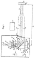
- a motor 31 drives a horizontal turntable 28 to a continuous orbital movement around a vertical Axis 17 on.
- a Angle encoder 29 is provided, which is designed as a fork light barrier is and via a line 32 to a not shown Control stage of a control and evaluation electronics 10 connected is.
- a circular cylinder body 27 is arranged on the turntable 28, that his trained as a rotating mirror 16 upper End face arranged at an angle of 45 ° to the axis of rotation 17 is.
- the rotating mirror 16 can be shown in FIG Way also be formed on a mirror plate that over a mirror support is attached to the turntable 28.
- Above the rotating mirror 16 is a much narrower, also arranged deflecting mirror 19, whose mirror surface is at an angle of 45 ° to the axis of rotation 17 has and also be realized as a circular cylinder body can.
- the deflecting mirror 19 can also be used as a flat mirror plate be trained.
- a central area 24 of the deflecting mirror 19 receives via a transmitting lens 33 and the deflecting mirror 19 light of a pulse laser 11.
- the initially horizontal light beam is on Deflecting mirror 19 deflected downward, then from the rotating mirror 16 in a horizontal direction to a windscreen 41 of the laser radar to be redirected. From there it gets Transmit pulse light beam 21 in the measuring range 13, in which, for example assumed a light reflecting object 14 of the scattered light as a received pulse light bundle 20 through the front window 41 in the sense of an autocollimation beam path back to the rotating mirror 16.
- the received pulse light beam 20 strikes the side of the central one Area 24 on which the transmission light 21 and in particular the central incidence light beam 18 impinges on a ring area 47 of the rotating mirror 16 in order to pass the deflecting mirror 19 to be reflected to an interference filter 26 behind which a receiver lens 25 is arranged.
- This receiver lens 25 has areas 25 ', 25' 'of different focal lengths on to also very close to the laser radar To be able to recognize objects perfectly.
- the receiver lens 25 concentrates the received light a photo receiver 23. It forms together with the photo receiver 23 a photo receiving arrangement 22.
- the rotating mirror 16, the turntable 28 and the motor 31 are Part of a light deflecting device 15 which transmits the pulse light beam 21 and received pulse light bundle 20 about the axis of rotation 17 can rotate around.
- FIG. 1 In addition to the top view according to FIG. 1, there are two in FIG further angular positions of the rotating mirror 16 and the transmission pulse light beam 21 shown.
- An angular scan performing transmit pulse light bundle 21 defines a scanning plane 53.
- the maximum scanning angle range 54 extends 2 over 180 °.
- the light deflection device 15 with the Control and evaluation electronics 10 coupled For example, it will rotated at a speed of 1,500 rpm. Generally, this speed can range in particular from 500 to 10,000 rpm.
- Via line 32 becomes one of the control and evaluation electronics, for example 10 assigned control level from the angle encoder 29 at any moment the angular position of the light deflecting device 15 communicated.
- light pulses 12 are sent into the measuring area 13. After a running time t they are received light pulses 12 '(see FIG. 1) of the photo receiving arrangement 22 receive.
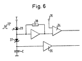
- a photodiode in particular, an avalanche diode-formed photo receiver 23 (see FIGS. 1, 5 and 6) generates a corresponding one electrical signal through a preamplifier when embodiment shown a transimpedance amplifier 38 (see FIG. 6) and then an entrance a comparator 34 is supplied.
- This comparator 34 also has a detection threshold 79 (cf.
- the Transimpedance amplifier 28 and the comparator 34 are the control and evaluation electronics 10 (cf. Figure 1) assigned.
- FIG. 6 are also means for measuring the during Receipt of a light pulse 12 'overall via the photo receiver 23 flowed electrical charge provided the one via a Schottky diode 37 with the photodetector 23 capacitor C connected in series and one of these downstream buffer amplifier 36 include.
- the free End of capacitor C is grounded, while the cathode of the photoreceptor 23 to generate a corresponding one Bias is at a potential V.
- This means C, 36, 37 for measuring the during reception of a light pulse 12 'in total via the photoreceiver 23 flowed electrical charge are just like the means 34, 38 for measuring the pulse width of the received light pulse 12 'or part of the control and evaluation electronics for measuring the transit time 10 (see FIG. 1).
- the output signal of the comparator 34 can, for example, be on a counter clocked by a frequency generator (not shown) of the control and evaluation electronics 10 his.
- the control and evaluation electronics 10 can in particular also include a microprocessor.
- the microprocessor of the control and evaluation electronics 10 via line 32 also the current angular position of the light deflection device 15 communicated appropriate information about the polar coordinates of the object 14, for example, to a again associated with the control and evaluation electronics 10 Interface are passed on, where they are then for further Use for example as a navigation signal or error signal is available.
- a by the transmitted pulse light beam 21 surface 30 of the A blackened ring aperture 87 is provided for reference object 86 that prevents unwanted stray light effects.
- This surface 30 can be of high output reflectivity provided, increasingly overpainted with black paint Foil, primer or the like can be formed.
- the reference object 86 can also be carried out by a certain number of reference part objects are formed be, preferably at a distance from each other to the axis of rotation 17 of the rotatable light deflection device 15 concentric arc lie, the one after the other areas acted upon by the transmission and pulse light bundle 21 of the different reference sub-objects different Have reflectivities.
- control and evaluation electronics 10 with respect to the same distance from the light deflector 15 arranged partial test objects received measured values linked together by a polynomial and intermediate values can be determined via the polynomial.
- 5 is that formed by a laser radar Laser distance detection device in a housing 115 housed, in the lower area the over 180 ° curved Front window 41 is provided.
- FIG. 3 there are three different ones over the optoelectronic Photo receiver 23 of the photo receiving arrangement 22 received and via the transimpedance amplifier serving as a preamplifier 38 (see FIG. 6) amplified light pulses 12 '. These reach a maximum signal voltage of 80, 81 and 82. Due to a correspondingly low noise level exceed all received light impulses 12 'that set at the reference input 35 of the comparator 34 Detection threshold 79. However, the time t after which the rising edge of the three different received Light pulses 12 'exceeds the detection threshold 79, differently. In the example shown, the Time difference up to for example 1.2 ns what corresponds to a measurement error of approximately 20 cm.
- timing errors (For example 84, 85 for the signals with the maximum values 80, 81) with respect to the base time 83 for the light pulse 12 'with the largest maximum value 82 can, for example in the microprocessor of the control and evaluation electronics 10 saved and available accordingly for correction purposes be put.
- the transimpedance amplifier 38 in this case the transimpedance amplifier 38 (see FIG. 6) in the linear amplification range is operated, it is in principle possible the compensation of those occurring due to the signal dynamics Runtime measurement error depending on the maximum or Peak values 80, 81, 82 (see FIG. 3) to make what possible for example by means of a peak value detector is.
- control and evaluation electronics 10 now designed so that the compensation due to the Signal dynamics occurring runtime measurement errors based on the already described means C, 36, 37; 34, 38 for measuring the overall during the reception of a light pulse 12 ' the electrical charge or the photo receiver 23 for measuring the pulse width of the received light pulse 12 'as a function of the measured electrical charge or pulse width and on the basis of respective Correction values are carried out by the control and evaluation electronics 10 based on charges or pulse widths and pulse transit times be determined with respect to the at least one, at a defined distance from the light deflecting device 15 arranged different reflectivities having reference object 86 (cf. FIG. 5) were.
- the control and evaluation electronics 10 can now be used for Compensation required correction values based on the Charges or pulse widths and pulse transit times determined are measured with respect to the reference object 86 were.
- the target runtime is determined, with which the actually measured pulse transit times can be compared can.
- the runtime deviations can then be used as a measure of the serve respective correction values or correction functions.
- the resulting correction values can, for example, in the control and evaluation electronics 10 are stored.
- Is then subsequently in the scanning angle range 54 detects a respective object 14 (cf. FIG. 1), see above are based on the received light pulse the total while receiving the light pulse the photo receiver 23 flowed electrical charge and / or the pulse width of the received light pulse is measured, whereupon the assigned, previously determined correction value called up or a corresponding correction function can be activated.
- a possibly occurring Overdrive and related saturation effects of Pre-amplifiers or transimpedance amplifiers 38 have none Influence on the compensation in question and thus the Accuracy of distance measurement.
- the means for measuring the during the reception of a light pulse 12 'in total over the Photoelectric receiver 23 flowed over the the Schottky diode 37 with the optoelectronic photo receiver 23 series-connected capacitor C and this downstream buffer amplifier 36 (see FIG. 6).
- the pulse widths can, for example, by means of a also assigned to the control and evaluation electronics 10, meter, not shown, can be measured using the output signal of the comparator 34 (see FIG. 6) becomes.
- the output signal of this comparator 34 is here Case used simultaneously for the runtime measurement.
- a higher measuring accuracy can be achieved among other things that during a certain number of samples obtained with respect to the reference object 86 Measured values in the control and evaluation electronics 10 averaged become.
- the control and evaluation electronics 10 is designed so that the compensation the transit time measurement error occurring due to the signal dynamics only then depending on the measured electrical Cargo and determined on the basis accordingly Correction values are made when the measured pulse width of the received light pulse 12 'a certain limit has exceeded.
- This limit can, for example, at least substantially equal to the value of the pulse width of the be emitted light pulse 12. This limit is thus an indication that the preamplifier or transimpedance amplifier 38 was overridden (see FIG. 4, overridden Signal).
- the compensation takes place beforehand, for example depending on the pulse widths measured in each case.
- the reference object 86 does not have to be calibrated or aligned become. Aging effects have no influence.
- the Reflectivities of the surface 30 of the reference object 86 are expediently chosen so that either all in the outer Reflectivity occurring or taken into account certain reference points are formed by a Appropriate order polynomial can be linked to To be able to determine intermediate values based on the polynomial.
- the reference object can be used before and / or during normal operation of the laser radar can be scanned in order to determine the to obtain the measurement values required for the correction values. Particularly during operation, there is preferably also one Repeated sampling possible, reducing the correction values always be adapted to the current operating conditions.
- the laser distance determination device and in particular their control and evaluation electronics designed in this way be like this in the above DE 43 40 756 A1 is described.
Description
- Figur 1
- in schematischer Ansicht den Grundaufbau eines als Laserradar verwirklichten Laserabstandsermittlungsvorrichtung,
- Figur 2
- eine schematische Draufsicht auf den Drehspiegel nach Figur 1 und den Abtastwinkelbereich,
- Figur 3
- ein Signalspannungs-Zeitdiagramm verschieden starker Empfangslichtimpulse,
- Figur 4
- ein weiteres Signalspannungs-Zeitdiagramm verschieden starker Empfangslichtimpulse, wobei zwei im Linearbereich des betreffenden Vorverstärkers liegenden Signalen ein bei einer Übersteuerung erhaltenes Signal gegenübergestellt ist,
- Figur 5
- eine Ansicht analog Figur 1 in einer um 90° gedrehten Position des Drehspiegels zur Veranschaulichung der Funktion eines in den Strahlengang eingebrachten Referenzobjekts,
- Figur 6
- einen die Ladungsmessungsmittel umfassenden Teil der Steuer- und Auswerteelektronik des Laserradars und
- Figur 7
- eine Korrekturkurve einer Amplitudenkorrektur.
- 10
- Steuer- und Auswerteelektronik
- 11
- Impulslaser
- 12
- gesendete Lichtimpulse
- 12'
- empfangene Lichtimpulse
- 13
- Meßbereich
- 14
- Objekt
- 15
- Lichtablenkeinrichtung
- 16
- Drehspiegel
- 17
- Gehäuse
- 18
- Mitteleinfallslichtstrahl
- 19
- Umlenkspiegel
- 20
- Empfangs-Impulslichtbündel
- 21
- Sende-Impulslichtbündel
- 22
- Photoempfängeranordnung
- 23
- optoelektronischer Photoempfänger
- 24
- zentraler Bereich
- 25
- Empfängerlinse
- 25', 25''
- Bereiche unterschiedlicher Brennweite
- 26
- Interferenzfilter
- 27
- Kreiszylinderkörper
- 28
- Drehteller
- 29
- Winkelgeber
- 30
- Fläche
- 31
- Motor
- 32
- Leitung
- 33
- Sendelinse
- 34
- Komparator
- 35
- Referenzeingang
- 36
- Pufferverstärker
- 37
- Schottky-Diode
- 38
- Transimpedanzverstärker
- 41
- Frontscheibe
- 47
- Ringbereich
- 53
- Abtastebene
- 54
- Abtastwinkelbereich
- 79
- Detektionsschwelle
- 80
- Signalspannung
- 81
- Signalspannung
- 82
- Signalspannung
- 83
- Basiszeit
- 84
- Zeitmeßfehler
- 85
- Zeitmeßfehler
- 86
- Referenzobjekt
- 87
- Ringblende
- 115
- Gehäuse
- C
- Kondensator
Claims (10)
- Laserabstandsermittlungsvorrichtung mit einem Impulslaser (11), einer Lichtablenkeinrichtung (15), einer einen optoelektronischen Photoempfänger (23) aufweisenden Photoempfangsanordnung (22) und einer Steuer- und Auswerteelektronik (10), wobei der Impulslaser (11) gesteuert Lichtimpulse (12) aussendet und die aufeinanderfolgend ausgesendeten Lichtimpulse (12) über die Lichtablenkeinrichtung (15) unter sich verändernden Winkeln in einen Messbereich (13) gelenkt werden, von einem im Messbereich (13) befindlichen Objekt (14) zurückgeworfene Lichtimpulse (12') von der Photoempfangsanordnung (22) empfangen werden und in der Steuer- und Auswerteelektronik (10) nach dem Impulslaufzeitverfahren aus der Zeit zwischen dem Aussenden und dem Empfang eines Lichtimpulses (12,12') unter Berücksichtigung der Lichtgeschwindigkeit ein für den Abstand des Objektes (14) von der Lichtablenkeinrichtung (15) repräsentatives Abtastsignal ermittelt sowie eine Kompensation von aufgrund der Signaldynamik auftretenden Laufzeitmessfehlern durchgeführt wird,
dadurch gekennzeichnet, dass die Steuer- und Auswerteelektronik (10) Mittel (C, 36, 37; 34, 38) zum Messen der während des Empfangs eines Lichtimpulses (12') insgesamt über den Photoempfänger (23) geflossenen elektrischen Ladung und zum Messen der Impulsbreite des empfangenden Lichtimpulses (12') umfasst und dass die Kompensation der aufgrund der Signaldynamik auftretenden Laufzeitmessfehler in Abhängigkeit von der gemessenen elektrischen Ladung bzw. Impulsbreite auf der Basis von jeweiligen Korrekturwerten erfolgt, die durch die Steuer- und Auswerteelektronik (10) anhand von Ladungen bzw. Impulsbreiten und Impulslaufzeiten ermittelt werden, die bezüglich wenigstens eines in definiertem Abstand von der Lichtablenkeinrichtung (15) angeordneten, unterschiedliche Reflektivitäten aufweisenden Referenzobjekts (86) gemessen wurden, wobei die Kompensation der aufgrund der Signaldynamik auftretenden Laufzeitmessfehler in der Steuer- und Auswerteelektronik (10) erst dann in Abhängigkeit von der gemessenen elektrischen Ladung und auf der Basis entsprechend ermittelter Korrekturwerte bzw. Korrekturfunktionen erfolgt, wenn die gemessene Impulsbreite des empfangenen Lichtimpulses (12') einen bestimmten Grenzwert überschritten hat. - Vorrichtung nach Anspruch 1,
dadurch gekennzeichnet , daß das Referenzobjekt (86) außerhalb eines definierten überwachten Abtastwinkelbereichs (54) angeordnet ist und vom mit sich kontinuierlich ändernden Winkeln abgelenkten Sende-Impulslichtbündel (21) überstrichen wird, und/oder daß das Referenzobjekt (86) eine vom Sende-Im pulslichtbündel (21) beaufschlagten Fläche (30) von sich vorzugsweise stufenlos ändernder Reflektivitä auf weist, die sich entlang eines zur Drehachse (17)der drehbaren Lichtablenkeinrichtung (15) konzentrischen Kreisbogens erstreckt, wobei sich die Reflektivität entlang des Kreisbogens ändert, wobei insbesondere die Fläche (30) durch eine mit hoher Ausgangsreflektivität versehene, zunehmend mit schwarzer Farbe überlackierte Folie, Grundierung oder dergleichen gebildet ist. - Vorrichtung nach Anspruch 1 oder 2,
dadurch gekennzeichnet , daß das Referenzobjekt (86) durch eine bestimmte Anzahl von Referenzteilobjekten gebildet ist, die vorzugsweise in gegenseitigem Abstand auf einem zur Drehachse (17) der drehbaren Lichtablenkeinrichtung (15) konzentrischen Kreisbogen liegen, und daß die nacheinander vom Sende-Impulslichtbündel (21) beaufschlagten Flächen der verschiedenen Referenzteilobjekte unterschiedliche Reflektivitäten aufweisen, wobei insbesondere in der Steuer- und Auswerteelektronik (10) die bezüglich der in gleichem Abstand von der Lichtablenkeinrichtung (15) angeordneten Referenzteilobjekte erhaltenen Meßwerte durch ein Polynom miteinander verknüft und Zwischenwerte über das Polynom ermittelt werden. - Vorrichtung nach einem der vorhergehenden Ansprüche,
dadurch gekennzeichnet , daß die Lichtablenkeinrichtung (15) einen 360°-Ablenkwinkel überstreicht und vorzugsweise kontinuierlich in einer Drehrichtung umläuft und/oder daß die Mittel (C, 36, 37) zum Messen der während des Empfangs eines Lichtimpulses (12') insgesamt über den Photoempfänger (23) geflossenen elektrischen Ladung einen mit dem Photoempfänger (23) in Reihe geschalteten Kondensator (C) sowie einen diesem nachgeschalteten Pufferverstärker (36) umfassen, wobei insbesondere der Kondensator (C) über eine Diode, vorzugsweise eine Schottky-Diode (37) mit dem Photoempfänger (23) in Reihe geschaltetet ist. - Vorrichtung nach einem der vorhergehenden Ansprüche,
dadurch gekennzeichnet , daß der Photoempfänger (23) über einen Vorverstärker, vorzugsweise einen Transimpedanzverstärker (38) mit einem Eingang eines Komparators (34) verbunden ist, der zudem mit einem eine Detektionsschwelle (79) definierenden Referenzeingang (35) versehen ist und dessen Ausgangssignal insbesondere zum Messen der Impulsbreite des empfangenen Lichtimpulses (12') herangezogen wird, wobei insbesondere das Ausgangssignal des Komparators (34) gleichzeitig zur Laufzeitmessung herangezogen wird. - Vorrichtung nach einem der vorhergehenden Ansprüche, dadurch gekennzeichnet , daß das Referenzobjekt (86) vor und/oder während des normalen Betriebs der Vorrichtung vorzugsweise wiederholt abgetastet wird, um die zur Ermittlung der Korrekturwerte erforderlichen Meßwerte zu erhalten, und/oder daß während einer bestimmten Anzahl von Abtastungen bezüglich des Referenzobjekts (86) erhaltene Meßwerte zur Verbesserung der Genauigkeit in der Steuerund Auswerteelektronik (10) gemittelt werden.
- Vorrichtung nach einem der vorhergehenden Ansprüche, dadurch gekennzeichnet , daß insbesondere der Grenzwert zumindest im wesentlichen gleich dem Wert der 2- bis 10-fachen, insbesondere der 2- bis 5-fachen Impulsbreite des ausgesendeten Lichtimpulses (12) ist bzw. einem Wert entspricht, bei dem der Vorverstärker stark übersteuert ist.
- Vorrichtung nach einem der vorhergehenden Ansprüche, dadurch gekennzeichnet , daß die Steuer- und Auswerteelektronik (10) zur Bestimmung der Laufzeiten und Impulsbreiten eine Zeitmeßeinheit umfaßt.
- Vorrichtung nach einem der vorhergehenden Ansprüche, dadurch gekennzeichnet , daß die Steuer- und Auswerteelektronik (10) einen Mikroprozessor umfaßt.
- Vorrichtung nach einem der vorhergehenden Ansprüche, dadurch gekennzeichnet , daß der optoelektronische Photoempfänger eine Photodiode, insbesondere eine Lawinendiode (23) ist.
Applications Claiming Priority (2)
| Application Number | Priority Date | Filing Date | Title |
|---|---|---|---|
| DE19607345 | 1996-02-27 | ||
| DE19607345A DE19607345A1 (de) | 1996-02-27 | 1996-02-27 | Laserabstandsermittlungsvorrichtung |
Publications (3)
| Publication Number | Publication Date |
|---|---|
| EP0793115A2 EP0793115A2 (de) | 1997-09-03 |
| EP0793115A3 EP0793115A3 (de) | 1998-06-10 |
| EP0793115B1 true EP0793115B1 (de) | 2004-10-06 |
Family
ID=7786564
Family Applications (1)
| Application Number | Title | Priority Date | Filing Date |
|---|---|---|---|
| EP97101154A Expired - Lifetime EP0793115B1 (de) | 1996-02-27 | 1997-01-24 | Laser-Radar-Abtaster mit Millimeter-Auflösung |
Country Status (5)
| Country | Link |
|---|---|
| US (1) | US5949530A (de) |
| EP (1) | EP0793115B1 (de) |
| JP (1) | JP4024896B2 (de) |
| DE (2) | DE19607345A1 (de) |
| ES (1) | ES2225906T3 (de) |
Cited By (2)
| Publication number | Priority date | Publication date | Assignee | Title |
|---|---|---|---|---|
| DE202010007683U1 (de) | 2010-06-08 | 2011-10-04 | Sick Ag | Optischer Lichttaster |
| RU2755650C1 (ru) * | 2020-12-24 | 2021-09-17 | Акционерное общество "ЭЙРБУРГ" | Способ сканирования подстилающей поверхности по курсу |
Families Citing this family (138)
| Publication number | Priority date | Publication date | Assignee | Title |
|---|---|---|---|---|
| JPH11183599A (ja) * | 1997-12-18 | 1999-07-09 | Mitsubishi Electric Corp | 光レーダ装置 |
| DE19831534C1 (de) * | 1998-07-14 | 1999-09-16 | Leuze Electronic Gmbh & Co | Optoelektronische Vorrichtung |
| SE521173C2 (sv) * | 1998-09-17 | 2003-10-07 | Spectra Prec Ab | Elektronisk distansmätanordning |
| JP3574602B2 (ja) * | 1999-12-27 | 2004-10-06 | ペンタックス株式会社 | 3次元画像入力装置 |
| JP3574607B2 (ja) * | 2000-05-02 | 2004-10-06 | ペンタックス株式会社 | 3次元画像入力装置 |
| DE10026534A1 (de) * | 2000-05-27 | 2002-02-28 | Diehl Munitionssysteme Gmbh | Laserentfernungsmesseinrichtung für einen Zünder |
| DE10027239A1 (de) | 2000-05-31 | 2001-12-06 | Sick Ag | Verfahren zur Abstandsmessung und Abstandsmeßeinrichtung |
| US6429429B1 (en) * | 2000-06-22 | 2002-08-06 | Ford Global Technologies, Inc. | Night vision system utilizing a diode laser illumination module and a method related thereto |
| EP1176430B1 (de) * | 2000-07-27 | 2008-09-10 | Leuze electronic GmbH + Co. KG | Optoelektronische Vorrichtung |
| WO2002010681A1 (de) * | 2000-08-01 | 2002-02-07 | Mirko Essling | Messanordnung und messverfahren zur entfernungs- und/oder positionsbestimmung |
| DE10059240A1 (de) | 2000-08-01 | 2002-02-21 | Michael Kasper | Meßanordnung und Meßverfahren |
| ATE481650T1 (de) * | 2000-10-06 | 2010-10-15 | Leica Geosystems Ag | Entfernungsmessgerät |
| US6611318B2 (en) | 2001-03-23 | 2003-08-26 | Automatic Timing & Controls, Inc. | Adjustable mirror for collimated beam laser sensor |
| DE10115152A1 (de) | 2001-03-27 | 2002-10-10 | Hella Kg Hueck & Co | Verfahren zur Abstandsmessung mittels Laufzeitmessung von Laserimpulsen für Fahrzeuge |
| US6801875B1 (en) * | 2001-04-18 | 2004-10-05 | Caliper Life Sciences, Inc. | Methods, systems, and software for performing measurements |
| DE10143107A1 (de) * | 2001-09-03 | 2003-03-20 | Sick Ag | Optoelektronische Entfernungsmeßeinrichtung |
| DE10153270A1 (de) | 2001-10-29 | 2003-05-08 | Sick Ag | Optoelektronische Entfernungsmesseinrichtung |
| DE10163925A1 (de) * | 2001-12-22 | 2003-07-03 | Conti Temic Microelectronic | Verfahren zur Abstandsmessung |
| US7154591B2 (en) * | 2003-01-31 | 2006-12-26 | The Boeing Company | Laser range finding apparatus |
| US6781677B1 (en) | 2003-01-31 | 2004-08-24 | The Boeing Company | Laser range finding apparatus |
| EP1450128A1 (de) * | 2003-02-19 | 2004-08-25 | Leica Geosystems AG | Verfahren und Vorrichtung zur Ableitung geodätischer Entfernungsinformationen |
| JP3875665B2 (ja) * | 2003-07-31 | 2007-01-31 | 北陽電機株式会社 | スキャニング型レンジセンサ |
| DE10346951B4 (de) * | 2003-10-09 | 2011-04-14 | Diehl Bgt Defence Gmbh & Co. Kg | Verfahren und Einrichtung zur Diskriminierung einer Umweltstörung wie Tarnnebel, Rauch oder dergleichen |
| DE10362330B4 (de) * | 2003-10-09 | 2011-07-21 | Diehl BGT Defence GmbH & Co. KG, 88662 | Verfahren und Einrichtung zur Diskriminierung einer Umweltstörung wie Tarnnebel, Rauch oder dergleichen |
| JP3908226B2 (ja) * | 2004-02-04 | 2007-04-25 | 日本電産株式会社 | スキャニング型レンジセンサ |
| US8192137B2 (en) | 2004-05-03 | 2012-06-05 | Jervis B. Webb Company | Automatic transport loading system and method |
| US7980808B2 (en) * | 2004-05-03 | 2011-07-19 | Jervis B. Webb Company | Automatic transport loading system and method |
| US8210791B2 (en) * | 2004-05-03 | 2012-07-03 | Jervis B. Webb Company | Automatic transport loading system and method |
| WO2005108246A2 (en) * | 2004-05-03 | 2005-11-17 | Jervis B. Webb Company | Automatic transport loading system and method |
| US8075243B2 (en) | 2004-05-03 | 2011-12-13 | Jervis B. Webb Company | Automatic transport loading system and method |
| EP1619342B1 (de) * | 2004-07-22 | 2009-04-29 | Bea S.A. | Thermo-empfindliche Vorrichtung zur Anwesenheitsbestimmung von automatischen Türen |
| ES2300680T3 (es) * | 2004-07-22 | 2008-06-16 | Bea S.A. | Dispositivo de escaneo por luz para deteccion cercano a puertas automaticas. |
| DE102004053686A1 (de) * | 2004-11-03 | 2006-05-04 | Essling, Mirko | Laserempfangseinrichtung mit verbesserter Genauigkeit und geringerem Stromverbrauch |
| US20060276958A1 (en) * | 2005-06-02 | 2006-12-07 | Jervis B. Webb Company | Inertial navigational guidance system for a driverless vehicle utilizing laser obstacle sensors |
| JP4819403B2 (ja) | 2005-06-06 | 2011-11-24 | 株式会社トプコン | 距離測定装置 |
| DE102006031580A1 (de) | 2006-07-03 | 2008-01-17 | Faro Technologies, Inc., Lake Mary | Verfahren und Vorrichtung zum dreidimensionalen Erfassen eines Raumbereichs |
| WO2008008210A2 (en) * | 2006-07-12 | 2008-01-17 | Apache Technologies, Inc. | Handheld laser light detector with height correction, using a gps receiver to provide two-dimensional position data |
| USRE46672E1 (en) | 2006-07-13 | 2018-01-16 | Velodyne Lidar, Inc. | High definition LiDAR system |
| JP4116052B2 (ja) * | 2006-09-14 | 2008-07-09 | 北陽電機株式会社 | 測距装置 |
| GB0625442D0 (en) * | 2006-12-20 | 2007-01-31 | Csl Surveys Stevenage Ltd | Profiling device |
| DE102007011417A1 (de) * | 2007-03-08 | 2008-09-11 | Siemens Ag | Vorrichtung und Verfahren zur Entfernungsbestimmung |
| JP2008267920A (ja) * | 2007-04-18 | 2008-11-06 | Ihi Corp | レーザ測距装置およびレーザ測距方法 |
| EP1990656A1 (de) | 2007-05-07 | 2008-11-12 | Sick Ag | Dämpungsglied mit PIN-Dioden für optischen Entfernungsmesser |
| DE102008018139A1 (de) * | 2008-04-10 | 2009-10-15 | Hella Kgaa Hueck & Co. | Optische Sensoreinrichtung |
| KR101018135B1 (ko) | 2008-08-04 | 2011-02-25 | 삼성전기주식회사 | 자율주행체의 공간 스캔 장치 |
| KR101046040B1 (ko) | 2008-09-23 | 2011-07-01 | 삼성전기주식회사 | 자율주행체의 공간 스캔 장치 |
| JP5359361B2 (ja) * | 2008-09-25 | 2013-12-04 | 株式会社デンソー | 車両ドア開度制御装置 |
| KR101026030B1 (ko) | 2008-10-21 | 2011-03-30 | 삼성전기주식회사 | 거리 측정 장치 |
| KR101141451B1 (ko) | 2008-11-11 | 2012-05-04 | 삼성전기주식회사 | 3차원 공간 스캔 장치 |
| KR101004839B1 (ko) | 2008-11-11 | 2010-12-28 | 삼성전기주식회사 | 3차원 공간 스캔 장치 |
| JP2010175488A (ja) * | 2009-01-31 | 2010-08-12 | Keyence Corp | 光走査型光電スイッチ |
| DE102009010465B3 (de) | 2009-02-13 | 2010-05-27 | Faro Technologies, Inc., Lake Mary | Laserscanner |
| JP5310098B2 (ja) * | 2009-03-02 | 2013-10-09 | 株式会社デンソーウェーブ | レーザ距離測定装置 |
| JP2010204015A (ja) * | 2009-03-05 | 2010-09-16 | Denso Wave Inc | レーザレーダ装置 |
| US9551575B2 (en) | 2009-03-25 | 2017-01-24 | Faro Technologies, Inc. | Laser scanner having a multi-color light source and real-time color receiver |
| KR101018203B1 (ko) | 2009-03-25 | 2011-02-28 | 삼성전기주식회사 | 거리 측정 장치 |
| DE102009015920B4 (de) | 2009-03-25 | 2014-11-20 | Faro Technologies, Inc. | Vorrichtung zum optischen Abtasten und Vermessen einer Umgebung |
| DE102009035336B3 (de) | 2009-07-22 | 2010-11-18 | Faro Technologies, Inc., Lake Mary | Vorrichtung zum optischen Abtasten und Vermessen einer Umgebung |
| DE102009035337A1 (de) | 2009-07-22 | 2011-01-27 | Faro Technologies, Inc., Lake Mary | Verfahren zum optischen Abtasten und Vermessen eines Objekts |
| JP5696324B2 (ja) * | 2009-09-29 | 2015-04-08 | 富士通株式会社 | 走行体 |
| US9113023B2 (en) | 2009-11-20 | 2015-08-18 | Faro Technologies, Inc. | Three-dimensional scanner with spectroscopic energy detector |
| DE102009057101A1 (de) | 2009-11-20 | 2011-05-26 | Faro Technologies, Inc., Lake Mary | Vorrichtung zum optischen Abtasten und Vermessen einer Umgebung |
| US9529083B2 (en) | 2009-11-20 | 2016-12-27 | Faro Technologies, Inc. | Three-dimensional scanner with enhanced spectroscopic energy detector |
| DE102009055988B3 (de) | 2009-11-20 | 2011-03-17 | Faro Technologies, Inc., Lake Mary | Vorrichtung zum optischen Abtasten und Vermessen einer Umgebung |
| US9210288B2 (en) | 2009-11-20 | 2015-12-08 | Faro Technologies, Inc. | Three-dimensional scanner with dichroic beam splitters to capture a variety of signals |
| DE102009055989B4 (de) * | 2009-11-20 | 2017-02-16 | Faro Technologies, Inc. | Vorrichtung zum optischen Abtasten und Vermessen einer Umgebung |
| JP5263273B2 (ja) * | 2009-11-30 | 2013-08-14 | 株式会社デンソーウェーブ | レーザ測定装置 |
| US9163922B2 (en) | 2010-01-20 | 2015-10-20 | Faro Technologies, Inc. | Coordinate measurement machine with distance meter and camera to determine dimensions within camera images |
| US9607239B2 (en) | 2010-01-20 | 2017-03-28 | Faro Technologies, Inc. | Articulated arm coordinate measurement machine having a 2D camera and method of obtaining 3D representations |
| US9879976B2 (en) | 2010-01-20 | 2018-01-30 | Faro Technologies, Inc. | Articulated arm coordinate measurement machine that uses a 2D camera to determine 3D coordinates of smoothly continuous edge features |
| US9628775B2 (en) | 2010-01-20 | 2017-04-18 | Faro Technologies, Inc. | Articulated arm coordinate measurement machine having a 2D camera and method of obtaining 3D representations |
| JP5192614B1 (ja) | 2010-01-20 | 2013-05-08 | ファロ テクノロジーズ インコーポレーテッド | 座標測定デバイス |
| DE102010020925B4 (de) | 2010-05-10 | 2014-02-27 | Faro Technologies, Inc. | Verfahren zum optischen Abtasten und Vermessen einer Umgebung |
| JP5626770B2 (ja) * | 2010-06-08 | 2014-11-19 | 株式会社Ihiエアロスペース | レーザ距離測定装置 |
| DE102010032723B3 (de) | 2010-07-26 | 2011-11-24 | Faro Technologies, Inc. | Vorrichtung zum optischen Abtasten und Vermessen einer Umgebung |
| DE102010032724A1 (de) * | 2010-07-26 | 2012-01-26 | Faro Technologies, Inc. | Vorrichtung zum optischen Abtasten und Vermessen einer Umgebung |
| DE102010032725B4 (de) | 2010-07-26 | 2012-04-26 | Faro Technologies, Inc. | Vorrichtung zum optischen Abtasten und Vermessen einer Umgebung |
| DE102010032726B3 (de) | 2010-07-26 | 2011-11-24 | Faro Technologies, Inc. | Vorrichtung zum optischen Abtasten und Vermessen einer Umgebung |
| DE102010033561B3 (de) | 2010-07-29 | 2011-12-15 | Faro Technologies, Inc. | Vorrichtung zum optischen Abtasten und Vermessen einer Umgebung |
| US9168654B2 (en) | 2010-11-16 | 2015-10-27 | Faro Technologies, Inc. | Coordinate measuring machines with dual layer arm |
| US8619239B2 (en) * | 2011-01-28 | 2013-12-31 | Analog Modules Inc. | Accuracy of a laser rangefinder receiver |
| JP2013068582A (ja) * | 2011-09-26 | 2013-04-18 | Denso Wave Inc | レーザレーダ装置 |
| DE102012100609A1 (de) | 2012-01-25 | 2013-07-25 | Faro Technologies, Inc. | Vorrichtung zum optischen Abtasten und Vermessen einer Umgebung |
| EP2677340A1 (de) * | 2012-06-18 | 2013-12-25 | Hexagon Technology Center GmbH | Distanzmessverfahren mit dynamischer Pulsweitenanpassung |
| EP2682780B1 (de) * | 2012-07-04 | 2014-04-23 | Sick Ag | Verfahren zur sicheren Erfassung und Positionsbestimmung von Objekten und Sicherheitsvorrichtung |
| US8997362B2 (en) | 2012-07-17 | 2015-04-07 | Faro Technologies, Inc. | Portable articulated arm coordinate measuring machine with optical communications bus |
| KR101380888B1 (ko) * | 2012-07-24 | 2014-04-02 | 현대모비스 주식회사 | 차간 거리 산출 장치 및 방법 |
| DE102012107544B3 (de) | 2012-08-17 | 2013-05-23 | Faro Technologies, Inc. | Vorrichtung zum optischen Abtasten und Vermessen einer Umgebung |
| WO2014039623A1 (en) | 2012-09-06 | 2014-03-13 | Faro Technologies, Inc. | Laser scanner with additional sensing device |
| DE112013004489T5 (de) | 2012-09-14 | 2015-05-28 | Faro Technologies, Inc. | Laserscanner mit Dynamischer Einstellung der Winkel-Abtastgeschwindigkeit |
| US10067231B2 (en) | 2012-10-05 | 2018-09-04 | Faro Technologies, Inc. | Registration calculation of three-dimensional scanner data performed between scans based on measurements by two-dimensional scanner |
| US9513107B2 (en) | 2012-10-05 | 2016-12-06 | Faro Technologies, Inc. | Registration calculation between three-dimensional (3D) scans based on two-dimensional (2D) scan data from a 3D scanner |
| DE102012109481A1 (de) | 2012-10-05 | 2014-04-10 | Faro Technologies, Inc. | Vorrichtung zum optischen Abtasten und Vermessen einer Umgebung |
| US9823351B2 (en) | 2012-12-18 | 2017-11-21 | Uber Technologies, Inc. | Multi-clad fiber based optical apparatus and methods for light detection and ranging sensors |
| US9470520B2 (en) | 2013-03-14 | 2016-10-18 | Apparate International C.V. | LiDAR scanner |
| US9573607B2 (en) | 2013-03-15 | 2017-02-21 | Kanawha Scales & Systems, Inc. | System for accurate measurement of vehicle speeds for low speed industrial applications |
| CN103197321B (zh) * | 2013-03-22 | 2015-07-15 | 北京航空航天大学 | 一种全波形激光雷达系统 |
| JP2014194380A (ja) * | 2013-03-29 | 2014-10-09 | Denso Wave Inc | レーザ測定装置 |
| CN104459672B (zh) * | 2013-09-13 | 2017-02-01 | 中国地震局地震研究所 | 一种激光发射时刻动态控制方法 |
| CA2931055C (en) | 2013-11-22 | 2022-07-12 | Ottomotto Llc | Lidar scanner calibration |
| US9606228B1 (en) | 2014-02-20 | 2017-03-28 | Banner Engineering Corporation | High-precision digital time-of-flight measurement with coarse delay elements |
| JP6054994B2 (ja) * | 2015-01-29 | 2016-12-27 | シャープ株式会社 | 距離測定装置 |
| JP6482427B2 (ja) * | 2015-07-30 | 2019-03-13 | 三菱電機株式会社 | レーザレーダ装置 |
| DE102015122844A1 (de) | 2015-12-27 | 2017-06-29 | Faro Technologies, Inc. | 3D-Messvorrichtung mit Batteriepack |
| JP2017129426A (ja) * | 2016-01-19 | 2017-07-27 | 株式会社デンソー | レーザレーダ装置 |
| US10627490B2 (en) | 2016-01-31 | 2020-04-21 | Velodyne Lidar, Inc. | Multiple pulse, LIDAR based 3-D imaging |
| JP6739746B2 (ja) * | 2016-03-10 | 2020-08-12 | 株式会社リコー | 物体検出装置、センシング装置、及び物体検出方法 |
| JP7149256B2 (ja) | 2016-03-19 | 2022-10-06 | ベロダイン ライダー ユーエスエー,インコーポレイテッド | Lidarに基づく3次元撮像のための統合された照射及び検出 |
| JP7165587B2 (ja) | 2016-06-01 | 2022-11-04 | ベロダイン ライダー ユーエスエー,インコーポレイテッド | 多重ピクセル走査lidar |
| DE102016122334A1 (de) * | 2016-11-21 | 2018-05-24 | Pepperl + Fuchs Gmbh | Optische Messvorrichtung zum Überwachen und Erfassen von Objekten in einem Überwachungsbereich |
| US10359507B2 (en) | 2016-12-30 | 2019-07-23 | Panosense Inc. | Lidar sensor assembly calibration based on reference surface |
| DE102017101945A1 (de) * | 2017-02-01 | 2018-08-02 | Osram Opto Semiconductors Gmbh | Messanordnung mit einem optischen Sender und einem optischen Empfänger |
| EP3361282B1 (de) * | 2017-02-13 | 2020-03-18 | Leuze electronic GmbH + Co. KG | Optischer sensor mit begrenzerschaltung |
| US10386465B2 (en) | 2017-03-31 | 2019-08-20 | Velodyne Lidar, Inc. | Integrated LIDAR illumination power control |
| JP2020519881A (ja) | 2017-05-08 | 2020-07-02 | ベロダイン ライダー, インク. | Lidarデータ収集及び制御 |
| CN107167813A (zh) * | 2017-05-19 | 2017-09-15 | 深圳市瑞大科技有限公司 | 光学雷达 |
| JP2019012104A (ja) * | 2017-06-29 | 2019-01-24 | 日本電産株式会社 | ハウジングおよびハウジングユニット |
| KR102506438B1 (ko) * | 2017-07-06 | 2023-03-06 | 삼성전자주식회사 | 거리 측정 장치 및 그 방법 |
| JP6953233B2 (ja) * | 2017-08-24 | 2021-10-27 | 株式会社トプコン | 3次元測量装置 |
| US11467256B2 (en) * | 2017-11-01 | 2022-10-11 | Luminar, Llc | Detection of crosstalk and jamming pulses with lidar system |
| DE102017125587A1 (de) | 2017-11-02 | 2019-05-02 | Pepperl + Fuchs Gmbh | Optischer Sensor zum Nachweis von Objekten in einem Erfassungsbereich |
| US11294041B2 (en) | 2017-12-08 | 2022-04-05 | Velodyne Lidar Usa, Inc. | Systems and methods for improving detection of a return signal in a light ranging and detection system |
| US10830881B2 (en) * | 2018-03-20 | 2020-11-10 | Panosense Inc. | Active signal detection using adaptive identification of a noise floor |
| KR102508988B1 (ko) * | 2018-09-04 | 2023-03-09 | 현대모비스 주식회사 | 라이다 센싱장치 |
| EP3623849B1 (de) * | 2018-09-12 | 2023-01-18 | Leuze electronic GmbH + Co. KG | Optischer sensor |
| US10712434B2 (en) | 2018-09-18 | 2020-07-14 | Velodyne Lidar, Inc. | Multi-channel LIDAR illumination driver |
| US11082010B2 (en) | 2018-11-06 | 2021-08-03 | Velodyne Lidar Usa, Inc. | Systems and methods for TIA base current detection and compensation |
| US11885958B2 (en) | 2019-01-07 | 2024-01-30 | Velodyne Lidar Usa, Inc. | Systems and methods for a dual axis resonant scanning mirror |
| KR102299264B1 (ko) | 2019-01-16 | 2021-09-07 | 삼성전자주식회사 | 라이다 장치 |
| CN109917355A (zh) * | 2019-03-04 | 2019-06-21 | 合肥嘉东光学股份有限公司 | 激光雷达距离误差补偿系统 |
| US11681030B2 (en) * | 2019-03-05 | 2023-06-20 | Waymo Llc | Range calibration of light detectors |
| CN112534301A (zh) * | 2019-04-09 | 2021-03-19 | 华为技术有限公司 | 一种测距方法、装置及设备 |
| US10613203B1 (en) | 2019-07-01 | 2020-04-07 | Velodyne Lidar, Inc. | Interference mitigation for light detection and ranging |
| JP7391650B2 (ja) | 2019-08-06 | 2023-12-05 | 株式会社トプコン | 測量装置 |
| WO2021059638A1 (ja) * | 2019-09-25 | 2021-04-01 | パナソニックIpマネジメント株式会社 | 距離測定装置 |
| US11747453B1 (en) | 2019-11-04 | 2023-09-05 | Waymo Llc | Calibration system for light detection and ranging (lidar) devices |
| DE202019106397U1 (de) * | 2019-11-15 | 2020-07-29 | Leuze Electronic Gmbh & Co. Kg | Lichtschrankenanordnung |
| DE102020103794B4 (de) | 2020-02-13 | 2021-10-21 | Daimler Ag | Verfahren zur Kalibrierung eines Lidarsensors |
Citations (1)
| Publication number | Priority date | Publication date | Assignee | Title |
|---|---|---|---|---|
| US5291262A (en) * | 1989-03-27 | 1994-03-01 | Dunne Jeremy G | Laser surveying instrument |
Family Cites Families (26)
| Publication number | Priority date | Publication date | Assignee | Title |
|---|---|---|---|---|
| DE289610C (de) * | ||||
| US4239388A (en) * | 1974-07-29 | 1980-12-16 | The United States Of America As Represented By The Secretary Of The Air Force | Time domain laser reconnaissance technique |
| DE2546714A1 (de) * | 1975-10-17 | 1977-04-21 | Siemens Ag | Verfahren zum messen des abstandes von und der geschwindigkeitskomponente eines objektes senkrecht zu einer bezugslinie |
| DE2607187C3 (de) * | 1976-02-23 | 1986-07-10 | Krautkrämer GmbH, 5000 Köln | Verfahren zur Messung des zeitlichen Impulsabstandes von zwei elektrischen Impulsen |
| JPS5596475A (en) * | 1979-01-19 | 1980-07-22 | Nissan Motor Co Ltd | Obstacle detector for vehicle |
| DE3219452C2 (de) * | 1981-06-09 | 1986-04-24 | MTC, Meßtechnik und Optoelektronik AG, Neuenburg/Neuchâtel | Dynamik-Steuerungsanordnung für ein Entfernungsmeßgerät |
| DE3219423C2 (de) * | 1981-06-09 | 1986-04-30 | MTC, Meßtechnik und Optoelektronik AG, Neuenburg/Neuchâtel | Entfernungsmeßverfahren und Vorrichtung zu seiner Durchführung |
| DE3215847C2 (de) * | 1982-04-28 | 1985-10-31 | MTC, Meßtechnik und Optoelektronik AG, Neuenburg/Neuchâtel | Zeitmeßverfahren und Vorrichtung zu seiner Durchführung |
| US4743856A (en) * | 1983-09-26 | 1988-05-10 | Simulaser Corporation | Digital optical receiver circuit |
| DD289610A5 (de) * | 1986-06-16 | 1991-05-02 | Carl Zeiss Jena Gmbh,De | Laserentfernungsmesser |
| GB2205640A (en) * | 1987-05-11 | 1988-12-14 | Janusz Andrew Veltze | Non-contact measurement of distance to and between surfaces of an object |
| US4939476A (en) * | 1988-12-27 | 1990-07-03 | Crawford Ian D | Laser Rangefinder receiver preamplifier |
| JPH0381687A (ja) * | 1989-08-23 | 1991-04-08 | Nec Corp | レーザ測距装置 |
| US5162643A (en) * | 1991-02-26 | 1992-11-10 | Imra America, Inc. | Light detecting system |
| DE4108376C2 (de) * | 1991-03-15 | 1995-05-11 | Jenoptik Jena Gmbh | Verfahren und Schaltungsanordnung zur Erfassung und Auswertung von Signalen bei der Entfernungsmessung |
| DE4119797C2 (de) * | 1991-06-15 | 1994-02-24 | Leuze Electronic Gmbh & Co | Einen Sender, einen Empfänger und eine Schaltungsanordnung zur Signalauswertung aufweisende Überwachungseinrichtung |
| DE4219260C2 (de) * | 1992-06-12 | 1994-07-14 | Leuze Electronic Gmbh & Co | Lichtelektrische Vorrichtung mit einem Testobjekt |
| DE4233379C1 (de) * | 1992-10-05 | 1994-03-31 | Leica Ag Heerbrugg | Verfahren und Vorrichtung zur relativen Sichtweitenbestimmung |
| DE4340756C5 (de) * | 1992-12-08 | 2006-08-10 | Sick Ag | Laserabstandsermittlungsvorrichtung |
| US5286969A (en) * | 1993-01-28 | 1994-02-15 | At&T Bell Laboratories | Apparatus for measuring optical power in an optical receiver with a non-linear element and a transconductance amplifier |
| DE4304344A1 (de) * | 1993-02-13 | 1994-08-18 | Leuze Electronic Gmbh & Co | Verfahren zum Eliminieren des spiegelnden Anteils einer von einem Objekt reflektierten Lichtstrahlung |
| DE4305011C2 (de) * | 1993-02-18 | 1995-03-23 | Deutsche Aerospace | Pulslaufzeit-Meßverfahren |
| JP2941593B2 (ja) * | 1993-03-02 | 1999-08-25 | 三菱電機株式会社 | 距離測定装置 |
| JPH07225276A (ja) * | 1994-02-10 | 1995-08-22 | Mitsubishi Electric Corp | 車両用光レーダ装置 |
| JP3564800B2 (ja) * | 1994-08-30 | 2004-09-15 | 株式会社デンソー | 距離測定装置 |
| US5682229A (en) * | 1995-04-14 | 1997-10-28 | Schwartz Electro-Optics, Inc. | Laser range camera |
-
1996
- 1996-02-27 DE DE19607345A patent/DE19607345A1/de not_active Ceased
-
1997
- 1997-01-24 DE DE59711979T patent/DE59711979D1/de not_active Expired - Lifetime
- 1997-01-24 ES ES97101154T patent/ES2225906T3/es not_active Expired - Lifetime
- 1997-01-24 EP EP97101154A patent/EP0793115B1/de not_active Expired - Lifetime
- 1997-02-13 US US08/800,162 patent/US5949530A/en not_active Expired - Lifetime
- 1997-02-19 JP JP03481397A patent/JP4024896B2/ja not_active Expired - Lifetime
Patent Citations (1)
| Publication number | Priority date | Publication date | Assignee | Title |
|---|---|---|---|---|
| US5291262A (en) * | 1989-03-27 | 1994-03-01 | Dunne Jeremy G | Laser surveying instrument |
Cited By (2)
| Publication number | Priority date | Publication date | Assignee | Title |
|---|---|---|---|---|
| DE202010007683U1 (de) | 2010-06-08 | 2011-10-04 | Sick Ag | Optischer Lichttaster |
| RU2755650C1 (ru) * | 2020-12-24 | 2021-09-17 | Акционерное общество "ЭЙРБУРГ" | Способ сканирования подстилающей поверхности по курсу |
Also Published As
| Publication number | Publication date |
|---|---|
| EP0793115A3 (de) | 1998-06-10 |
| US5949530A (en) | 1999-09-07 |
| EP0793115A2 (de) | 1997-09-03 |
| JP4024896B2 (ja) | 2007-12-19 |
| DE19607345A1 (de) | 1997-08-28 |
| JPH1020035A (ja) | 1998-01-23 |
| ES2225906T3 (es) | 2005-03-16 |
| DE59711979D1 (de) | 2004-11-11 |
Similar Documents
| Publication | Publication Date | Title |
|---|---|---|
| EP0793115B1 (de) | Laser-Radar-Abtaster mit Millimeter-Auflösung | |
| EP2927711B1 (de) | Laserscanner und Verfahren zur sicheren Erfassung von Objekten | |
| EP1936400B1 (de) | Laserscanner | |
| EP3415950B1 (de) | Distanzmesser mit spad-anordnung und range walk kompensation | |
| EP2469296B1 (de) | Optoelektronischer Sensor und Verfahren zur Erfassung und Abstandsbestimmung von Objekten | |
| EP2541273B1 (de) | Erfassung und Abstandsbestimmung von Objekten | |
| EP0396865B1 (de) | Optisches Radar | |
| EP3355076A1 (de) | Optoelektronischer sensor und verfahren zur bestimmung der entfernung eines objekts in einem überwachungsbereich | |
| EP0066889A2 (de) | Dynamik-Steuerungsanordnung für ein Entfernungsmessgerät | |
| DE102013100696B3 (de) | Optoelektronischer Sensor und Verfahren zur Erfassung von Objekten in einem Überwachungsbereich | |
| EP1990657A1 (de) | Optischer Entfernungsmesser | |
| EP3091369A1 (de) | Laserscanner | |
| EP3270182A1 (de) | Optoelektronischer sensor und verfahren zur erfassung eines objekts in einem überwachungsbereich | |
| EP2182379B1 (de) | Entfernungsmessender Laserscanner | |
| DE10143107A1 (de) | Optoelektronische Entfernungsmeßeinrichtung | |
| EP3770633B1 (de) | Optoelektronischer sensor und verfahren zur abstandsbestimmung | |
| DE19831534C1 (de) | Optoelektronische Vorrichtung | |
| DE3219452A1 (de) | Dynamik-steuerungsanordnung fuer ein entfernungsmessgeraet | |
| EP2431766A1 (de) | Optischer Scanner mit Verschmutzungsüberwachung | |
| EP3361282B1 (de) | Optischer sensor mit begrenzerschaltung | |
| DE102004029343B4 (de) | Zielführungsvorrichtung für ein Fluggerät | |
| DE102010064682B3 (de) | Optoelektronischer Sensor und Verfahren zur Erfassung und Abstandsbestimmung von Objekten | |
| EP4249950B1 (de) | Erfassung und abstandsbestimmung eines objekts | |
| EP4249949B1 (de) | Erfassung und abstandsbestimmung eines objekts | |
| DE202019100793U1 (de) | Optoelektronischer Sensor zur Erfassung von Objekten |
Legal Events
| Date | Code | Title | Description |
|---|---|---|---|
| PUAI | Public reference made under article 153(3) epc to a published international application that has entered the european phase |
Free format text: ORIGINAL CODE: 0009012 |
|
| AK | Designated contracting states |
Kind code of ref document: A2 Designated state(s): BE CH DE ES FR GB IT LI NL |
|
| PUAL | Search report despatched |
Free format text: ORIGINAL CODE: 0009013 |
|
| AK | Designated contracting states |
Kind code of ref document: A3 Designated state(s): BE CH DE ES FR GB IT LI NL |
|
| 17P | Request for examination filed |
Effective date: 19981012 |
|
| 17Q | First examination report despatched |
Effective date: 20030228 |
|
| GRAP | Despatch of communication of intention to grant a patent |
Free format text: ORIGINAL CODE: EPIDOSNIGR1 |
|
| GRAS | Grant fee paid |
Free format text: ORIGINAL CODE: EPIDOSNIGR3 |
|
| GRAA | (expected) grant |
Free format text: ORIGINAL CODE: 0009210 |
|
| AK | Designated contracting states |
Kind code of ref document: B1 Designated state(s): BE CH DE ES FR GB IT LI NL |
|
| REG | Reference to a national code |
Ref country code: GB Ref legal event code: FG4D Free format text: NOT ENGLISH |
|
| REG | Reference to a national code |
Ref country code: CH Ref legal event code: EP |
|
| REF | Corresponds to: |
Ref document number: 59711979 Country of ref document: DE Date of ref document: 20041111 Kind code of ref document: P |
|
| GBT | Gb: translation of ep patent filed (gb section 77(6)(a)/1977) |
Effective date: 20041215 |
|
| REG | Reference to a national code |
Ref country code: ES Ref legal event code: FG2A Ref document number: 2225906 Country of ref document: ES Kind code of ref document: T3 |
|
| ET | Fr: translation filed | ||
| PLBE | No opposition filed within time limit |
Free format text: ORIGINAL CODE: 0009261 |
|
| STAA | Information on the status of an ep patent application or granted ep patent |
Free format text: STATUS: NO OPPOSITION FILED WITHIN TIME LIMIT |
|
| 26N | No opposition filed |
Effective date: 20050707 |
|
| PGFP | Annual fee paid to national office [announced via postgrant information from national office to epo] |
Ref country code: GB Payment date: 20130122 Year of fee payment: 17 Ref country code: CH Payment date: 20130123 Year of fee payment: 17 Ref country code: ES Payment date: 20130122 Year of fee payment: 17 Ref country code: FR Payment date: 20130207 Year of fee payment: 17 |
|
| PGFP | Annual fee paid to national office [announced via postgrant information from national office to epo] |
Ref country code: BE Payment date: 20130121 Year of fee payment: 17 Ref country code: NL Payment date: 20130121 Year of fee payment: 17 |
|
| BERE | Be: lapsed |
Owner name: *SICK A.G. Effective date: 20140131 |
|
| REG | Reference to a national code |
Ref country code: NL Ref legal event code: V1 Effective date: 20140801 |
|
| REG | Reference to a national code |
Ref country code: CH Ref legal event code: PL |
|
| GBPC | Gb: european patent ceased through non-payment of renewal fee |
Effective date: 20140124 |
|
| PG25 | Lapsed in a contracting state [announced via postgrant information from national office to epo] |
Ref country code: NL Free format text: LAPSE BECAUSE OF NON-PAYMENT OF DUE FEES Effective date: 20140801 Ref country code: CH Free format text: LAPSE BECAUSE OF NON-PAYMENT OF DUE FEES Effective date: 20140131 Ref country code: LI Free format text: LAPSE BECAUSE OF NON-PAYMENT OF DUE FEES Effective date: 20140131 |
|
| REG | Reference to a national code |
Ref country code: FR Ref legal event code: ST Effective date: 20140930 |
|
| PG25 | Lapsed in a contracting state [announced via postgrant information from national office to epo] |
Ref country code: GB Free format text: LAPSE BECAUSE OF NON-PAYMENT OF DUE FEES Effective date: 20140124 Ref country code: FR Free format text: LAPSE BECAUSE OF NON-PAYMENT OF DUE FEES Effective date: 20140131 |
|
| PG25 | Lapsed in a contracting state [announced via postgrant information from national office to epo] |
Ref country code: BE Free format text: LAPSE BECAUSE OF NON-PAYMENT OF DUE FEES Effective date: 20140131 |
|
| REG | Reference to a national code |
Ref country code: ES Ref legal event code: FD2A Effective date: 20150407 |
|
| PG25 | Lapsed in a contracting state [announced via postgrant information from national office to epo] |
Ref country code: ES Free format text: LAPSE BECAUSE OF NON-PAYMENT OF DUE FEES Effective date: 20140125 |
|
| PGFP | Annual fee paid to national office [announced via postgrant information from national office to epo] |
Ref country code: DE Payment date: 20160119 Year of fee payment: 20 Ref country code: IT Payment date: 20160122 Year of fee payment: 20 |
|
| REG | Reference to a national code |
Ref country code: DE Ref legal event code: R071 Ref document number: 59711979 Country of ref document: DE |