EP0793164A2 - Docking station for portable computer - Google Patents
Docking station for portable computer Download PDFInfo
- Publication number
- EP0793164A2 EP0793164A2 EP97300480A EP97300480A EP0793164A2 EP 0793164 A2 EP0793164 A2 EP 0793164A2 EP 97300480 A EP97300480 A EP 97300480A EP 97300480 A EP97300480 A EP 97300480A EP 0793164 A2 EP0793164 A2 EP 0793164A2
- Authority
- EP
- European Patent Office
- Prior art keywords
- connector
- docking
- bus
- docking unit
- port
- Prior art date
- Legal status (The legal status is an assumption and is not a legal conclusion. Google has not performed a legal analysis and makes no representation as to the accuracy of the status listed.)
- Granted
Links
Images


Classifications
-
- G—PHYSICS
- G06—COMPUTING; CALCULATING OR COUNTING
- G06F—ELECTRIC DIGITAL DATA PROCESSING
- G06F1/00—Details not covered by groups G06F3/00 - G06F13/00 and G06F21/00
- G06F1/16—Constructional details or arrangements
-
- G—PHYSICS
- G06—COMPUTING; CALCULATING OR COUNTING
- G06F—ELECTRIC DIGITAL DATA PROCESSING
- G06F1/00—Details not covered by groups G06F3/00 - G06F13/00 and G06F21/00
- G06F1/16—Constructional details or arrangements
- G06F1/1613—Constructional details or arrangements for portable computers
- G06F1/1632—External expansion units, e.g. docking stations
Definitions
- the present invention relates to a so-called docking unit for a portable computer, that is mechanically coupled with and is electrically connected to the portable computer to expand the peripheral environment of the portable computer.
- a docking unit can be constituted more easily with the selected functions required by a user.
- a notebook computer portability is the most important feature, having to attach or detach a cable (e.g., a printer cable, a monitor cable, a communication cable) each time a notebook computer is used, whether in or outside an office, is a very complicated task that adversely affects the usability of the unit.
- a cable e.g., a printer cable, a monitor cable, a communication cable
- a docking station also called an “expansion box” or an “expansion unit”
- a notebook computer when a notebook computer is used in an office, makes it possible to provide with a notebook computer the same working environment as that of a desktop computer, while at the same time not adversely affecting portability.
- the primary functions of a docking station are "Port Replication” and "Bus Expansion”.
- Port replication is realized by providing a docking station with connection ports for notebook computer expansion. In other words, when a cable has been connected to each port of a docking station in advance, a user need only dock a notebook computer in the docking station to immediately secure the use of a printer, an external monitor, and a network.
- the port replication function is also called a "cable management" function.
- the bus expansion function is realized by a docking station possessing the capability to expand the bus in a notebook computer, and having at least one bus slot. By docking a notebook computer in a docking station, it is possible for a user to employ desired adaptor cards and devices via the docking station. In other words, no special limitations are placed on the user of a notebook computer.
- a docking station is disclosed in, for example, the specifications for Japanese Patent Application No. Hei 05-181593 (Internal docket No.: JA9-93-027; European application 943053800.1), and in Japanese Patent Application No. Hei 06-134124 (Internal docket No.: JA9-94-030; European application 95304122.5), both of which are assigned to the present applicant.
- Fig. 16 a typical notebook computer 100 and docking station 200.
- the notebook computer 100 has a connector for use when docking (hereinafter referred to as a "docking connector"; not shown in Figure 16).
- the docking connector generally consists of several tens to several hundreds of connector pins, with each connector pin being assigned for a port signal line or a bus signal line in the notebook computer 100.
- the bus that the notebook computer 100 allocates for the docking connector is normally an ISA (Industry Standard Architecture) bus, which is a standard input/output bus. This is because the ISA bus has long been the de facto standard in this field, and there is a very wide range of available ISA devices and ISA applications.
- ISA Industry Standard Architecture
- PCI Peripheral Component Interconnect
- the docking station 200 comprises a main body that incorporates electric circuitry; a mounting portion whereat the notebook computer 100 is mounted on the top surface of the main body; and a projection portion that projects upward from the rear end of the mounting portion.
- a connector is provided on the front surface of the projection portion to engage a docking connector provided on the rear surface of the notebook computer 100.
- the surface of the connector may be covered with a lid freely opened and closed in order to protect the connector when it is not used.
- a pair of linear protrusions are so formed along both sides of the mounting portion. A notebook computer is guided along these linear protrusions when it is being mounted.
- the forms of the docking stations vary, and range from relatively small ones that have only a port replication function, to relatively large ones that can afford to provide a plurality of storage spaces (also called “media bays") in which fixed or detachable memory devices (hard disk drives (HDDs), floppy disk drives (FDDs), compact disk read only memory (CD-ROM) drives, etc.) can be accommodated, and that can provide at least one bus slot for inserting an adaptor card.
- HDDs hard disk drives
- FDDs floppy disk drives
- CD-ROM compact disk read only memory
- all the types of docking stations have essentially the following shortcomings.
- a moderate solution for the problem can be proposed whereby the bus expansion function of a docking station is augmented in anticipation of the up-grading of a system configuration in the future, that is, an extra bus slot and a media bay are provided.
- the expense to users is increased.
- the port replication function of the docking station has more commonality with each other than the bus expansion function. Therefore, it is very wasteful to exchange an entire docking station only because the configuration of the bus expansion function does not match the perceived need.
- the invention provides a docking station, adapted to receive a portable computer, comprising:
- said second docking unit further includes space for retaining a peripheral device connected to a bus expanded through said third connector, and at least one bus slot to connect an expansion adaptor card to said bus expanded through said third connector.
- connection ports include at least one of an FDD port, a CRT port, a serial port, a parallel port, a keyboard port and a mouse port, and said bus signal lines are PCI bus signal lines or ISA bus signal lines.
- the invention also provides a docking unit adapted to receive a portable computer, comprising: a mounting portion on which said portable computer is mounted; a first connector for electrically connecting with said portable computer; a plurality of connection ports provided for port signal lines that run from said first connector; and a second connector for directly passing through bus signal lines that run from said first connector.
- the invention further provides a docking unit, that can be coupled with and removed from the above-described docking unit, comprising: a third connector for electrically connecting with said second connector; space for retaining a peripheral device connected to a bus expanded through said third connector; and at least one bus slot for connecting an expansion adaptor card to said bus expanded via said third connector.
- This approach provides a docking station or unit for a portable computer that can be mechanically coupled with and electrically connected to a portable computer to expand the functions of the portable computer.
- the station or unit can be designed to incorporate selected functions required by a user.
- FIGs. 1 through 3 are high-level conceptual diagrams illustrating a notebook computer and associated docking station.
- a docking station in accordance with the present invention comprises a first docking unit 200 and a second docking unit 300.
- a notebook computer 100 incorporates a printed circuit board (not shown) that mounts a CPU, a main memory, and various other electric circuits.
- Various port signal lines and bus signal lines extended from the printed circuit board are collected and appear externally as a docking connector 130.
- the port signal lines here are, for example, a serial signal line, a parallel signal line, and a video signal line.
- the kinds of port signal lines extended to the exterior are relatively common to all notebook computer types.
- bus signal lines allocated for the docking connector 130 varies. That is, the expanded bus may be, for example, the ISA bus, or a local bus such as the PCI bus.
- the types and the number of peripheral devices desired to be connected to the expanded the bus i.e., the configuration of the docking station, varies in accordance with the needs of users, and a common configuration that will suffice for all the types of notebook computers is difficult to define.
- the first docking unit 200 has a mechanism by which it can be coupled with and separated from the notebook computer 100.
- the docking unit 200 has a first connector 221 that physically engages the docking connector 130 of the notebook computer 100 and has matched electrical specifications.
- the first connector 221 collectively receives port signal lines and bus signal lines from the notebook computer 100 through the docking connector 130.
- the signal lines in the first connector 221 are again divided into the port signal lines and the bus signal line inside the docking unit 200.
- the port signal lines are electrically connected to the corresponding ports that are provided on the surface of the case of the docking unit 200.
- the ports are, for example, a serial port, a parallel port, and a CRT port.
- the bus signal lines obtained by division pass through directly to a second connector 222.
- the second docking unit 300 has only one function, from among the functions required for a docking station, that is relatively common to users. Thus, the second docking unit 300 can be defined as the minimum required docking station. From another point of view, the first docking unit 200 absorbs the form factor of the notebook computer 100 and the differences in the mechanical and the electrical specifications between the docking connectors so as not to affect the second docking unit 300.
- the ports and the second connector 222 are arranged on the surface opposite the first connector 221.
- the second docking unit 300 supplements a function, from among the functions required for the docking station, for which the need is not very common among users (or among notebook computers).
- the product lineups for the second docking unit 300 vary, and the configuration differs greatly depending on, for example, which bus in the notebook computer 100 is to be expanded.
- Fig. 2 is a schematic diagram illustrating one mode of the second docking unit 300, i.e., the hardware arrangement of a docking unit 300 of a PCI bus expansion type.
- the second docking unit 300 has a third connector 321 that physically engages the second connector 222 of the first docking unit 200 and has matched electrical specifications.
- the second docking unit 300 internally includes a bay for accommodating various peripheral devices, a PCI bus received through the third connector 321, and an ISA bus connected to the PCI bus by a bridge circuit. In the bay can be accommodated at least one PCI device connected to the PCI bus, or at least one ISA device connected to the ISA bus.
- the end of the PCI bus is electrically connected to a PCI bus slot 322 that is provided on the surface of the case of the second docking unit 300.
- the end of the ISA bus is electrically connected to an ISA bus slot 323 provided on the surface of the case of the second docking unit 300.
- Fig. 3 is a schematic diagram illustrating another example of the second docking unit 300, i.e., the hardware arrangement for a docking unit 300 of an ISA bus expansion type.
- the second docking unit 300 has a third connector 321 that physically engages a second connector 222 of a first docking unit 200, and has matched electrical specifications.
- the second docking unit 300 internally includes a bay for storing various peripheral devices and an ISA bus received through the third connector 321. At least one ISA device connected to the ISA bus is accommodated in the bay. The end of the ISA bus is electrically connected to an ISA bus slot 323 provided on the surface of the case of the second docking unit 300.
- a unit for the port replication function for directly connecting with a notebook computer is provided separately from a unit for the bus expansion function for which the need varies.
- the first docking unit can be coupled with many types of second docking unit.
- a manufacturer need develop and produce only M + N types of docking units, where M denotes the number of configuration types, such as the contents and the number of devices that can be expanded, and N denotes the number of connector types for notebook computers.
- M denotes the number of configuration types, such as the contents and the number of devices that can be expanded
- N denotes the number of connector types for notebook computers.
- Fig. 4 is a diagram illustrating the external appearance of a notebook computer and a docking station in accordance with one embodiment of the present invention.
- the docking station comprises two independent units that can be physically coupled with and separated from each other: a first docking unit 200 and a second docking unit 300.
- a notebook computer 100 is a personal computer that comprises a shallow-bottom main body 110 and a lid 120 pivotally attached almost at the rear edge of the main body 110.
- the footprint of the notebook computer 100 is, for example, A4 size.
- a keyboard unit 115 is mounted on the top surface of the main body 110, and a liquid crystal display (LCD) 125 is fitted inside the inner face of the lid 120.
- LCD liquid crystal display
- a docking connector 130 (not shown) is provided on the rear face of the notebook computer. Also, formed in the bottom face are a pair of linear grooves (not shown) into which a pair linear protrusions (which will be described later) are to be inserted and guided along, and an opening (not shown) for engaging a hook 215 (which will be described later) on the first docking unit 200. Further, a card slot 118 is formed in the right side of the notebook computer 100, so that a PC card can be detached and exchanged.
- One example of such a notebook computer 100 is the "ThinkPad 760" ("ThinkPad” is a trademark of IBM Corporation) available from IBM Corporation. It should be noted that the structure of the notebook computer is not the subject of the present invention.
- the first docking unit 200 comprises a mounting portion 210 on which, as a portable computer, the notebook computer 100 is mounted, and a projection portion 220 projecting rearward of the mounting portion 210.
- the mounting portion 210 is a thin and rigid structure that has a width and a depth correspond to the footprint of the notebook computer 100.
- a side wall 211 is defined at the left end of the mounting portion 210, while a security link cover 212 is provided on the right end.
- the security link cover 212 is a member that covers and hides a transmission mechanism (not shown) that transmits the rotations of a security key 213 to the individual sections.
- the transmission mechanism is employed to set the docking units 200 and 300 to a predetermined security mode.
- the rotation of the security key 213 is transmitted to, for example, the hook 215 provided near the front of the mounting portion 210; a first shutter 216 provided upright on the top of the security link cover 212; and a second shutter 333 provided perpendicularly on the right side of the second docking unit 300 (which will be described later).
- An interval between the side wall 211 and the internal wall of the link cover 212 is substantially equivalent to the width of the notebook computer 100.
- a pair of linear protrusions 214a and 214b protrude upward along the right and the left side of the top face of the mounting portion 210, and maintain a predetermined interval.
- a first connector 221 is provided on the right front surface of the projection portion 220 provided at the rear of the docking unit 300, and employed for connection to the notebook computer 100.
- the electrical and mechanical specifications of the first connector 221 match those of the docking connector 130 of the notebook computer 100.
- the first connector 221 consists of, for example, 240 pins, and includes various port signal pins and bus signal pins.
- the electrical circuits are mounted inside the projection portion 220.
- the electrical circuits mainly separate the signal pins of the first connector 221 into the port signal pins and the bus signal pins.
- the signal pins are separated in this manner because the first docking unit 200 performs the port replication function, and the bus expansion function is performed by the second docking unit 300.
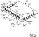
- Fig. 5 is a perspective view taken from the left rear of the first docking unit 200 when it is separated from the second docking unit 300. It should be noted that the one section of the rear edge of the top face of the projection portion 220 is cut away in order to expose the ports, which will be described later.
- the bus signal lines obtained by separation inside the projection portion 220 are passed through to corresponding pins of the second connector 222 provided in the rear face.
- the port signal lines obtained by separation are electrically connected to the corresponding ports provided on the rear face and the side face.
- the first docking unit 200 in this embodiment has an FDD port 231, a cathode ray tube (CRT) (ie video) port 232, a serial port 233, a parallel port 234, a keyboard port 235, and a mouse port 236.
- An external FDD, an external CRT, a modem, a printer, an external keyboard and a mouse can be attached to the respective ports 231, 232, 233, 234, 235 and 236.
- These external devices can be continuously attached to the docking unit 200, regardless of whether the docking unit 200 is coupled with or separated from the notebook computer 100.
- a DC inlet 237 for receiving DC power, and an audio line out 238 for outputting an audio signal are also provided.
- Fig. 6 is a front perspective view of the second docking unit 300 when it is separated from the first docking unit 200. To avoid making the drawing overly complex, various cables and mounted circuits are not illustrated in detail.
- the case of the second docking unit 300 comprises a bottom cover 310 in which various electrical circuits and memory media are accommodated, and a rear cover 320 for covering the rear surface.
- the bottom cover 310 is a shallow-bottom, relatively firm structure.
- An LCD panel 351 for displaying the status of the second docking unit 300 and a bezel 352 that shields the opening for exchanging storage media (mainly, a CD-ROM and a floppy disk) are provided in the front face of the bottom cover 310.
- the left half of the bottom cover 310 is occupied by a power supply circuit 311 that can supply power to the second docking unit 300 itself, the first docking unit 200 and the notebook computer 100. Further, a printed circuit board 312 is secured with screws at the lowermost layer of the right half of the bottom cover 310.
- the room in the front right half of the bottom cover 310 is defined as a "media bay" in which either a CD-ROM drive, an FDD or an HDD can be stored.
- a connector 312a, to which a CD-ROM or an FDD can be connected, and an IDE (Integrated Drive Electronics) connector 312b, to which an HDD can be connected, are mounted at the front of the printed circuit board 312.
- a PC card slot 313 is formed at the rear of the media bay. Two relatively thin cards of types 1/2 or one relatively thick card of type 3, for example, can be inserted into the PC card slot 313.
- a riser card 314 is provided upright at the rear end of the printed circuit board 312. At the rear of the bottom cover 310, a projection portion 340, in which the riser card 314 is inserted, is integrally formed with the bottom cover 310.
- a third connector 321 is attached to the front face of the riser card 314, while various bus slots, such as a PCI slot 322 and an ISA slot 323, a SCSI port 324 and a MIDI port 325, are mounted in the rear face of the riser card 314 (none of which are shown in Fig. 6).
- the third connector 321 is used to receive bus signals passed through from the first docking unit 200.
- the electrical and mechanical specifications of the third connector 321 match those of the second connector 222.
- the bus slots 322 and 323, the SCSI port 324, the MIDI port 325, and the audio line out jack 326 are exposed on the rear face of the second docking unit 300, and a PCI expansion adaptor card, an ISA expansion adaptor card, a SCSI bus and a MIDI device can be connected respectively.
- An extension portion 330 is formed on the right side of the bottom cover 310 and is extended outward from the footprint that is originally a rectangle.
- Interlocking means 332 receives the rotation of a security key 213 from the first docking unit 200.
- a second shutter 333 that can slide forward and backward in response to the transmission means 332, is arranged on the top of the extension portion 330.
- Fig. 7 is a rear view of the first docking unit 200 and the second docking unit 300 when they are coupled together.
- the rear surface of the second docking unit 300 is covered by the rear cover 320. Openings are formed in the rear cover 320 to expose the bus slots 322 and 323, the SCSI port 324 and the MIDI port 325 on the outside.
- the central portion of the projection portion 340 is formed lower.
- the ports 231 through 236 do not mechanically interfere with the case of the second docking unit 300.
- the external devices connected to the ports can continuously remain attached to them, and do not have to be removed each time the docking units are coupled with or separated from each other.
- a port for connecting an audio device and inlet for connecting an AC adapter becomes unnecessary because the second docking unit 300 also has these.
- the DC inlet 237 and the audio line out 238 are therefore shielded by the second docking unit 300.
- the docking units 200 and 300 shown in Figs. 4 and 7 have a security mechanism for protecting a computer system from theft.
- the security mechanism comprises a security key 213; a transmission mechanism accommodated into a security link cover 212; a hook 215 driven by reception of the rotation of the security key 213; a first shutter 216; and a second shutter 333.
- the security mechanism is not the subject of the preset invention, only operations-for the individual sections that are visible externally will be briefly explained here.
- Rotation position (key position) for a security key
- the security key 213 provided to the rear on the right side of the first docking unit 200, as is shown in Fig. 8, there are three key positions: from the right, "eject position", "unlock position” and "lock position".
- the individual key positions correspond to the operating conditions for the devices 100, 200, and 300. More specifically, the eject position is a key position at which the mounted notebook computer 100 is ejected; the unlock position is a key position at which the notebook computer 100 is not locked in place and can be removed from the docking units or can be mounted onto the docking units; and the lock position is a key position at which the removal of the mounted notebook computer 100 and loaded PC cards are inhibited.
- the rotation of the security key 213 is transmitted to the individual sections of the docking units 200 and 300 by the transmission mechanism (not shown) in the link cover 212, so that these sections perform predetermined operations.
- An indicator 223 is located in the top right end of the projection portion 220 to indicate a key position.
- Fig. 9 is shown the status where the security key 213 is placed at the eject position.
- a pair of ejectors 250a and 250b interact and project outward from the right and left front of the projection portion 220.
- the ejectors 250a and 250b abut upon the mounted notebook computer 100 (not shown in Fig. 9) and push it forward.
- a recovery force for returning from the eject position to the unlock position constantly acts on the security key 213.
- the function is provided based on the reasoning that the eject operation should only be performed temporarily, and that the security key 213 must normally be at the unlock position at which a notebook computer 100 can be mounted.
- removal of the security key 213 from the key hole is prevented while it is at the eject position and at the unlock position. Since the security key 213 is always inserted, a plurality of users can share a single docking unit (multi-user environment) .
- the state where the security key 213 is turned so that it is almost vertical is the unlock position.
- the unlocked state is a neutral state between the eject position and the lock position, and while the notebook computer 100 and the PC cards can be freely mounted in this state, nothing prevents them from being removed.
- a hook 215 to inhibit the removal of the notebook computer 100.
- the hook 215 In the unlocked condition, the hook 215 is freely extracted from the notebook computer 100 and is retracted into the mounting portion 210 (see Fig. 10).
- the hook 215 appears outward so that it interlocks with the notebook computer, and the retraction of the hook 215 into the mounting portion 210 is inhibited.
- the hook 215 continues to engage the opening formed in the corresponding opening portion of the bottom of the notebook computer 100, and the removal of the notebook computer 100 is inhibited.
- Another action that accompanies the shift to the lock position is the inhibition of the removal of PC card(s) from the PC card slot of the notebook computer 100.
- the card slot 118 is on the right side and substantially at the rear of the notebook computer 100.
- the first shutter 216 is located upright on the top of the link cover 212 of the first docking unit 200. As is shown in Fig. 12, the first shutter 216 interacts with the rotation of the security key 213 and slides forward and backward.
- the unlock position (A) the first shutter 216 is positioned at the rear (A') and the card slot 118 of the notebook computer 100 is fully opened.
- the lock position (B) the first shutter 216 slides forward and shields at least one part of the card slot 118 (B'). As a result, the removal of the PC card is desirably inhibited.
- An additional action that accompanies the shift to the lock position is the inhibition of the removal of PC card(s) from the PC card slot of the second docking unit 300.
- the second docking unit 300 has the card slot 331 at near the rear on the right side.
- the second shutter 333 is vertically formed near the center of the right side of the second docking unit 300. As is shown in Fig. 12, the second shutter 333 interacts with the rotation of the security key 213, and slides forward and backward.
- the unlock position (A) the second shutter 333 is positioned almost in the center (A') and the card slot 331 of the second docking unit 300 is fully opened.
- the second shutter 333 slides backward and shields at least one part of the card slot 331 (B'). As a result, the removal of a PC card is preferably inhibited.
- a further action that accompanies the shift to the lock position is the inhibition of the separation of the first docking unit 200 and the second docking unit 300. Since the separation of the units is inhibited, peripheral devices (e.g., an HDD, a CD-ROM, and an FDD retained in a media bay) in the docking unit 300 can be protected from being removed accidentally.
- peripheral devices e.g., an HDD, a CD-ROM, and an FDD retained in a media bay
- the removal of the security key 213 is permitted at the lock position. This prevents an unauthorized user from operating the key, and provides physical security.
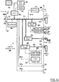
- Fig. 13 is a specific diagram illustrating the internal hardware arrangements of the notebook computer 100 and the first docking unit 200.
- Figs. 14 and 15 are specific diagrams of the internal hardware arrangement of the second docking unit 300. The individual sections will now be described.
- An operating clock is supplied by an oscillator (OSC) 12.
- the CPU 11 is, for example, a "Pentium/lxx MHz" supplied by Intel Corp.
- the CPU 11 is connected with the individual devices across three-layer buses: a processor bus 13 directly connected to the external pins of the CPU 11; a PCI (Peripheral Component Interconnect) bus 17 as a local bus; and an ISA (Industry Standard Architecture) bus 35 as an input/output bus.
- PCI Peripheral Component Interconnect
- ISA Industry Standard Architecture
- the design of the bridge circuit 14 in this embodiment provides for the inclusion of a memory controller for controlling access to a main memory 15, and a data buffer for absorbing a gap of data transfer rate between the buses 13 and 17.
- An L2-cache 16 is composed of a memory device, such as an SRAM, that can be accessed at high speed, and is employed to save the minimum required data in order to absorb a difference between the processing speed of the CPU 11 and the accessing speed to the main memory 15.
- a ROM 18 is a nonvolatile memory in which are stored control code for hardware operation (BIOS) and a test program executed at the time of powered on (power on self-test or POST).
- the PCI bus 17 is a high speed bus originally proposed by Intel Corp. Its primary performance specifications are a bus width of 32 bits, an operating frequency of 33 MHz, and a highest transfer speed of 132 Mbps. Another feature of the PCI is that it can be mutually connected to another independently driven bus by a bridge circuit (for example, blocks 22, 23 or 365).
- the PCI bus 17 communicates with devices, such as a graphic controller 19 and a CardBus controller 20, for which relatively fast data transfer is required.
- the graphic controller 19 is a peripheral controller that actually processes a drawing command from the CPU 11.
- the graphic controller 19 temporarily writes the processed image data in a screen buffer (VRAM) 21, and thereafter reads the image data from the VRAM 21 and outputs it to a liquid crystal display (LCD) 125 that is provided as a standard feature.
- the graphic controller 19 can employ an attached DA converter to convert a video signal into an analog signal.
- An analog video signal is output to a CRT port 41 across a signal line 19a.
- the signal line 19a is branched on route and also forwards signals to the docking connector 130.
- the CardBus controller 20 transmits bus signals across the PCI bus 17 to the PC card slot 118.
- a PC card that conforms to the "PC Card Specification 95" and that can be driven at high speed is inserted into the card slot 118.
- a bridge circuit (PCI-PCI bridge) 22 is provided at the rear end of the PCI bus 17.
- the bridge circuit 22 is employed for data exchange between the PCI bus 17 and a local (secondary) PCI bus 371 (i.e., the bus of the second docking unit 300).
- the bridge circuit 22 disables the signal pins of the local side when there is no PCI bus provided for the local side.
- the PCI bus 17 and the ISA bus 35 are mutually connected by a bridge circuit (PCI-ISA bridge) 23.
- the bridge circuit 23 in this embodiment includes a DMA controller, a programmable interrupt controller (PIC), and a programmable interval timer (PIT).
- the bridge circuit 23 also includes an IDE interface for connecting a hard disk drive (HDD) (originally, the IDE was the standard employed for connecting an HDD directly to an ISA bus).
- An IDE_HDD 24a and an incorporated IDE_CD-ROM 24b, which are installed as standard features, are connected to the IDE interface.
- the two bridge circuits, 14 and 23, conform to the PCI standard, and generally are available as a single-chip set. For example, one such chip set is "Triton", supplied by Intel Corp.
- the ISA bus 35 communicates with devices for which relatively low speed data transfer is satisfactory: an I/O controller 25, a keyboard/mouse controller (KMC) 26, and a digital signal processor (DSP) 27.
- I/O controller 25 I/O controller 25
- KMC keyboard/mouse controller
- DSP digital signal processor
- the I/O controller 25 accesses a floppy disk drive (FDD) 28 and controls serial and parallel data input/output with an external device, for example, a modem or a printer (neither of them shown).
- An FDD signal line 25a is directed to an incorporated FDD 28, and is also branched and extended to the docking connector 130.
- a serial signal line 25b is directed to a serial port 45 on the rear surface of the case of the notebook computer 100, and is also branched and extended to the docking connector 130.
- a parallel signal line 25c is directed to a parallel port 46, and is also branched and extended to the docking connector 130. It should be noted that since the volume of the notebook computer 100 is limited, only one of the FDD 28 and the IDE_CD-ROM 24b can be accommodated in the media bay at any given time.
- the KMC 26 controls data input/output at a keyboard or with a mouse or a Track Point ("Track Point" is a trademark of IBM Corp.).
- a mouse signal line 26a and a keyboard signal line 26b are directed respectively to a mouse port 43 and a keyboard port 44, and are also branched and extended to the docking connector 130.
- the DSP 27 is a dedicated processor for handling digital signals and is employed primarily for audio data processing.
- the DSP 27 can also process MIDI (Musical Instrument Digital Interface) data.
- a MIDI signal line 27a is assigned to one part of the docking connector 130.
- An audio output signal line 27b is directed to an audio line out 42, and is also branched and extended to the docking connector 130.
- An analog switch 30 is used to connect the rear end of the ISA bus 35 to the docking connector 130 and to separate it therefrom.
- the analog switch 30 renders the rear end of the ISA bus 35 on to electrically connect the bus 35 to a corresponding pin of the docking connector 130, or renders the ISA bus 35 off to separate the bus 35 from the docking connector 130.
- the analog switch 30 is controlled by the bridge circuit 22.
- the bridge circuit 22 drives the local bus pin and the analog switch 30 renders the ISA bus 35 off.
- the bridge circuit 22 When the ISA bus is directly connected to the peripheral side via the docking connector 130 (Fig. 15; which will be described later), the bridge circuit 22 renders the local bus pin off, and the analog switch 30 renders it on. In other words, only one of the PCI bus 17 and the ISA bus 35 is assigned for the docking connector 130 at any given time.
- a DC-DC converter 31 reduces a DC voltage supplied via the DC inlet 47 or the docking connector 130, and stably supplies power to the individual devices in the notebook computer 100.
- the PCI bus 17, the ISA bus 35, the branched port signal lines 25a, 25b, 25c, 26a, 26b, ..., and power feed lines 31a are collected together into one bundle.
- the connector pins in the docking connector 130 are assigned for these collected signal lines and power feed lines.
- the mechanical and electrical specifications for the docking connector 130 match those of the first connector 221 of the first docking unit 200.
- Line segment P-P' corresponds to the rear surface of the case of the notebook computer 100.
- the docking connector 130 and the other ports 41 through 47, which are not collected at the connector 130, are mostly arranged in an area that corresponds to line segment P-P'. While the notebook computer 100 is not coupled with the first docking unit 200, the rear portion P-P' is exposed outward and the ports 41 through 47 can be connected with corresponding external devices, for example, an external CRT display, an external keyboard, etc., which are not shown. On the other hand, while the notebook computer 100 is docked to the first docking unit 200, the rear portion P-P' is closely attached to the front face of the projection portion 220 so that the docking connector 130 is attached to the first connector 221 both mechanically and electrically. Although the other ports 41 through 47 are shielded and can not be used due to this docking, they are replicated by the first docking unit 200.
- the particular hardware structure of the notebook computer 100 is not directly relevant to the present invention.
- two-layer buses comprising a PCI bus and an ISA bus are not necessarily provided; likewise a function that alternatively connects either the PCI bus or the ISA bus to the docking connector 130 is not necessary. Rather only one bus may be fixedly connected to the docking connector 130.
- the minimum requirement for the notebook computer 100 as regards the present invention is simply that it provides a docking connector 130 that can be matched to the electrical and mechanical specifications of the first connector 221.
- the mechanical and electrical specifications for the first connector 221 of the first docking unit 200 match those of the docking connector 130.
- a signal line bundle 260 that has been received collectively through the first connector 221 is branched to bus signal lines (PCI bus or ISA bus) 260a, an audio output signal line 260b, a power feed line 260c, an FDD signal line 260e, a CRT signal line 260f, a serial signal line 260g, a parallel signal line 260h, a keyboard signal line 260i, and a mouse signal line 260j.
- These branched bus and port signal lines are directed respectively to the second connector 222, the audio line out 238, the DC inlet 237, the FDD port 231, the CRT port 232, the serial port 233, the parallel port 234, the keyboard port 235, and the mouse port 236.
- the second connector 222, and the DC inlet 237 and the audio line out 238 are arranged in a portion indicated by line segment Q-Q'.
- the portion corresponding to the line segment Q-Q' is closely attached to the second docking unit 300 when the docking units 200 and 300 are coupled together.
- the second connector 222 is mechanically and electrically connected to the third connector 321 of the second docking unit 300.
- the DC inlet 237 and the audio line out jack 238 are shielded by the docking and can not be used. This is because while the docking units 200 and 300 are coupled together power is supplied from the second docking unit 300, and the audio line out is replicated by the second docking unit 300 and becomes unnecessary.
- the FDD port 231, the CRT port 232, the serial port 233, the parallel port 234, the keyboard port 235, and the mouse port 236 are located in the surface of the case indicated by line segment R-R'.
- the R-R' portion corresponds to an area that does not mechanically contact the second docking unit 300, even when the both docking units are coupled together. Therefore, external devices, such as an external FDD, an external CRT display, a modem, a printer, an external keyboard, and an external mouse (none which are shown), connected to the ports can be continually attached to the docking unit 200, regardless of whether it is coupled with the second unit 300 or is separated therefrom. In other words, the connection of the cable to these ports can be totally managed only by the first docking unit 200.
- Second docking unit 300
- the second docking unit 300 shown in Fig. 14 is a PCI bus expansion type.
- the second docking unit 300 has the third connector 321 of which the electrical and the mechanical specifications match those of the second connector 222, and collectively receives a bus signal and port signals through the third connector 321.
- a CPU 360 is a processor for controlling the operations of the individual sections in the second docking unit 300 especially when docking with or undocking from the notebook computer 100.
- the docking and undocking during a normal operational mode or a power management mode can be performed by the CPU 360 communicating with the CPU 11 in the notebook computer 100.
- the "hot docking” and the “warm docking” are not related to the subject of the present invention, and will not be explained further here.
- the CPU 360 drives an eject lock 361 which electrically inhibits the removal of the notebook computer 100, a beeper 362 for generating an alarm sound at the time of docking and undocking, and an LCD panel 351 for indicating the state of the second docking unit 300.
- An EEPROM 380 is a nonvolatile memory whose contents can be electrically erased and reprogrammed.
- the EEPROM 380 is used to store a minimum amount of data, such as the serial product number of the docking unit 300, the password and system configuration data required, for security during docking and undocking and for guaranteeing the operation of the system.
- the stored contents can be read by the CPU 360 and by the CPU 11 of the notebook computer 100.
- An AC/DC adaptor 311 rectifies and smoothes an alternating current voltage supplied from an external AC power source (e.g., a commercially available mains power source) to produce a predetermined direct current driving voltage.
- the AC/DC adaptor 311 receives power from an outside power source through an AC inlet 368.
- a power feed line 311a is collected into a bus 371, which is directed to the third connector 321.
- a MIDI port 325 is a port for fetching MIDI data from an external MIDI device.
- a MIDI signal line 325a is connected to the bus 371 and is directed to the third connector 321.
- An audio output signal line 326a of the third connector 322 is branched from the bus 371 and is directed to an audio line out jack 326.
- An FDD signal line 367a of the third connector 322 is branched from the bus 371 and is directed to the connector 312a (see Fig. 6). An FDD 367 can be connected through the connector 312a.
- the PCI bus 371 extended into the second docking unit 300 communicates with the devices for which relatively high speed data transfer is required: a CardBus controller 363 and a SCSI (Small Computer System Interface) controller 364.
- the PCI bus slot 322 is formed at the rear end of the PCI bus 371.
- a PCI expansion adaptor card can be inserted into the PCI bus slot 322.
- the SCSI controller 364 performs protocol conversion between the PCI bus 371 and a SCSI bus 364a, which is located outside, via the SCSI port 324.
- a maximum of eight SCSI devices can be connected to the SCSI port 324 by using a daisy chain.
- the SCSI devices are, for example, an HDD, a CD-ROM drive, and an MO disk drive.
- the second docking unit 300 further includes an ISA bus 372.
- An ISA bus slot 323 is provided at the rear end of the ISA bus 372 for attaching an ISA expansion adaptor card. The purpose allowing for expansion of the ISA bus is be able to exploit the rich ISA legacy of devices, etc.
- the PCI bus 371 and the ISA bus 372 are mutually connected by a bridge circuit (PCI-ISA bridge) 365.
- the structure of the bridge circuit 365 is almost the same as the hardware block 23, and also has an IDE interface.
- An HDD, a CD-ROM, or other IDE device can be attached to the IDE interface.
- the second docking unit 300 in this embodiment because of the limitation placed on its volume, only one of the FDD 367 and the IDE device (the HDD or the CD-ROM) 366 can be accommodated in the media bay.
- the bus slots 322, 323, the card slot 331, the ports 324 and 325, and the AC inlet 368 are formed in the surface (line segment S-S' in Fig. 14) of the case of the second docking unit 300.
- Fig. 15 is a specific diagram illustrating the internal hardware arrangement of another second docking unit 300'.
- the second docking unit 300' is so designed that only an ISA bus 372 is expanded, instead of an PCI bus.
- the docking unit 300' does not have a bridge circuit (PCI-ISA bridge) and a PCI bus slot.
- PCI-ISA bridge PCI-ISA bridge
- PCMCIA Personal Computer Memory Card International Association
Abstract
Description
- The present invention relates to a so-called docking unit for a portable computer, that is mechanically coupled with and is electrically connected to the portable computer to expand the peripheral environment of the portable computer. Such a docking unit can be constituted more easily with the selected functions required by a user.
- As a consequence of current developments. various types of personal computers, such as desktop and notebook types, have been produced and are available on the market. Of these computers, the notebook computers are battery-operable personal computers for which portability is a design consideration.
- Since compact size and light weight are important notebook computer features, expansion of these computers by adding peripheral devices internally is not possible as no extra space is available, and device expansion using merely a PC Card can not sometimes provide a viable alternative. Furthermore, as the exterior dimensions of a notebook computer ensure but a small surface area, only a very limited number of bus slots can be provided. So that while it is not too uncommon for desktop computers to have ten or more bus slots, ordinarily, no bus slots, or one or two at the most, are provided for laptop and notebook computers. And as for a notebook computer portability is the most important feature, having to attach or detach a cable (e.g., a printer cable, a monitor cable, a communication cable) each time a notebook computer is used, whether in or outside an office, is a very complicated task that adversely affects the usability of the unit.
- The employment of a so-called "Docking station" (also called an "expansion box" or an "expansion unit"), when a notebook computer is used in an office, makes it possible to provide with a notebook computer the same working environment as that of a desktop computer, while at the same time not adversely affecting portability. The primary functions of a docking station are "Port Replication" and "Bus Expansion". Port replication is realized by providing a docking station with connection ports for notebook computer expansion. In other words, when a cable has been connected to each port of a docking station in advance, a user need only dock a notebook computer in the docking station to immediately secure the use of a printer, an external monitor, and a network. From the point of view that all cable connections are managed by it, the port replication function is also called a "cable management" function. On the other hand, the bus expansion function is realized by a docking station possessing the capability to expand the bus in a notebook computer, and having at least one bus slot. By docking a notebook computer in a docking station, it is possible for a user to employ desired adaptor cards and devices via the docking station. In other words, no special limitations are placed on the user of a notebook computer.
- A docking station is disclosed in, for example, the specifications for Japanese Patent Application No. Hei 05-181593 (Internal docket No.: JA9-93-027; European application 943053800.1), and in Japanese Patent Application No. Hei 06-134124 (Internal docket No.: JA9-94-030; European application 95304122.5), both of which are assigned to the present applicant.
- In Fig. 16 are shown a
typical notebook computer 100 anddocking station 200. At the rear, thenotebook computer 100 has a connector for use when docking (hereinafter referred to as a "docking connector"; not shown in Figure 16). The docking connector generally consists of several tens to several hundreds of connector pins, with each connector pin being assigned for a port signal line or a bus signal line in thenotebook computer 100. The bus that thenotebook computer 100 allocates for the docking connector (i.e., the bus for which expansion is desired) is normally an ISA (Industry Standard Architecture) bus, which is a standard input/output bus. This is because the ISA bus has long been the de facto standard in this field, and there is a very wide range of available ISA devices and ISA applications. In addition, among some of the latest notebook computers, instead of an ISA bus, a PCI (Peripheral Component Interconnect) bus, positioned as a local bus of a CPU, is assigned to a docking connector. In other words, the PCI bus is expanded. This seems to have occurred for the following reasons: the number of devices, such as graphics and PC cards, that require high speed data transfer has increased; expansion of the PCI bus is easy since a number of devices connectable to a single PCI bus is limited; and each bus can be electrically stably expanded by means of a PCI bridge circuit. - The
docking station 200 comprises a main body that incorporates electric circuitry; a mounting portion whereat thenotebook computer 100 is mounted on the top surface of the main body; and a projection portion that projects upward from the rear end of the mounting portion. A connector is provided on the front surface of the projection portion to engage a docking connector provided on the rear surface of thenotebook computer 100. The surface of the connector may be covered with a lid freely opened and closed in order to protect the connector when it is not used. A pair of linear protrusions are so formed along both sides of the mounting portion. A notebook computer is guided along these linear protrusions when it is being mounted. - The forms of the docking stations vary, and range from relatively small ones that have only a port replication function, to relatively large ones that can afford to provide a plurality of storage spaces (also called "media bays") in which fixed or detachable memory devices (hard disk drives (HDDs), floppy disk drives (FDDs), compact disk read only memory (CD-ROM) drives, etc.) can be accommodated, and that can provide at least one bus slot for inserting an adaptor card. However, all the types of docking stations have essentially the following shortcomings.
- (1) Product lineups for the docking stations must, in respect to their capabilities and the number of devices that can be expanded, correspond to the number of docking connector types (N) and the number of configuration types (M). Therefore, a manufacturer must develop and produce N x M types of products and must also carry these types as inventories. Since configurations also differ, depending on whether a expanded bus is a PCI bus or an ISA bus, the number of product types is accordingly increased.
- (2) A user selects and purchases a docking station having a desired configuration from among those with electrical and mechanical specifications that match the specifications for the docking connector on the user's notebook computer. As time passes and when the user needs to increase the expansion capabilities of a bus or to alter the configuration, the user must purchase another docking station. Furthermore, a notebook computer that expands the ISA bus can not be operated with a docking station for the PCI bus. And conversely, a notebook computer that expands the PCI bus can not be operated with a docking station for an ISA bus. A connector and its peripheral portion configured for mechanical and electrical coupling with a notebook computer substantially conform to the product specifications, such as the form factor for the notebook computer, and may not be interchangeably applied. Thus, it could happen that when a new notebook computer is purchased, a docking station must be changed accordingly.
- A moderate solution for the problem can be proposed whereby the bus expansion function of a docking station is augmented in anticipation of the up-grading of a system configuration in the future, that is, an extra bus slot and a media bay are provided. However, when a function that will be employed by only a limited number of persons under specific conditions is provided as a standard feature of a product, the expense to users is increased.
- Typically, in an office (or a workshop) a plurality of users (multi-users) who use a docking station alternately connect the respective notebook computers to it. Within the same office, however, the notebook computers employed by users will represent a variety of types, such as PCI bus expansion types and ISA bus expansion types. Thus, if the expanded bus type of the docking station is fixed, it is difficult to realize a multi-user environment.
- The port replication function of the docking station has more commonality with each other than the bus expansion function. Therefore, it is very wasteful to exchange an entire docking station only because the configuration of the bus expansion function does not match the perceived need.
- Accordingly, the invention provides a docking station, adapted to receive a portable computer, comprising:
- (a) a first docking unit, which can be mechanically coupled with said portable computer, including a first connector for electrically connecting with said portable computer, a plurality of connection ports provided for the respective port signal lines that run from said first connector, and a second connector for directly passing through bus signal lines that run from said first connector; and
- (b) a second docking unit, which can be mechanically coupled with said first docking unit, including a third connector for electrically connecting with said second connector.
- In a preferred embodiment, said second docking unit further includes space for retaining a peripheral device connected to a bus expanded through said third connector, and at least one bus slot to connect an expansion adaptor card to said bus expanded through said third connector.
- In a typical environment, said connection ports include at least one of an FDD port, a CRT port, a serial port, a parallel port, a keyboard port and a mouse port, and said bus signal lines are PCI bus signal lines or ISA bus signal lines.
- The invention also provides a docking unit adapted to receive a portable computer, comprising: a mounting portion on which said portable computer is mounted; a first connector for electrically connecting with said portable computer; a plurality of connection ports provided for port signal lines that run from said first connector; and a second connector for directly passing through bus signal lines that run from said first connector.
- The invention further provides a docking unit, that can be coupled with and removed from the above-described docking unit, comprising: a third connector for electrically connecting with said second connector; space for retaining a peripheral device connected to a bus expanded through said third connector; and at least one bus slot for connecting an expansion adaptor card to said bus expanded via said third connector.
- This approach provides a docking station or unit for a portable computer that can be mechanically coupled with and electrically connected to a portable computer to expand the functions of the portable computer. The station or unit can be designed to incorporate selected functions required by a user.
- Various embodiments of the invention will now be described in detail by way of example only, with reference to the following drawings:
- Fig. 1 is a conceptual diagram illustrating a docking unit for a personal computer, in particular showing the notebook computer and a first docking unit;
- Fig. 2 is a high-level block diagram illustrating one mode of a
second docking unit 300, of a PCI bus expansion type; - Fig. 3 is a high-level block diagram illustrating another mode of the
second docking unit 300, of an ISA bus expansion type; - Fig. 4 is a perspective view of the exterior of a docking unit for a portable computer according to one embodiment of the present invention;
- Fig. 5 is an upper left rear perspective view of the
first docking unit 200 when it is separated from thesecond docking unit 300; - Fig. 6 is a front perspective view of the
second docking unit 300 when it is separated from thefirst docking unit 200; - Fig. 7 is a rear view of the
first docking unit 200 and thesecond docking unit 300 when they are coupled together; - Fig. 8 is a diagram showing key positions for a
security key 213; - Fig. 9 is a diagram showing the state where the
security key 213 is placed at the eject position; - Fig. 10 is a diagram showing the condition where a
hook 215 on the top of a mountingportion 210 is manipulated; - Fig. 11 is a diagram showing the state where the
hook 215 engages thenotebook computer 100; - Fig. 12 is a diagram showing the condition where a
first shutter 216 inhibits the removal of a PC card from thenotebook computer 100, and where asecond shutter 333 inhibits the removal of a PC card from thesecond docking unit 300; - Fig. 13 is a diagram illustrating the internal hardware arrangements of a
notebook computer 100 and afirst docking unit 200; - Fig. 14 is specific diagram illustrating the internal hardware arrangement of one embodiment of a
second docking unit 300; - Fig. 15 is a specific diagram illustrating the internal hardware arrangement of another embodiment of
second docking unit 300; and - Fig. 16 is a diagram illustrating a typical mode of a docking station.
- Figs. 1 through 3 are high-level conceptual diagrams illustrating a notebook computer and associated docking station. A docking station in accordance with the present invention comprises a
first docking unit 200 and asecond docking unit 300. - A
notebook computer 100 incorporates a printed circuit board (not shown) that mounts a CPU, a main memory, and various other electric circuits. Various port signal lines and bus signal lines extended from the printed circuit board are collected and appear externally as adocking connector 130. The port signal lines here are, for example, a serial signal line, a parallel signal line, and a video signal line. The kinds of port signal lines extended to the exterior are relatively common to all notebook computer types. On the other hand, depending on the computer model, bus signal lines allocated for thedocking connector 130 varies. That is, the expanded bus may be, for example, the ISA bus, or a local bus such as the PCI bus. The types and the number of peripheral devices desired to be connected to the expanded the bus, i.e., the configuration of the docking station, varies in accordance with the needs of users, and a common configuration that will suffice for all the types of notebook computers is difficult to define. - The
first docking unit 200 has a mechanism by which it can be coupled with and separated from thenotebook computer 100. Thedocking unit 200 has afirst connector 221 that physically engages thedocking connector 130 of thenotebook computer 100 and has matched electrical specifications. Thefirst connector 221 collectively receives port signal lines and bus signal lines from thenotebook computer 100 through thedocking connector 130. The signal lines in thefirst connector 221 are again divided into the port signal lines and the bus signal line inside thedocking unit 200. The port signal lines are electrically connected to the corresponding ports that are provided on the surface of the case of thedocking unit 200. The ports are, for example, a serial port, a parallel port, and a CRT port. The bus signal lines obtained by division pass through directly to asecond connector 222. Thesecond docking unit 300 has only one function, from among the functions required for a docking station, that is relatively common to users. Thus, thesecond docking unit 300 can be defined as the minimum required docking station. From another point of view, thefirst docking unit 200 absorbs the form factor of thenotebook computer 100 and the differences in the mechanical and the electrical specifications between the docking connectors so as not to affect thesecond docking unit 300. The ports and thesecond connector 222 are arranged on the surface opposite thefirst connector 221. - The
second docking unit 300 supplements a function, from among the functions required for the docking station, for which the need is not very common among users (or among notebook computers). The product lineups for thesecond docking unit 300 vary, and the configuration differs greatly depending on, for example, which bus in thenotebook computer 100 is to be expanded. - Fig. 2 is a schematic diagram illustrating one mode of the
second docking unit 300, i.e., the hardware arrangement of adocking unit 300 of a PCI bus expansion type. Thesecond docking unit 300 has athird connector 321 that physically engages thesecond connector 222 of thefirst docking unit 200 and has matched electrical specifications. Thesecond docking unit 300 internally includes a bay for accommodating various peripheral devices, a PCI bus received through thethird connector 321, and an ISA bus connected to the PCI bus by a bridge circuit. In the bay can be accommodated at least one PCI device connected to the PCI bus, or at least one ISA device connected to the ISA bus. The end of the PCI bus is electrically connected to aPCI bus slot 322 that is provided on the surface of the case of thesecond docking unit 300. The end of the ISA bus is electrically connected to anISA bus slot 323 provided on the surface of the case of thesecond docking unit 300. - Fig. 3 is a schematic diagram illustrating another example of the
second docking unit 300, i.e., the hardware arrangement for adocking unit 300 of an ISA bus expansion type. Thesecond docking unit 300 has athird connector 321 that physically engages asecond connector 222 of afirst docking unit 200, and has matched electrical specifications. Thesecond docking unit 300 internally includes a bay for storing various peripheral devices and an ISA bus received through thethird connector 321. At least one ISA device connected to the ISA bus is accommodated in the bay. The end of the ISA bus is electrically connected to anISA bus slot 323 provided on the surface of the case of thesecond docking unit 300. - As was previously described, the need for the bus expansion function of a docking station is not common to all users compared to the need for the port replication function. The connector for coupling the docking unit with the notebook computer and its peripheral portion depend greatly on the product standards, such as the form factor of the notebook computer, and can not cope with many applications. Therefore, in accordance with the present invention, a unit for the port replication function for directly connecting with a notebook computer is provided separately from a unit for the bus expansion function for which the need varies. Thus, when a user desires to alter or expand the expanded contents, he or she has only to change the second docking unit while retaining the port replication function unit, i.e., the first docking unit. When the notebook computer is replaced with a new one, only the first docking unit need be changed while the second docking unit can be retained.
- So long as the mechanical and electrical specifications for the docking connector and the first, the second and the third connectors match with each other, the first docking unit can be coupled with many types of second docking unit. Thus, a manufacturer need develop and produce only M + N types of docking units, where M denotes the number of configuration types, such as the contents and the number of devices that can be expanded, and N denotes the number of connector types for notebook computers. In other words, the load that is incurred by the preparation of various product types and the need to carry inventory on hand can be drastically reduced.
- Fig. 4 is a diagram illustrating the external appearance of a notebook computer and a docking station in accordance with one embodiment of the present invention. The docking station comprises two independent units that can be physically coupled with and separated from each other: a
first docking unit 200 and asecond docking unit 300. - A
notebook computer 100 is a personal computer that comprises a shallow-bottommain body 110 and alid 120 pivotally attached almost at the rear edge of themain body 110. The footprint of thenotebook computer 100 is, for example, A4 size. Generally, akeyboard unit 115 is mounted on the top surface of themain body 110, and a liquid crystal display (LCD) 125 is fitted inside the inner face of thelid 120. - Usually, a docking connector 130 (not shown) is provided on the rear face of the notebook computer. Also, formed in the bottom face are a pair of linear grooves (not shown) into which a pair linear protrusions (which will be described later) are to be inserted and guided along, and an opening (not shown) for engaging a hook 215 (which will be described later) on the
first docking unit 200. Further, acard slot 118 is formed in the right side of thenotebook computer 100, so that a PC card can be detached and exchanged. - One example of such a
notebook computer 100 is the "ThinkPad 760" ("ThinkPad" is a trademark of IBM Corporation) available from IBM Corporation. It should be noted that the structure of the notebook computer is not the subject of the present invention. - The
first docking unit 200 comprises a mountingportion 210 on which, as a portable computer, thenotebook computer 100 is mounted, and aprojection portion 220 projecting rearward of the mountingportion 210. - The mounting
portion 210 is a thin and rigid structure that has a width and a depth correspond to the footprint of thenotebook computer 100. A side wall 211 is defined at the left end of the mountingportion 210, while asecurity link cover 212 is provided on the right end. Thesecurity link cover 212 is a member that covers and hides a transmission mechanism (not shown) that transmits the rotations of asecurity key 213 to the individual sections. The transmission mechanism is employed to set thedocking units security key 213 is transmitted to, for example, thehook 215 provided near the front of the mountingportion 210; afirst shutter 216 provided upright on the top of thesecurity link cover 212; and asecond shutter 333 provided perpendicularly on the right side of the second docking unit 300 (which will be described later). - An interval between the side wall 211 and the internal wall of the
link cover 212 is substantially equivalent to the width of thenotebook computer 100. A pair oflinear protrusions 214a and 214b protrude upward along the right and the left side of the top face of the mountingportion 210, and maintain a predetermined interval. When thenotebook computer 100 is to be mounted on thefirst docking unit 200 as indicated by the chained line in Fig. 4, the direction of movement of thenotebook computer 100 is restricted by the side wall 211 and the inner wall of thelink cover 212, and thenotebook computer 100 is guided along thelinear protrusions 214a and 214b and can smoothly be attached. - A
first connector 221 is provided on the right front surface of theprojection portion 220 provided at the rear of thedocking unit 300, and employed for connection to thenotebook computer 100. The electrical and mechanical specifications of thefirst connector 221 match those of thedocking connector 130 of thenotebook computer 100. Thefirst connector 221 consists of, for example, 240 pins, and includes various port signal pins and bus signal pins. - Electrical circuits (not shown) are mounted inside the
projection portion 220. The electrical circuits mainly separate the signal pins of thefirst connector 221 into the port signal pins and the bus signal pins. The signal pins are separated in this manner because thefirst docking unit 200 performs the port replication function, and the bus expansion function is performed by thesecond docking unit 300. - Fig. 5 is a perspective view taken from the left rear of the
first docking unit 200 when it is separated from thesecond docking unit 300. It should be noted that the one section of the rear edge of the top face of theprojection portion 220 is cut away in order to expose the ports, which will be described later. - The bus signal lines obtained by separation inside the
projection portion 220 are passed through to corresponding pins of thesecond connector 222 provided in the rear face. The port signal lines obtained by separation are electrically connected to the corresponding ports provided on the rear face and the side face. Thefirst docking unit 200 in this embodiment has anFDD port 231, a cathode ray tube (CRT) (ie video)port 232, aserial port 233, aparallel port 234, akeyboard port 235, and amouse port 236. An external FDD, an external CRT, a modem, a printer, an external keyboard and a mouse (none of which are shown) can be attached to therespective ports docking unit 200, regardless of whether thedocking unit 200 is coupled with or separated from thenotebook computer 100. ADC inlet 237 for receiving DC power, and an audio line out 238 for outputting an audio signal are also provided. - Fig. 6 is a front perspective view of the
second docking unit 300 when it is separated from thefirst docking unit 200. To avoid making the drawing overly complex, various cables and mounted circuits are not illustrated in detail. - The case of the
second docking unit 300 comprises abottom cover 310 in which various electrical circuits and memory media are accommodated, and arear cover 320 for covering the rear surface. - The
bottom cover 310 is a shallow-bottom, relatively firm structure. AnLCD panel 351 for displaying the status of thesecond docking unit 300 and abezel 352 that shields the opening for exchanging storage media (mainly, a CD-ROM and a floppy disk) are provided in the front face of thebottom cover 310. - The left half of the
bottom cover 310 is occupied by apower supply circuit 311 that can supply power to thesecond docking unit 300 itself, thefirst docking unit 200 and thenotebook computer 100. Further, a printedcircuit board 312 is secured with screws at the lowermost layer of the right half of thebottom cover 310. - The room in the front right half of the
bottom cover 310 is defined as a "media bay" in which either a CD-ROM drive, an FDD or an HDD can be stored. A connector 312a, to which a CD-ROM or an FDD can be connected, and an IDE (Integrated Drive Electronics) connector 312b, to which an HDD can be connected, are mounted at the front of the printedcircuit board 312. - A PC card slot 313 is formed at the rear of the media bay. Two relatively thin cards of types 1/2 or one relatively thick card of type 3, for example, can be inserted into the PC card slot 313.
- A
riser card 314 is provided upright at the rear end of the printedcircuit board 312. At the rear of thebottom cover 310, aprojection portion 340, in which theriser card 314 is inserted, is integrally formed with thebottom cover 310. Athird connector 321 is attached to the front face of theriser card 314, while various bus slots, such as aPCI slot 322 and anISA slot 323, aSCSI port 324 and aMIDI port 325, are mounted in the rear face of the riser card 314 (none of which are shown in Fig. 6). Thethird connector 321 is used to receive bus signals passed through from thefirst docking unit 200. The electrical and mechanical specifications of thethird connector 321 match those of thesecond connector 222. Thebus slots SCSI port 324, theMIDI port 325, and the audio line outjack 326 are exposed on the rear face of thesecond docking unit 300, and a PCI expansion adaptor card, an ISA expansion adaptor card, a SCSI bus and a MIDI device can be connected respectively. - An
extension portion 330 is formed on the right side of thebottom cover 310 and is extended outward from the footprint that is originally a rectangle. Acard slot 331, for exchanging a PC card, is formed in the surface of theextension portion 330. Interlocking means 332 receives the rotation of asecurity key 213 from thefirst docking unit 200. Asecond shutter 333, that can slide forward and backward in response to the transmission means 332, is arranged on the top of theextension portion 330. - Fig. 7 is a rear view of the
first docking unit 200 and thesecond docking unit 300 when they are coupled together. - The rear surface of the
second docking unit 300 is covered by therear cover 320. Openings are formed in therear cover 320 to expose thebus slots SCSI port 324 and theMIDI port 325 on the outside. - The central portion of the
projection portion 340 is formed lower. When thefirst docking unit 200 is coupled with thesecond docking unit 300, therefore, theports 231 through 236 do not mechanically interfere with the case of thesecond docking unit 300. Thus, the external devices connected to the ports can continuously remain attached to them, and do not have to be removed each time the docking units are coupled with or separated from each other. When the docking units are coupled together, a port for connecting an audio device and inlet for connecting an AC adapter becomes unnecessary because thesecond docking unit 300 also has these. TheDC inlet 237 and the audio line out 238 are therefore shielded by thesecond docking unit 300. - The
docking units security key 213; a transmission mechanism accommodated into asecurity link cover 212; ahook 215 driven by reception of the rotation of thesecurity key 213; afirst shutter 216; and asecond shutter 333. As the security mechanism is not the subject of the preset invention, only operations-for the individual sections that are visible externally will be briefly explained here. - For the
security key 213 provided to the rear on the right side of thefirst docking unit 200, as is shown in Fig. 8, there are three key positions: from the right, "eject position", "unlock position" and "lock position". The individual key positions correspond to the operating conditions for thedevices notebook computer 100 is ejected; the unlock position is a key position at which thenotebook computer 100 is not locked in place and can be removed from the docking units or can be mounted onto the docking units; and the lock position is a key position at which the removal of the mountednotebook computer 100 and loaded PC cards are inhibited. The rotation of thesecurity key 213 is transmitted to the individual sections of thedocking units link cover 212, so that these sections perform predetermined operations. Anindicator 223 is located in the top right end of theprojection portion 220 to indicate a key position. - In Fig. 9 is shown the status where the
security key 213 is placed at the eject position. - As the
security key 213 is rotated clockwise from the unlock position, a pair ofejectors projection portion 220. Theejectors - A recovery force for returning from the eject position to the unlock position constantly acts on the
security key 213. The function is provided based on the reasoning that the eject operation should only be performed temporarily, and that thesecurity key 213 must normally be at the unlock position at which anotebook computer 100 can be mounted. In addition, while taking into consideration that the key operation is required for conditions other than the locked condition, removal of thesecurity key 213 from the key hole is prevented while it is at the eject position and at the unlock position. Since thesecurity key 213 is always inserted, a plurality of users can share a single docking unit (multi-user environment) . - The state where the
security key 213 is turned so that it is almost vertical is the unlock position. The unlocked state is a neutral state between the eject position and the lock position, and while thenotebook computer 100 and the PC cards can be freely mounted in this state, nothing prevents them from being removed. - When the
security key 213 is further rotated counterclockwise from the unlock position to the lock position, thedocking units - One action that accompanies the shift to the lock position involves the employment of a
hook 215 to inhibit the removal of thenotebook computer 100. In the unlocked condition, thehook 215 is freely extracted from thenotebook computer 100 and is retracted into the mounting portion 210 (see Fig. 10). However, when thesecurity key 213 is turned to the lock position, thehook 215 appears outward so that it interlocks with the notebook computer, and the retraction of thehook 215 into the mountingportion 210 is inhibited. As a result, as is shown in Fig. 11, thehook 215 continues to engage the opening formed in the corresponding opening portion of the bottom of thenotebook computer 100, and the removal of thenotebook computer 100 is inhibited. - Another action that accompanies the shift to the lock position is the inhibition of the removal of PC card(s) from the PC card slot of the
notebook computer 100. As was previously described, thecard slot 118 is on the right side and substantially at the rear of thenotebook computer 100. Thefirst shutter 216 is located upright on the top of thelink cover 212 of thefirst docking unit 200. As is shown in Fig. 12, thefirst shutter 216 interacts with the rotation of thesecurity key 213 and slides forward and backward. At the unlock position (A), thefirst shutter 216 is positioned at the rear (A') and thecard slot 118 of thenotebook computer 100 is fully opened. At the lock position (B), however, thefirst shutter 216 slides forward and shields at least one part of the card slot 118 (B'). As a result, the removal of the PC card is desirably inhibited. - An additional action that accompanies the shift to the lock position is the inhibition of the removal of PC card(s) from the PC card slot of the
second docking unit 300. As is previously described, thesecond docking unit 300 has thecard slot 331 at near the rear on the right side. Thesecond shutter 333 is vertically formed near the center of the right side of thesecond docking unit 300. As is shown in Fig. 12, thesecond shutter 333 interacts with the rotation of thesecurity key 213, and slides forward and backward. At the unlock position (A), thesecond shutter 333 is positioned almost in the center (A') and thecard slot 331 of thesecond docking unit 300 is fully opened. At the lock position (B), however, thesecond shutter 333 slides backward and shields at least one part of the card slot 331 (B'). As a result, the removal of a PC card is preferably inhibited. - A further action that accompanies the shift to the lock position is the inhibition of the separation of the
first docking unit 200 and thesecond docking unit 300. Since the separation of the units is inhibited, peripheral devices (e.g., an HDD, a CD-ROM, and an FDD retained in a media bay) in thedocking unit 300 can be protected from being removed accidentally. - Unlike at the other key positions, the removal of the
security key 213 is permitted at the lock position. This prevents an unauthorized user from operating the key, and provides physical security. - Fig. 13 is a specific diagram illustrating the internal hardware arrangements of the
notebook computer 100 and thefirst docking unit 200. Figs. 14 and 15 are specific diagrams of the internal hardware arrangement of thesecond docking unit 300. The individual sections will now be described. - A
CPU 11, which is a main controller, executes various programs under the control of an operating system (OS). An operating clock is supplied by an oscillator (OSC) 12. TheCPU 11 is, for example, a "Pentium/lxx MHz" supplied by Intel Corp. TheCPU 11 is connected with the individual devices across three-layer buses: aprocessor bus 13 directly connected to the external pins of theCPU 11; a PCI (Peripheral Component Interconnect)bus 17 as a local bus; and an ISA (Industry Standard Architecture)bus 35 as an input/output bus. - The
processor bus 13 and thePCI bus 17 communicate with each other across a bridge circuit (host-PCI bridge) 14. The design of thebridge circuit 14 in this embodiment provides for the inclusion of a memory controller for controlling access to amain memory 15, and a data buffer for absorbing a gap of data transfer rate between thebuses main memory 15, which is a volatile memory such as a DRAM, is employed as a loading area of programs and as a work area for a program being executed. An L2-cache 16 is composed of a memory device, such as an SRAM, that can be accessed at high speed, and is employed to save the minimum required data in order to absorb a difference between the processing speed of theCPU 11 and the accessing speed to themain memory 15. AROM 18 is a nonvolatile memory in which are stored control code for hardware operation (BIOS) and a test program executed at the time of powered on (power on self-test or POST). - The
PCI bus 17 is a high speed bus originally proposed by Intel Corp. Its primary performance specifications are a bus width of 32 bits, an operating frequency of 33 MHz, and a highest transfer speed of 132 Mbps. Another feature of the PCI is that it can be mutually connected to another independently driven bus by a bridge circuit (for example, blocks 22, 23 or 365). ThePCI bus 17 communicates with devices, such as a graphic controller 19 and aCardBus controller 20, for which relatively fast data transfer is required. - The graphic controller 19 is a peripheral controller that actually processes a drawing command from the
CPU 11. The graphic controller 19 temporarily writes the processed image data in a screen buffer (VRAM) 21, and thereafter reads the image data from theVRAM 21 and outputs it to a liquid crystal display (LCD) 125 that is provided as a standard feature. The graphic controller 19 can employ an attached DA converter to convert a video signal into an analog signal. An analog video signal is output to a CRT port 41 across asignal line 19a. Thesignal line 19a is branched on route and also forwards signals to thedocking connector 130. - The
CardBus controller 20 transmits bus signals across thePCI bus 17 to thePC card slot 118. A PC card that conforms to the "PC Card Specification 95" and that can be driven at high speed is inserted into thecard slot 118. - A bridge circuit (PCI-PCI bridge) 22 is provided at the rear end of the
PCI bus 17. Thebridge circuit 22 is employed for data exchange between thePCI bus 17 and a local (secondary) PCI bus 371 (i.e., the bus of the second docking unit 300). Thebridge circuit 22 disables the signal pins of the local side when there is no PCI bus provided for the local side. - The
PCI bus 17 and theISA bus 35 are mutually connected by a bridge circuit (PCI-ISA bridge) 23. Thebridge circuit 23 in this embodiment includes a DMA controller, a programmable interrupt controller (PIC), and a programmable interval timer (PIT). Thebridge circuit 23 also includes an IDE interface for connecting a hard disk drive (HDD) (originally, the IDE was the standard employed for connecting an HDD directly to an ISA bus). An incorporatedIDE_HDD 24a and an incorporated IDE_CD-ROM 24b, which are installed as standard features, are connected to the IDE interface. The two bridge circuits, 14 and 23, conform to the PCI standard, and generally are available as a single-chip set. For example, one such chip set is "Triton", supplied by Intel Corp. - The
ISA bus 35 communicates with devices for which relatively low speed data transfer is satisfactory: an I/O controller 25, a keyboard/mouse controller (KMC) 26, and a digital signal processor (DSP) 27. - The I/
O controller 25 accesses a floppy disk drive (FDD) 28 and controls serial and parallel data input/output with an external device, for example, a modem or a printer (neither of them shown). AnFDD signal line 25a is directed to an incorporatedFDD 28, and is also branched and extended to thedocking connector 130. A serial signal line 25b is directed to aserial port 45 on the rear surface of the case of thenotebook computer 100, and is also branched and extended to thedocking connector 130. Aparallel signal line 25c is directed to aparallel port 46, and is also branched and extended to thedocking connector 130. It should be noted that since the volume of thenotebook computer 100 is limited, only one of theFDD 28 and the IDE_CD-ROM 24b can be accommodated in the media bay at any given time. - The
KMC 26 controls data input/output at a keyboard or with a mouse or a Track Point ("Track Point" is a trademark of IBM Corp.). A mouse signal line 26a and akeyboard signal line 26b are directed respectively to amouse port 43 and akeyboard port 44, and are also branched and extended to thedocking connector 130. - The DSP 27 is a dedicated processor for handling digital signals and is employed primarily for audio data processing. The DSP 27 can also process MIDI (Musical Instrument Digital Interface) data. A
MIDI signal line 27a is assigned to one part of thedocking connector 130. An audio output signal line 27b is directed to an audio line out 42, and is also branched and extended to thedocking connector 130. - An
analog switch 30 is used to connect the rear end of theISA bus 35 to thedocking connector 130 and to separate it therefrom. In other words, theanalog switch 30 renders the rear end of theISA bus 35 on to electrically connect thebus 35 to a corresponding pin of thedocking connector 130, or renders theISA bus 35 off to separate thebus 35 from thedocking connector 130. Theanalog switch 30 is controlled by thebridge circuit 22. When thePCI bus 17 is directly connected with the peripheral side via the docking connector 130 (see Fig. 14; which will be described later), thebridge circuit 22 drives the local bus pin and theanalog switch 30 renders theISA bus 35 off. When the ISA bus is directly connected to the peripheral side via the docking connector 130 (Fig. 15; which will be described later), thebridge circuit 22 renders the local bus pin off, and theanalog switch 30 renders it on. In other words, only one of thePCI bus 17 and theISA bus 35 is assigned for thedocking connector 130 at any given time. - A DC-
DC converter 31 reduces a DC voltage supplied via theDC inlet 47 or thedocking connector 130, and stably supplies power to the individual devices in thenotebook computer 100. - As is illustrated in Fig. 13, the
PCI bus 17, theISA bus 35, the branchedport signal lines docking connector 130 are assigned for these collected signal lines and power feed lines. The mechanical and electrical specifications for thedocking connector 130 match those of thefirst connector 221 of thefirst docking unit 200. - Line segment P-P' corresponds to the rear surface of the case of the
notebook computer 100. Thedocking connector 130 and the other ports 41 through 47, which are not collected at theconnector 130, are mostly arranged in an area that corresponds to line segment P-P'. While thenotebook computer 100 is not coupled with thefirst docking unit 200, the rear portion P-P' is exposed outward and the ports 41 through 47 can be connected with corresponding external devices, for example, an external CRT display, an external keyboard, etc., which are not shown. On the other hand, while thenotebook computer 100 is docked to thefirst docking unit 200, the rear portion P-P' is closely attached to the front face of theprojection portion 220 so that thedocking connector 130 is attached to thefirst connector 221 both mechanically and electrically. Although the other ports 41 through 47 are shielded and can not be used due to this docking, they are replicated by thefirst docking unit 200. - It will be appreciated that the particular hardware structure of the
notebook computer 100 is not directly relevant to the present invention. For example, two-layer buses comprising a PCI bus and an ISA bus are not necessarily provided; likewise a function that alternatively connects either the PCI bus or the ISA bus to thedocking connector 130 is not necessary. Rather only one bus may be fixedly connected to thedocking connector 130. The minimum requirement for thenotebook computer 100 as regards the present invention is simply that it provides adocking connector 130 that can be matched to the electrical and mechanical specifications of thefirst connector 221. - The mechanical and electrical specifications for the
first connector 221 of thefirst docking unit 200 match those of thedocking connector 130. - In the
first docking unit 200, asignal line bundle 260 that has been received collectively through thefirst connector 221 is branched to bus signal lines (PCI bus or ISA bus) 260a, an audiooutput signal line 260b, a power feed line 260c, anFDD signal line 260e, aCRT signal line 260f, aserial signal line 260g, aparallel signal line 260h, a keyboard signal line 260i, and amouse signal line 260j. These branched bus and port signal lines are directed respectively to thesecond connector 222, the audio line out 238, theDC inlet 237, theFDD port 231, theCRT port 232, theserial port 233, theparallel port 234, thekeyboard port 235, and themouse port 236. - From among the connector and the ports, the
second connector 222, and theDC inlet 237 and the audio line out 238 are arranged in a portion indicated by line segment Q-Q'. The portion corresponding to the line segment Q-Q' is closely attached to thesecond docking unit 300 when thedocking units second connector 222 is mechanically and electrically connected to thethird connector 321 of thesecond docking unit 300. TheDC inlet 237 and the audio line outjack 238 are shielded by the docking and can not be used. This is because while thedocking units second docking unit 300, and the audio line out is replicated by thesecond docking unit 300 and becomes unnecessary. - The
FDD port 231, theCRT port 232, theserial port 233, theparallel port 234, thekeyboard port 235, and themouse port 236 are located in the surface of the case indicated by line segment R-R'. The R-R' portion corresponds to an area that does not mechanically contact thesecond docking unit 300, even when the both docking units are coupled together. Therefore, external devices, such as an external FDD, an external CRT display, a modem, a printer, an external keyboard, and an external mouse (none which are shown), connected to the ports can be continually attached to thedocking unit 200, regardless of whether it is coupled with thesecond unit 300 or is separated therefrom. In other words, the connection of the cable to these ports can be totally managed only by thefirst docking unit 200. - The
second docking unit 300 shown in Fig. 14 is a PCI bus expansion type. - The
second docking unit 300 has thethird connector 321 of which the electrical and the mechanical specifications match those of thesecond connector 222, and collectively receives a bus signal and port signals through thethird connector 321. - A
CPU 360 is a processor for controlling the operations of the individual sections in thesecond docking unit 300 especially when docking with or undocking from thenotebook computer 100. The docking and undocking during a normal operational mode or a power management mode (also called "hot docking" or "warm docking") can be performed by theCPU 360 communicating with theCPU 11 in thenotebook computer 100. The "hot docking" and the "warm docking" are not related to the subject of the present invention, and will not be explained further here. - The
CPU 360 drives aneject lock 361 which electrically inhibits the removal of thenotebook computer 100, abeeper 362 for generating an alarm sound at the time of docking and undocking, and anLCD panel 351 for indicating the state of thesecond docking unit 300. - An
EEPROM 380 is a nonvolatile memory whose contents can be electrically erased and reprogrammed. TheEEPROM 380 is used to store a minimum amount of data, such as the serial product number of thedocking unit 300, the password and system configuration data required, for security during docking and undocking and for guaranteeing the operation of the system. The stored contents can be read by theCPU 360 and by theCPU 11 of thenotebook computer 100. - An AC/
DC adaptor 311 rectifies and smoothes an alternating current voltage supplied from an external AC power source (e.g., a commercially available mains power source) to produce a predetermined direct current driving voltage. The AC/DC adaptor 311 receives power from an outside power source through anAC inlet 368. Apower feed line 311a is collected into abus 371, which is directed to thethird connector 321. - A
MIDI port 325 is a port for fetching MIDI data from an external MIDI device. AMIDI signal line 325a is connected to thebus 371 and is directed to thethird connector 321. - An audio
output signal line 326a of thethird connector 322 is branched from thebus 371 and is directed to an audio line outjack 326. - An
FDD signal line 367a of thethird connector 322 is branched from thebus 371 and is directed to the connector 312a (see Fig. 6). AnFDD 367 can be connected through the connector 312a. - The
PCI bus 371 extended into thesecond docking unit 300 communicates with the devices for which relatively high speed data transfer is required: aCardBus controller 363 and a SCSI (Small Computer System Interface)controller 364. ThePCI bus slot 322 is formed at the rear end of thePCI bus 371. A PCI expansion adaptor card can be inserted into thePCI bus slot 322. - The
CardBus controller 363, as well as thehardware block 20, transmits bus signals across thePCI bus 371 to thePC card slot 331. - The
SCSI controller 364 performs protocol conversion between thePCI bus 371 and a SCSI bus 364a, which is located outside, via theSCSI port 324. A maximum of eight SCSI devices can be connected to theSCSI port 324 by using a daisy chain. The SCSI devices are, for example, an HDD, a CD-ROM drive, and an MO disk drive. - The
second docking unit 300 further includes anISA bus 372. AnISA bus slot 323 is provided at the rear end of theISA bus 372 for attaching an ISA expansion adaptor card. The purpose allowing for expansion of the ISA bus is be able to exploit the rich ISA legacy of devices, etc. ThePCI bus 371 and theISA bus 372 are mutually connected by a bridge circuit (PCI-ISA bridge) 365. - The structure of the
bridge circuit 365 is almost the same as thehardware block 23, and also has an IDE interface. An HDD, a CD-ROM, or other IDE device can be attached to the IDE interface. For thesecond docking unit 300 in this embodiment, however, because of the limitation placed on its volume, only one of theFDD 367 and the IDE device (the HDD or the CD-ROM) 366 can be accommodated in the media bay. - The
bus slots card slot 331, theports AC inlet 368 are formed in the surface (line segment S-S' in Fig. 14) of the case of thesecond docking unit 300. - Fig. 15 is a specific diagram illustrating the internal hardware arrangement of another second docking unit 300'. The second docking unit 300' is so designed that only an
ISA bus 372 is expanded, instead of an PCI bus. - In addition to the provision that the docking unit 300' has no PCI bus, it does not have a bridge circuit (PCI-ISA bridge) and a PCI bus slot. Further, instead of a CardBus controller, a PCMCIA (Personal Computer Memory Card International Association) controller 369 is employed to output signals across the
ISA bus 372 to a card slot. The other hardware blocks are almost the same as those in Fig. 14. - It should be fully understood that so long as the electrical and mechanical specifications of the
third connector 321 match those of thesecond connector 222, the second docking unit shown either in Fig. 14 or in Fig. 15 can be used together with thefirst docking unit 200. - Although to constitute the
apparatuses
Claims (10)
- A docking station, adapted to receive a portable computer (100), comprising:(a) a first docking unit (200), which can be mechanically coupled with said portable computer, including a first connector (221) for electrically connecting with said portable computer, a plurality of connection ports (231, 232, ..) provided for the respective port signal lines that run from said first connector, and a second connector (222) for directly passing through bus signal lines that run from said first connector; and(b) a second docking unit (300), which can be mechanically coupled with said first docking unit, including a third connector (321) for electrically connecting with said second connector.
- The docking station of claim 1, wherein said second docking unit further includes space for retaining a peripheral device connected to a bus expanded through said third connector.
- The docking station of claim 1 or 2, wherein said second docking unit further includes at least one bus slot (322) to connect an expansion adaptor card to said bus expanded through said third connector.
- The docking station of any preceding claim, wherein said connection ports include at least one of an FDD port (231), a CRT port (232), a serial port (233), a parallel port (234), a keyboard port (235) and a mouse port (236).
- The docking station of any preceding claim, further comprising means whereby said first docking unit is lockable to said second docking unit.
- A docking unit (200) adapted to receive a portable computer (100), comprising:a mounting portion (210) on which said portable computer is mounted;a first connector (221) for electrically connecting with said portable computer;a plurality of connection ports (231, 232, ..) provided for port signal lines that run from said first connector; anda second connector (222) for directly passing through bus signal lines that run from said first connector.
- The docking unit of claim 6, wherein said connection ports include at least one of an FDD port (231), a CRT port (232), a serial port (233), a parallel port (234), a keyboard port (235) and a mouse port (236).
- A docking unit, that can be coupled with and removed from the docking unit according to claim 6 or 7, comprising:a third connector (321) for electrically connecting with said second connector;space for retaining a peripheral device connected to a bus expanded through said third connector; andat least one bus slot (322) for connecting an expansion adaptor card to said bus expanded via said third connector.
- A docking station or docking unit according to any preceding claim, wherein said bus signal line includes PCI bus signal lines.
- A docking station or docking unit according to any of claims 1 to 9, wherein said bus signal line includes ISA bus signal lines.
Applications Claiming Priority (3)
| Application Number | Priority Date | Filing Date | Title |
|---|---|---|---|
| JP03169996A JP3469699B2 (en) | 1996-02-20 | 1996-02-20 | Docking device for portable computer |
| JP3169996 | 1996-02-20 | ||
| JP31699/96 | 1996-02-20 |
Publications (3)
| Publication Number | Publication Date |
|---|---|
| EP0793164A2 true EP0793164A2 (en) | 1997-09-03 |
| EP0793164A3 EP0793164A3 (en) | 1998-12-23 |
| EP0793164B1 EP0793164B1 (en) | 2003-04-23 |
Family
ID=12338329
Family Applications (1)
| Application Number | Title | Priority Date | Filing Date |
|---|---|---|---|
| EP97300480A Expired - Lifetime EP0793164B1 (en) | 1996-02-20 | 1997-01-28 | Docking station for portable computer |
Country Status (6)
| Country | Link |
|---|---|
| US (1) | US5805412A (en) |
| EP (1) | EP0793164B1 (en) |
| JP (1) | JP3469699B2 (en) |
| KR (1) | KR100245966B1 (en) |
| DE (1) | DE69721106D1 (en) |
| TW (1) | TW296443B (en) |
Cited By (9)
| Publication number | Priority date | Publication date | Assignee | Title |
|---|---|---|---|---|
| EP1022643A3 (en) * | 1999-01-25 | 2003-08-13 | Fujitsu Limited | Function expanding device for electronic hardware |
| EP1637967A2 (en) * | 2004-09-17 | 2006-03-22 | Hewlett-Packard Development Company, L.P. | Portable computer docking station |
| US7165725B2 (en) | 2005-02-16 | 2007-01-23 | Qwest Communications International, Inc. | Mobile device base station for enhanced signal strength for media services |
| US7377440B2 (en) | 2005-02-16 | 2008-05-27 | Qwest Communications International Inc. | Media services manager for base station |
| WO2009089233A1 (en) * | 2008-01-07 | 2009-07-16 | Access Business Group International Llc | Wireless power adapter for computer |
| US7654462B2 (en) | 2005-02-16 | 2010-02-02 | Casey Steven M | Mobile device base station for enhanced signal strength for on-demand media services |
| US8407746B2 (en) | 2005-02-16 | 2013-03-26 | Qwest Communications International Inc. | Wireless digital video recorders—content sharing systems and methods |
| US8590000B2 (en) | 2005-02-16 | 2013-11-19 | Qwest Communications International Inc. | Wireless digital video recorder |
| US8613037B2 (en) | 2005-02-16 | 2013-12-17 | Qwest Communications International Inc. | Wireless digital video recorder manager |
Families Citing this family (77)
| Publication number | Priority date | Publication date | Assignee | Title |
|---|---|---|---|---|
| JP3383489B2 (en) * | 1995-09-29 | 2003-03-04 | 株式会社東芝 | Expansion unit and computer connectable to this expansion unit |
| US5991830A (en) * | 1996-01-04 | 1999-11-23 | Compaq Computer Corp. | Apparatus and method for coupling multiple peripheral devices to a single port of a computer |
| US5959835A (en) * | 1996-03-29 | 1999-09-28 | Sanyo Electric Co., Ltd. | Attachment device of portable electronic equipment and feature expanding unit of portable electronic equipment, and separation type feature expanding device of portable electronic equipment comprising attachment device and feature expanding unit |
| US6148243A (en) * | 1996-04-05 | 2000-11-14 | Canon Kabushiki Kaisha | Sound Processing method and system |
| KR100310100B1 (en) * | 1996-07-10 | 2001-12-17 | 윤종용 | Power supply apparatus for portable computer and dc input selection circuit adapted to same |
| US5764481A (en) * | 1996-10-23 | 1998-06-09 | Compaq Computer Corporation | Computer docking station with half-height bays and associated security system |
| KR100286374B1 (en) * | 1996-10-29 | 2001-04-16 | 윤종용 | Computer system having audio control function and control method thereof |
| JP3248712B2 (en) * | 1996-11-05 | 2002-01-21 | 富士通株式会社 | Function expansion device for information processing device |
| KR100195868B1 (en) * | 1996-12-09 | 1999-06-15 | 윤종용 | Computer system |
| US6034869A (en) * | 1996-12-20 | 2000-03-07 | Compaq Computer Corporation | Locking apparatus for locking a notebook computer on a docking station |
| JPH10198459A (en) * | 1996-12-24 | 1998-07-31 | Internatl Business Mach Corp <Ibm> | Docking device for portable computer |
| JP3718317B2 (en) * | 1997-04-23 | 2005-11-24 | 株式会社日立製作所 | Information processing apparatus and information processing related apparatus |
| US6195718B1 (en) * | 1997-09-09 | 2001-02-27 | Digital Equipment Corporation | Dual PCI bridge docking |
| JPH11119856A (en) * | 1997-10-20 | 1999-04-30 | Nec Corp | Information terminal device |
| US6023411A (en) * | 1998-01-27 | 2000-02-08 | Dell U.S.A., L.P. | Modular docking tray and method |
| US6297953B1 (en) * | 1998-04-30 | 2001-10-02 | Hewlett-Packard Company | Alignment mechanism for computer system having a portable computer and docking station |
| US6331934B1 (en) * | 1998-05-01 | 2001-12-18 | Hewlett-Packard Company | Computer docking station with anti-theft locking mechanisms for removable components |
| JP2938049B1 (en) * | 1998-07-02 | 1999-08-23 | 新潟日本電気株式会社 | Hot-swap controller for extended I / O device to computer |
| US6424524B2 (en) * | 1998-08-21 | 2002-07-23 | Compaq Information Technologies Group, L.P. | Wedge-shaped port replicator for portable computer |
| US6311242B1 (en) * | 1998-08-27 | 2001-10-30 | Apple Computer, Inc. | Method and apparatus for supporting dynamic insertion and removal of PCI devices |
| JP2000089855A (en) * | 1998-09-14 | 2000-03-31 | Fujitsu Ltd | Function extension device and electronic unit |
| US6560103B1 (en) * | 1998-09-22 | 2003-05-06 | Sanyo Electric Co., Ltd. | Accessory of electronic device |
| US6275378B1 (en) * | 1999-01-19 | 2001-08-14 | Compal Electronics, Inc. | Safety lock for notebook-type computer dock |
| US6208522B1 (en) * | 1999-02-12 | 2001-03-27 | Compaq Computer Corp. | Computer chassis assembly with a single center pluggable midplane board |
| JP3321430B2 (en) * | 1999-04-13 | 2002-09-03 | インターナショナル・ビジネス・マシーンズ・コーポレーション | An undock method in a multi-stage dock structure in which a plurality of extension devices are docked on a portable PC |
| US6460099B1 (en) * | 1999-07-14 | 2002-10-01 | Hewlett-Packard Company | Apparatus for expansion of single channel AT Attachment/IDE interface |
| US6297963B1 (en) * | 1999-09-13 | 2001-10-02 | Hewlett-Packard Company | Security docking cable for computer docking system |
| US6532147B1 (en) | 1999-09-24 | 2003-03-11 | International Business Machines Corporation | Flexible monitor/display on mobile device |
| US20010034803A1 (en) * | 2000-02-10 | 2001-10-25 | Alst Technical Excellence Center | Connecting a hand-held device to peripheral devices |
| US6665765B1 (en) * | 2000-02-29 | 2003-12-16 | Hewlett-Packard Development Company, L.P. | Hot docking drive wedge and port replicator |
| US6477604B1 (en) * | 2000-03-20 | 2002-11-05 | Inventec Corporation | Computer multi-bay devices compatible expansion module and its processing procedure |
| US6560101B1 (en) | 2000-07-28 | 2003-05-06 | Hewlett-Packard Company | Alignment mechanism for a computer system having a portable computer and a docking station |
| US6525928B1 (en) * | 2000-09-20 | 2003-02-25 | 3Com Corporation | Case with communication module having a latching connector for a handheld computer system |
| KR100395130B1 (en) * | 2000-10-19 | 2003-08-21 | 삼성전자주식회사 | A portable computer |
| US6975806B1 (en) | 2000-10-27 | 2005-12-13 | Audiovox Corporation | Mobile video entertainment system |
| US6718408B2 (en) * | 2001-01-18 | 2004-04-06 | Hewlett-Packard Development Company, L.P. | Interchangeable and configurable input/output module for a computing deviceco |
| US7038906B2 (en) * | 2001-03-01 | 2006-05-02 | Mds Advertising, Inc. | Portable computer stand with integral communication method and apparatus |
| US6549416B2 (en) * | 2001-03-15 | 2003-04-15 | Hewlett Packard Development Company, L.P. | Portable computer docking station with protected connector |
| US6583984B2 (en) * | 2001-03-23 | 2003-06-24 | Hewlett-Packard Development Company, L.P. | Multi-position computing device docking station |
| US6781249B2 (en) * | 2001-08-29 | 2004-08-24 | Hewlett-Packard Development Company, L.P. | Retrofittable power supply |
| WO2003063003A2 (en) * | 2002-01-19 | 2003-07-31 | Incorporated Technologies (Holdings) Limited | Kiosk technology kit |
| JP2004094343A (en) * | 2002-08-29 | 2004-03-25 | Sharp Corp | Extended module of electronic apparatus |
| US7195428B2 (en) * | 2002-11-11 | 2007-03-27 | Ford Global Technologies, Llc | Gundrill |
| US6961239B2 (en) * | 2003-04-25 | 2005-11-01 | Audiovox Corporation | Portable video system |
| JP4632857B2 (en) * | 2004-10-05 | 2011-02-16 | オリンパス株式会社 | Information processing device |
| US7079385B1 (en) * | 2004-12-28 | 2006-07-18 | Inventec Corporation | Docking station lock and its link assembly |
| US7200702B2 (en) * | 2005-02-18 | 2007-04-03 | Microsoft Corporation | Mobile device expansion system |
| US20080028118A1 (en) * | 2006-07-31 | 2008-01-31 | Craig Peter Sayers | Portable dock for a portable computing system |
| TWM320873U (en) * | 2006-12-28 | 2007-10-21 | Wistron Neweb Corp | Sectional digital media player |
| US7540748B2 (en) * | 2007-04-11 | 2009-06-02 | Hewlett-Packard Development Company, L.P. | Flexible I/O connection system and method |
| US20080266089A1 (en) * | 2007-04-30 | 2008-10-30 | Edgar Diego Haren | Electronic device security system and method |
| JP2009026234A (en) * | 2007-07-23 | 2009-02-05 | Fujitsu Ltd | Function expansion device and electronic device system |
| US7755891B2 (en) * | 2008-01-30 | 2010-07-13 | Hewlett-Packard Development Company, L.P. | Notebook computer with support member |
| US8634189B2 (en) * | 2008-02-01 | 2014-01-21 | Dell Products L.P. | System and method for releasing a peripheral slice from an information handling system |
| CN101524282B (en) * | 2008-03-07 | 2014-06-04 | Ge医疗系统环球技术有限公司 | Docking station and ultrasonic diagnostic equipment |
| US9285831B2 (en) | 2009-09-17 | 2016-03-15 | Henge Docks Llc | Docking station for portable electronics |
| US8419479B2 (en) * | 2009-09-17 | 2013-04-16 | Matthew Leigh Vroom | Docking station for an electronic device with improved electrical interface |
| US8335882B2 (en) * | 2010-02-01 | 2012-12-18 | Creative Technology Ltd | Dock for a portable hard disk and a method for accessing content on a host device using the dock |
| US20110299238A1 (en) * | 2010-06-03 | 2011-12-08 | Alesis, L.P. | Audio input and output dock for a tablet computer |
| US8649169B2 (en) * | 2010-11-23 | 2014-02-11 | Infiniwing, Inc. | Systems and methods for securing mobile computing devices |
| US8531829B2 (en) * | 2011-01-03 | 2013-09-10 | Ems Technologies, Inc. | Quick mount system for computer terminal |
| JP5782963B2 (en) * | 2011-09-28 | 2015-09-24 | 富士通株式会社 | Expansion device, information processing device, information processing system, and information processing system security processing method |
| US20130318274A1 (en) * | 2012-05-24 | 2013-11-28 | Radu Oprea | Scalable Portable-Computer System |
| TWI456402B (en) * | 2012-08-08 | 2014-10-11 | Acer Inc | Expansion module |
| US20140052884A1 (en) * | 2012-08-14 | 2014-02-20 | Zyxel Communications, Inc. | Mobile device case with wireless high definition transmitter |
| TWI522808B (en) * | 2012-08-15 | 2016-02-21 | 宏碁股份有限公司 | Expansion module and control method thereof |
| TWI475394B (en) * | 2012-10-15 | 2015-03-01 | Aopen Inc | Transmission port module for expanding transmission capacity of a host module and computer system therwith |
| US9650814B2 (en) | 2013-12-31 | 2017-05-16 | Henge Docks Llc | Alignment and drive system for motorized horizontal docking station |
| US9927838B2 (en) | 2013-12-31 | 2018-03-27 | Henge Docks Llc | Sensor system for docking station |
| US10296471B2 (en) | 2014-09-30 | 2019-05-21 | Hewlett-Packard Development Company, L.P. | Managing access to peripheral devices |
| JP6631625B2 (en) * | 2015-04-23 | 2020-01-15 | パナソニックIpマネジメント株式会社 | Mounting device |
| JP6693510B2 (en) * | 2015-04-23 | 2020-05-13 | パナソニックIpマネジメント株式会社 | Placement device |
| JP6677244B2 (en) * | 2015-04-23 | 2020-04-08 | パナソニックIpマネジメント株式会社 | Mounting device |
| US9727084B2 (en) | 2015-10-23 | 2017-08-08 | Henge Docks Llc | Drivetrain for a motorized docking station |
| US9811118B2 (en) | 2015-10-23 | 2017-11-07 | Henge Docks Llc | Secure assembly for a docking station |
| US9575510B1 (en) | 2015-10-23 | 2017-02-21 | Matthew Leigh Vroom | Precision docking station for an electronic device having integrated retention mechanism |
| US10365688B1 (en) | 2018-04-19 | 2019-07-30 | Henge Docks Llc | Alignment sleeve for docking station |
Family Cites Families (20)
| Publication number | Priority date | Publication date | Assignee | Title |
|---|---|---|---|---|
| US5123092A (en) * | 1988-10-21 | 1992-06-16 | Zenith Data Systems Corporation | External expansion bus interface |
| DE69031705T2 (en) * | 1989-11-29 | 1998-04-02 | Toshiba Kawasaki Kk | Computer system suitable for connecting an expansion unit |
| EP0459427A3 (en) * | 1990-05-31 | 1992-12-30 | Sharp Kabushiki Kaisha | Portable computer with peripheral units for extended funtionality |
| SE468533B (en) * | 1991-06-28 | 1993-02-01 | Login Europ Ab | ADDITIONAL DEVICE, COMPUTER PROVIDED WITH DOCKING CONNECTOR AND DOCKING STATION FOR CONNECTING A PORTABLE COMPUTER IN A STATIONARY ENVIRONMENT |
| EP0530829A2 (en) * | 1991-09-06 | 1993-03-10 | Kabushiki Kaisha Toshiba | Electronic apparatus system having an electronic apparatus unit and an expansion unit for expanding the function of the electronic apparatus unit |
| US5579528A (en) * | 1991-12-31 | 1996-11-26 | Dell Usa, L.P. | Computer system employing docking bay with spring loaded connector pins and file coherency method |
| US5457785A (en) * | 1993-02-10 | 1995-10-10 | Elonex Technologies, Inc. | CPU-independent and device-driver transparent system for translating a computer's internal bus signals onto an intermediate bus and further translating onto an expansion bus |
| US5463742A (en) * | 1993-03-05 | 1995-10-31 | Hitachi Computer Products (America), Inc. | Personal processor module and docking station for use therewith |
| US5396400A (en) * | 1993-05-20 | 1995-03-07 | Dell Usa, L.P. | Convertible computer apparatus acting as a desk-top computer or a docking station |
| US5526493A (en) * | 1993-06-03 | 1996-06-11 | Dell Usa | Docking detection and suspend circuit for portable computer/expansion chassis docking system |
| US5436792A (en) * | 1993-09-10 | 1995-07-25 | Compaq Computer Corporation | Pivotable docking station for use with notepad computer systems |
| US5497339A (en) * | 1993-11-15 | 1996-03-05 | Ete, Inc. | Portable apparatus for providing multiple integrated communication media |
| US5459637A (en) * | 1993-12-06 | 1995-10-17 | Ma; Hsi K. | Portable notebook computer expansion adapter |
| US5491609A (en) * | 1994-02-28 | 1996-02-13 | Telepad | Portable electronic platform system |
| US5598537A (en) * | 1994-03-25 | 1997-01-28 | Advanced Micro Devices, Inc. | Apparatus and method for driving a bus to a docking safe state in a dockable computer system including a docking station and a portable computer |
| ATE195380T1 (en) * | 1994-03-25 | 2000-08-15 | Advanced Micro Devices Inc | DEVICE AND METHOD FOR ALLOWING COUPLING OF A COUPLABLE COMPUTER SYSTEM DURING OPERATION |
| JPH07271473A (en) * | 1994-03-28 | 1995-10-20 | Toshiba Corp | Computer system |
| US5664118A (en) * | 1994-03-28 | 1997-09-02 | Kabushiki Kaisha Toshiba | Computer system having detachable expansion unit |
| JP2576837B2 (en) * | 1994-06-20 | 1997-01-29 | インターナショナル・ビジネス・マシーンズ・コーポレイション | Docking device for portable computer |
| CN2246821Y (en) * | 1995-11-13 | 1997-02-05 | 马希光 | Extension case for notebook-type computer |
-
1996
- 1996-02-20 JP JP03169996A patent/JP3469699B2/en not_active Expired - Fee Related
- 1996-04-01 TW TW085103989A patent/TW296443B/en active
- 1996-10-31 US US08/741,586 patent/US5805412A/en not_active Expired - Fee Related
- 1996-11-15 KR KR1019960055503A patent/KR100245966B1/en not_active IP Right Cessation
-
1997
- 1997-01-28 EP EP97300480A patent/EP0793164B1/en not_active Expired - Lifetime
- 1997-01-28 DE DE69721106T patent/DE69721106D1/en not_active Expired - Lifetime
Cited By (13)
| Publication number | Priority date | Publication date | Assignee | Title |
|---|---|---|---|---|
| CN100350346C (en) * | 1999-01-25 | 2007-11-21 | 富士通株式会社 | Fuction expansion device for electronic hardwear |
| US6757165B2 (en) | 1999-01-25 | 2004-06-29 | Fujitsu Limited | Function expanding device for electronic hardware |
| EP1022643A3 (en) * | 1999-01-25 | 2003-08-13 | Fujitsu Limited | Function expanding device for electronic hardware |
| EP1637967A2 (en) * | 2004-09-17 | 2006-03-22 | Hewlett-Packard Development Company, L.P. | Portable computer docking station |
| EP1637967A3 (en) * | 2004-09-17 | 2006-04-19 | Hewlett-Packard Development Company, L.P. | Portable computer docking station |
| US7377440B2 (en) | 2005-02-16 | 2008-05-27 | Qwest Communications International Inc. | Media services manager for base station |
| US7165725B2 (en) | 2005-02-16 | 2007-01-23 | Qwest Communications International, Inc. | Mobile device base station for enhanced signal strength for media services |
| US7654462B2 (en) | 2005-02-16 | 2010-02-02 | Casey Steven M | Mobile device base station for enhanced signal strength for on-demand media services |
| US8407746B2 (en) | 2005-02-16 | 2013-03-26 | Qwest Communications International Inc. | Wireless digital video recorders—content sharing systems and methods |
| US8590000B2 (en) | 2005-02-16 | 2013-11-19 | Qwest Communications International Inc. | Wireless digital video recorder |
| US8613037B2 (en) | 2005-02-16 | 2013-12-17 | Qwest Communications International Inc. | Wireless digital video recorder manager |
| WO2009089233A1 (en) * | 2008-01-07 | 2009-07-16 | Access Business Group International Llc | Wireless power adapter for computer |
| US8127155B2 (en) | 2008-01-07 | 2012-02-28 | Access Business Group International Llc | Wireless power adapter for computer |
Also Published As
| Publication number | Publication date |
|---|---|
| JP3469699B2 (en) | 2003-11-25 |
| DE69721106D1 (en) | 2003-05-28 |
| JPH09230959A (en) | 1997-09-05 |
| KR970062859A (en) | 1997-09-12 |
| EP0793164A3 (en) | 1998-12-23 |
| KR100245966B1 (en) | 2000-03-02 |
| US5805412A (en) | 1998-09-08 |
| EP0793164B1 (en) | 2003-04-23 |
| TW296443B (en) | 1997-01-21 |
Similar Documents
| Publication | Publication Date | Title |
|---|---|---|
| EP0793164B1 (en) | Docking station for portable computer | |
| US6742070B2 (en) | Function-expansion device detachably connecting electronic equipment | |
| US5539616A (en) | Modular portable computer | |
| US6570758B1 (en) | Docking unit for portable computer | |
| US5526493A (en) | Docking detection and suspend circuit for portable computer/expansion chassis docking system | |
| KR100246867B1 (en) | Docking unit for a portable computer | |
| EP0648404B1 (en) | Modular notebook computer | |
| US6243727B1 (en) | Computer docking station with means for automatically selecting between external monitor, external keyboard, and monitor and keyboard of docked portable computer | |
| US6985355B2 (en) | Desktop computer appliance | |
| US5579528A (en) | Computer system employing docking bay with spring loaded connector pins and file coherency method | |
| JP3571635B2 (en) | Apparatus having multiple display devices and display method thereof | |
| US5375076A (en) | Combined notepad and notebook computer | |
| JP3386640B2 (en) | Computer system and expansion unit used in this system | |
| US5948074A (en) | Expansion unit having a security mechanism for inhibiting attachment and disconnection of the expansion unit to and from a portable computer | |
| EP0987620A2 (en) | Function extending apparatus, electronic apparatus and electronic system | |
| US6088620A (en) | Computer system in which a high-order application program recognizes a power-on factor or a state of an expansion unit | |
| EP0426414A2 (en) | Computer system capable of permitting replaceable connection of external storage device | |
| WO1992018924A1 (en) | A computer comprising at least two easily interconnectable parts | |
| CA2117392C (en) | Docking device for portable computer | |
| US6078112A (en) | Computer bay modular adapter | |
| US20060138213A1 (en) | Control unit of a cash transaction machine and multi channel connecting device | |
| JPH07302140A (en) | Extension type pc card interface unit and portable information processor | |
| EP0843263A1 (en) | System for connecting SCSI drives, IDE drives or floppy tape drives to a PC | |
| WO2006005336A1 (en) | Computer keyboard | |
| KR20070069263A (en) | Battery pack for notebook computer have port replicator |
Legal Events
| Date | Code | Title | Description |
|---|---|---|---|
| PUAI | Public reference made under article 153(3) epc to a published international application that has entered the european phase |
Free format text: ORIGINAL CODE: 0009012 |
|
| AK | Designated contracting states |
Kind code of ref document: A2 Designated state(s): DE FR GB |
|
| PUAL | Search report despatched |
Free format text: ORIGINAL CODE: 0009013 |
|
| AK | Designated contracting states |
Kind code of ref document: A3 Designated state(s): DE FR GB |
|
| 17P | Request for examination filed |
Effective date: 19990609 |
|
| 17Q | First examination report despatched |
Effective date: 20020430 |
|
| GRAH | Despatch of communication of intention to grant a patent |
Free format text: ORIGINAL CODE: EPIDOS IGRA |
|
| GRAH | Despatch of communication of intention to grant a patent |
Free format text: ORIGINAL CODE: EPIDOS IGRA |
|
| GRAA | (expected) grant |
Free format text: ORIGINAL CODE: 0009210 |
|
| AK | Designated contracting states |
Designated state(s): DE FR GB |
|
| PG25 | Lapsed in a contracting state [announced via postgrant information from national office to epo] |
Ref country code: FR Free format text: LAPSE BECAUSE OF FAILURE TO SUBMIT A TRANSLATION OF THE DESCRIPTION OR TO PAY THE FEE WITHIN THE PRESCRIBED TIME-LIMIT Effective date: 20030423 |
|
| REG | Reference to a national code |
Ref country code: GB Ref legal event code: FG4D |
|
| REF | Corresponds to: |
Ref document number: 69721106 Country of ref document: DE Date of ref document: 20030528 Kind code of ref document: P |
|
| PG25 | Lapsed in a contracting state [announced via postgrant information from national office to epo] |
Ref country code: DE Free format text: LAPSE BECAUSE OF FAILURE TO SUBMIT A TRANSLATION OF THE DESCRIPTION OR TO PAY THE FEE WITHIN THE PRESCRIBED TIME-LIMIT Effective date: 20030724 |
|
| PLBE | No opposition filed within time limit |
Free format text: ORIGINAL CODE: 0009261 |
|
| STAA | Information on the status of an ep patent application or granted ep patent |
Free format text: STATUS: NO OPPOSITION FILED WITHIN TIME LIMIT |
|
| 26N | No opposition filed |
Effective date: 20040126 |
|
| EN | Fr: translation not filed | ||
| REG | Reference to a national code |
Ref country code: GB Ref legal event code: 732E |
|
| GBPC | Gb: european patent ceased through non-payment of renewal fee |
Effective date: 20070128 |
|
| PG25 | Lapsed in a contracting state [announced via postgrant information from national office to epo] |
Ref country code: GB Free format text: LAPSE BECAUSE OF NON-PAYMENT OF DUE FEES Effective date: 20070128 |
|
| PGFP | Annual fee paid to national office [announced via postgrant information from national office to epo] |
Ref country code: GB Payment date: 20060301 Year of fee payment: 10 |