EP0793316A1 - Laser driver with temperature sensor on an integrated circuit - Google Patents
Laser driver with temperature sensor on an integrated circuit Download PDFInfo
- Publication number
- EP0793316A1 EP0793316A1 EP97301248A EP97301248A EP0793316A1 EP 0793316 A1 EP0793316 A1 EP 0793316A1 EP 97301248 A EP97301248 A EP 97301248A EP 97301248 A EP97301248 A EP 97301248A EP 0793316 A1 EP0793316 A1 EP 0793316A1
- Authority
- EP
- European Patent Office
- Prior art keywords
- laser
- temperature
- integrated circuit
- drive current
- current
- Prior art date
- Legal status (The legal status is an assumption and is not a legal conclusion. Google has not performed a legal analysis and makes no representation as to the accuracy of the status listed.)
- Ceased
Links
Images

Classifications
-
- H—ELECTRICITY
- H01—ELECTRIC ELEMENTS
- H01S—DEVICES USING THE PROCESS OF LIGHT AMPLIFICATION BY STIMULATED EMISSION OF RADIATION [LASER] TO AMPLIFY OR GENERATE LIGHT; DEVICES USING STIMULATED EMISSION OF ELECTROMAGNETIC RADIATION IN WAVE RANGES OTHER THAN OPTICAL
- H01S5/00—Semiconductor lasers
- H01S5/06—Arrangements for controlling the laser output parameters, e.g. by operating on the active medium
- H01S5/068—Stabilisation of laser output parameters
- H01S5/06804—Stabilisation of laser output parameters by monitoring an external parameter, e.g. temperature
-
- G—PHYSICS
- G11—INFORMATION STORAGE
- G11B—INFORMATION STORAGE BASED ON RELATIVE MOVEMENT BETWEEN RECORD CARRIER AND TRANSDUCER
- G11B20/00—Signal processing not specific to the method of recording or reproducing; Circuits therefor
- G11B20/10—Digital recording or reproducing
- G11B20/10009—Improvement or modification of read or write signals
- G11B20/10222—Improvement or modification of read or write signals clock-related aspects, e.g. phase or frequency adjustment or bit synchronisation
-
- H—ELECTRICITY
- H04—ELECTRIC COMMUNICATION TECHNIQUE
- H04B—TRANSMISSION
- H04B10/00—Transmission systems employing electromagnetic waves other than radio-waves, e.g. infrared, visible or ultraviolet light, or employing corpuscular radiation, e.g. quantum communication
- H04B10/40—Transceivers
-
- H—ELECTRICITY
- H01—ELECTRIC ELEMENTS
- H01S—DEVICES USING THE PROCESS OF LIGHT AMPLIFICATION BY STIMULATED EMISSION OF RADIATION [LASER] TO AMPLIFY OR GENERATE LIGHT; DEVICES USING STIMULATED EMISSION OF ELECTROMAGNETIC RADIATION IN WAVE RANGES OTHER THAN OPTICAL
- H01S5/00—Semiconductor lasers
- H01S5/06—Arrangements for controlling the laser output parameters, e.g. by operating on the active medium
- H01S5/0617—Arrangements for controlling the laser output parameters, e.g. by operating on the active medium using memorised or pre-programmed laser characteristics
-
- H—ELECTRICITY
- H01—ELECTRIC ELEMENTS
- H01S—DEVICES USING THE PROCESS OF LIGHT AMPLIFICATION BY STIMULATED EMISSION OF RADIATION [LASER] TO AMPLIFY OR GENERATE LIGHT; DEVICES USING STIMULATED EMISSION OF ELECTROMAGNETIC RADIATION IN WAVE RANGES OTHER THAN OPTICAL
- H01S5/00—Semiconductor lasers
- H01S5/06—Arrangements for controlling the laser output parameters, e.g. by operating on the active medium
- H01S5/068—Stabilisation of laser output parameters
- H01S5/0683—Stabilisation of laser output parameters by monitoring the optical output parameters
- H01S5/0687—Stabilising the frequency of the laser
Definitions
- This invention relates generally to laser drivers or transmitters, and particularly to laser drivers having temperature compensation.
- the optical output (light) of a laser diode or laser is a nonlinear function of the current driving the laser.
- the light-current characteristic of a laser is also temperature dependent.
- the minimum driving current that causes the laser to operate in a lasing mode is known as the threshold current. Over the temperature operating range of a laser, higher operating temperatures require higher threshold currents to cause the laser to operate in a lasing mode. Correspondingly, lower operating temperatures require smaller threshold currents to cause the laser to operate in a lasing mode.
- the threshold current is a function of the operating temperature of the laser and may vary as much as an order of magnitude over the temperature operating range of the laser.
- Integrated circuits are employed to modulate data onto the laser output.
- the laser is turned on and off by a driving current commensurate with the data to be modulated.
- the driving current is generally comprised of two components, a bias current that maintains the laser at the edge of operating in the lasing mode and a modulation current.
- the bias current has been controlled to be the threshold current of the laser. Since a laser will not operate in the lasing mode until the threshold current has been reached (or exceeded) it is important that the bias current be controlled precisely to be the threshold current at the temperature at which the laser is operating. Should the bias current fall below the threshold current, an unacceptable laser turn-on delay occurs. A turn-on delay is particularly undesirable when the laser operates at high switching speeds.
- a bias current higher than the threshold current is also undesirable because an extinction ratio problem is introduced into the laser output.
- An extinction ratio problem occurs when the light emitted by the laser should decrease to zero, and not be offset from zero, when the modulation current component of the laser drive circuit is zero, however the light emitted by the laser does not decrease to zero due to the bias current being higher than the threshold current. It is thus desirable to maintain the bias current precisely at the threshold current level for the temperature at which the laser is operating.
- thermoelectric cooler In one known bias current control technique, such as disclosed in U. S. Patent 5,019,769, a laser and backface diode are mounted on a thermoelectric cooler.
- the thermoelectric cooler maintains the laser operating temperature at a controlled set point.
- a laser temperature sensor also mounted on the thermoelectric cooler, senses the temperature of the thermoelectric cooler which is the same temperature as the operating temperature of the laser.
- a laser controller employs a programmed microcontroller to sense the laser temperature, control the thermoelectric cooler (and hence the laser temperature), and control the process of turning on and selecting the operating point of the laser.
- Using a thermoelectric coder introduces additional cost and requires more complex controls.
- a temperature compensating circuit is mounted in thermal contact with the laser.
- a temperature compensating circuit produces a current component for driving the laser that is proportional to the operating temperature of the laser. This technique varies the laser drive current to compensate for temperature variations, without the need for a thermoelectric cooler.
- a drive current for a laser driver is generated by monitoring the temperature of an integrated circuit that generates drive current for the laser.
- the temperature sensed at the integrated circuit is transformed to a corresponding temperature at the laser.
- a drive current is generated for the laser that is dependent on the corresponding temperature at the laser.
- Laser driver 10 is enclosed in a package 12 which is represented symbolically.
- Laser driver 10 includes a laser 14, a backface diode 16, an integrated circuit 18 providing a multiplicity of functions, and a look-up table 20 such as an electrically erasable programmable read only memory (EEPROM).
- EEPROM electrically erasable programmable read only memory
- a remotely sensed temperature at integrated circuit 18 is translated through data stored in look-up table 20 to a corresponding temperature at laser 14, and laser 14 is controlled in response to the corresponding temperature at the laser.
- Laser driver 10 may also include a lens 22 for focusing light emitted by laser 14.
- Laser 14 has a front facet 24 from which coherent light 26 is emitted.
- the coherent light which may be passed through lens 22, is passed into a fiber 28 for transmission.
- a small portion of the light emitted from laser 14 is emitted from rear facet 30.
- a portion 32 of the light emitted from rear facet 30 impinges on backface diode 16. Since the optical power output from front facet 24 of laser 14 is proportional to the optical power output from rear facet 30, backface diode 16 continuously monitors the optical power output by laser 14.
- the optical power output by laser 14 can be correlated to heat generated by laser 14.
- Backface diode 16 provides a signal, such as a current, over a conductor 34 to the control portion 36 of integrated circuit 18.
- the temperature within package 12 has local variations. There is not a single temperature within package 12. Some components generate or dissipate more heat than other components, and some regions of the package may dissipate heat transferred to it from heat generating components more readily than other regions of the package.
- a temperature is measured on an integrated circuit 18 within package 12 of laser driver 10, remotely relative to laser 14. Thus, the temperature of laser 14 is not measured. The measured temperature may be less than or greater than the temperature of laser 14. Typically, the measured temperature will be lower than the temperature of laser 14.
- the temperature is measured by a temperature sensor 38 on integrated circuit 18, such as a temperature sensitive circuit, varying a temperature sensitive parameter. The temperature sensitive parameter either is or creates a temperature sensitive signal.
- the temperature sensitive signal is converted from an analog form to a digital form in analog-to-digital converter 40 on integrated circuit 18, which in turn is converted by address generator 42 to a corresponding address.
- the address so generated is used to access look-up table 20 to retrieve data stored at that address relative to operation of laser driver 10 at a corresponding temperature. Also retrieved may be other data such as back face monitor setpoint, the value at which to limit current to the laser should it fail which is the extremum aging coefficient or current.
- the aging coefficient is ratio of the actual laser threshold 5 current, at a given temperature, to the beginning-of-life threshold current at the same temperature. This data may represent multiple channels 44 of data.
- the data stored in look-up table 20 is predetermined from a model described below with respect to Figure 4.
- the measured temperature is a temperature on integrated circuit 18 that corresponds to an operating temperature of laser 14.
- the data predetermined and stored in look-up table 20 is based on the temperature at the laser corresponding to the measured temperature.
- the data retrieved from look-up table 20 over channels 44 is provided to control 36 and may include a digital representation of the backface diode current set point 46, a digital representation of the desired bias and modulation currents 48 and 50 at the measured temperature, and maximum allowed aging coefficient 52.
- the current signal generated by backface diode 16 is digitized by analog-to-digital converter 54 for comparison in comparator 56 to the digital representation of the backface diode current set point 46 retrieved from look-up table 20. If the digital representation of the current signal is greater than the backface diode set point 46, a feedback loop operates in that up-down counter 58 counts down. This correction is used to multiply, in multipliers 62 and 64, the bias current 48 and modulation current 50 retrieved from look-up table 20.
- This feedback loop eliminates the difference between set point 46 and the digital representation of the backface diode output.
- the counter output when multiplied with the digital representation of the bias current, results in a modified bias current 48' that is provided to driver 43, which in turn generates the drive current to drive laser 14.
- the feedback loop operates in that up-down counter 58 counts up, as limited by maximum aging coefficient 52 in upper limit 68, increasing its output to driver 43, which increases the drive current to laser 14 and in turn increases the portion of light 32 emitted from rear facet 30. Again, operation of the feedback loop eliminates the difference between set point 46 and the digital representation of the backface diode output.
- modulation current 50 for the sensed temperature is also retrieved from look-up table 20.
- bias current 48 and modulation current 50 can be modified, such as by multiplication factors M1 and M2 respectively, in multipliers 62 and 64.
- the age compensated digital representation of bias current is designated 48'.
- the age compensated digital representation of modulation current is designated 50'. Note that when factors M1 and M2 are set to 1, unmodified bias current 48 and modulation current 50 are provided to driver 43.
- the digital representations of bias current 48' and the digital representation of modulation current 50' are provided driver 43 to be converted to an analog current signal to drive laser 14. Data to modulate the operation of laser 14 is also provided to driver 43. The data is used by driver 43 to switch on and off the modulation current.
- configuration information is downloaded from look-up table 20. This is done since the same integrated circuit and look-up table can be used for various configurations in the physical packaging of laser driver 10.
- the predetermined digital representations of drive current stored in the look-up table are unique to the package and components in the package.
- the temperature is sensed by temperature sensor 38 and once the temperature is sensed and the various analog-to-digital and digital-to-analog converters settle, the feedback loop is turned on to control operation of laser driver 10.
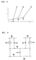
- the optical output, L, of a laser is a nonlinear function of the forward bias and modulation currents, or drive current, of the laser as shown in Figure 3.
- the threshold current varies among lasers, with laser aging, and as seen in Figure 3, also varies with temperature.
- Figure 3 illustrates graphically the threshold current variation with temperature of the laser being driven, as well as how the drive current is temperature dependent.
- the drive current is illustrated for three temperatures, a low temperature T L , medium temperature T M and high temperature T H , over the operating range of the laser.
- the threshold current for each of the low, medium, and high temperature ranges is shown as I L , I M , and I H , respectively.
- FIG. 4 A thermal model is shown in Figure 4 that may be used to analytically evaluate the temperature of the laser based on the temperature sensed by temperature sensor 38 on integrated circuit 18.
- Figure 4 represents a thermal model 400 of laser driver 10.
- Node 402 represents the temperature measured at the integrated circuit 18, temperature sensor 38.
- Node 404 represents the temperature at laser 14.
- Node 406 represents the temperature at the housing or case in which the laser and integrated circuit are packaged.
- Node 408 represents the ambient, an infinite reservoir for heat dissipation.
- Thermal resistance 410 represents the thermal resistance between heat generated in integrated circuit 18 and the housing or case in which the laser and integrated circuit are packaged.
- Current generator 412 represents the heat generated by the drive circuit, which is a function of the drive current provided to the laser.
- Thermal resistance 414 represents the thermal resistance between heat generated in the laser and the housing or case in which the laser and integrated circuit are packaged.
- Current generator 416 represents heat generated at laser 14, which is a function of the laser drive current.
- Thermal resistance 418 represents a thermal resistance between the case or housing and the surrounding ambient.
- model 400 By varying parameters in model 400, the thermal characteristics of laser driver 10 can be modeled to determine the appropriate laser drive current for measured temperatures at integrated circuit 18 under the modeled conditions. While a more complex thermal model could be employed, applicants have found this model to suffice. Model 400 is versatile and can accommodate many variations in locating the integrated circuit and laser relative to each other, various packaging materials and shapes, as well as environmental factors such as ambient air or forced air environment.
- model equations may be solved in any known manner by one skilled in the art. Solving the model equations may be recursive until a solution converges, as is known in the art.
- While the invention has been described as measuring the temperature of an integrated circuit that generates drive current for a laser and converting the temperature of the integrated circuit to a corresponding temperature at the laser and generating a drive current for the laser that is a function of the corresponding temperature at the laser, it should be readily recognized that once the relationship between the temperature of the integrated circuit and the corresponding temperature at the laser is determined, it is not necessary to generate the actual temperature at the laser. In this manner, it is contemplated that it is not necessary to generate the actual temperature at the laser but rather be able to generate a drive current for the laser that is a function of the temperature at the laser.
Landscapes
- Physics & Mathematics (AREA)
- Electromagnetism (AREA)
- Condensed Matter Physics & Semiconductors (AREA)
- General Physics & Mathematics (AREA)
- Optics & Photonics (AREA)
- Engineering & Computer Science (AREA)
- Signal Processing (AREA)
- Computer Networks & Wireless Communication (AREA)
- Semiconductor Lasers (AREA)
Abstract
There is disclosed a laser driver (10) or transmitter in which a drive current is generated by monitoring the temperature of an integrated circuit that generates drive current for the laser. The temperature sensed at the integrated circuit is transformed to a corresponding temperature at the laser. A drive current is generated for the laser that is dependent on the corresponding temperature at the laser.
Description
- This invention relates generally to laser drivers or transmitters, and particularly to laser drivers having temperature compensation.
- The optical output (light) of a laser diode or laser is a nonlinear function of the current driving the laser. The light-current characteristic of a laser is also temperature dependent. The minimum driving current that causes the laser to operate in a lasing mode is known as the threshold current. Over the temperature operating range of a laser, higher operating temperatures require higher threshold currents to cause the laser to operate in a lasing mode. Correspondingly, lower operating temperatures require smaller threshold currents to cause the laser to operate in a lasing mode. The threshold current is a function of the operating temperature of the laser and may vary as much as an order of magnitude over the temperature operating range of the laser.
- Integrated circuits are employed to modulate data onto the laser output. The laser is turned on and off by a driving current commensurate with the data to be modulated. The driving current is generally comprised of two components, a bias current that maintains the laser at the edge of operating in the lasing mode and a modulation current. The bias current has been controlled to be the threshold current of the laser. Since a laser will not operate in the lasing mode until the threshold current has been reached (or exceeded) it is important that the bias current be controlled precisely to be the threshold current at the temperature at which the laser is operating. Should the bias current fall below the threshold current, an unacceptable laser turn-on delay occurs. A turn-on delay is particularly undesirable when the laser operates at high switching speeds. A bias current higher than the threshold current is also undesirable because an extinction ratio problem is introduced into the laser output. An extinction ratio problem occurs when the light emitted by the laser should decrease to zero, and not be offset from zero, when the modulation current component of the laser drive circuit is zero, however the light emitted by the laser does not decrease to zero due to the bias current being higher than the threshold current. It is thus desirable to maintain the bias current precisely at the threshold current level for the temperature at which the laser is operating.
- In one known bias current control technique, such as disclosed in U. S. Patent 5,019,769, a laser and backface diode are mounted on a thermoelectric cooler. The thermoelectric cooler maintains the laser operating temperature at a controlled set point. A laser temperature sensor, also mounted on the thermoelectric cooler, senses the temperature of the thermoelectric cooler which is the same temperature as the operating temperature of the laser. A laser controller employs a programmed microcontroller to sense the laser temperature, control the thermoelectric cooler (and hence the laser temperature), and control the process of turning on and selecting the operating point of the laser. Using a thermoelectric coder introduces additional cost and requires more complex controls.
- In another known technique, a temperature compensating circuit is mounted in thermal contact with the laser. A temperature compensating circuit produces a current component for driving the laser that is proportional to the operating temperature of the laser. This technique varies the laser drive current to compensate for temperature variations, without the need for a thermoelectric cooler.
- In accordance with the present invention, a drive current for a laser driver is generated by monitoring the temperature of an integrated circuit that generates drive current for the laser. The temperature sensed at the integrated circuit is transformed to a corresponding temperature at the laser. A drive current is generated for the laser that is dependent on the corresponding temperature at the laser.
- The invention will be described by way of example in which:
- Figure 1 is a block diagram illustration of a laser package, including control electronics, in accordance with the present invention;
- Figure 2 is a schematic diagram of a portion of the control electronics in the block diagram of Figure 1;
- Figure 3 is a graphical illustration of the optical output of a laser, L, for a given drive current, i, at three temperatures over the operating temperature range of a laser; and
- Figure 4 is a electrical representation of a thermodynamic model of a laser transmitter package that may be used to analytically determine, from a temperature at the integrated circuit, a corresponding temperature at the laser over the operating temperature range of the laser.
- An illustrative embodiment of a
laser driver 10 in accordance with the present invention is shown in Figure 1.Laser driver 10 is enclosed in apackage 12 which is represented symbolically.Laser driver 10 includes a laser 14, abackface diode 16, an integratedcircuit 18 providing a multiplicity of functions, and a look-up table 20 such as an electrically erasable programmable read only memory (EEPROM). A remotely sensed temperature at integratedcircuit 18 is translated through data stored in look-up table 20 to a corresponding temperature at laser 14, and laser 14 is controlled in response to the corresponding temperature at the laser.Laser driver 10 may also include alens 22 for focusing light emitted by laser 14. - Laser 14 has a
front facet 24 from whichcoherent light 26 is emitted. The coherent light, which may be passed throughlens 22, is passed into afiber 28 for transmission. A small portion of the light emitted from laser 14 is emitted fromrear facet 30. Aportion 32 of the light emitted fromrear facet 30 impinges onbackface diode 16. Since the optical power output fromfront facet 24 of laser 14 is proportional to the optical power output fromrear facet 30,backface diode 16 continuously monitors the optical power output by laser 14. The optical power output by laser 14 can be correlated to heat generated by laser 14.Backface diode 16 provides a signal, such as a current, over aconductor 34 to thecontrol portion 36 ofintegrated circuit 18. - The temperature within
package 12 has local variations. There is not a single temperature withinpackage 12. Some components generate or dissipate more heat than other components, and some regions of the package may dissipate heat transferred to it from heat generating components more readily than other regions of the package. In accordance with the present invention, a temperature is measured on an integratedcircuit 18 withinpackage 12 oflaser driver 10, remotely relative to laser 14. Thus, the temperature of laser 14 is not measured. The measured temperature may be less than or greater than the temperature of laser 14. Typically, the measured temperature will be lower than the temperature of laser 14. The temperature is measured by atemperature sensor 38 on integratedcircuit 18, such as a temperature sensitive circuit, varying a temperature sensitive parameter. The temperature sensitive parameter either is or creates a temperature sensitive signal. In the illustrative embodiment, the temperature sensitive signal is converted from an analog form to a digital form in analog-to-digital converter 40 onintegrated circuit 18, which in turn is converted byaddress generator 42 to a corresponding address. The address so generated is used to access look-up table 20 to retrieve data stored at that address relative to operation oflaser driver 10 at a corresponding temperature. Also retrieved may be other data such as back face monitor setpoint, the value at which to limit current to the laser should it fail which is the extremum aging coefficient or current. The aging coefficient is ratio of the actual laser threshold 5 current, at a given temperature, to the beginning-of-life threshold current at the same temperature. This data may representmultiple channels 44 of data. The data stored in look-up table 20 is predetermined from a model described below with respect to Figure 4. The measured temperature is a temperature on integratedcircuit 18 that corresponds to an operating temperature of laser 14. The data predetermined and stored in look-up table 20 is based on the temperature at the laser corresponding to the measured temperature. - The data retrieved from look-up table 20 over
channels 44 is provided to control 36 and may include a digital representation of the backface diodecurrent set point 46, a digital representation of the desired bias andmodulation currents backface diode 16 is digitized by analog-to-digital converter 54 for comparison incomparator 56 to the digital representation of the backface diodecurrent set point 46 retrieved from look-up table 20. If the digital representation of the current signal is greater than the backface diode setpoint 46, a feedback loop operates in that up-down counter 58 counts down. This correction is used to multiply, inmultipliers rear facet 30. This feedback loop eliminates the difference betweenset point 46 and the digital representation of the backface diode output. The counter output, when multiplied with the digital representation of the bias current, results in a modified bias current 48' that is provided todriver 43, which in turn generates the drive current to drive laser 14. If the digital representation of the current signal frombackface diode 16 is less than the backface diode setpoint 46, the feedback loop operates in that up-down counter 58 counts up, as limited by maximum aging coefficient 52 inupper limit 68, increasing its output todriver 43, which increases the drive current to laser 14 and in turn increases the portion of light 32 emitted fromrear facet 30. Again, operation of the feedback loop eliminates the difference betweenset point 46 and the digital representation of the backface diode output. - If appropriate, modulation current 50 for the sensed temperature is also retrieved from look-up table 20. As shown in Figure 2, either or both of the bias current 48 and modulation current 50 can be modified, such as by multiplication factors M1 and M2 respectively, in
multipliers driver 43. The digital representations of bias current 48' and the digital representation of modulation current 50' are provideddriver 43 to be converted to an analog current signal to drive laser 14. Data to modulate the operation of laser 14 is also provided todriver 43. The data is used bydriver 43 to switch on and off the modulation current. - Upon power-up of
laser driver 10, with the feedback loop turned off, configuration information is downloaded from look-up table 20. This is done since the same integrated circuit and look-up table can be used for various configurations in the physical packaging oflaser driver 10. The predetermined digital representations of drive current stored in the look-up table are unique to the package and components in the package. The temperature is sensed bytemperature sensor 38 and once the temperature is sensed and the various analog-to-digital and digital-to-analog converters settle, the feedback loop is turned on to control operation oflaser driver 10. - The optical output, L, of a laser is a nonlinear function of the forward bias and modulation currents, or drive current, of the laser as shown in Figure 3. When drive current is applied to a laser, the laser does not commence lasing operation until the drive current reaches a minimum, known as the threshold current. The threshold current varies among lasers, with laser aging, and as seen in Figure 3, also varies with temperature. Figure 3 illustrates graphically the threshold current variation with temperature of the laser being driven, as well as how the drive current is temperature dependent. The drive current is illustrated for three temperatures, a low temperature TL, medium temperature TM and high temperature TH, over the operating range of the laser. The threshold current for each of the low, medium, and high temperature ranges is shown as IL, IM, and IH, respectively.
- A thermal model is shown in Figure 4 that may be used to analytically evaluate the temperature of the laser based on the temperature sensed by
temperature sensor 38 on integratedcircuit 18. Figure 4 represents athermal model 400 oflaser driver 10.Node 402 represents the temperature measured at theintegrated circuit 18,temperature sensor 38.Node 404 represents the temperature at laser 14.Node 406 represents the temperature at the housing or case in which the laser and integrated circuit are packaged.Node 408 represents the ambient, an infinite reservoir for heat dissipation.Thermal resistance 410 represents the thermal resistance between heat generated inintegrated circuit 18 and the housing or case in which the laser and integrated circuit are packaged.Current generator 412 represents the heat generated by the drive circuit, which is a function of the drive current provided to the laser.Thermal resistance 414 represents the thermal resistance between heat generated in the laser and the housing or case in which the laser and integrated circuit are packaged.Current generator 416 represents heat generated at laser 14, which is a function of the laser drive current.Thermal resistance 418 represents a thermal resistance between the case or housing and the surrounding ambient. - By varying parameters in
model 400, the thermal characteristics oflaser driver 10 can be modeled to determine the appropriate laser drive current for measured temperatures atintegrated circuit 18 under the modeled conditions. While a more complex thermal model could be employed, applicants have found this model to suffice.Model 400 is versatile and can accommodate many variations in locating the integrated circuit and laser relative to each other, various packaging materials and shapes, as well as environmental factors such as ambient air or forced air environment. - The model equations may be solved in any known manner by one skilled in the art. Solving the model equations may be recursive until a solution converges, as is known in the art.
- While the invention has been described as measuring the temperature of an integrated circuit that generates drive current for a laser and converting the temperature of the integrated circuit to a corresponding temperature at the laser and generating a drive current for the laser that is a function of the corresponding temperature at the laser, it should be readily recognized that once the relationship between the temperature of the integrated circuit and the corresponding temperature at the laser is determined, it is not necessary to generate the actual temperature at the laser. In this manner, it is contemplated that it is not necessary to generate the actual temperature at the laser but rather be able to generate a drive current for the laser that is a function of the temperature at the laser.
- While the invention has been described as predetermining a plurality of discrete drive currents over a range of corresponding laser temperatures, which suggests a digital implementation, it is recognized that the invention could be implemented in a total analog capability.
- While the invention has been described as predetermining digital representations of the bias and modulation current data for the look-up table using a thermal model, alternatively the digital representations of the bias and modulation current data could be determined by empirical testing.
- While the maximum aging current has been disclosed as limiting the output of an up-down counter when counting up, the invention is not limited thereto. Other techniques of implementing the aging coefficient are contemplated within the scope of the invention.
Claims (8)
- A method of generating a drive current for a laser, characterized by the steps of:monitoring the temperature of an integrated circuit that generates drive current for a laser;converting the temperature of the integrated circuit to a corresponding temperature at the laser; andgenerating a drive current for the laser that is a function of the corresponding temperature at the laser.
- The method as recited in claim 1, wherein the converting step characterized by entering a look-up table with a representation of the integrated circuit temperature to obtain the corresponding temperature at the laser.
- The method as recited in claim 1 or 2, wherein the generating step is characterized bypredetermining a plurality of discrete drive currents over a range of corresponding laser temperatures; andstoring a digital representation of the plurality of discrete drive currents in a look-up table.
- The method as recited in claim 1, 2 or 3, further characterized by the steps of:entering the look-up table based on a temperature of the integrated circuit; andretrieving from the look-up table a digital representation of one of the plurality of drive currents that correlates to the temperature of the integrated circuit.
- A laser transmitter, characterized bya laser (14) for receiving a drive current and for emitting light in response thereto;an integrated circuit (18) for generating the drive current for the laser (14), the integrated circuit comprising a temperature sensing circuit (38) that senses the temperature of the integrated circuit, the integrated circuit converting the temperature at the integrated circuit to a representation corresponding to the temperature at the laser;a look-up table (20) for receiving the representation corresponding to the temperature at the laser (14) and for generating a representation of a corresponding drive current; anda driver for converting the representation of the drive current into a drive current, the drive current provided to the laser.
- The laser transmitter (14) as recited in claim 5, characterized in that the look-up table (20) is stored in an electrically erasable programmable read only memory.
- The laser transmitter (14) as recited in claim 5 or 6, characterized in that the representation of the corresponding drive current is a digital representation.
- The laser transmitter (14) as recited in claim 5, 6 or 7, characterized in that the driver is a digital-to-analog converter.
Applications Claiming Priority (2)
| Application Number | Priority Date | Filing Date | Title |
|---|---|---|---|
| US1237896P | 1996-02-27 | 1996-02-27 | |
| US12378 | 1996-02-27 |
Publications (1)
| Publication Number | Publication Date |
|---|---|
| EP0793316A1 true EP0793316A1 (en) | 1997-09-03 |
Family
ID=21754682
Family Applications (1)
| Application Number | Title | Priority Date | Filing Date |
|---|---|---|---|
| EP97301248A Ceased EP0793316A1 (en) | 1996-02-27 | 1997-02-25 | Laser driver with temperature sensor on an integrated circuit |
Country Status (4)
| Country | Link |
|---|---|
| US (1) | US5844928A (en) |
| EP (1) | EP0793316A1 (en) |
| JP (1) | JPH09321375A (en) |
| KR (1) | KR970063849A (en) |
Cited By (13)
| Publication number | Priority date | Publication date | Assignee | Title |
|---|---|---|---|---|
| EP1069658A1 (en) * | 1999-07-13 | 2001-01-17 | Lucent Technologies Inc. | Method and apparatus for active numeric temperature compensation of an etalon in a wavelength stabilized laser |
| EP1085624A1 (en) * | 1999-09-17 | 2001-03-21 | Thomson-Csf | Method and device for optical power stabilisation of a laser emitter |
| EP1233488A1 (en) * | 2001-02-16 | 2002-08-21 | Agilent Technologies, Inc. (a Delaware corporation) | A light source |
| WO2002069464A1 (en) * | 2001-02-23 | 2002-09-06 | Fujitsu Limited | Light transmitter |
| EP1283569A2 (en) * | 2001-06-13 | 2003-02-12 | Motorola, Inc. | Laser diode control apparatus |
| EP1345296A1 (en) * | 2002-03-16 | 2003-09-17 | Agilent Technologies, Inc. (a Delaware corporation) | System for controlling power, wavelength and extinction ratio in optical sources, and computer program product therefor |
| GB2406210A (en) * | 2003-09-16 | 2005-03-23 | Agilent Technologies Inc | control apparatus and method for an electromagnetic radiation device |
| US6947457B2 (en) | 2000-02-14 | 2005-09-20 | Yokogawa Electric Corporation | DFB laser driving device, DFB laser driving method and storage medium |
| EP1594238A2 (en) * | 2004-05-06 | 2005-11-09 | Avanex Corporation | Method and system for controlling laser diodes in optical communications systems |
| EP1603205A1 (en) * | 2004-06-04 | 2005-12-07 | Agilent Technologies | System and method for controlling optical sources, such as laser diodes, and computer program product therefor |
| US6982689B2 (en) | 2002-05-24 | 2006-01-03 | Freescale Semiconductor, Inc | Light-emitting element drive apparatus |
| US8588622B2 (en) | 2009-03-30 | 2013-11-19 | Fujitsu Optical Components Limited | Optical light source control with auxiliary controller |
| WO2020033050A1 (en) * | 2018-08-10 | 2020-02-13 | Microsoft Technology Licensing, Llc | Laser control |
Families Citing this family (76)
| Publication number | Priority date | Publication date | Assignee | Title |
|---|---|---|---|---|
| US6446867B1 (en) | 1995-11-22 | 2002-09-10 | Jorge Sanchez | Electro-optic interface system and method of operation |
| JP3218999B2 (en) * | 1996-12-18 | 2001-10-15 | 安藤電気株式会社 | External cavity type tunable semiconductor laser light source |
| US6494370B1 (en) | 1997-12-11 | 2002-12-17 | Ceyx Technologies | Electro-optic system controller and method of operation |
| US6317235B1 (en) * | 1998-08-28 | 2001-11-13 | Zilog, Inc. | Method and system for preventing burn-out of infrared transmitter diodes |
| US6624917B1 (en) * | 1999-10-28 | 2003-09-23 | International Business Machines Corporation | Optical power adjustment circuits for parallel optical transmitters |
| US20060153256A1 (en) * | 1999-12-24 | 2006-07-13 | Jorge Sanchez | Laser temperature performance compensation |
| DE20007884U1 (en) * | 2000-05-02 | 2001-09-06 | Ic Haus Gmbh | Monolithically integrated circuit for regulating the light output of a laser diode |
| JP2002197709A (en) * | 2000-10-18 | 2002-07-12 | Sony Corp | Recording and reproducing device, state detecting method and data output method, information processor and information processing method, and recording medium |
| US6947456B2 (en) * | 2000-12-12 | 2005-09-20 | Agilent Technologies, Inc. | Open-loop laser driver having an integrated digital controller |
| US7079775B2 (en) | 2001-02-05 | 2006-07-18 | Finisar Corporation | Integrated memory mapped controller circuit for fiber optics transceiver |
| GB2377838A (en) * | 2001-07-21 | 2003-01-22 | Zarlink Semiconductor Ab | Programmable EPROM controller for optical transmitter array |
| US6917639B2 (en) * | 2001-08-09 | 2005-07-12 | Ricoh Company, Ltd. | Laser driver circuit |
| EP1470522A4 (en) * | 2001-12-27 | 2005-10-05 | Ceyx Technologies Inc | Laser optics integrated control system and method of operation |
| US6628373B2 (en) | 2002-01-09 | 2003-09-30 | Trimble Navigation Limited | Laser transmitter with thermally induced error compensation and method of transmitter compensation |
| US6621560B2 (en) * | 2002-01-09 | 2003-09-16 | Trimble Navigation Limited | Laser transmitter with thermally induced error compensation and method of transmitter compensation |
| AU2003226442A1 (en) * | 2002-01-14 | 2003-09-02 | Ceyx Technologies, Inc. | Laser temperature performance compensation |
| EP1329997A1 (en) * | 2002-01-16 | 2003-07-23 | Lucent Technologies Inc. | Laser light transmitter and laser light transceiver with laser diode with feed forward control |
| DE10240083A1 (en) * | 2002-08-30 | 2004-03-11 | Austriamicrosystems Ag | Method of calibrating a photodiode, semiconductor chip and operating method |
| JP2004111827A (en) * | 2002-09-20 | 2004-04-08 | Alps Electric Co Ltd | Optical output control circuit of semiconductor laser |
| CA2475850A1 (en) * | 2003-01-08 | 2003-07-29 | Ceyx Technologies, Inc. | Apparatus and method for measurement of dynamic laser signals |
| US6891866B2 (en) * | 2003-01-10 | 2005-05-10 | Agilent Technologies, Inc. | Calibration of laser systems |
| US6943505B2 (en) * | 2003-06-05 | 2005-09-13 | Infineon Technologies Ag | Driving device for a light-emitting component and a method for driving a light-emitting component |
| US8068739B2 (en) * | 2003-06-12 | 2011-11-29 | Finisar Corporation | Modular optical device that interfaces with an external controller |
| US7646028B2 (en) * | 2003-06-17 | 2010-01-12 | Semiconductor Components Industries, L.L.C. | LED driver with integrated bias and dimming control storage |
| US20050060114A1 (en) * | 2003-08-29 | 2005-03-17 | Finisar | Testing and storing tuning information in modular optical devices |
| US9065571B2 (en) * | 2003-08-29 | 2015-06-23 | Finisar Corporation | Modular controller that interfaces with modular optical device |
| US8923704B2 (en) * | 2003-08-29 | 2014-12-30 | Finisar Corporation | Computer system with modular optical devices |
| US8891970B2 (en) * | 2003-08-29 | 2014-11-18 | Finisar Corporation | Modular optical device with mixed signal interface |
| US7321606B2 (en) * | 2003-10-09 | 2008-01-22 | National Semiconductor Corporation | Laser trim and compensation methodology for passively aligning optical transmitter |
| US7702030B2 (en) * | 2003-12-17 | 2010-04-20 | Mindspeed Technologies, Inc. | Module to module signaling with jitter modulation |
| JP2005203536A (en) * | 2004-01-15 | 2005-07-28 | Matsushita Electric Ind Co Ltd | Optical transmitter |
| US7369587B2 (en) * | 2004-02-21 | 2008-05-06 | Finisar Corp | Temperature control for coarse wavelength division multiplexing systems |
| US7346086B2 (en) * | 2004-04-02 | 2008-03-18 | Videojet Technologies, Inc. | Apparatus for monitoring the operating status of a laser |
| JP2005340931A (en) * | 2004-05-24 | 2005-12-08 | Freescale Semiconductor Inc | Burst signal receiver |
| US20050271100A1 (en) * | 2004-06-04 | 2005-12-08 | Keith Everett | System and method for controlling optical sources, such as laser diodes, and computer program product therefor |
| US7102121B2 (en) * | 2004-06-29 | 2006-09-05 | Magiq Technologies, Inc. | Temperature compensation for QKD systems |
| US7551852B2 (en) * | 2004-08-10 | 2009-06-23 | Mindspeed Technologies, Inc. | Module to module signaling |
| US7583902B2 (en) * | 2004-08-10 | 2009-09-01 | Mindspeed Technologies, Inc. | Module to module signaling utilizing amplitude modulation |
| US7270490B2 (en) * | 2004-08-31 | 2007-09-18 | Finisar Corporation | Laser package with digital electronic interface |
| US7504610B2 (en) * | 2004-09-03 | 2009-03-17 | Mindspeed Technologies, Inc. | Optical modulation amplitude compensation system having a laser driver with modulation control signals |
| US7608806B2 (en) * | 2004-11-19 | 2009-10-27 | Mindspeed Technologies, Inc. | Multiple parameter laser power control with automatic compensation |
| KR100725687B1 (en) * | 2004-11-30 | 2007-06-07 | 삼성전자주식회사 | Method and apparatus for compensation temperature characteristics of laser diode in an optical communication system |
| JP4670364B2 (en) * | 2005-01-21 | 2011-04-13 | 富士ゼロックス株式会社 | Optical communication device |
| US7400662B2 (en) * | 2005-01-26 | 2008-07-15 | Avago Technologies Fiber Ip Pte Ltd | Calibration of laser systems |
| JP2007180378A (en) * | 2005-12-28 | 2007-07-12 | Sumitomo Electric Ind Ltd | Laser module and control method therefor |
| US7853154B2 (en) * | 2006-01-13 | 2010-12-14 | Mindspeed Technologies, Inc. | Bias circuit for burst-mode/TDM systems with power save feature |
| US8611384B2 (en) * | 2006-05-18 | 2013-12-17 | Finisar Corporation | High-temperature operation of vertical cavity surface emitting lasers |
| US7822086B2 (en) * | 2007-07-27 | 2010-10-26 | Microvision, Inc. | Laser projection temperature compensation |
| WO2009055035A2 (en) * | 2007-10-26 | 2009-04-30 | Mindspeed Technologies, Inc. | High sensitivity two-stage amplifier |
| US7711018B2 (en) * | 2007-12-21 | 2010-05-04 | Microvision, Inc. | Method and apparatus for laser diode compensation |
| US8750341B2 (en) * | 2008-01-04 | 2014-06-10 | Mindspeed Technologies, Inc. | Method and apparatus for reducing optical signal speckle |
| WO2009145819A2 (en) | 2008-03-31 | 2009-12-03 | Mindspeed Technologies, Inc. | Reducing power dissipation in portable lcos/lcd/dlp projection systems |
| US8159956B2 (en) | 2008-07-01 | 2012-04-17 | Finisar Corporation | Diagnostics for serial communication busses |
| JP2010157662A (en) * | 2009-01-05 | 2010-07-15 | Sumitomo Electric Ind Ltd | Laser diode driving circuit and laser diode driving method |
| US8665920B2 (en) * | 2010-01-27 | 2014-03-04 | Microvision, Inc. | Method and apparatus for laser diode compensation |
| JP2012074793A (en) * | 2010-09-28 | 2012-04-12 | Yazaki Corp | Signal transmission device |
| US8643296B2 (en) | 2010-11-22 | 2014-02-04 | Mindspeed Technologies, Inc. | Color mixing and desaturation with reduced number of converters |
| JP2012142417A (en) * | 2010-12-28 | 2012-07-26 | Sumitomo Electric Device Innovations Inc | Control method of laser diode |
| US9107245B2 (en) | 2011-06-09 | 2015-08-11 | Mindspeed Technologies, Inc. | High accuracy, high dynamic range LED/laser driver |
| US8934779B2 (en) * | 2012-02-10 | 2015-01-13 | Source Photonics, Inc. | Operational status indicators in an optical transceiver using dynamic thresholds |
| US9385606B2 (en) | 2012-12-03 | 2016-07-05 | M/A-Com Technology Solutions Holdings, Inc. | Automatic buck/boost mode selection system for DC-DC converter |
| US10097908B2 (en) | 2014-12-31 | 2018-10-09 | Macom Technology Solutions Holdings, Inc. | DC-coupled laser driver with AC-coupled termination element |
| US10044328B2 (en) | 2015-07-20 | 2018-08-07 | Macom Technology Solutions Holdings, Inc. | Transimpedance amplifier with bandwidth extender |
| JP6717082B2 (en) * | 2016-06-30 | 2020-07-01 | 富士通オプティカルコンポーネンツ株式会社 | Optical transmission module and method of controlling optical transmission module |
| WO2018045093A1 (en) | 2016-08-30 | 2018-03-08 | Macom Technology Solutions Holdings, Inc. | Driver with distributed architecture |
| WO2018082019A1 (en) * | 2016-11-04 | 2018-05-11 | 深圳盈达信息科技有限公司 | Temperature measurement scanning head and using method therefor |
| US9985414B1 (en) | 2017-06-16 | 2018-05-29 | Banner Engineering Corp. | Open-loop laser power-regulation |
| US10630052B2 (en) | 2017-10-04 | 2020-04-21 | Macom Technology Solutions Holdings, Inc. | Efficiency improved driver for laser diode in optical communication |
| JP6998789B2 (en) * | 2018-02-14 | 2022-01-18 | 古河電気工業株式会社 | Wavelength variable laser device and wavelength control method for tunable laser device |
| US11005573B2 (en) | 2018-11-20 | 2021-05-11 | Macom Technology Solutions Holdings, Inc. | Optic signal receiver with dynamic control |
| CN110289550B (en) * | 2019-06-25 | 2020-08-18 | 深圳市亚派光电器件有限公司 | Current correction method and device for optical module and computer readable storage medium |
| WO2021142216A1 (en) | 2020-01-10 | 2021-07-15 | Macom Technology Solutions Holdings, Inc. | Optimal equalization partitioning |
| US11575437B2 (en) | 2020-01-10 | 2023-02-07 | Macom Technology Solutions Holdings, Inc. | Optimal equalization partitioning |
| US11609116B2 (en) | 2020-08-27 | 2023-03-21 | Banner Engineering Corp | Open-loop photodiode gain regulation |
| US11658630B2 (en) | 2020-12-04 | 2023-05-23 | Macom Technology Solutions Holdings, Inc. | Single servo loop controlling an automatic gain control and current sourcing mechanism |
| US11616529B2 (en) | 2021-02-12 | 2023-03-28 | Macom Technology Solutions Holdings, Inc. | Adaptive cable equalizer |
Citations (5)
| Publication number | Priority date | Publication date | Assignee | Title |
|---|---|---|---|---|
| JPS60251731A (en) * | 1984-05-29 | 1985-12-12 | Fujitsu Ltd | Optical output controller |
| US4710631A (en) * | 1984-08-28 | 1987-12-01 | Fuji Photo Film Co., Ltd. | Temperature compensation for a semiconductor light source used for exposure of light sensitive material |
| JPH0220084A (en) * | 1988-07-08 | 1990-01-23 | Nec Corp | Circuit for stabilizing oscillating wavelength of laser diode |
| EP0421674A2 (en) * | 1989-10-06 | 1991-04-10 | AT&T Corp. | Laser driver with temperature compensation |
| EP0431832A2 (en) * | 1989-12-04 | 1991-06-12 | AT&T GLOBAL INFORMATION SOLUTIONS INTERNATIONAL INC. | Apparatus and method for controlling the operation of a semiconductor device |
Family Cites Families (5)
| Publication number | Priority date | Publication date | Assignee | Title |
|---|---|---|---|---|
| US5019769A (en) * | 1990-09-14 | 1991-05-28 | Finisar Corporation | Semiconductor laser diode controller and laser diode biasing control method |
| JP2546080B2 (en) * | 1991-05-10 | 1996-10-23 | 富士通株式会社 | Semiconductor laser control device |
| US5337254A (en) * | 1991-12-16 | 1994-08-09 | Hewlett-Packard Company | Programmable integrated circuit output pad |
| US5278404A (en) * | 1992-07-20 | 1994-01-11 | At&T Bell Laboratories | Optical sub-system utilizing an embedded micro-controller |
| JP4046778B2 (en) * | 1995-04-05 | 2008-02-13 | ソニー株式会社 | Optical disk recording / reproducing device |
-
1997
- 1997-02-20 US US08/803,405 patent/US5844928A/en not_active Expired - Lifetime
- 1997-02-25 EP EP97301248A patent/EP0793316A1/en not_active Ceased
- 1997-02-27 KR KR1019970006158A patent/KR970063849A/en not_active Application Discontinuation
- 1997-02-27 JP JP9043121A patent/JPH09321375A/en active Pending
Patent Citations (5)
| Publication number | Priority date | Publication date | Assignee | Title |
|---|---|---|---|---|
| JPS60251731A (en) * | 1984-05-29 | 1985-12-12 | Fujitsu Ltd | Optical output controller |
| US4710631A (en) * | 1984-08-28 | 1987-12-01 | Fuji Photo Film Co., Ltd. | Temperature compensation for a semiconductor light source used for exposure of light sensitive material |
| JPH0220084A (en) * | 1988-07-08 | 1990-01-23 | Nec Corp | Circuit for stabilizing oscillating wavelength of laser diode |
| EP0421674A2 (en) * | 1989-10-06 | 1991-04-10 | AT&T Corp. | Laser driver with temperature compensation |
| EP0431832A2 (en) * | 1989-12-04 | 1991-06-12 | AT&T GLOBAL INFORMATION SOLUTIONS INTERNATIONAL INC. | Apparatus and method for controlling the operation of a semiconductor device |
Non-Patent Citations (2)
| Title |
|---|
| PATENT ABSTRACTS OF JAPAN vol. 010, no. 117 (E - 400) 2 May 1986 (1986-05-02) * |
| PATENT ABSTRACTS OF JAPAN vol. 014, no. 163 (E - 0910) 29 March 1990 (1990-03-29) * |
Cited By (21)
| Publication number | Priority date | Publication date | Assignee | Title |
|---|---|---|---|---|
| US6516010B1 (en) | 1999-07-13 | 2003-02-04 | Agere Systems, Inc. | Method and apparatus for active numeric temperature compensation of an etalon in a wavelength stabilized laser |
| EP1069658A1 (en) * | 1999-07-13 | 2001-01-17 | Lucent Technologies Inc. | Method and apparatus for active numeric temperature compensation of an etalon in a wavelength stabilized laser |
| US6928092B2 (en) | 1999-07-13 | 2005-08-09 | Agere Systems Inc. | Method and apparatus for active numeric temperature compensation of an etalon in a wavelength stabilized laser |
| EP1085624A1 (en) * | 1999-09-17 | 2001-03-21 | Thomson-Csf | Method and device for optical power stabilisation of a laser emitter |
| FR2798780A1 (en) * | 1999-09-17 | 2001-03-23 | Thomson Csf | METHOD AND DEVICE FOR MONITORING THE OPTICAL POWER OF A LASER TRANSMITTER |
| US6947457B2 (en) | 2000-02-14 | 2005-09-20 | Yokogawa Electric Corporation | DFB laser driving device, DFB laser driving method and storage medium |
| EP1233488A1 (en) * | 2001-02-16 | 2002-08-21 | Agilent Technologies, Inc. (a Delaware corporation) | A light source |
| WO2002069464A1 (en) * | 2001-02-23 | 2002-09-06 | Fujitsu Limited | Light transmitter |
| US6748181B2 (en) | 2001-02-23 | 2004-06-08 | Fujitsu Limited | Optical transmitter provided with optical output control function |
| EP1283569A2 (en) * | 2001-06-13 | 2003-02-12 | Motorola, Inc. | Laser diode control apparatus |
| EP1283569A3 (en) * | 2001-06-13 | 2004-05-26 | Motorola, Inc. | Laser diode control apparatus |
| EP1345296A1 (en) * | 2002-03-16 | 2003-09-17 | Agilent Technologies, Inc. (a Delaware corporation) | System for controlling power, wavelength and extinction ratio in optical sources, and computer program product therefor |
| US6982689B2 (en) | 2002-05-24 | 2006-01-03 | Freescale Semiconductor, Inc | Light-emitting element drive apparatus |
| GB2406210A (en) * | 2003-09-16 | 2005-03-23 | Agilent Technologies Inc | control apparatus and method for an electromagnetic radiation device |
| EP1594238A2 (en) * | 2004-05-06 | 2005-11-09 | Avanex Corporation | Method and system for controlling laser diodes in optical communications systems |
| EP1594238A3 (en) * | 2004-05-06 | 2006-05-03 | Avanex Corporation | Method and system for controlling laser diodes in optical communications systems |
| EP1603205A1 (en) * | 2004-06-04 | 2005-12-07 | Agilent Technologies | System and method for controlling optical sources, such as laser diodes, and computer program product therefor |
| US8588622B2 (en) | 2009-03-30 | 2013-11-19 | Fujitsu Optical Components Limited | Optical light source control with auxiliary controller |
| WO2020033050A1 (en) * | 2018-08-10 | 2020-02-13 | Microsoft Technology Licensing, Llc | Laser control |
| US10651626B2 (en) | 2018-08-10 | 2020-05-12 | Microsoft Technology Licensing, Llc | Laser control |
| CN112567577A (en) * | 2018-08-10 | 2021-03-26 | 微软技术许可有限责任公司 | Laser control |
Also Published As
| Publication number | Publication date |
|---|---|
| US5844928A (en) | 1998-12-01 |
| KR970063849A (en) | 1997-09-12 |
| JPH09321375A (en) | 1997-12-12 |
Similar Documents
| Publication | Publication Date | Title |
|---|---|---|
| US5844928A (en) | Laser driver with temperature sensor on an integrated circuit | |
| EP0497431B1 (en) | An apparatus for driving a semiconductor laser device | |
| EP0431832B1 (en) | Apparatus and method for controlling the operation of a semiconductor device | |
| EP0762568B1 (en) | Process for maintaining a desired temperature of a laser | |
| US5018154A (en) | Semiconductor laser drive device | |
| US5579328A (en) | Digital control of laser diode power levels | |
| US7693196B2 (en) | Semiconductor laser driving unit and image forming apparatus having the same | |
| US20060153259A1 (en) | Laser drive, optical disc apparatus, and laser-driving method | |
| US20060159141A1 (en) | Optical transmitting module operable in wide temperature range | |
| EP0724784A4 (en) | Method and apparatus for stabilizing laser diode energy output | |
| EP0910143B1 (en) | Laser diode protecting circuit | |
| US8345721B2 (en) | Method for driving optical transmitter | |
| US20020114363A1 (en) | Light source | |
| US5987044A (en) | Semiconductor light source system having an optimized setting for driving a laser diode | |
| JP2006013252A (en) | Method and circuit for controlling laser diode, and optical transmitter | |
| US5313482A (en) | Method and circuit arrangement for correcting the light power output of a laser diode | |
| US20060072867A1 (en) | Optical transmitter | |
| EP0573670A1 (en) | Semiconductor optical source capable of compensating for temperature-induced variation of laser oscillation threshold. | |
| JP2929992B2 (en) | Optical transmission circuit | |
| US7065114B2 (en) | Apparatus and method for controlling optical disc write power | |
| KR102574422B1 (en) | Controller of optical transmitter | |
| JP2830794B2 (en) | Optical transmission circuit | |
| JP3743399B2 (en) | Laser diode control device and control method | |
| JP2004349532A (en) | Optical transmitter | |
| JP3810393B2 (en) | Laser diode driving apparatus and laser diode driving method |
Legal Events
| Date | Code | Title | Description |
|---|---|---|---|
| PUAI | Public reference made under article 153(3) epc to a published international application that has entered the european phase |
Free format text: ORIGINAL CODE: 0009012 |
|
| AK | Designated contracting states |
Kind code of ref document: A1 Designated state(s): DE FR GB |
|
| 17P | Request for examination filed |
Effective date: 19980211 |
|
| 17Q | First examination report despatched |
Effective date: 19990322 |
|
| RAP1 | Party data changed (applicant data changed or rights of an application transferred) |
Owner name: AGERE SYSTEMS OPTOELECTRONICS GUARDIAN CORPORATION |
|
| STAA | Information on the status of an ep patent application or granted ep patent |
Free format text: STATUS: THE APPLICATION HAS BEEN REFUSED |
|
| 18R | Application refused |
Effective date: 20020131 |