EP0793975A2 - Device for controlling a pacemaker based on the blood oxygen saturation - Google Patents
Device for controlling a pacemaker based on the blood oxygen saturation Download PDFInfo
- Publication number
- EP0793975A2 EP0793975A2 EP97250053A EP97250053A EP0793975A2 EP 0793975 A2 EP0793975 A2 EP 0793975A2 EP 97250053 A EP97250053 A EP 97250053A EP 97250053 A EP97250053 A EP 97250053A EP 0793975 A2 EP0793975 A2 EP 0793975A2
- Authority
- EP
- European Patent Office
- Prior art keywords
- arrangement according
- output
- operating parameter
- control
- evaluation
- Prior art date
- Legal status (The legal status is an assumption and is not a legal conclusion. Google has not performed a legal analysis and makes no representation as to the accuracy of the status listed.)
- Granted
Links
Images


Classifications
-
- A—HUMAN NECESSITIES
- A61—MEDICAL OR VETERINARY SCIENCE; HYGIENE
- A61N—ELECTROTHERAPY; MAGNETOTHERAPY; RADIATION THERAPY; ULTRASOUND THERAPY
- A61N1/00—Electrotherapy; Circuits therefor
- A61N1/18—Applying electric currents by contact electrodes
- A61N1/32—Applying electric currents by contact electrodes alternating or intermittent currents
- A61N1/36—Applying electric currents by contact electrodes alternating or intermittent currents for stimulation
- A61N1/362—Heart stimulators
- A61N1/365—Heart stimulators controlled by a physiological parameter, e.g. heart potential
- A61N1/36514—Heart stimulators controlled by a physiological parameter, e.g. heart potential controlled by a physiological quantity other than heart potential, e.g. blood pressure
- A61N1/36557—Heart stimulators controlled by a physiological parameter, e.g. heart potential controlled by a physiological quantity other than heart potential, e.g. blood pressure controlled by chemical substances in blood
Definitions
- the invention relates to an arrangement of the type specified in the preamble of claim 1.
- the EKG reflects the condition of the patient's metabolic or hemodynamic system only to a very limited extent and indirectly, so that an adjustment made in this way is often not really optimal.
- the adjustment process is also time-consuming for the doctor and harbors sources of error.
- a device for determining blood oxygen saturation which is specially designed for intracardiac use and whose measured values are to be used for frequency control of a pacemaker, is described in DE 31 52 963 C1.
- This device comprises a measuring probe with a red-emitting light-emitting diode (LED) and a photo transistor as well as a control and signal converter circuit in which the received (red) light intensity proportional photo current is converted with the aid of a reference signal into an electrical signal representing the red transmission of the blood.
- LED red-emitting light-emitting diode
- This is an expression of the blood oxygen saturation and thus the hemodynamic state of the patient and can be used for pacemaker control.
- the reference signal is obtained here in a second measurement with reverse voltage polarity, in which the specific measurement signal component is eliminated by a diode provided for this purpose in the measuring circuit.
- the comparison of the measurement and reference signal then provides the specific signal component.
- the measuring method according to DE 31 52 983 has the decisive disadvantage that the transmission or reflection measurement at a single measuring wavelength is only a relative measurement, with which changes in the blood oxygen concentration but not its absolute value can be determined.
- the control of a pacemaker with the values obtained in this method can therefore only be a trend control; an adjustment of output values or a calibration of the operating parameters had to be carried out on the basis of other variables.
- FIG. 2 is a graphical representation of the relative absorbance at 660 nm and at 950 nm as a function of the blood oxygen saturation SaO 2 .
- FIG. 3 is a representation equivalent to the information content in principle to FIG. 3, in which the quotient of infrared (IR) and red (R) absorption is plotted against SaO 2 at the wavelengths mentioned.
- the crosses denote values of the quotient in 10% steps, and these were connected by straight lines in the figure; the actual function curve is a hyperbola.
- the measuring arrangement comprises a photodetector, which is used equally for the detection of the transmission in the red and in the infrared spectral range.
- a photodetector which is used equally for the detection of the transmission in the red and in the infrared spectral range.
- US Pat. No. 4,712,179 discloses a method and a device for correcting the measurement values obtained via intracardiac measurement arrangements in cooperation with an implanted pacemaker with the aid of an external programming and evaluation device. This frees intracardially recorded measurement values from falsifications which result from inaccurate dimensioning of thick-film resistors in the manufacture of the pacemaker circuits, by determining sample-specific correction values for each pacemaker produced, stored in a ROM memory in the pacemaker when the measurement values are transferred to the The programming and evaluation device is also transmitted and used to calculate corrected measured values.
- the invention has for its object to provide an arrangement of the type mentioned with which an adjustment or calibration of a heart stimulator based on Measured values obtained via an external measuring device that reliably reflect the metabolic state of the patient are possible and can be designed in a structurally simple and variable manner and can be used in a variety of ways.
- the invention includes the idea of specifying or calibrating and calibrating operating parameters of a cardiac stimulator - cardiac pacemaker or defibrillator or cardioverter - based on absolute values obtained externally with sufficient accuracy, in the course of a programming process, of a non-electrical variable representative of the patient's metabolic state to specify a suitable automatic system.
- These parameters can in particular be the stimulation rate and / or the AV delay time.
- the invention further includes the provision of a measuring device in which a first measuring channel is formed with a component emitting visible light and a component receiving the visible light, and a second measuring channel is formed with a component emitting infrared radiation and a component receiving it. It also includes the idea of designing the control and evaluation device of the measuring device in such a way that both measurement channels can be operated simultaneously and the measurement signals obtained therein can be processed essentially simultaneously. This means that switchovers and intermediate signal storage can be dispensed with, which eliminates sources of error and ensures fast and trouble-free operation.
- the control and evaluation device of the measuring device can thus be designed such that the measurement signals can be processed promptly (on-line). This enables the rapid recording of measurement curves for changing the blood oxygen saturation - or another representative measurement variable - in response to the variation in operating parameters of the heart stimulator and thus a rapid optimization of the corresponding parameters on the basis of the measurement values.
- the accuracy of the measured values - in the case of the measured variable blood oxygen saturation - is further increased in that the emitting and / or the receiving components are designed and / or provided with filter means in such a way that the spectrum of the received light and that of the received infrared radiation essentially have no overlap area.
- the invention further includes the idea of connecting an input of the programming device to the output of a control and evaluation device for the non-electrical variable - such as blood oxygen saturation - and the programming device with means for automatically carrying out and evaluating a series of measurements for the non- electrical variable as a function of various values of the operating parameter set on the heart stimulator via the telemetry device and definition of an optimized operating parameter in accordance with the evaluation result of the series of measurements.
- a control and evaluation device for the non-electrical variable - such as blood oxygen saturation -
- the programming device with means for automatically carrying out and evaluating a series of measurements for the non- electrical variable as a function of various values of the operating parameter set on the heart stimulator via the telemetry device and definition of an optimized operating parameter in accordance with the evaluation result of the series of measurements.
- these means comprise an auxiliary memory, in particular in the form of a matrix memory, for storing measured values of the non-electrical variable in association with operating parameter values after their setting, a comparator unit for evaluating the measured values of the non-electrical variable with the aid of in a criteria read-only memory connected to a control input of the comparator unit for storing at least one comparison criterion for the evaluation and a time sequence control and a counter for time control of the sequence of a series of measurements such that different operating parameter values are set and put together on the pacemaker in a predetermined time cycle in a predetermined sequence are output or stored with the respectively obtained measured value of the non-electrical quantity.
- auxiliary memory in particular in the form of a matrix memory, for storing measured values of the non-electrical variable in association with operating parameter values after their setting
- a comparator unit for evaluating the measured values of the non-electrical variable with the aid of in a criteria read-only memory connected to a control input of the comparator unit for storing at least one comparison criterio
- the measuring arrangement is particularly designed so that the output signals can be processed directly on-line.
- Blood oxygen saturation is particularly suitable as a non-electrical measured variable, a measuring method being used which allows the determination of its absolute value.
- a measuring arrangement suitable for this purpose comprises at least one component emitting visible light and one emitting infrared radiation, as well as one component receiving the visible light and the infrared radiation after passing through a body area which is supplied with blood, the component emitting the visible light and the component receiving this having a first measuring channel and the component emitting the infrared radiation and the component receiving this receives a second, form from the first separate measurement channel and the first and second measurement channels are operated simultaneously and the measurement signals obtained in both measurement channels are processed essentially simultaneously.
- the transmitting and / or the receiving components are designed and / or provided with filtering means that the spectra of the radiation received in each case have essentially no overlap area.
- the visible light advantageously has an intensity maximum at a wavelength of approximately 660 nm and the infrared radiation has an intensity maximum at a wavelength of approximately 950 nm.
- the emitting components are at least one red and one infrared-emitting LED or laser diode
- the receiving components are red and infrared-sensitive semiconductor photo detectors.
- three red and infrared emitting LEDs or laser diodes are provided.
- the visible light can be obtained Component an optical band filter and the component receiving the infrared radiation, a filter for short-wave radiation components can be assigned.
- means for generating and applying an alternating voltage to the emitting components for modulating the emitted radiation and at least one processing stage for evaluating the modulated portion of the received radiation can advantageously be provided.
- This enables on the one hand the determination of harmonic distortions of the received radiation and on the other hand the determination of the transmittance of the received radiation.
- This makes it possible to recognize an operation of the arrangement in the non-linear area of the components (for example in patients with very "translucent" skin), which would lead to a falsification of the measured values, and to switch it off by appropriate readjustment.
- the processing stages can specifically each have a bandpass filter and a rectifier stage, the output signals of which - depending on the filter passband selection - are a measure of the harmonic distortion or the transmittance of the irradiated tissue, and have a comparator unit in which the correspondingly processed received pilot signal is included the transmit pilot signal is compared.
- the results can be displayed to the operator, whereupon the operator can carry out a manual readjustment.
- the determined values or the adjustment position can be saved patient-related and used for later measurements.
- the filters preferably operate as Bessel filters with minimal phase distortion, and the circuit can have the properties of a NIC converter.
- the measuring device can be designed in the outer structure for the measurement on the body surface, in that the transmitting and the receiving components are arranged with a spacing area from one another in a (also flexible) housing which is used to accommodate a body part, in particular an earlobe or finger, of a patient is formed in the distance area.
- the transmitting and receiving components with a spacing area from one another in a miniaturized assembly which is designed for intracorporeal measurement, in particular in the heart or in a larger vessel.
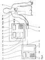
- FIG. 4 is a schematic illustration of an arrangement for controlling or programming a pacemaker system PS from a programming device Pr and a pacemaker PM implanted in a patient Pa.
- the programming device has an operating unit Pr / Op and a display unit Pr / Di, and within the device two setting functions are symbolized by blocks Pr / 1 and Pr / 2.
- Pacemaker PM and programming device Pr are connected to one another via a telemetry unit Tel, via which operating parameter settings made on the programming device are transmitted to the pacemaker.
- a pulse oximeter 1 for detecting blood oxygen saturation is provided as a device for measuring a quantity reflecting the metabolic or hemodynamic state of the patient.
- This includes a measuring probe S which receives a finger 2 of the patient Pa.
- the measuring probe S is connected to an input 1 / I of the pulse oximeter 1, and this is connected via an output 1 / O to an input Pr / I of the programming unit Pr of the pacemaker system PS.
- the pulse oximeter 1 is shown in more detail in FIGS. 7 to 11 and is described in detail in the associated part of the description.
- a display unit 1.6 and an operating unit 1.7 are shown individually from the structure thereof;
- the assemblies 1.1 to 1.5 shown in FIG. 7 are symbolized in FIG. 4 as a block (shown in broken lines).
- a measured value and setting memory 1 / M is provided in the pulse oximeter 1.
- the first external i.e. Via the programming unit Pr, the setting function Pr / 1 to be implemented, which is related to the hemodynamic state of the patient Pa, is called, for example the setting of the stimulation rate.
- a measurement series is formed with the setting valid until the examination and other basic settings provided in the system.
- a setting value is transmitted to the pacemaker PM via the telemetry unit Tel and the heart H of the patient Pa is stimulated with this value by the pacemaker over a period of time specified on the programming device Pr.
- the pulse oximeter 1 uses the measuring probe S to measure the blood oxygen saturation, and the blood oxygen saturation value obtained for the set stimulation rate value is assigned to the rate value in Programming device saved, the number of the measurement in the series of measurements or directly the rate or frequency value can serve as an address.
- the next value of the stimulation rate is then called up and the procedure described is repeated for it.
- the transmission current automatically set during the measurement for the LEDs (not shown in FIG. 4) is stored in the measuring probe S under the patient's name, so that in later analog tests on the same patient immediately from the correct settings of the sensor arrangement can be assumed.
- the highest value of blood oxygen saturation is automatically determined (in the manner described in more detail below), stored in the internal memory 1 / M of pulse oximeter 1 under the patient's name and the associated rate value via the programmer Pr transmitted to the pacemaker PM as the new, final setting value for the patient's exercise level examined with the series of measurements.
- the second setting Pr / 2 for example the AV delay of a two-chamber pacemaker PM (which is described in more detail below) at one or more predetermined rate value (s), can be optimized in a further series of measurements or series of series of measurements.
- the control of the pacemaker then takes place in such a way that an activity or stress sensor assigned to it is implanted Signal is issued, from which the above-mentioned identifier for the load state is obtained, and that the associated stored rate and AV delay value is set. (This is also explained in more detail below.)
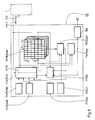
- FIG. 5 is a highly simplified block diagram to illustrate the structure and function of the programming device Pr in a (functionally slightly modified) configuration according to FIG. 4.
- the arrangement differs from the one described above in that it also optimizes the rate and AV delay time a changed process allowed.
- the heart of the programming device Pr is a microprocessor unit Pr / CPU, which in a manner known per se is associated with a program memory Pr / ROM and a data memory Pr / RAM and, as already shown in FIG. 4, a display unit Pr / Di and a control panel Pr / Op are.
- An auxiliary memory Pr / MAux which is organized in several levels in a matrix-like manner, is of particular importance for carrying out the check / readjustment of the pacemaker operating parameters (AV delay and stimulation rate selected here as an example).
- Its column addresses are the individual stimulation frequency values f 1 ... f n available in the data memory Pr / RAM under specification for the implanted pacemaker and its row addresses are the respectively available AV delay values AV 1 ... AV n .
- the memory levels here stand for the individual measurements of a combined rate / AV delay measurement series.
- the blood oxygen saturation value SaO2 measured for a specific combination of frequency and AV delay value is stored in a respectively addressed memory field stored. (For an overall presentation and details of the organization and handling of such memories for operating parameter maps, reference is made to EP-B-0 222 681 here.)
- the programming device Pr has a comparator unit Pr / Com connected on the input side to the data output of the auxiliary memory Pr / MAux and on the output side with an operating parameter register Pr / Reg for evaluating the measured values of the blood oxygen saturation. It also includes a criteria read-only memory (ROM) Pr / MCri connected to a control input of the comparator unit Pr / Com for storing one or more comparison criteria or values as the basis for evaluating the blood oxygen saturation, and one - in the figure as part of the Pr / CPU shown - timing control Pr / Ti for the execution of the measurements and the subsequent comparison procedure.
- ROM read-only memory
- the procedure described above with reference to FIG. 4 is practiced for readjusting or calibrating the pacemaker;
- the stimulation rate and AV delay are not optimized successively in two separate series of measurements, but rather (quasi "two-dimensionally") in one series of measurements.
- An operating mode and an operating parameter correlation - in this case the correlation f / AV - are preselected via the control panel Pr / Op of the programming device and read from the program memory Pr / ROM.
- the sets f 1 ... f n and AV 1 ... AV m automatically become available operating parameters from the data memory Pr / RAM read out and the current organization of the auxiliary memory Pr / MAux specified.
- the preselected pair of parameters is transferred to the Pr / Reg operating parameter register and transmitted to the pacemaker PM via the telemetry system Tel.
- the pulse generator is set for a specific period of time specified by the time control unit Pr / Ti of the programming device (the course of which is signaled by the telemetry unit simply by transmitting a new pair of parameters).
- the blood oxygen saturation is measured in the manner described below and the measured value at the address ( f i , AV i ) in the auxiliary memory Pr / MAux and simultaneously (together with the current parameters) shown on the display device Pr / Di for the doctor.
- the results of the comparison can be shown on the display unit Pr / Di.
- the associated address is loaded into the operating parameter register Pr / Reg, so that at the end of the comparison procedure, the address in this register that belongs to the highest SaO 2 value and the represents the optimal operating parameter combination f / AV for the underlying load condition. This is shown on the display unit Pr / Di and transmitted to the pacemaker via the telemetry unit, where it is stored (as explained in more detail below).
- the pacemaker for the selected operating mode contains a hemodynamically optimized set of parameter pairs (f k , AV k ) , based on which the load-dependent control of the pacemaker can take place in the future.
- FIG. 6 shows a simplified block diagram of an AV sequential two-chamber pacemaker 201, which can be set or calibrated with an arrangement according to an embodiment of the invention
- the core element is a control unit 202, to which a circuit 203 for "run-away" protection and a program decoder 204 are directly assigned.
- a battery 205 with a downstream EOL indicator 206 supplies the modules with energy.
- a program and operating data register 212 is loaded via a receiver coil 208, a receiver 209, a program amplifier 210 and a safety circuit 211 for program checking, from which program data can be queried by the control unit 202.
- the program register is loaded via a programming device with a telemetry unit, as is sketched in FIG. 5.
- a pacemaker K is assigned to the pacemaker 201, which comprises a (right) atrial and a (right) ventricular electrode arrangement EA or EV with conventional sensing and stimulation functions. Furthermore, an activity sensor Act, which is also known as such, is assigned to it, which emits signals representing the physical activity of the patient and thus his or her load.
- Heart action potentials are detected via the electrode arrangements EA and EV and via an input amplifier 213 for atrial signals and an input amplifier 214 for ventricular signals (each with downstream fault detection circuit 215 or 216) supplied to the control unit 202.
- the measurement signals of the activity sensor Act are fed to an evaluation unit 217.
- the output signal of this unit 217 is also fed to the control unit 202 for pacemaker operation, where it is used for the ongoing setting of the stimulation rate and / or the AV delay in accordance with the metabolic need of the patient corresponding to the proven activity level, while the demand is measured via the cardiac action potentials measured intracardially Operation of the pacemaker 201 is controlled.
- the valid correlation between the parameter pair stimulation rate / AV delay and the load or activity of the patient is set during the periodic follow-up examinations.
- the program and operating parameter memory 212 comprises a memory area which can be freely addressed by output signals from the evaluation unit 217 (i.e. by processed activity signals) and in which the valid f / AV pairs for different load conditions are stored during the examination.
- a memory area is then addressed by the activity signal prepared and the pair of parameters stored therein is called up to control the pulse generator.
- the stimulation pulses generated with corresponding parameters are delivered to the electrode arrangements EA and EV via an output amplifier circuit 218 and 219, respectively, and are transmitted from there to the excitable heart tissue.
- Blood oxygen saturation can of course also be used to optimize only one pacemaker operating parameter - for example the AV delay alone at a given stimulation rate - and the pacemaker can be programmed by further measurements using other methods (e.g. physical activity directly, impedance measurements, etc.) be additionally supported.
- other methods e.g. physical activity directly, impedance measurements, etc.
- FIG. 7 is a simplified block diagram of a device 1 for the extracorporeal determination of blood oxygen saturation, in the figure on a finger 2.
- the device comprises a transmission stage 1.1 with a transmitter-side red channel 1.1a and a transmitter-side infrared channel 1.1b and a reception stage 1.2 with a receiver-side red channel 1.2a and a receiver-side infrared channel 1.2b.
- the receiver and the transmitter-side red or infrared channels 1.1a and 1.2a or 1.1b and 1.2b form two separate measuring channels 1a and 1b for determining the transmission with visible light with a wavelength of 660 or with infrared radiation with one 950 nm wavelength.
- the transmitter stage includes one emitting at 660 nm, i.e. red-lit LED 3a with a direct voltage supply 4a and an alternating voltage supply 5a for tone-frequency (1 kHz) modulation of the emitted light in the first channel 1a.
- red-lit LED 3a with a direct voltage supply 4a and an alternating voltage supply 5a for tone-frequency (1 kHz) modulation of the emitted light in the first channel 1a.
- it comprises an LED 3b emitting infrared at 950 nm with a direct voltage supply 4b and an alternating voltage supply 5b for 1 kHz modulation of the emitted IR radiation in the second channel 1b.
- the radiation of both LEDs is in a distance range A of a (not shown in the figure) housing, in which the Finger 2 is inserted, emitted and picked up by a photodetector (a PIN diode) 6a or 6b opposite the LED 3a or 3b.
- An optical bandpass filter 7a is connected upstream of the photodetector 6a in the red channel 1a.
- the signals supplied by the respective photodetectors 6a and 6b subsequently run through analog processing paths. They are first amplified in an amplifier 8a or 8b, after which the signal path branches.
- a first signal path leads through a 40 Hz low-pass filter 9a or 9b and a 0.1Hz high-pass filter 10a or 10b and delivers a plethysmogram or.
- a quotient formation in a subordinate arithmetic processing stage 1.3 provides approximately a value from this, from which SaO2 can be read using the curve shown in FIG. 3.
- a second signal path leads through a 1 kHz bandpass filter 11a or 11b, at the output of which a first correction signal S C1 (R) or S C1 (IR) is continuously available to determine the transmission efficiency of the sample (finger 2). This is done by comparing the received amplitude of the 1 kHz pilot signal with the original, modulated pilot signal in a first pilot signal processing and comparator unit 1.4a or 1.4b.
- a third signal path leads through a 3 kHz bandpass filter 12a or 12b, at the output of which a second correction signal S C2 (R) or S C2 (IR) is available, which is used to detect harmonic distortions due to non-linear operation of the components can. This happens again by comparative processing with the original 1 kHz signal in a second pilot signal processing and comparator unit 1.5a and 1.5b, respectively.
- the evaluation of the transmission efficiency also makes it possible to have standardized data available for measurements on a patient at different times and for measurements on a patient population.
- the transmission data obtained in both channels can be stored in a patient file for a patient and previous values can be passed with the values of current measurements.
- S C2 (R ) or S C2 (IR) a control device (not shown in the figure) is actuated, which controls the direct current supply 4a or 4b in such a way that the LED current for the LEDs 3a or 3b is calibrated in predetermined steps until none Distortion no longer occurs, ie no signal S C2 (R) or S C2 (IR) can be detected.
- This setting can also be saved for a special patient in his patient file so that this setting can be started in a later examination.
- the measuring probe is not connected or the probe cable is defective, and the operator is shown appropriate information on the display 1.6.
- FIG. 8 shows a connection diagram and component specifications for the actual measuring probe according to FIG. 7 (slightly modified by using three LEDs in the red and infrared channels).
- the reference numerals are - except for the corresponding replacement of the numbers 3a by 3a 'or 3b by 3b' - the same as in Fig. 7, and the circuit as such will not be described again.
- the first four signals can be transmitted on a double line with simple shielding, the shielding of which is connected to a central 0V reference point.
- Minimal crosstalk is achieved through a 180 ° phase shift between the red and infrared pilot tones.
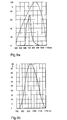
- FIGS. 9a and 9b are representations of the sensitivity curves of the red and IR reception component 6a (with an upstream optical filter 7a) and 6b (with an integrated optical filter) of the device shown in FIG. 7.
- a PIN diode Siemens BPW34 is used as detector 6a in the red channel la, the spectral sensitivity curve of which has the shape of the dashed curve in FIG. 9a. It can be seen that the detector is sensitive in the wavelength range from approximately 400 to approximately 1100 nm, while detection is only required around 660 nm and that the sensitivity in the short as well as in the longer wavelength range deteriorates the measuring accuracy of the device.
- the detector is therefore equipped with an Edmund Scientific G39.424 IR cut filter and a filter to suppress shorter wavelengths, such as the Siemens BPW21 photodetector. Overall, the solid transmission curve then results with the composite filter 7a.
- 9b shows the spectral sensitivity curve of the Siemens BPW34F PIN diode used as an IR detector with an integrated daylight filter. It can be seen that there is practically no transmission below 750 nm, so that excellent channel separation red-infrared and almost complete insensitivity to interference from visible light is achieved.
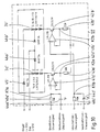
- FIG. 10 is a detailed illustration of the LED control in a pulse oximeter 1 ′ modified with respect to the device according to FIG. 7, of which only the transmission stage 1.1 ′ is shown in FIG. 10.
- the reception stage can be designed according to FIG. 7 or FIG. 11 explained below.
- the transmission stage comprises a red transmitter group 3a 'and an infrared transmitter group 3b' each consisting of three LEDs.
- the specification of the transmit components (as for the other components) is given in the figure.
- the red and infrared channels have separate voltage-controlled current sources.
- a direct current control signal (10 mA / V for red, 15 mA / V for infrared) is fed via a resistor 40a 'or 40b' and a node K1a or K1b to the non-inverting input of an operational amplifier 41a 'or 41b', whose inverting input is connected via a node K2a or K2b on the one hand to the emitter of an npn transistor 42a 'or 42b' and on the other hand via a resistor 43a 'or 43b' to ground.
- An alternating current control signal (for the 1 kHz pilot signal) is also supplied to the non-inverting via the capacitor 44a 'or 44b' via the node K1a or K1b Input of the operational amplifier 41a 'or 41b' supplied.
- the outputs of the operational amplifiers 41a 'and 41b' are each connected to the base of the transistors 42a 'and 42b'.
- the collectors of the transistors 42a 'and 42b' are either via the (complete) transmitter element group 3a 'or 3b' and a diode 45 'with a + 12V supply voltage ("Bright") or - if only two LEDs are used - connected to the + 12V supply voltage ("Dim”) via two LEDs of the transmitter element group and one diode 46a 'or 46b' each.
- the operational amplifiers 41a ', 41b' control the collector current and thus the operating current of the LED groups 3a 'and 3b' as a function of the applied direct and alternating current control signals in a manner known per se via the transistors 42a ', 42b' in a basic circuit.
- FIG. 11 is a partial representation of the reception stage, especially the evaluation circuit, of a pulse oximeter somewhat modified compared to the device according to FIG. 7, both channels being constructed in the same way and only the red channel 1 a 'being shown here. 7 is the guidance of the measurement signal coming from the PIN diode 6a over three separate signal paths, which are designated in FIG. 11 with 1.21 ', 1.22' and 1.23 'and on which output signals S O (R) , S c1 (R) or S C2 (R) can be supplied.
- In signal path 1.21 ' is one of a resistor 80a', a further resistor 81a ', a capacitor 82a' connected in parallel with this, a capacitor 83a 'separating resistor 81a' from ground, an operational amplifier 84a 'and two further resistors 85a' and 86a ' Low-pass filter and amplifier circuit are provided, the non-inverting input of operational amplifier 84a 'being connected in series with one another through resistors 80a' and 81a 'to the output of the photodetector and via capacitor 83a' to ground, its inverting input being connected via resistor 85a ' to ground and its output through resistor 86a 'to ground, through capacitor 82a' to the junction between series resistors 80a 'and 81a' and to the next processing stage.
- FIG. 11 shows the connection of the operational amplifier (and also of the further operational amplifiers described further below) to the power supply and - via two capacitors not provided with reference numbers - to ground.
- the signal passes into a capacitor 100a', a further capacitor 101a ', a series circuit made up of two resistors 102a', 103a 'parallel to the latter, and a series circuit made up of two resistors separating the capacitor 101a' from ground 104a ', 105a', an operational amplifier 106a 'and two further resistors 107a' and 108a 'formed high-pass filter and amplifier circuit, in which the non-inverting input of the operational amplifier 106a' via the capacitors connected in series with the input of this stage and over resistors 104a ', 105a' to ground, its inverting input through resistor 107a 'to ground and its output through resistor 108a' to ground and through series resistors 102a ', 103a' to the connection point between the capacitors 100a ', 101a' is connected and simultaneously forms the output of the first signal path 1.21 '.
- the operational amplifier circuit shown realizes - in addition to the 40 Hz low pass and the 0.1 Hz high pass as a filter with approximate Bessel characteristics and low phase distortions - a NIC converter ("Transimpedance Amplifier") with which the non-linearity of the optical components in a certain Way is compensated.
- a NIC converter Transimpedance Amplifier
- the second and third signal paths 1.22 'and 1.23' are constructed in the same way and differ only in the dimensioning of the components (indicated in the figure), so that in the figure only the second signal path is provided with reference numbers and only this is described here.
- It contains a resistor 110a ', a parallel connection of two capacitors 111a', 112a 'and an operational amplifier 113a', the inverting input of which via the aforementioned elements is connected on the one hand to the input of the stage and on the other hand with an RC parallel circuit 114a ' is connected and its non-inverting input is connected to ground via the tap of a potentiometer 115a '.
- the output of the operational amplifier 113a ' is connected to ground on the one hand via a resistor 116a' and the potentiometer 115a 'and is connected on the one hand to the parallel RC circuit 114a' and on the other hand to the input of a forward-connected diode 117a '. Its output - separated from ground by an RC parallel circuit consisting of an electrolytic capacitor 118a 'and a resistor 119a' - forms the output of the signal path 1.22 '.
- Deviations from the circuits shown are possible for the person skilled in the art at any time, whereby the principle of the detection of harmonic distortions can also be modified via a pilot signal.
- the embodiment of the invention is not limited to the preferred exemplary embodiment specified above. Rather, a number of variants are conceivable which make use of the solution shown, even in the case of fundamentally different types.
Abstract
Description
Die Erfindung betrifft eine Anordnung der im Oberbegriff des Anspruchs 1 angegebenen Art.The invention relates to an arrangement of the type specified in the preamble of
Es ist seit langem üblich, die Programmierung eines extern programmierbaren Herzschrittmachers unter Zuhilfenahme eines - insbesondere auch bei unterschiedlichen physischen Belastungen - extrakorporal aufgenommenen EKG mittels eines Programmiergerätes vorzunehmen, wobei der Arzt die Betriebsparameter des Schrittmachers im Hinblick auf die aus dem EKG gewinnbaren Aussagen optimal einzustellen versucht.It has long been common practice to program an externally programmable cardiac pacemaker with the aid of an ECG, which is recorded extracorporeally, especially with different physical loads, using a programming device, the doctor trying to optimally set the operating parameters of the pacemaker with regard to the statements that can be obtained from the ECG .
Das EKG reflektiert jedoch nur sehr bedingt und indirekt den Zustand des metabolischen bzw. hämodynamischen Systems des Patienten, so daß eine derart vorgenommene Einstellung vielfach nicht wirklich optimal ist. Der Einstellvorgang ist zudem für den Arzt bedien- und zeitaufwendig und birgt Fehlerquellen in sich.However, the EKG reflects the condition of the patient's metabolic or hemodynamic system only to a very limited extent and indirectly, so that an adjustment made in this way is often not really optimal. The adjustment process is also time-consuming for the doctor and harbors sources of error.
Es ist bekannt, daß bestimmte physikalische oder chemische Größen - etwa die Blutsauerstoffsättigung oder der pH-Wert des Blutes - den hämodynamischen Zustand eines Menschen recht gut widerspiegeln, und diese werden auch zur Steuerung von Herzschrittmachern herangezogen.It is known that certain physical or chemical parameters - such as blood oxygen saturation or the pH of the blood - reflect the hemodynamic state of a person quite well, and these are also used to control pacemakers.
Eine Vorrichtung zur Bestimmung der Blutsauerstoffsättigung, die speziell zur intrakardialen Verwendung ausgebildet ist und deren Meßwerte zur Frequenzsteuerung eines Herzschrittmachers herangezogen werden sollen, ist in DE 31 52 963 C1 beschrieben. Diese Vorrichtung umfaßt eine Meßsonde mit einer rot-emittierenden Leuchtdiode (LED) und einem Fototransistor sowie eine Ansteuer- und Signalwandlerschaltung, in der der empfangenen (Rot-)Lichtintensität proportionale Fotostrom unter Zuhilfenahme eines Referenzsignals in ein die Rot-Transmission des Blutes repräsentierendes elektrisches Signal umgewandelt wird. Dieses ist ein Ausdruck der Blutsauerstoffsättigung und damit des hämodynamischen Zustandes des Patienten und kann für die Schrittmachersteuerung genutzt werden.A device for determining blood oxygen saturation, which is specially designed for intracardiac use and whose measured values are to be used for frequency control of a pacemaker, is described in DE 31 52 963 C1. This device comprises a measuring probe with a red-emitting light-emitting diode (LED) and a photo transistor as well as a control and signal converter circuit in which the received (red) light intensity proportional photo current is converted with the aid of a reference signal into an electrical signal representing the red transmission of the blood. This is an expression of the blood oxygen saturation and thus the hemodynamic state of the patient and can be used for pacemaker control.
Das Referenzsignal wird hier in einer zweiten Messung mit umgekehrter Spannungs-Polarität gewonnen, bei der durch eine hierzu vorgesehene Diode im Meßkreis der spezifische Meßsignalanteil eliminiert wird. Der Vergleich von Meß-und Referenzsignal liefert dann den spezifischen Signalanteil.The reference signal is obtained here in a second measurement with reverse voltage polarity, in which the specific measurement signal component is eliminated by a diode provided for this purpose in the measuring circuit. The comparison of the measurement and reference signal then provides the specific signal component.
Das Meßverfahren nach DE 31 52 983 hat den entscheidenden Nachteil, daß die Transmissions- bzw. Reflexionsmessung bei einer einzelnen Meß-Wellenlänge lediglich eine Relativmessung darstellt, mit der zwar Veränderungen der Blutsauerstoffkonzentration, jedoch nicht deren Absolutwert bestimmt werden können. Die Steuerung eines Schrittmachers mit den bei diesem Verfahren gewonnenen Werten kann daher nur eine Trend-Steuerung sein, eine Einstellung von Ausgangswerten bzw. eine Eichung der Betriebsparameter mußte dabei aufgrund anderer Größen erfolgen.The measuring method according to DE 31 52 983 has the decisive disadvantage that the transmission or reflection measurement at a single measuring wavelength is only a relative measurement, with which changes in the blood oxygen concentration but not its absolute value can be determined. The control of a pacemaker with the values obtained in this method can therefore only be a trend control; an adjustment of output values or a calibration of the operating parameters had to be carried out on the basis of other variables.
Zur Darstellung der physiologischen Zusammenhänge dienen die Figuren 1 bis 3. Von diesen zeigen:
Figur 1 eine grafische Darstellung des spektralen Absorptionsvermögens von Deoxy-Hämoglobin (Hb) und Oxy-Hämoglobin (HbO2),Figur 2 eine grafische Darstellung des Absorptionsvermögens von Blut bei 660 nm und bei 950 nm in Abhängigkeit von der Sauerstoffsättigung,Figur 3 eine grafische Darstellung zum relativen Absorptionsvermögen von Blut in Abhängigkeit von der Sauerstoffsättigung.
- FIG. 1 shows a graphic representation of the spectral absorption capacity of deoxy-hemoglobin (Hb) and oxy-hemoglobin (HbO 2 ),
- FIG. 2 shows a graphic representation of the absorption capacity of blood at 660 nm and at 950 nm as a function of the oxygen saturation,
- Figure 3 is a graphical representation of the relative absorbance of blood as a function of oxygen saturation.
Zur Durchführung einer Absolutmessung der Blutsauerstoffsättigung können die im längerwelligen sichtbaren Bereich und im nahen Infrarot stark unterschiedlichen spektralen Absorptionskurven von Deoxy-Hämoglobin (Hb) und Oxy-Hämoglobin (HbO2) dienen, die in Fig. 1 gezeigt sind.The spectral absorption curves of deoxy-hemoglobin (Hb) and oxy-hemoglobin (HbO 2 ), which are very different in the longer-wave visible range and in the near infrared and are shown in FIG. 1, can be used to carry out an absolute measurement of the blood oxygen saturation.
In der Figur ist zu erkennen, daß das spektrale Absorptionsvermögen von Hb wie auch von HbO2 bei 660 bis 670 nm nahezu konstant ist, wobei der Absorptionskoeffizient von Hb hier sehr viel höher ist als derjenige von HbO2. Bei etwa 810 nm ist das Absorptionsvermögen gleich groß und oberhalb dieser Wellenlänge absorbiert HbO2 stärker. Eine Vergleichsmessung bei einer Wellenlänge oberhalb von 810 nm gegenüber einer Primär-Messung bei etwa 660 nm ist daher für die Bestimmung des HBO2-Anteils und damit der absoluten Blutsauerstoffsättigung mit hoher Genauigkeit vorteilhaft.In the figure it can be seen that the spectral absorption capacity of Hb as well as of HbO 2 is almost constant at 660 to 670 nm, the absorption coefficient of Hb here being very much higher than that of HbO 2 . At around 810 nm, the absorption capacity is the same and above this wavelength HbO 2 absorbs more strongly. A comparison measurement at a wavelength above 810 nm compared to a primary measurement at about 660 nm is therefore advantageous for determining the HBO2 content and thus the absolute blood oxygen saturation with high accuracy.
Fig. 2 ist eine grafische Darstellung des relativen Absorptionsvermögens bei 660 nm sowie bei 950 nm in Abhängigkeit von der Blutsauerstoffsättigung SaO2.FIG. 2 is a graphical representation of the relative absorbance at 660 nm and at 950 nm as a function of the blood oxygen saturation SaO 2 .
Fig. 3 ist eine vom Informationsgehalt im Prinzip zu Fig. 3 äquivalente Darstellung, bei der der Quotient aus Infrarot(IR)- und Rot(R)-Absorption bei den genannten Wellenlängen über SaO2 aufgetragen ist. Die Kreuze bezeichnen Werte des Quotienten in 10%-Schritten, und diese wurden in der Figur durch Geraden verbunden; die eigentliche Funktionskurve ist eine Hyperbel.FIG. 3 is a representation equivalent to the information content in principle to FIG. 3, in which the quotient of infrared (IR) and red (R) absorption is plotted against SaO 2 at the wavelengths mentioned. The crosses denote values of the quotient in 10% steps, and these were connected by straight lines in the figure; the actual function curve is a hyperbola.
Aus EP 0 257 954 B1 ist eine Weiterentwicklung des Meßverfahrens und der Meßanordnung nach DE 31 52 993 bekannt, die offensichtlich die vorstehend beschriebenen Zusammenhänge ausnutzt und bei der nunmehr ein Zwei-Wellenlängen-Reflexionsoximeter in einer Schrittmacherleitung integriert ist, dessen Ausganggsignale die tatsächliche Blutsauerstoffsättigung reflektieren und zu einer verbesserten Steuerung eines Bedarfsschrittmachers dienen.From
Die Meßanordnung umfaßt einen Fotodetektor, der gleichermaβen zum Nachweis der Transmission im roten und im infraroten Spektralbereich genutzt wird. Dies erfordert jedoch einen hohen Aufwand bei der Ansteuerung der Meßanordnung und das Vorsehen von Meßsignalspeichern.The measuring arrangement comprises a photodetector, which is used equally for the detection of the transmission in the red and in the infrared spectral range. However, this requires a great deal of effort in the control of the measuring arrangement and the provision of measuring signal memories.
Aus US 4 712 179 sind ein Verfahren und eine Vorrichtung zur Korrektur der über intrakardiale Meßanordnungen im Zusammenwirken mit einem implantierten Schrittmacher gewonnenen Meßwerte unter Zuhilfenahme eines externen Programmier- und Auswertungsgerätes bekannt. Hiermit erfolgt eine Befreiung intrakardial aufgenommener Meßwerte von Verfälschungen, die aus ungenauer Dimensionierung von Dickschicht-Widerständen bei der Herstellung der Schrittmacherschaltkreise resultieren, indem für jeden hergestellten Schrittmacher exemplarspezifische Korrekturwerte ermittelt, in einem ROM-Speicher im Schrittmacher gespeichert, bei der Übertragung der Meßwerte an das Programmier- und Auswertungsgerät mit übertragen und in diesem zur Berechnung korrigierter Meßwerte herangezogen werden.US Pat. No. 4,712,179 discloses a method and a device for correcting the measurement values obtained via intracardiac measurement arrangements in cooperation with an implanted pacemaker with the aid of an external programming and evaluation device. This frees intracardially recorded measurement values from falsifications which result from inaccurate dimensioning of thick-film resistors in the manufacture of the pacemaker circuits, by determining sample-specific correction values for each pacemaker produced, stored in a ROM memory in the pacemaker when the measurement values are transferred to the The programming and evaluation device is also transmitted and used to calculate corrected measured values.
Der Erfindung liegt die Aufgabe zugrunde, eine Anordnung der eingangs genannten Gattung anzugeben, mit der eine Einstellung bzw. Eichung eines Herzstimulators aufgrund von über eine externe Meßvorrichtung gewonnenen, den metabolischen Zustand des Patienten zuverlässig reflektierenden Meßwerten möglich ist und die konstruktiv einfach und variabel ausgebildet und vielfältig eingesetzt werden kann.The invention has for its object to provide an arrangement of the type mentioned with which an adjustment or calibration of a heart stimulator based on Measured values obtained via an external measuring device that reliably reflect the metabolic state of the patient are possible and can be designed in a structurally simple and variable manner and can be used in a variety of ways.
Diese Aufgabe wird durch eine Anordnung mit den Merkmalen des Anspruchs 1 gelöst.This object is achieved by an arrangement with the features of
Die Erfindung schließt den Gedanken ein, Betriebsparameter eines Herzstimulators - Herzschrittmachers oder Defibrillators bzw. Kardioverters - aufgrund von mit hinreichender Genauigkeit extern gewonnenen Absolutwerten einer für den metabolischen Zustand des Patienten repräsentativen, nicht-elektrischen Größe im Zuge eines Programmiervorganges vorzugeben bzw. zu eichen und ein dazu geeignetes automatisches System anzugeben. Diese Parameter können insbesondere die Stimulationsrate und/oder die AV-Verzögerungszeit sein.The invention includes the idea of specifying or calibrating and calibrating operating parameters of a cardiac stimulator - cardiac pacemaker or defibrillator or cardioverter - based on absolute values obtained externally with sufficient accuracy, in the course of a programming process, of a non-electrical variable representative of the patient's metabolic state to specify a suitable automatic system. These parameters can in particular be the stimulation rate and / or the AV delay time.
Die Erfindung schließt weiter das Vorsehen einer Meßvorrichtung ein, in der mit einem sichtbares Licht aussendenden und einem das sichtbare Licht empfangenden Bauelement ein erster Meßkanal sowie mit einem Infrarotstrahlung aussendenden und einem diese empfangenden Bauelement ein zweiter, vom ersten getrennter, Meßkanal gebildet ist. Sie schließt weiter den Gedanken ein, die Steuer- und Auswertungseinrichtung des Meßgerätes so auszubilden, daß beide Meßkanäle gleichzeitig betrieben und die darin gewonnenen Meßsignale im wesentlichen gleichzeitig verarbeitet werden können. Damit kann auf Umschaltungen und Signal-Zwischenspeicherungen grundsätzlich verzichtet werden, womit Fehlerquellen eliminiert werden und ein schneller und störungsarmer Betrieb gewährleistet wird.The invention further includes the provision of a measuring device in which a first measuring channel is formed with a component emitting visible light and a component receiving the visible light, and a second measuring channel is formed with a component emitting infrared radiation and a component receiving it. It also includes the idea of designing the control and evaluation device of the measuring device in such a way that both measurement channels can be operated simultaneously and the measurement signals obtained therein can be processed essentially simultaneously. This means that switchovers and intermediate signal storage can be dispensed with, which eliminates sources of error and ensures fast and trouble-free operation.
Die Steuer- und Auswertungseinrichtung des Meßgerätes kann damit so ausgebildet werden, daß die Meßsignale zeitnah (on-line) verarbeitet werden können. Dies ermöglicht die schnelle Aufnahme von Meßkurven zur Änderung der Blutsauerstoffsättigung - oder einer anderen repräsentativen Meßgröße - in Reaktion auf die Variation von Betriebsparametern des Herzstimulators und damit eine zügige Optimierung der entsprechenden Parameter anhand der Meßwerte.The control and evaluation device of the measuring device can thus be designed such that the measurement signals can be processed promptly (on-line). This enables the rapid recording of measurement curves for changing the blood oxygen saturation - or another representative measurement variable - in response to the variation in operating parameters of the heart stimulator and thus a rapid optimization of the corresponding parameters on the basis of the measurement values.
Die Genauigkeit der Meßwerte wird - für den Fall der Meßgröße Blutsauerstoffsättigung - dadurch weiter erhöht, daß die aussendenden und/oder die empfangenden Bauelemente so ausgebildet und/oder derart mit Filtermitteln versehen sind, daß das Spektrum des empfangenen Lichts und dasjenige der empfangenen Infrarotstrahlung im wesentlichen keinen Überlappungsbereich aufweisen. Je ausgeprägter die Trennung der beiden Meßbereiche ist, desto größer kann angesichts der in Fig. 1 dargestellten Absorptionskurven die Meßgenauigkeit sein.The accuracy of the measured values - in the case of the measured variable blood oxygen saturation - is further increased in that the emitting and / or the receiving components are designed and / or provided with filter means in such a way that the spectrum of the received light and that of the received infrared radiation essentially have no overlap area. The more pronounced the separation of the two measuring ranges, the greater the measuring accuracy can be in view of the absorption curves shown in FIG. 1.
Die Erfindung schließt dazu weiter den Gedanken ein, einen Eingang des Programmiergerätes mit dem Ausgang einer Steuer- und Auswertungseinrichtung für die nicht-elektrische Größe - etwa die Blutsauerstoffsättigung - zu verbinden und das Programmiergerät mit Mitteln zur selbsttätigen Durchführung und Auswertung einer Meßreihe für die nicht-elektrische Größe in Abhängigkeit von verschiedenen, über die Telemetrieeinrichtung am Herzstimulator eingestellten Werten des Betriebsparameters und Festlegung eines optimierten Betriebsparameters entsprechend dem Auswertungsergebnis der Meßreihe zu versehen.To this end, the invention further includes the idea of connecting an input of the programming device to the output of a control and evaluation device for the non-electrical variable - such as blood oxygen saturation - and the programming device with means for automatically carrying out and evaluating a series of measurements for the non- electrical variable as a function of various values of the operating parameter set on the heart stimulator via the telemetry device and definition of an optimized operating parameter in accordance with the evaluation result of the series of measurements.
Diese Mittel umfassen in zweckmäßigen Ausgestaltungen einen, insbesondere als Matrixspeicher ausgeführten, Hilfsspeicher zur Speicherung von Meßwerten der nicht-elektrischen Größe in Zuordnung zu Betriebsparemeterwerten, nach deren Einstellung sie aufgenommen wurden, eine Vergleichereinheit zur Auswertung der Meßwerte der nicht-elektrischen Größe mit Hilfe von in einem, mit einem Steuereingang der Vergleichereinheit verbundenen, Kriterien-Festwertspeicher zur Speicherung mindestens eines Vergleichskriteriums für die Auswertung und eine Zeitablaufsteuerung und einen Zähler zur zeitlichen Steuerung des Ablaufs einer Meßreihe derart, daß in einem vorbestimmten Zeittakt in vorbestimmter Folge verschiedene Betriebsparameterwerte am Schrittmacher eingestellt und zusammen mit dem jeweils erhaltenen Meßwert der nicht-elektrischen Größe ausgegeben bzw. gespeichert werden.In expedient refinements, these means comprise an auxiliary memory, in particular in the form of a matrix memory, for storing measured values of the non-electrical variable in association with operating parameter values after their setting, a comparator unit for evaluating the measured values of the non-electrical variable with the aid of in a criteria read-only memory connected to a control input of the comparator unit for storing at least one comparison criterion for the evaluation and a time sequence control and a counter for time control of the sequence of a series of measurements such that different operating parameter values are set and put together on the pacemaker in a predetermined time cycle in a predetermined sequence are output or stored with the respectively obtained measured value of the non-electrical quantity.
Die Meßanordnung ist insbesondere so ausgebildet, daß die Ausgangssignale direkt on-line verarbeitet werden können.The measuring arrangement is particularly designed so that the output signals can be processed directly on-line.
Als nicht-elektrische Meßgröße ist insbesondere die Blutsauerstoffsättigung geeignet, wobei ein Meßverfahren anzuwenden ist, das die Bestimmung von deren Absolutwert erlaubt.Blood oxygen saturation is particularly suitable as a non-electrical measured variable, a measuring method being used which allows the determination of its absolute value.
Eine hierfür geeignete Meßanordnung umfaßt mindestens je ein sichtbares Licht sowie Infrarotstrahlung aussendendes Bauelement sowie ein das sichtbare Licht und die Infrarotstrahlung nach Durchgang durch einen durchbluteten Körperbereich empfangendes Bauelement, wobei das das sichtbare Licht aussendende und das dieses empfangende Bauelement einen ersten Meßkanal sowie das die Infrarotstrahlung aussendende und das diese empfangende Bauelement einen zweiten, vom ersten getrennten, Meßkanal bilden und der erste und der zweite Meßkanal gleichzeitig betrieben und die in beiden Meßkanälen erhaltenen Meßsignale im wesentlichen gleichzeitig verarbeitet werden.A measuring arrangement suitable for this purpose comprises at least one component emitting visible light and one emitting infrared radiation, as well as one component receiving the visible light and the infrared radiation after passing through a body area which is supplied with blood, the component emitting the visible light and the component receiving this having a first measuring channel and the component emitting the infrared radiation and the component receiving this receives a second, form from the first separate measurement channel and the first and second measurement channels are operated simultaneously and the measurement signals obtained in both measurement channels are processed essentially simultaneously.
Von Bedeutung für eine gute Kanaltrennung und damit für die Genauigkeit der Absolutmessung ist, daß die aussendenden und/oder die empfangenden Bauelemente so ausgebildet und/oder derart mit Filtermitteln versehen sind, daß die Spektren der jeweisl empfangenen Strahlung im wesentlichen keinen Überlappungsbereich aufweisen.It is important for good channel separation and thus for the accuracy of the absolute measurement that the transmitting and / or the receiving components are designed and / or provided with filtering means that the spectra of the radiation received in each case have essentially no overlap area.
Das sichtbare Licht hat in Anbetracht der in Fig. 1 gezeigten Kurven vorteilhafterweise ein Intensitätsmaximum bei einer Wellenlänge von etwa 660 nm und die Infrarotstrahlung ein Intensitätsmaximum bei einer Wellenlänge von etwa 950 nm.In view of the curves shown in FIG. 1, the visible light advantageously has an intensity maximum at a wavelength of approximately 660 nm and the infrared radiation has an intensity maximum at a wavelength of approximately 950 nm.
Eine kostengünstige und kompakte und damit vielseitige Einsatzmöglichkeiten erschließende Realisierung der optoelektronischen Bauelemente besteht darin, daß die aussendenden Bauelemente mindestens je eine rot- und eine infrarotemittierende LED oder Laserdiode und die empfangenden Bauelemente ein rot- und ein infrarotempfindlicher HalbleiterFotodetektor sind. In einer speziellen, lichtstarken und den störenden Einfluß lokaler Inhomogenitäten des Gewebes bzw. des Blutstromes weitgehend eliminierenden Ausführung sind je drei rot- und infrarotemittierende LEDs bzw. Laserdioden vorgesehen.A cost-effective and compact and thus versatile application of the optoelectronic components is that the emitting components are at least one red and one infrared-emitting LED or laser diode, and the receiving components are red and infrared-sensitive semiconductor photo detectors. In a special, bright light and largely eliminating the disturbing influence of local inhomogeneities of the tissue or the blood flow, three red and infrared emitting LEDs or laser diodes are provided.
Um die oben erwähnte Meßbereichstrennung sowie eine Ausschaltung störender kurzwelliger Strahlungsanteile bei leicht verfügbaren und kostengünstigen Standard-Bauelementen zu realisieren, kann dem das sichtbare Licht empfangenden Bauelement ein optisches Bandfilter und dem die Infrarotstrahlung empfangenden Bauelement ein Filter für kurzwellige Strahlungsanteile zugeordnet sein.In order to implement the above-mentioned measurement range separation and the elimination of disturbing short-wave radiation components with readily available and inexpensive standard components, the visible light can be obtained Component an optical band filter and the component receiving the infrared radiation, a filter for short-wave radiation components can be assigned.
In der Steuer- und Auswertungseinrichtung können in vorteilhafter Weise Mittel zum Erzeugen und Anlegen einer Wechselspannung an die aussendenden Bauelemente zur Modulation der emittierten Strahlung sowie mindestens eine Verarbeitungsstufe zur Auswertung des modulierten Anteils der empfangenen Strahlung vorgesehen sein. Damit ist zum einen die Bestimmung harmonischer Verzerrungen der empfangenen Strahlung und zum anderen die Bestimmung des Transmissionsgrades der empfangenen Strahlung möglich. Dies ermöglicht es, einen Betrieb der Anordnung im nichtlinearen Bereich der Bauelemente (etwa bei Patienten mit sehr "durchscheinender" Haut), der zu einer Verfälschung der Meßwerte führen würde, zu erkennen und durch entsprechende Nachjustierung abzustellen.In the control and evaluation device, means for generating and applying an alternating voltage to the emitting components for modulating the emitted radiation and at least one processing stage for evaluating the modulated portion of the received radiation can advantageously be provided. This enables on the one hand the determination of harmonic distortions of the received radiation and on the other hand the determination of the transmittance of the received radiation. This makes it possible to recognize an operation of the arrangement in the non-linear area of the components (for example in patients with very "translucent" skin), which would lead to a falsification of the measured values, and to switch it off by appropriate readjustment.
Die Verarbeitungsstufen können speziell jeweils ein Bandfilter und eine Gleichrichterstufe, deren Ausgangssignale - je nach Wahl des Filter-Durchlaßbereiches - ein Maß für die harmonischen Verzerrungen oder den Transmissionsgrad des durchstrahlten Gewebes sind, und eine Vergleichereinheit aufweisen, in der das entsprechend verarbeitete Empfangs-Pilotsignal mit dem Sende-Pilotsignal verglichen wird.The processing stages can specifically each have a bandpass filter and a rectifier stage, the output signals of which - depending on the filter passband selection - are a measure of the harmonic distortion or the transmittance of the irradiated tissue, and have a comparator unit in which the correspondingly processed received pilot signal is included the transmit pilot signal is compared.
Die Ergebnisse können dem Bediener angezeigt werden, woraufhin dieser eine manuelle Nachjustierung vornehmen kann. Vorteilhafter ist aber das Vorsehen einer automatischen Justierung des Sendestromes nach Maßgabe der Vergleichsergebnisse auf einen Wert, bei dem die Detektoren in einem annähernd linearen Bereich arbeiten. Die ermittelten Werte bzw. die Justierstellung können patientenbezogen gespeichert und für spätere Messungen verwendet werden.The results can be displayed to the operator, whereupon the operator can carry out a manual readjustment. However, it is more advantageous to provide an automatic adjustment of the transmission current in accordance with the comparison results to a value at which the detectors operate in an approximately linear range. The determined values or the adjustment position can be saved patient-related and used for later measurements.
Im eigentlichen Meß-Signalweg (des unmodulierten Signalanteils) zur Bestimmung der Blutsauerstoffsättigung ist in einer einfachen Ausführung mit kostengünstigen Operationsverstärkern zunächst ein Tiefpaßfilter (etwa mit fgo = 40 Hz) mit einem ersten Operationsverstärker und ein Hochpaßfilter (etwa mit fgu = 0,1 Hz - zur Eliminierung langsamer Nullpunktdrift) mit einem zweitem Operationsverstärker vorgesehen. Die Filter arbeiten vorzugsweise als Bessel-Filter mit minimaler Phasenverzerrung, und die Schaltung kann die Eigenschaften eines NIC-Konverters aufweisen.In the actual measurement signal path (of the unmodulated signal component) for determining the blood oxygen saturation, a low-pass filter (for example with f go = 40 Hz) with a first operational amplifier and a high-pass filter (for example with f gu = 0.1 Hz - to eliminate slow zero drift) with a second operational amplifier. The filters preferably operate as Bessel filters with minimal phase distortion, and the circuit can have the properties of a NIC converter.
Die Meßvorrichtung kann im äußeren Aufbau für die Messung an der Körperoberfläche ausgebildet sein, indem die aussendenden und die empfangenden Bauelemente mit einem Abstandsbereich voneinander in einem (auch flexiblen) Gehäuse angeordnet sind, das zur Aufnahme eines Körperteils, insbesondere eines Ohrläppchens oder Fingers, eines Patienten im Abstandsbereich ausgebildet ist.The measuring device can be designed in the outer structure for the measurement on the body surface, in that the transmitting and the receiving components are arranged with a spacing area from one another in a (also flexible) housing which is used to accommodate a body part, in particular an earlobe or finger, of a patient is formed in the distance area.
Es ist aber auch möglich, die aussendenden und die empfangenden Bauelemente mit einem Abstandsbereich voneinander in einer miniaturisierten Baugruppe anzuordnen, die zur intrakorporalen Messung, insbesondere im Herzen oder in einem größeren Gefäß, ausgebildet ist.However, it is also possible to arrange the transmitting and receiving components with a spacing area from one another in a miniaturized assembly which is designed for intracorporeal measurement, in particular in the heart or in a larger vessel.
Vorteilhafte Weiterbildungen der Erfindung sind in den Unteransprüchen gekennzeichnet bzw. werden nachstehend zusammen mit der Beschreibung der bevorzugten Ausführung der Erfindung anhand der Figuren näher dargestellt. Es zeigen:
Figur 4 eine schematische Darstellung der erfindungsgemäßen Anordnung in einer Ausführungsform,Figur 5 ein vereinfachtes Blockschaltbild zur Verdeutlichung des Zusammenwirkens von Komponenten des Herzschrittmachers und des Programmiergerätes in einer gegenüber Fig. 4 modifizierten Konfiguration,Figur 6 ein vereinfachtes Blockschaltbild eines AV-sequentiellen Zweikammerschrittmachers, der mit einer Anordnung nach einer Ausführungsform der Erfindung eingestellt bzw. geeicht werden kann,Figur 7 ein vereinfachtes Blockschaltbild einer Vorrichtung zur Bestimmung der Blutsauerstoffsättigung als Teil einer Anordnung gemäß einer Ausführungsform,- Figur 8 eine Detaildarstellung der Vorrichtung nach Fig. 7,
Figur 9a und 9b Darstellungen der Empfindlichkeitskurven der Licht- bzw. IR-Empfangs-Bauelemente mit vorgeschaltetem bzw. integriertem optischem Filter bei einer speziellen Ausbildung der in Fig. 7 gezeigten Vorrichtung,Figur 10 eine Detaildarstellung der LED-Ansteuerung bei einer modifizierten Vorrichtung nach Fig. 7 undFigur 11 eine Detaildarstellung der Auswertungsschaltung bei einer modifizierten Vorrichtung nach Fig. 7.
- FIG. 4 shows a schematic illustration of the arrangement according to the invention in one embodiment,
- FIG. 5 shows a simplified block diagram to clarify the interaction of components of the pacemaker and the programming device in a configuration modified compared to FIG. 4,
- FIG. 6 shows a simplified block diagram of an AV-sequential two-chamber pacemaker, which can be adjusted or calibrated with an arrangement according to an embodiment of the invention,
- FIG. 7 shows a simplified block diagram of a device for determining the blood oxygen saturation as part of an arrangement according to one embodiment,
- FIG. 8 shows a detailed illustration of the device according to FIG. 7,
- 9a and 9b representations of the sensitivity curves of the light or IR reception components with an upstream or integrated optical filter in a special embodiment of the device shown in FIG. 7,
- 10 shows a detailed representation of the LED control in a modified device according to FIGS. 7 and
- FIG. 11 shows a detailed representation of the evaluation circuit in a modified device according to FIG. 7.
Figur 4 ist eine schematische Darstellung einer Anordnung zur Steuerung bzw. Programmierung eines Herzschrittmachersystems PS aus einem Programmiergerät Pr und einem in einen Patienten Pa implantierten Schrittmacher PM. Das Programmiergerät weist eine Bedieneinheit Pr/Op und eine Anzeigeeinheit Pr/Di auf, und innerhalb des Gerätes sind zwei Einstellfunktionen durch Blöcke Pr/1 bzw. Pr/2 symbolisiert. Schrittmacher PM und Programmiergerät Pr stehen über eine Telemetrieeinheit Tel, über die am Programmiergerät vorgenommene Betriebsparametereinstellungen an den Schrittmacher übertragen werden, miteinander in Verbindung.FIG. 4 is a schematic illustration of an arrangement for controlling or programming a pacemaker system PS from a programming device Pr and a pacemaker PM implanted in a patient Pa. The programming device has an operating unit Pr / Op and a display unit Pr / Di, and within the device two setting functions are symbolized by blocks Pr / 1 and Pr / 2. Pacemaker PM and programming device Pr are connected to one another via a telemetry unit Tel, via which operating parameter settings made on the programming device are transmitted to the pacemaker.
Als Gerät zur Messung einer den metabolischen bzw. hämodynamischen Zustand des Patienten reflektierenden Größe ist ein Pulsoximeter 1 zur Erfassung der Blutsauerstoffsättigung vorgesehen. Zu diesem gehört eine Meßsonde S, die einen Finger 2 des Patienten Pa aufnimmt. Die Meßsonde S ist an einen Eingang 1/I des Pulsoximeters 1 angeschlossen, und dieses ist über einen Ausgang 1/O mit einem Eingang Pr/I der Programmiereinheit Pr des Schrittmachersystems PS verbunden.A
Das Pulsoximeter 1 ist in den Figuren 7 bis 11 genauer gezeigt und im zugehörigen Teil der Bechreibung ausführlich beschrieben. In Fig.4 ist von dessen Aufbau eine Anzeigeeinheit 1.6 und eine Bedieneinheit 1.7 einzeln gezeigt; die in Fig. 7 darstellten Baugruppen 1.1 bis 1.5 sind in Fig. 4 zuammenfassend als ein (gestrichelt gezeichneter) Block symbolisiert. Weiterhin ist im Pulsoximeter 1 ein Meßwertund Einstellungsspeicher 1/M vorgesehen.The
Das Zusammenwirken des Pulsoximeters 1 mit dem Schrittmachersystem PS bei einer Routineuntersuchung zur Überprüfung der Funktionstüchtigkeit und der Programmparameter des Schrittmachers ist (im Sinne eines Beispiels) wie folgt:The interaction of the
Im Laufe der Überprüfung der Einstellungen des Schrittmachersystems wird über das Bedienfeld Pr/Op die erste extern, d.h. über die Programmiereinheit Pr, zu realisierende Einstellfunktion Pr/1 aufgerufen, die einen Bezug zum hämodynamischen Zustand des Patienten Pa hat, etwa die Einstellung der Stimulationsrate. Mit der bis zur Untersuchung gültigen Einstellung sowie weiteren im System vorgesehenen Grundeinstellungen wird eine Meßreihe gebildet. In jedem Schritt der Meßreihe wird ein Einstellwert über die Telemetrieeinheit Tel an den Schrittmacher PM übertragen und von diesem über eine am Programmiergerät Pr vorgegebene Zeitspanne das Herz H des Patienten Pa mit diesem Wert stimuliert.In the course of checking the settings of the pacemaker system, the first external, i.e. Via the programming unit Pr, the setting function Pr / 1 to be implemented, which is related to the hemodynamic state of the patient Pa, is called, for example the setting of the stimulation rate. A measurement series is formed with the setting valid until the examination and other basic settings provided in the system. In each step of the series of measurements, a setting value is transmitted to the pacemaker PM via the telemetry unit Tel and the heart H of the patient Pa is stimulated with this value by the pacemaker over a period of time specified on the programming device Pr.
Nach Verstreichen einer vorbestimmten Zeitspanne (die für das Pulsoximeter etwa durch Übertragung eines Auslösesignals durch das Programmiergerät signalisiert wird) wird durch das Pulsoximeter 1 über die Meßsonde S eine Messung der Blutsauerstoffsättigung vorgenommen, und der für den eingestellten Stimulationsratenwert erhaltene Blutsauerstoffsättigungswert wird in Zuordnung zum Ratenwert im Programmiergerät gespeichert, wobei die Nummer der Messung in der Meßreihe oder direkt der Raten- bzw. Frequenzwert als Adresse dienen kann.After a predetermined period of time has elapsed (which is signaled for the pulse oximeter, for example by the transmission of a trigger signal by the programming device), the
Danach wird der nächste Wert der Stimulationsrate aufgerufen und das beschriebene Vorgehen für diesen wiederholt.The next value of the stimulation rate is then called up and the procedure described is repeated for it.
Gleichzeitig wird bei den Messungen im Speicher 1/M auch der während der Messung automatisch eingestellte Sendestrom für die (in Figur 4 nicht gezeigten) LEDs in der Meßsonde S unter dem Patientennamen abgelegt, so daß bei späteren analogen Untersuchungen bei demselben Patienten sogleich von den korrekten Einstellungen der Sensoranordnung ausgegangen werden kann.At the same time, during the measurements in the
Nach Abschluß der Meßreihe - bei gleichbleibender Belastung des Patienten - wird (auf weiter unten genauer beschriebene Weise) im Programmiergerät automatisch der höchste Wert der Blutsauerstoffsättigung ermittelt, im internen Speicher 1/M des Pulsoximeters 1 unter dem Patientennamen abgelegt und der zugehörige Ratenwert über das Programmiergerät Pr als neuer, endgültiger Einstellwert für die mit der Meßreihe untersuchte Belastungsstufe des Patienten an den Schrittmacher PM übermittelt.After completing the series of measurements - while the patient's load remains the same - the highest value of blood oxygen saturation is automatically determined (in the manner described in more detail below), stored in the
Auf völlig analoge Weise können, wenn im Rahmen der Untersuchung eine Überprüfung bzw. Eichung der Belastungs-Raten-Kennlinie eines frequenzadaptiven Schrittmachers vorgenommen werden soll, weitere Meßreihen bei veränderter Belastung des Patienten durchgeführt und ausgewertet und der optimierte Ratenwert für jeden Belastungszustand an den Schrittmacher als neue permanente Einstellung übermittelt werden. Im Schrittmacher werden die einzelnen Ratenwerte zusammen mit einer Kennung für den Aktivitäts-bzw. Belastungszustand, dem sie zuzuordnen sind, abgespei-chert und stehen dann für den Normalbetrieb abrufbar zur Verfügung.In a completely analogous manner, if a check or calibration of the load-rate characteristic of a frequency-adaptive pacemaker is to be carried out as part of the examination, further series of measurements can be carried out and evaluated when the load on the patient changes, and the optimized rate value for each load condition can be sent to the pacemaker as new permanent setting will be transmitted. In the pacemaker, the individual rate values together with an identifier for the activity or. The load state to which they are assigned is saved and is then available for normal operation.
Ebenfalls grundsätzlich analog kann in einer weiteren Meßreihe oder Serie von Meßreihen die zweite Einstellung Pr/2, etwa die AV-Verzögerung eines Zweikammerschrittmachers PM (der unten genauer beschrieben wird) bei einem oder mehreren vorgegebenen Ratenwert(en), optimiert werden.Likewise, basically analogously, the second setting Pr / 2, for example the AV delay of a two-chamber pacemaker PM (which is described in more detail below) at one or more predetermined rate value (s), can be optimized in a further series of measurements or series of series of measurements.
Nach der erfolgten Neueinstellung erfolgt die Steuerung des Schrittmachers dann derart, daß über einen ihm zugeordneten, implantierten Aktivitäts- oder Belastungssensor ein Signal abgegeben wird, aus dem die oben erwähnte Kennung für den Belastungszustand gewonnen wird, und daß der zugehörige gespeicherte Raten- und AV-Delay-Wert eingestellt wird. (Auch dies wird weiter unten genauer erläutert.)After the readjustment has taken place, the control of the pacemaker then takes place in such a way that an activity or stress sensor assigned to it is implanted Signal is issued, from which the above-mentioned identifier for the load state is obtained, and that the associated stored rate and AV delay value is set. (This is also explained in more detail below.)
Figur 5 ist ein stark vereinfachtes Blockschaltbild zur Verdeutlichung von Aufbau und Funktion des Programmiergerätes Pr in einer (funktionell leicht modifizierten) Konfiguration nach Fig. 4. Die Anordnung unterscheidet sich von der oben beschriebenen darin, daß sie eine Optimierung von Rate und AV-Verzögerungszeit mit einem veränderten Ablauf erlaubt.FIG. 5 is a highly simplified block diagram to illustrate the structure and function of the programming device Pr in a (functionally slightly modified) configuration according to FIG. 4. The arrangement differs from the one described above in that it also optimizes the rate and AV delay time a changed process allowed.
Herzstück des Programmiergerätes Pr ist eine Mikroprozessoreinheit Pr/CPU, der in an sich bekannter Weise ein Programmspeicher Pr/ROM und ein Datenspeicher Pr/RAM sowie - wie bereits in Fig. 4 gezeigt - eine Anzeigeeinheit Pr/Di und ein Bedienfeld Pr/Op zugeordnet sind. Von spezieller Bedeutung für die Durchführung der Überprüfung/Neueinstellung der (hier beispielhaft gewählten) Schrittmacher-Betriebsparameter AV-Verzögerung und Stimulationsrate ist ein in mehreren Ebenen jeweils matrixartig organisierter Hilfsspeicher Pr/MAux. Dessen Spaltenadressen sind die einzelnen im Datenspeicher Pr/RAM unter Spezifizierung für den implantierten Schrittmacher verfügbaren Stimulationsfrequenzwerte f1 ... fn und dessen Zeilenadressen die jeweils verfügbaren AV-Verzögerungswerte AV1 ... AVn. Die Speicher-Ebenen stehen hier für die einzelnen Messungen einer kombinierten Raten-/AV-Delay-Meßreihe.The heart of the programming device Pr is a microprocessor unit Pr / CPU, which in a manner known per se is associated with a program memory Pr / ROM and a data memory Pr / RAM and, as already shown in FIG. 4, a display unit Pr / Di and a control panel Pr / Op are. An auxiliary memory Pr / MAux, which is organized in several levels in a matrix-like manner, is of particular importance for carrying out the check / readjustment of the pacemaker operating parameters (AV delay and stimulation rate selected here as an example). Its column addresses are the individual stimulation frequency values f 1 ... f n available in the data memory Pr / RAM under specification for the implanted pacemaker and its row addresses are the respectively available AV delay values AV 1 ... AV n . The memory levels here stand for the individual measurements of a combined rate / AV delay measurement series.
Als Speicherwert wird in ein jeweils adressiertes Speicherfeld der für eine bestimmte Kombination von Frequenz-und AV-Delay-Wert gemessene Blutsauerstoff-Sättigungswert SaO2 eingespeichert. (Für eine Gesamtdarstellung sowie Einzelheiten der Organisation und Handhabung derartiger Speicher für Betriebsparameter-Kennfelder wird hier auf EP-B-0 222 681 verwiesen.)The blood oxygen saturation value SaO2 measured for a specific combination of frequency and AV delay value is stored in a respectively addressed memory field stored. (For an overall presentation and details of the organization and handling of such memories for operating parameter maps, reference is made to EP-B-0 222 681 here.)
Weiterhin weist das Programmiergerät Pr als im gegebenen Zusammenhang funktionsentscheidende Baugruppe eine eingangsseitig mit dem Datenausgang des Hilfsspeichers Pr/MAux und ausgangsseitig mit einem Betriebsparameter-Register Pr/Reg verbundene Vergleichereinheit Pr/Com zur Auswertung der Meßwerte der Blutsauerstoffsättigung auf. Außerdem umfaßt sie einen mit einem Steuereingang der Vergleichereinheit Pr/Com verbundenen Kriterien-Festwertspeicher (ROM) Pr/MCri zur Speicherung eines oder mehrerer Vergleichskriterien oder -werte als Grundlage für die Auswertung der Blutsauerstoffsättigung sowie eine - in der Figur als Teil der Pr/CPU gezeigte - Zeitablaufsteuerung Pr/Ti für die Ausführung der Messungen und der aich anschließenden Vergleichsprozedur.Furthermore, the programming device Pr, as a function-determining module in the given context, has a comparator unit Pr / Com connected on the input side to the data output of the auxiliary memory Pr / MAux and on the output side with an operating parameter register Pr / Reg for evaluating the measured values of the blood oxygen saturation. It also includes a criteria read-only memory (ROM) Pr / MCri connected to a control input of the comparator unit Pr / Com for storing one or more comparison criteria or values as the basis for evaluating the blood oxygen saturation, and one - in the figure as part of the Pr / CPU shown - timing control Pr / Ti for the execution of the measurements and the subsequent comparison procedure.
Zur Neueinstellung bzw. Eichung des Schrittmachers wird grundsätzlich das oben unter Bezugnahme auf Fig. 4 beschriebene Vorgehen praktiziert; Stimulationsrate und AV-Verzögerung werden hier aber nicht nacheinander in zwei getrennten Meßreihenserien optimiert, sondern (quasi "zweidimensional") in einer Meßreihenserie.In principle, the procedure described above with reference to FIG. 4 is practiced for readjusting or calibrating the pacemaker; However, the stimulation rate and AV delay are not optimized successively in two separate series of measurements, but rather (quasi "two-dimensionally") in one series of measurements.
Über das Bedienfeld Pr/Op des Programmiergerätes wird zunächst eine Betriebsart und eine zu optimierende Betriebsparameter-Korrelation - in diesem Falle die Korrelation f/AV - vorgewählt und aus dem Programmspeicher Pr/ROM gelesen. Dabei werden zugleich automatisch die Sätze f1...fn und AV1...AVm verfügbarer Betriebsparameter aus dem Datenspeicher Pr/RAM ausgelesen und die aktuelle Organisation des Hilfsspeichers Pr/MAux vorgegeben.An operating mode and an operating parameter correlation - in this case the correlation f / AV - are preselected via the control panel Pr / Op of the programming device and read from the program memory Pr / ROM. At the same time, the sets f 1 ... f n and AV 1 ... AV m automatically become available operating parameters from the data memory Pr / RAM read out and the current organization of the auxiliary memory Pr / MAux specified.
Dann wird auf einer (in den Figuren nicht gezeigten) ergometrischen Apparatur eine erste Belastungsstufe des Patienten (beispielsweise der Ruhezustand) eingestellt, und für diesen Zustand werden - z.B. ausgehend von einem bei einer früheren Untersuchung für diesen Belastungszustand als optimal ermittelten Parameterpaar (fi, AVi) und unter Einschluß der diesem nächst (und ggfs. übernächst) benachbarten Paare oder auch einfach unter "Abrastern" aller hinreichend sinnvollen n Parameterpaare - nacheinander Paare (fi, AVi) mit i= 1, 2, ..., n vorgewählt. Das vorgewählte Parameterpaar wird in das Betriebsparameter-Register Pr/Reg übernommen und über die Telemtrieeienhiet Tel an den Schrittmacher PM übermittelt. Dort wird der Impulserzeuger jeweils für eine bestimmte, durch die Zeitsteuereinheit Pr/Ti des Programmiergerätes vorgegebene Zeitdauer (deren Ablauf über die Telemetrieeinheit einfach durch Übermittlung eines neuen Parameterpaares signalisiert wird) eingestellt.Then a first stress level of the patient (for example the resting state) is set on an ergometric apparatus (not shown in the figures), and for this state - for example, starting from a pair of parameters (f i , AV i ) and including the next (and possibly the next but one) neighboring pairs or simply "scanning" all sufficiently meaningful n parameter pairs - successive pairs (f i , AV i ) with i = 1, 2, ..., n selected. The preselected pair of parameters is transferred to the Pr / Reg operating parameter register and transmitted to the pacemaker PM via the telemetry system Tel. There, the pulse generator is set for a specific period of time specified by the time control unit Pr / Ti of the programming device (the course of which is signaled by the telemetry unit simply by transmitting a new pair of parameters).
Während die Reizimpulse mit diesen Parametern an das Herz des Patienten übertragen werden, wird nach einer kurzen, ebenfalls über die Zeitsteuereinheit Pr/Ti vorgegebenen, Wartezeit zur Einstellung eines hämodynamischen Gleichgewichts auf die weiter unten beschriebene Weise die Blutsauerstoffsättigung gemessen und der Meßwert unter der Adresse (fi, AVi) in den Hilfsspeicher Pr/MAux übernommen sowie gleichzeitig (zusammen mit den aktuellen Parametern) auf der Anzeigeeinrichtung Pr/Di für den Arzt dargestellt.While the stimulus impulses are transmitted to the heart of the patient with these parameters, after a short waiting time, also specified via the time control unit Pr / Ti, the blood oxygen saturation is measured in the manner described below and the measured value at the address ( f i , AV i ) in the auxiliary memory Pr / MAux and simultaneously (together with the current parameters) shown on the display device Pr / Di for the doctor.
Sobald der Meßwert vorliegt, wird zum nächsten Paar (fi+1, AVi+1) weitergegangen, indem die Steuereinheit Pr/CPU, nachdem sie das Vorliegen des Meßwertes festgestellt hat, die nächste Adresse in Pr/MAux aufruft.As soon as the measured value is available, the process continues to the next pair (f i + 1 , AV i + 1 ) in that the control unit Pr / CPU, after it has determined the presence of the measured value, calls the next address in Pr / MAux.
Sind die Messungen für die erste Belastungsstufe abgeschlossen, d.h. alle relevanten Adressen der ersten Ebene von Pr/MAux abgearbeitet, werden die Speicherwerte unter Ablaufsteuerung durch die CPU sukzessive jeweils paarweise in die Vergleichereinheit Pr/Com übernommen und dort nach einem aus dem Kriterienspeicher Pr/Cri übernommenen Vergleichskriterium (hier einfach SaO2 = max.) verglichen, bis der höchste SaO2-Wert gefunden ist. Die Ergebnisse des Vergleiches können auf der Anzeigeeinheit Pr/Di dargestellt werden.Once the measurements for the first load level have been completed, i.e. all relevant addresses of the first level have been processed by Pr / MAux, the memory values are successively transferred in pairs to the comparator unit Pr / Com under sequential control by the CPU and there according to one from the criteria memory Pr / Cri compared comparison criterion (here simply SaO 2 = max.) until the highest SaO 2 value is found. The results of the comparison can be shown on the display unit Pr / Di.
Parallel zur Übernahme eines SaO2-Wertes in die Vergleichereinheit wird jeweils die zugehörige Adresse in das Betriebsparameter-Register Pr/Reg geladen, so daß sich am Ende der Vergleichsprozedur diejenige Adresse in diesem Register befindet, die zum höchsten SaO2-Wert gehört und die optimale Betriebsparameter-Kombination f/AV für den zugrundegelegten Belastungszustand darstellt. Diese wird auf der Anzeigeeinhiet Pr/Di dargestellt und über die Telemetrieeinheit an den Schrittmacher übertragen, wo sie (wie weiter unten genauer erläutert) gespeichert wird.Parallel to the transfer of a SaO 2 value into the comparator unit, the associated address is loaded into the operating parameter register Pr / Reg, so that at the end of the comparison procedure, the address in this register that belongs to the highest SaO 2 value and the represents the optimal operating parameter combination f / AV for the underlying load condition. This is shown on the display unit Pr / Di and transmitted to the pacemaker via the telemetry unit, where it is stored (as explained in more detail below).
Diese Messungen werden für eine Mehrzahl vorgegebener Belastungsstufen jeweils auf analoge Weise ausgeführt und ausgewertet. (Die Auswertung kann aber alternativ auch nach Abschluß aller Messungen vorgenommen werden.) Im Ergebnis liegt im Schrittmacher für die gewählte Betriebsart ein hämodynamisch optimierter Satz von Parameter-Paaren (fk, AVk) vor, aufgrund dessen die belastungsabhängige Steuerung des Schrittmachers in der Zukunft erfolgen kann.These measurements are carried out and evaluated in an analog manner for a plurality of predetermined load levels. (Alternatively, the evaluation can also be carried out after all measurements have been completed.) As a result, the pacemaker for the selected operating mode contains a hemodynamically optimized set of parameter pairs (f k , AV k ) , based on which the load-dependent control of the pacemaker can take place in the future.
Figur 6 zeigt ein vereinfachtes Blockschaltbild eines AV-sequentiellen Zweikammerschrittmachers 201, der mit einer Anordnung nach einer Ausführungsform der Erfindung eingestellt bzw. geeicht werden kann,FIG. 6 shows a simplified block diagram of an AV sequential two-
Dieser hat einen weitgehend bekannten Aufbau, der insoweit daher nur knapp skizziert wird: Kernstück ist eine Steuereinheit 202, der eine Schaltung 203 zum "Run-away"Schutz und ein Programmdecoder 204 unmittelbar zugeordnet sind. Eine Batterie 205 mit nachgeschaltetem EOL-Indikator 206 versorgt die Baugruppen mit Energie. Nach Aktivierung über einen Reed-Schalter 207 wird über eine Empfängerspule 208, einen Empfänger 209, einen Programmverstärker 210 und eine Sicherheitsschaltung 211 zur Programmüberprüfung ein Programm- und Betriebsdatenregister 212 geladen, aus dem durch die Steuereinheit 202 Programmdaten abgefragt werden können. (Das Laden des Programmregisters erfolgt über ein Programmiergerät mit Telemetrieeinheit, wie es in Fig. 5 skizziert ist.)This has a largely known structure, which is therefore only briefly outlined in this respect: the core element is a
Dem Schrittmacher 201 ist ein Herzkatheter K zugeordnet, das eine (rechts-)atrial sowie eine (rechts-)ventrikulär angeordnete Elektrodenanordnung EA bzw. EV mit konventionellen Sensing- und Stimulationsfunktionen umfaßt. Weiterhin ist ihm ein als solcher ebenfalls bekannter Aktivitätssensor Act zugeordnet, der die körperliche Aktivität des Patienten und damit dessen Belastung repräsentierende Signale abgibt.A pacemaker K is assigned to the
Über die Elektrodenanordnungen EA und EV werden Herzaktionspotentiale erfaßt und über einen Eingangsverstärker 213 für atriale Signale und einen Eingangsverstärker 214 für ventrikuläre Signale (mit jeweils nachgeschalteter Störerkennungsschaltung 215 bzw. 216) der Steuereinheit 202 zugeführt. Die Meßsignale des Aktivitätssensors Act werden einer Auswertungseinheit 217 zugeführt. Das Ausgangssignal dieser Einheit 217 wird ebenfalls der Steuereinheit 202 für den Schrittmacherbetrieb zugeführt, wo es zur laufenden Einstellung der Stimulationsrate und/oder der AV-Verzögerung entsprechend dem dem nachgewiesenen Aktivitätsniveau entsprechenden metabolischen Bedarf des Patienten herangezogen wird, während über die intrakardial gemessenen Herzaktionspotentiale der Demand-Betrieb des Schrittmachers 201 gesteuert wird.Heart action potentials are detected via the electrode arrangements EA and EV and via an
Wie oben unter Bezugnahme auf Fig. 4 und 5 beschrieben, wird die gültige Korrelation zwischen dem Parameterpaar Stimulationsrate/AV-Verzögerung und der Belastung bzw. Aktivität des Patienten während der periodischen Nachsorgeuntersuchungen eingestellt. Dazu umfaßt der Programm- und Betriebsparameterspeicher 212 einen durch Ausgangssignale der Auswertungseinheit 217 (d.h. durch aufbereitete Aktivitätssignale) frei adressierbaren Speicherbereich, in dem die gültigen f/AV-Paare für unterschiedliche Belastungszustände während der Untersuchung eingespeichert werden. Für den Normalbetrieb des Schrittmachers wird dann durch das aufbereietet Aktivitätssignal jeweils ein Speichereberich adressiert und das darin gespeicherte Pareneterpaar zur Steuerung des Impulserzeugers abgerufen.As described above with reference to FIGS. 4 and 5, the valid correlation between the parameter pair stimulation rate / AV delay and the load or activity of the patient is set during the periodic follow-up examinations. For this purpose, the program and
Die mit entsprechenden Parametern erzeugten Reizimpulse werden über je eine Ausgangsverstärkerschaltung 218 bzw. 219 an die Elektrodenanordnungen EA bzw. EV geliefert und von diesen an das reizbare Herzgewebe übertragen.The stimulation pulses generated with corresponding parameters are delivered to the electrode arrangements EA and EV via an
Die Blutsauerstoffsättigung kann natürlich auch zur Optimierung nur eines Schrittmacher-Betriebsparameters - etwa allein der AV-Verzögerung bei gegebener Stimulationsrate - genutzt werden, und die Programmierung des Schrittmachers kann durch weitere Messungen nach anderen Verfahren (etwa der körperlichen Aktivität direkt, durch Impedanzmessungen etc.) zusätzlich gestützt sein.Blood oxygen saturation can of course also be used to optimize only one pacemaker operating parameter - for example the AV delay alone at a given stimulation rate - and the pacemaker can be programmed by further measurements using other methods (e.g. physical activity directly, impedance measurements, etc.) be additionally supported.
Figur 7 ist ein vereinfachtes Blockschaltbild einer Vorrichtung 1 zur extrakorporalen Bestimmung der Blutsauerstoffsättigung, in der Figur an einem Finger 2.FIG. 7 is a simplified block diagram of a
Die Vorrichtung umfaßt eine Sendestufe 1.1 mit einem senderseitigen Rot-Kanal 1.1a und einem senderseitigen Infrarot-Kanal 1.1b und eine Empfangsstufe 1.2 mit einem empfängerseitigen Rot-Kanal 1.2a und einem empfängerseitigen Infrarot-Kanal 1.2b. Die empfänger- und die senderseitigen Rot- bzw. Infrarot-Kanäle 1.1a und 1.2a bzw. 1.1b und 1.2b bilden zwei getrennte Meßkanäle 1a und 1b zur Ermittlung der Transmission bei sichtbarem Licht mit einer Wellenlänge von 660 bzw. bei Infrarotstrahlung mit einer Wellenlänge von 950 nm.The device comprises a transmission stage 1.1 with a transmitter-side red channel 1.1a and a transmitter-side infrared channel 1.1b and a reception stage 1.2 with a receiver-side red channel 1.2a and a receiver-side infrared channel 1.2b. The receiver and the transmitter-side red or infrared channels 1.1a and 1.2a or 1.1b and 1.2b form two
Die Sendestufe umfaßt eine bei 660 nm emittierende, d.h. rotleuchtende LED 3a mit einer Gleichspannungsversorgung 4a und einer Wechselspannungsversorgung 5a zur tonfrequenten (1kHz-)Modulation des ausgesandten Lichtes im ersten Kanal 1a. Sie umfaßt analog eine bei 950 nm infrarot-emittierende LED 3b mit einer Gleichspannungsversorgung 4b und einer Wechselspannungsversorgung 5b zur 1-kHz-Modulation der ausgesandten IR-Strahlung im zweiten Kanal 1b.The transmitter stage includes one emitting at 660 nm, i.e. red-lit
Die Strahlung beider LEDs wird in einen Abstandsbereich A eines (in der Figur nicht gezeigten) Gehäuses, in den der Finger 2 eingeführt ist, emittiert und von einem jeweils der LED 3a bzw. 3b gegenüberliegenden Fotodetektor (einer PIN-Diode) 6a bzw. 6b aufgenommen. Dem Fotodetektor 6a im Rot-Kanal 1a ist ein optisches Bandfilter 7a vorgeschaltet. Die vom jeweiligen Fotodetektor 6a bzw. 6b gelieferten Signale durchlaufen nachfolgend analoge Verarbeitungswege. Sie werden zunächst in einem Verstärker 8a bzw. 8b verstärkt, wonach sich der Signalweg verzweigt.The radiation of both LEDs is in a distance range A of a (not shown in the figure) housing, in which the
Ein erster Signalweg führt jeweils über ein 40-Hz-Tiefpaßfilter 9a bzw. 9b und ein 0,1Hz-Hochpaßfilter 10a bzw. 10b und liefert am Ausgang des letzteren ein Plethysmogramm-bzw. das eigentliche Meßsignal SO (R) bzw. SO(IR) . Eine Quotientenbildung in einer nachgeordneten arithmetischen Verarbeitungsstufe 1.3 liefert daraus etwa einen Wert, aus dem anhand der in Fig. 3 gezeigten Kurve SaO2 ablesbar ist.A first signal path leads through a 40 Hz low-
Ein zweiter Signalweg führt jeweils über ein 1-kHz-Bandpaßfilter 11a bzw. 11b, an dessen Ausgang kontinuierlich je ein erstes Korrektursignal SC1(R) bzw. SC1(IR) zur Ermittlung der Transmissionseffizienz der Probe (des Fingers 2) bereitsteht. Dies geschieht durch einen Vergleich der empfangenen Amplitude des 1-kHz-Pilotsignals mit dem ursprünglichen, aufmodulierten Pilotsignal in jeweils einer ersten Pilotsignal-Verarbeitungs- und Vergleichereinheit 1.4a bzw. 1.4b.A second signal path leads through a 1
Ein dritter Signalweg führt jeweils über ein 3-kHz-Bandpaßfilter 12a bzw. 12b, an dessen Ausgang je ein zweites Korrektursignal SC2(R) bzw. SC2(IR) bereitsteht, das zum Nachweis harmonischer Verzerrungen infolge nichtlinearen Betriebs der Bauelemente genutzt werden kann. Dies geschieht wiederum durch vergleichende Verarbeitung mit dem ursprünglichen 1-kHz-Signal in jeweils einer zweiten Pilotsignal-Verarbeitungs- und Vergleichereinheit 1.5a bzw. 1.5b.A third signal path leads through a 3
Die Verarbeitungsergebnisse der Stufen 1.3. 1.4a. 1.4b. 1.5a und 1.5b werden einer Anzeigeeinheit 1.6 des Oximeters zugeführt, wo sie für den Bediener dargestellt werden, der daraufhin ggf. über eine entsprechende (nicht gezeigte) Bedieneinheit bestimmte Einstellungen, insbesondere den Ansteuerstrom der LEDs, verändern kann.The processing results of levels 1.3. 1.4a. 1.4b. 1.5a and 1.5b are fed to a display unit 1.6 of the oximeter, where they are displayed to the operator, who can then change certain settings, in particular the control current of the LEDs, using a corresponding control unit (not shown).
Die Auswertung der Transmissionseffizienz ermöglicht es auch, bei Messungen an einem Patienten zu verschiedenen Zeiten sowie für Messungen an einer Patienten-Population normierte Daten zur Verfügung zu haben. Für einen Patienten können dazu die in beiden Kanälen gewonnenen Transmissions-Daten in einer Patienten-Datei gespeichert und frühere Werte mit den Werten aktueller Messungen verreichnet werden.The evaluation of the transmission efficiency also makes it possible to have standardized data available for measurements on a patient at different times and for measurements on a patient population. For this purpose, the transmission data obtained in both channels can be stored in a patient file for a patient and previous values can be passed with the values of current measurements.
Treten harmonische Verzerrungen auf, die mittels des 3-kHz-Filters nachgewiesen werden können - was insbesondere bei sehr hoher Umgebungshelligkeit oder sehr "durchscheinender" Haut des Patienten infolge Übersteuerung der Fotodetektoren 6a oder 6b vorkommen kann, so kann auch unmittelbar durch SC2(R) bzw. SC2(IR) eine (in der Figur nicht gezeigte) Steuereinrichtung betätigt werden, die die Gleichstromversorgung 4a bzw. 4b derart ansteuert, daß der LED-Strom für die LED 3a bzw. 3b in vorgegebenen Stufen kalibriert absenkt, bis keine Verzerrung mehr auftritt, d.h. kein Signal SC2(R) bzw. SC2(IR) mehr nachweisbar ist. Auch diese Einstellung kann für einen speziellen Patienten in dessen Patientendatei gespeichert werden, so daß bei einer späteren Untersuchung gleich mit dieser Einstellung begonnen werden kann.If harmonic distortions occur, which can be detected by means of the 3 kHz filter - which can occur in particular in the case of very high ambient brightness or very "translucent" skin of the patient as a result of overmodulation of the
Wird sowohl im zweiten als auch im dritten Signalweg kein Signal empfangen, so ist die Meßsonde nicht angeschlossen oder das Sondenkabel defekt, und der Bediener erhält auf dem Display 1.6 eine entsprechende Information.If no signal is received in either the second or the third signal path, the measuring probe is not connected or the probe cable is defective, and the operator is shown appropriate information on the display 1.6.
Ein genauere Darstellung der Schaltung und Bauelement-Bestückung der Sende- und der Empfangsstufe wird weiter unten unter Bezugnahme auf Fig. 8 bzw. die Figuren 10 und 11 gegeben.A more precise representation of the circuit and component placement of the transmitting and receiving stages is given below with reference to FIG. 8 and FIGS. 10 and 11.
Fig. 8 zeigt ein Anschlußschema sowie Bauelement-Spezifikationen für die (durch Einsatz je dreier LED im Rot- und im Infrarot-Kanal leicht modifizierte) eigentliche Meßsonde gemäß Fig. 7. Die Bezugsziffern sind - bis auf die entsprechende Ersetzung der Ziffern 3a durch 3a' bzw. 3b durch 3b' - dieselben wie in Fig. 7, und die Schaltung wird als solche nicht nochmals beschrieben.FIG. 8 shows a connection diagram and component specifications for the actual measuring probe according to FIG. 7 (slightly modified by using three LEDs in the red and infrared channels). The reference numerals are - except for the corresponding replacement of the
Die Anschlußbezeichnungen sind wie folgt zu verstehen:
- Rled :
- Verbindung zur Rot-Stromquelle (4a, 5a in Fig. 4)
- Bright :
- für den 3-LED-Betrieb +12V
- Dim :
- für den 2-LED-Betrieb +12V, hat Priorität gegenüber Bright
- Irled :
- Verbindung zur Infrarot-Stromquelle (4b, 5b in Fig. 4)
- ProbeID:
- Reserve-Anschluß für eine spätere Kennzeichnung des Sondentyps
- Irout :
- Ausgang des IR-
Verstärkers 8b - OV :
- Masseanschluß für die Verstärker, separat mit zentraler Erde verbunden
- Rout :
- Ausgang des Rot-
Verstärkers 8a - +12V :
- positive Versorgungsleitung
- -12V :
- negative Versorgungsleitung.
- Rled:
- Connection to the red power source (4a, 5a in Fig. 4)
- Bright:
- for 3-LED operation + 12V
- Dim:
- for 2-LED operation + 12V, has priority over Bright
- Irled:
- Connection to the infrared power source (4b, 5b in Fig. 4)
- ProbeID:
- Reserve connection for later identification of the probe type
- Irout:
- Output of the
IR amplifier 8b - OV:
- Ground connection for the amplifiers, separately connected to central earth
- Rout:
- Output of the
red amplifier 8a - + 12V:
- positive supply line
- -12V:
- negative supply line.
Die vier erstgenannten Signale können auf einer Doppelleitung mit einfacher Abschirmung übertragen werden, deren Abschirmung mit einem zentralen 0V-Bezugspunkt verbunden ist. Minimales Übersprechen wird durch 180°-Phasenverschiebung zwischen dem Rot- und dem Infrarot-Pilotton erreicht.The first four signals can be transmitted on a double line with simple shielding, the shielding of which is connected to a central 0V reference point. Minimal crosstalk is achieved through a 180 ° phase shift between the red and infrared pilot tones.
Figur 9a und 9b sind Darstellungen der Empfindlichkeitskurven des Rot- bzw. des IR-Empfangs-Bauelementes 6a (mit vorgeschaltetem optischem Filter 7a) bzw. 6b (mit integriertem optischen Filter) der in Fig. 7 gezeigten Vorrichtung.FIGS. 9a and 9b are representations of the sensitivity curves of the red and
Bei der in Fig. 8 spezifizierten Ausführung der Meßsonde wird als Detektor 6a im Rot-Kanal la eine PIN-Diode Siemens BPW34 verwendet, deren spektrale Empfindlichkeitskurve die Gestalt der gestrichelten Kurve in Fig. 9a hat. Es ist zu erkennen, daß der Detektor im Wellenlängenbereich von etwa 400 bis etwa 1100 nm empfindlich ist, während ein Nachweis nur um 660 nm benötigt wird und sowohl die Empfindlichkeit im kurz- als auch im langwelligeren Bereich die Meßgenauigkeit der Vorrichtung verschlechtert.In the embodiment of the measuring probe specified in FIG. 8, a PIN diode Siemens BPW34 is used as
Der Detektor wird daher mit einem IR-Sperrfilter Edmund Scientific G39,424 sowie einem Filter zur Ausblendung kürzerer Wellenlängen versehen, wie es der Siemens BPW21-Fotodetektor aufweist. Insgesamt ergibt sich mit dem Komposit-Filter 7a dann die durchgezogene Transmissionskurve.The detector is therefore equipped with an Edmund Scientific G39.424 IR cut filter and a filter to suppress shorter wavelengths, such as the Siemens BPW21 photodetector. Overall, the solid transmission curve then results with the
Fig. 9b zeigt die spektrale Empfindlichkeitskurve der als IR-Detektor verwendeten PIN-Diode Siemens BPW34F mit integriertem Tageslichtfilter. Es ist zu erkennen, daß unterhalb 750 nm praktisch keine Transmsission auftritt, so daß eine ausgezeichnete Kanaltrennung Rot-Infrarot und nahezu völlige Unempfindlichkeit gegenüber Störungen durch sichtbares Licht erreicht wird.9b shows the spectral sensitivity curve of the Siemens BPW34F PIN diode used as an IR detector with an integrated daylight filter. It can be seen that there is practically no transmission below 750 nm, so that excellent channel separation red-infrared and almost complete insensitivity to interference from visible light is achieved.
Figur 10 ist eine Detaildarstellung der LED-Ansteuerung bei einem gegenüber der Vorrichtung nach Fig. 7 modifiziertem Pulsoximeter 1', von dem in Fig. 10 nur die Sendestufe 1.1' gezeigt ist. Die Empfangsstufe kann gemäß Fig. 7 bzw. der nachfolgend erläuterten Fig. 11 ausgebildet sein.FIG. 10 is a detailed illustration of the LED control in a
Die Sendestufe umfaßt als Strahlungsemitter - wie bereits in Fig. 8 gezeigt - je eine aus drei LEDs bestehende Rot-Sendergruppe 3a' und Infrarot-Sendergruppe 3b'. Die Spezifikation der Sende-Bauelemente ist (wie auch für die anderen Bauelemente) in der Figur angegeben.As already shown in FIG. 8, the transmission stage comprises a
Der Rot- und der Infrarot-Kanal verfügen über getrennte spannungsgesteuerte Stromquellen. Ein Gleichstromsteuersignal (10 mA/V für Rot, 15 mA/V für Infrarot) wird jeweils über einen Widerstand 40a' bzw. 40b' und einen Knoten K1a bzw. K1b dem nicht-invertierenden Eingang eines Operationsverstärkers 41a' bzw. 41b' zugeleitet, dessen invertierender Eingang jeweils über einen Knoten K2a bzw. K2b einerseits mit dem Emitter eines npn-Transistors 42a' bzw. 42b' und andererseits über einen Widerstand 43a' bzw. 43b' mit Masse verbunden ist. Ein Wechselstromsteuersignal (für das 1-kHz-Pilotsignal) wird über einen Kondensator 44a' bzw. 44b' ebenfalls über den Knoten K1a bzw. K1b dem nicht-invertierenden Eingang des Operationsverstärkers 41a' bzw. 41b' zugeführt.The red and infrared channels have separate voltage-controlled current sources. A direct current control signal (10 mA / V for red, 15 mA / V for infrared) is fed via a resistor 40a 'or 40b' and a node K1a or K1b to the non-inverting input of an operational amplifier 41a 'or 41b', whose inverting input is connected via a node K2a or K2b on the one hand to the emitter of an npn transistor 42a 'or 42b' and on the other hand via a resistor 43a 'or 43b' to ground. An alternating current control signal (for the 1 kHz pilot signal) is also supplied to the non-inverting via the capacitor 44a 'or 44b' via the node K1a or K1b Input of the operational amplifier 41a 'or 41b' supplied.
Die Ausgänge der Operationsverstärker 41a' bzw. 41b' sind jeweils mit der Basis der Transistoren 42a' bzw. 42b' verbunden. Die Kollektoren der Transistoren 42a' und 42b' sind entweder über die (vollständige) Sendeelementgruppe 3a' bzw. 3b' und eine Diode 45' mit einer +12V-Versorgungsspannung ("Bright") oder - im Falle der Benutzung nur je zweier LEDs - über jeweils zwei LEDs der Sendeelementgruppe und je eine Diode 46a' bzw. 46b' mit der +12V-Versorgungsspannung ("Dim") verbunden.The outputs of the operational amplifiers 41a 'and 41b' are each connected to the base of the transistors 42a 'and 42b'. The collectors of the transistors 42a 'and 42b' are either via the (complete)
Die Operationsverstärker 41a', 41b' steuern in Abhängigkeit von den angelegten Gleich- und Wechselstrom-Steuersignalen in an sich bekannter Weise über die Transistoren 42a', 42b' in Basisschaltung deren Kollektorstrom und damit den Betriebsstrom der LED-Gruppen 3a' und 3b'.The operational amplifiers 41a ', 41b' control the collector current and thus the operating current of the
Figur 11 ist eine Teil-Darstellung der Empfangsstufe, speziell der Auswertungsschaltung, eines gegenüber der Vorrichtung nach Fig. 7 etwas abgewandelten Pulsoximeters, wobei beide Kanäle gleichartig aufgebaut sind und hier nur der Rot-Kanal la' dargestellt ist. Mit Fig. 7 übereinstimmend ist die Führung des von der PIN-Diode 6a kommenden Meßsignals über drei getrennte Signalwege, die in Fig. 11 mit 1.21', 1.22' und 1.23' bezeichnet sind und auf denen Ausgangssignale SO(R), Sc1(R) bzw. SC2(R) geliefert werden.FIG. 11 is a partial representation of the reception stage, especially the evaluation circuit, of a pulse oximeter somewhat modified compared to the device according to FIG. 7, both channels being constructed in the same way and only the
Im Signalweg 1.21' ist eine aus einem Widerstand 80a', einem weiteren Widerstand 81a', einem zu diesem parallel geschalteten Kondensator 82a', einem den Widerstand 81a' von Masse trennenden Kondensator 83a', einem Operationsverstärker 84a' und zwei weiteren Widerständen 85a' und 86a' gebildete Tiefpaßfilter- und Verstärkerschaltung vorgesehen, wobei der nicht-invertierende Eingang des Operationsverstärkers 84a' über die zueinander in Reihe geschalteten Widerstände 80a' und 81a' mit dem Ausgang des Fotodetektors und über den Kondensator 83a' mit Masse, sein invertierender Eingang über den Widerstand 85a' mit Masse und sein Ausgang über den Widerstand 86a' mit Masse, über den Kondensator 82a' mit dem Verbindungspunkt zwischen den ReihenWiderständen 80a' und 81a' sowie mit der nächsten Verarbeitungsstufe verbunden ist.In signal path 1.21 'is one of a
Die Darstellung in der rechten unteren Ecke von Fig. 11 zeigt die Verbindung des Operationsverstärkesr (sowie auch der weiteren, weiter unten beschriebenen Operationsverstärker) mit der Stromversorgung und - über zwei nicht mit Bezugsziffern versehene Kondensatoren - mit Masse.The illustration in the lower right corner of FIG. 11 shows the connection of the operational amplifier (and also of the further operational amplifiers described further below) to the power supply and - via two capacitors not provided with reference numbers - to ground.
Vom Ausgang des Operationsverstärkers 84a' gelangt das Signal in eine aus einem Kondensator 100a', einem weiteren Kondensator 101a', einer zu diesem parallel liegenden Reihenschaltung aus zwei Widerständen 102a', 103a', einer den Kondensator 101a' von Masse trennenden Serienschaltung aus zwei Widerständen 104a', 105a', einem Operationsverstärker 106a' und zwei weiteren Widerständen 107a' und 108a' gebildete Hochpaßfilter- und Verstärkerschaltung, bei der der nicht-invertierende Eingang des Operationsverstärkers 106a' über die zueinander in Reihe geschalteten Kondensatoren mit dem Eingang dieser Stufe und über die Widerstände 104a', 105a' mit Masse, sein invertierender Eingang über den Widerstand 107a' mit Masse und sein Ausgang über den Widerstand 108a' mit Masse und über die Serien-Widerstände 102a', 103a' mit dem Verbindungspunkt zwischen den Kondensatoren 100a', 101a' verbunden ist und gleichzeitig den Ausgang des ersten Signalweges 1.21' bildet.From the output of the operational amplifier 84a ', the signal passes into a
Die gezeigte Operationsverstärkerschaltung realisiert - neben dem 40Hz-Tiefpaß und dem 0,1Hz-Hochpaß als Filter mit näherungsweiser Bessel-Charakteristik und niedrigen Phasen-Verzerrungen - einen NIC-Konverter ("Transimpedance Amplifier"), mit dem die Nichtlinearität der optischen Bauelemente in gewisser Weise kompensiert wird.The operational amplifier circuit shown realizes - in addition to the 40 Hz low pass and the 0.1 Hz high pass as a filter with approximate Bessel characteristics and low phase distortions - a NIC converter ("Transimpedance Amplifier") with which the non-linearity of the optical components in a certain Way is compensated.
Der zweite und dritte Signalweg 1.22' und 1.23' sind gleichartig aufgebaut und unterscheiden sich nur in der (in der Figur angegebenen) Dimensionierung der Baulemente, so daß in der Figur nur der zweite Signalweg mit Bezugsziffern versehen ist und hier nur dieser beschrieben wird.The second and third signal paths 1.22 'and 1.23' are constructed in the same way and differ only in the dimensioning of the components (indicated in the figure), so that in the figure only the second signal path is provided with reference numbers and only this is described here.
Er enthält einen Widerstand 110a', eine zu diesem in Reihe geschaltete Parallelschaltung aus zwei Kondensatoren 111a', 112a' und einen Operationsverstärker 113a', dessen invertierender Eingang über die vorgenannten Elemente einerseits mit dem Eingang der Stufe und andererseits mit einer RC-Parallelschaltung 114a' verbunden ist und dessen nicht-invertierender Eingang über den Abgriff eines Potentiometers 115a' mit Masse verbunden ist.It contains a
Der Ausgang des Operationsverstärkers 113a' liegt einerseits über einen Widerstand 116a' und das Potentiometer 115a' an Masse und ist andererseits zum einen mit der RC-Parallelschaltung 114a' und zum anderen mit dem Eingang einer in Durchlaßrichtung geschalteten Diode 117a' verbunden. Deren Ausgang bildet - von Masse durch eine RC-Parallelschaltung aus einem Elektrolytkondensator 118a' und einem Widerstand 119a' getrennt - den Ausgang des Signalweges 1.22'.The output of the operational amplifier 113a 'is connected to ground on the one hand via a resistor 116a' and the potentiometer 115a 'and is connected on the one hand to the parallel RC circuit 114a' and on the other hand to the input of a forward-connected diode 117a '. Its output - separated from ground by an RC parallel circuit consisting of an
Die Funktion des zweiten und dritten Signalweges wurde bereits oben unter Bezugnahme auf Fig. 7 erläutert. Mit der gezeigten Schaltung werden mit nur einem Operationsverstärker pro Stufe Filter hoher Güte realisiert.The function of the second and third signal path has already been explained above with reference to FIG. 7. With the circuit shown, high quality filters are implemented with only one operational amplifier per stage.
Abweichungen von den gezeigten Schaltungen sind dem Fachmann jederzeit möglich, wobei auch das Prinzip des Nachweises harmonischer Verzerrungen über ein Pilotsignal modifizierbar ist.Deviations from the circuits shown are possible for the person skilled in the art at any time, whereby the principle of the detection of harmonic distortions can also be modified via a pilot signal.
Die Erfindung beschränkt sich in ihrer Ausführung nicht auf das vorstehend angegebene bevorzugte Ausführungsbeispiel. Vielmehr ist eine Anzahl von Varianten denkbar, welche von der dargestellten Lösung auch bei grundsätzlich anders gearteten Ausführungen Gebrauch macht.The embodiment of the invention is not limited to the preferred exemplary embodiment specified above. Rather, a number of variants are conceivable which make use of the solution shown, even in the case of fundamentally different types.
Claims (20)
dadurch gekennzeichnet, daß
ein Eingang (Pr/I) des Programmiergerätes (Pr) mit dem Ausgang (1/O) der Steuer- und Auswertungseinrichtung (1.1, 1.2; 1.1') verbunden ist und deren Ausgangssignal empfängt und das Programmiergerät Mittel (Pr/MAux, Pr/Com, Pr/Cri, Pr/Ti) zur selbsttätigen Durchführung und Auswertung einer Meßreihe für die nicht-elektrische Größe in Abhängigkeit von verschiedenen, über die Telemetrieeinrichtung am Herzstimulator eingestellten Werten des Betriebsparameters und Festlegung eines optimierten Betriebsparameters entsprechend dem Auswertungsergebnis der Meßreihe aufweist.Arrangement for defining at least one operating parameter of an implanted, externally programmable cardiac stimulator (PM; 201), in particular the stimulation rate and / or the AV delay time, on the basis of values measured on the patient of a non-electrical variable reflecting his metabolic state, with a variable over a Telemetry device (Tel) with an external programming device (Pr) which can be connected to the heart stimulator (PM; 201), a sensor arrangement (3a, 3b, 6a, 6b; 3a ', 3b') for detecting the size and a control and evaluation device (1.1, 1.2 ; 1.1 ') for controlling the operation of the sensor arrangement and for determining the value of the non-electrical variable,
characterized in that
an input (Pr / I) of the programming device (Pr) is connected to the output (1 / O) of the control and evaluation device (1.1, 1.2; 1.1 ') and receives its output signal and the programming device receives means (Pr / MAux, Pr / Com, Pr / Cri, Pr / Ti) for the automatic execution and evaluation of a series of measurements for the non-electrical quantity depending on various values of the operating parameters set on the telemetry device on the heart stimulator and determination of an optimized operating parameter in accordance with the evaluation result of the series of measurements.
Applications Claiming Priority (2)
| Application Number | Priority Date | Filing Date | Title |
|---|---|---|---|
| DE19609368A DE19609368A1 (en) | 1996-03-04 | 1996-03-04 | Device for controlling a cardiac stimulator based on blood oxygen saturation |
| DE19609368 | 1996-03-04 |
Publications (3)
| Publication Number | Publication Date |
|---|---|
| EP0793975A2 true EP0793975A2 (en) | 1997-09-10 |
| EP0793975A3 EP0793975A3 (en) | 1998-12-16 |
| EP0793975B1 EP0793975B1 (en) | 2004-05-06 |
Family
ID=7787852
Family Applications (1)
| Application Number | Title | Priority Date | Filing Date |
|---|---|---|---|
| EP97250053A Expired - Lifetime EP0793975B1 (en) | 1996-03-04 | 1997-03-04 | Device for controlling a pacemaker based on the blood oxygen saturation |
Country Status (2)
| Country | Link |
|---|---|
| EP (1) | EP0793975B1 (en) |
| DE (2) | DE19609368A1 (en) |
Cited By (5)
| Publication number | Priority date | Publication date | Assignee | Title |
|---|---|---|---|---|
| WO2003043694A3 (en) * | 2001-11-16 | 2003-11-20 | Cardiac Pacemakers Inc | Cardiac pacing parameter optimization and monitoring of cardiac dysfunction |
| US7231248B2 (en) | 2001-03-16 | 2007-06-12 | Cardiac Pacemakers, Inc. | Resynchronization method and apparatus based on intrinsic atrial rate |
| US8046069B2 (en) | 2005-12-22 | 2011-10-25 | Cardiac Pacemakers, Inc. | Method and apparatus for control of cardiac therapy using non-invasive hemodynamic sensor |
| EP3103391A3 (en) * | 2015-05-21 | 2017-04-19 | BIOTRONIK SE & Co. KG | Implantable device with an oxygen sensor and method for operating an implantable device with an oxygen sensor |
| US9709638B2 (en) | 2014-09-01 | 2017-07-18 | Biotronik Se & Co. Kg | Implant with MRI device recognition |
Families Citing this family (1)
| Publication number | Priority date | Publication date | Assignee | Title |
|---|---|---|---|---|
| DE19720755B4 (en) * | 1997-05-07 | 2004-07-29 | Biotronik Meß- und Therapiegeräte GmbH & Co. Ingenieurbüro Berlin | Device for determining the optimal AV delay time |
Citations (5)
| Publication number | Priority date | Publication date | Assignee | Title |
|---|---|---|---|---|
| EP0222681A1 (en) * | 1985-09-17 | 1987-05-20 | BIOTRONIK Mess- und Therapiegeräte GmbH & Co Ingenieurbüro Berlin | Heart pacemaker |
| EP0319158A1 (en) * | 1987-12-02 | 1989-06-07 | The Boc Group, Inc. | Blood constituent monitoring apparatus and methods with frequency division multiplexing |
| EP0443495A2 (en) * | 1990-02-21 | 1991-08-28 | Pacesetter, Inc. | Hemodynamically rate-responsive pacemaker |
| US5487752A (en) * | 1994-11-15 | 1996-01-30 | Cardiac Pacemakers, Inc. | Automated programmable stimulating device to optimize pacing parameters and method |
| US5540727A (en) * | 1994-11-15 | 1996-07-30 | Cardiac Pacemakers, Inc. | Method and apparatus to automatically optimize the pacing mode and pacing cycle parameters of a dual chamber pacemaker |
Family Cites Families (21)
| Publication number | Priority date | Publication date | Assignee | Title |
|---|---|---|---|---|
| US4444498A (en) * | 1981-02-27 | 1984-04-24 | Bentley Laboratories | Apparatus and method for measuring blood oxygen saturation |
| US4447150A (en) * | 1981-02-27 | 1984-05-08 | Bentley Laboratories | Apparatus and method for measuring blood oxygen saturation |
| DE3506791A1 (en) * | 1985-02-22 | 1986-08-28 | Biotronik Meß- und Therapiegeräte GmbH & Co Ingenieurbüro Berlin, 1000 Berlin | HEART PACEMAKER WITH PHYSIOLOGICAL CONTROL |
| ZA861179B (en) * | 1985-02-28 | 1986-12-30 | Boc Group Inc | Oximeter |
| DE3687388D1 (en) * | 1985-09-17 | 1993-02-11 | Biotronik Mess & Therapieg | HEART PACEMAKER. |
| US4813421A (en) * | 1986-08-15 | 1989-03-21 | Medtronic, Inc. | Oxygen sensing pacemaker |
| US4903701A (en) * | 1987-06-05 | 1990-02-27 | Medtronic, Inc. | Oxygen sensing pacemaker |
| DE3723881A1 (en) * | 1987-07-18 | 1989-01-26 | Nicolay Gmbh | METHOD FOR DETERMINING THE OXYGEN SATURATION OF THE BLOOD OF A LIVING ORGANISM AND ELECTRONIC CIRCUIT, AND DEVICE FOR CARRYING OUT THIS METHOD |
| US4805623A (en) * | 1987-09-04 | 1989-02-21 | Vander Corporation | Spectrophotometric method for quantitatively determining the concentration of a dilute component in a light- or other radiation-scattering environment |
| US4882492A (en) * | 1988-01-19 | 1989-11-21 | Biotronics Associates, Inc. | Non-invasive near infrared measurement of blood analyte concentrations |
| US5122974A (en) * | 1989-02-06 | 1992-06-16 | Nim, Inc. | Phase modulated spectrophotometry |
| US4972331A (en) * | 1989-02-06 | 1990-11-20 | Nim, Inc. | Phase modulated spectrophotometry |
| US5187672A (en) * | 1989-02-06 | 1993-02-16 | Nim Incorporated | Phase modulation spectroscopic system |
| US5119815A (en) * | 1988-12-21 | 1992-06-09 | Nim, Incorporated | Apparatus for determining the concentration of a tissue pigment of known absorbance, in vivo, using the decay characteristics of scintered electromagnetic radiation |
| US5028787A (en) * | 1989-01-19 | 1991-07-02 | Futrex, Inc. | Non-invasive measurement of blood glucose |
| EP0613652B1 (en) * | 1990-02-15 | 1997-04-16 | Hewlett-Packard GmbH | Apparatus and method for non-invasive measurement of oxygen saturation |
| DE4213993A1 (en) * | 1991-05-14 | 1992-12-03 | Straube Juergen Dr Med | Integrated patient warning system for power operated implanted unit - maintains communication with carrier of e.g. heart pacemaker by perceptible signal pattern e.g. electrical stimulation pulses |
| ATE142520T1 (en) * | 1991-11-04 | 1996-09-15 | Cardiac Pacemakers Inc | IMPLANTABLE HEART MONITORING AND STIMULATION DEVICE FOR DIAGNOSIS AND THERAPY |
| DE4233423A1 (en) * | 1992-04-07 | 1993-10-14 | Ieg Ind Engineering Gmbh | Sewage treatment plant |
| US5342406A (en) * | 1992-10-07 | 1994-08-30 | Medtronic, Inc. | Oxygen sensor based capture detection for a pacer |
| US5312454A (en) * | 1992-12-14 | 1994-05-17 | Medtronic, Inc. | Apparatus and method of automatically adjusting a sensor signal comparator threshold for an oxygen sensing pacemaker |
-
1996
- 1996-03-04 DE DE19609368A patent/DE19609368A1/en not_active Ceased
-
1997
- 1997-03-04 EP EP97250053A patent/EP0793975B1/en not_active Expired - Lifetime
- 1997-03-04 DE DE59711586T patent/DE59711586D1/en not_active Expired - Lifetime
Patent Citations (5)
| Publication number | Priority date | Publication date | Assignee | Title |
|---|---|---|---|---|
| EP0222681A1 (en) * | 1985-09-17 | 1987-05-20 | BIOTRONIK Mess- und Therapiegeräte GmbH & Co Ingenieurbüro Berlin | Heart pacemaker |
| EP0319158A1 (en) * | 1987-12-02 | 1989-06-07 | The Boc Group, Inc. | Blood constituent monitoring apparatus and methods with frequency division multiplexing |
| EP0443495A2 (en) * | 1990-02-21 | 1991-08-28 | Pacesetter, Inc. | Hemodynamically rate-responsive pacemaker |
| US5487752A (en) * | 1994-11-15 | 1996-01-30 | Cardiac Pacemakers, Inc. | Automated programmable stimulating device to optimize pacing parameters and method |
| US5540727A (en) * | 1994-11-15 | 1996-07-30 | Cardiac Pacemakers, Inc. | Method and apparatus to automatically optimize the pacing mode and pacing cycle parameters of a dual chamber pacemaker |
Cited By (9)
| Publication number | Priority date | Publication date | Assignee | Title |
|---|---|---|---|---|
| US7231248B2 (en) | 2001-03-16 | 2007-06-12 | Cardiac Pacemakers, Inc. | Resynchronization method and apparatus based on intrinsic atrial rate |
| WO2003043694A3 (en) * | 2001-11-16 | 2003-11-20 | Cardiac Pacemakers Inc | Cardiac pacing parameter optimization and monitoring of cardiac dysfunction |
| US6832113B2 (en) | 2001-11-16 | 2004-12-14 | Cardiac Pacemakers, Inc. | Non-invasive method and apparatus for cardiac pacemaker pacing parameter optimization and monitoring of cardiac dysfunction |
| US7366569B2 (en) | 2001-11-16 | 2008-04-29 | Cardiac Pacemakers, Inc. | Non-invasive method and apparatus for cardiac pacemaker pacing parameter optimization and monitoring of cardiac dysfunction |
| US8046069B2 (en) | 2005-12-22 | 2011-10-25 | Cardiac Pacemakers, Inc. | Method and apparatus for control of cardiac therapy using non-invasive hemodynamic sensor |
| US8798747B2 (en) | 2005-12-22 | 2014-08-05 | Cardiac Pacemakers, Inc. | Method and apparatus for control of cardiac therapy using non-invasive hemodynamic sensor |
| US9709638B2 (en) | 2014-09-01 | 2017-07-18 | Biotronik Se & Co. Kg | Implant with MRI device recognition |
| EP3103391A3 (en) * | 2015-05-21 | 2017-04-19 | BIOTRONIK SE & Co. KG | Implantable device with an oxygen sensor and method for operating an implantable device with an oxygen sensor |
| US10213161B2 (en) | 2015-05-21 | 2019-02-26 | Biotronik Se & Co. Kg | Implantable device with an oxygen sensor and a method of operating an implantable device with an oxygen sensor |
Also Published As
| Publication number | Publication date |
|---|---|
| EP0793975A3 (en) | 1998-12-16 |
| DE19609368A1 (en) | 1997-09-11 |
| DE59711586D1 (en) | 2004-06-09 |
| EP0793975B1 (en) | 2004-05-06 |
Similar Documents
| Publication | Publication Date | Title |
|---|---|---|
| DE19612425C2 (en) | Apparatus for measuring hemoglobin concentration | |
| DE69727776T2 (en) | METHOD FOR DETERMINING THE FRACTIONAL OXYGEN SATURATION | |
| DE19537646C2 (en) | Method and device for detecting falsified measurement values in pulse oximetry for measuring oxygen saturation | |
| DE69632320T2 (en) | ANALYSIS OF BLOOD COMPONENTS CONTROLLED BY ACTIVE IMPULSES | |
| EP0215729B1 (en) | Heart stimulator | |
| DE69836558T2 (en) | METHOD AND DEVICE FOR DETERMINING A CONCENTRATION | |
| EP0215730B1 (en) | Heart stimulator | |
| DE69924749T2 (en) | Generically integrated implantable potentiostat remote sensing device for electrochemical probes | |
| DE602004009894T2 (en) | Implantable chemical sensor | |
| EP0793942B1 (en) | Device for determining oxygen saturation of blood | |
| WO2008087118A1 (en) | Ocular sensor for the detection of an analyte in eye water | |
| WO2008116835A1 (en) | Method for the continuous non-invasive determination of the concentration of blood constituents | |
| WO2003079899A1 (en) | Device and method for measuring constituents in blood | |
| DE112009002132T5 (en) | Wireless medical monitoring system | |
| EP0216725B1 (en) | Pacemaker | |
| EP0225839A1 (en) | Heart pacemaker | |
| EP0783902A2 (en) | Extracorporal control device for an implantable medical device | |
| DE102013019660A1 (en) | Sensor system for optical measurement of biometric parameters of animal or plant or human, has first transmitter, second transmitter and receiver, where first transmitter is operated with first feed signal of signal generator | |
| DE4427845A1 (en) | Process for recording signals characteristic of cardiac actions and device for carrying them out | |
| EP0793975B1 (en) | Device for controlling a pacemaker based on the blood oxygen saturation | |
| EP1335666B1 (en) | Sensor and method for measuring physiological parameters | |
| DE3825352C2 (en) | ||
| WO2017202847A1 (en) | Sensor device | |
| EP0222681B1 (en) | Heart pacemaker | |
| DE3134124A1 (en) | Method and device for monitoring the oxygen saturation of the blood in vivo |
Legal Events
| Date | Code | Title | Description |
|---|---|---|---|
| PUAI | Public reference made under article 153(3) epc to a published international application that has entered the european phase |
Free format text: ORIGINAL CODE: 0009012 |
|
| AK | Designated contracting states |
Kind code of ref document: A2 Designated state(s): DE FR GB IT NL SE |
|
| PUAL | Search report despatched |
Free format text: ORIGINAL CODE: 0009013 |
|
| AK | Designated contracting states |
Kind code of ref document: A3 Designated state(s): DE FR GB IT NL SE |
|
| 17P | Request for examination filed |
Effective date: 19990218 |
|
| 17Q | First examination report despatched |
Effective date: 20030327 |
|
| GRAP | Despatch of communication of intention to grant a patent |
Free format text: ORIGINAL CODE: EPIDOSNIGR1 |
|
| GRAS | Grant fee paid |
Free format text: ORIGINAL CODE: EPIDOSNIGR3 |
|
| GRAA | (expected) grant |
Free format text: ORIGINAL CODE: 0009210 |
|
| AK | Designated contracting states |
Kind code of ref document: B1 Designated state(s): DE FR GB IT NL SE |
|
| REG | Reference to a national code |
Ref country code: GB Ref legal event code: FG4D Free format text: NOT ENGLISH |
|
| REF | Corresponds to: |
Ref document number: 59711586 Country of ref document: DE Date of ref document: 20040609 Kind code of ref document: P |
|
| REG | Reference to a national code |
Ref country code: SE Ref legal event code: TRGR |
|
| GBT | Gb: translation of ep patent filed (gb section 77(6)(a)/1977) |
Effective date: 20040628 |
|
| ET | Fr: translation filed | ||
| PLBE | No opposition filed within time limit |
Free format text: ORIGINAL CODE: 0009261 |
|
| STAA | Information on the status of an ep patent application or granted ep patent |
Free format text: STATUS: NO OPPOSITION FILED WITHIN TIME LIMIT |
|
| 26N | No opposition filed |
Effective date: 20050208 |
|
| PGFP | Annual fee paid to national office [announced via postgrant information from national office to epo] |
Ref country code: NL Payment date: 20070319 Year of fee payment: 11 |
|
| PGFP | Annual fee paid to national office [announced via postgrant information from national office to epo] |
Ref country code: GB Payment date: 20070323 Year of fee payment: 11 |
|
| PGFP | Annual fee paid to national office [announced via postgrant information from national office to epo] |
Ref country code: SE Payment date: 20070326 Year of fee payment: 11 |
|
| PGFP | Annual fee paid to national office [announced via postgrant information from national office to epo] |
Ref country code: IT Payment date: 20070605 Year of fee payment: 11 |
|
| PGFP | Annual fee paid to national office [announced via postgrant information from national office to epo] |
Ref country code: FR Payment date: 20070321 Year of fee payment: 11 |
|
| EUG | Se: european patent has lapsed | ||
| GBPC | Gb: european patent ceased through non-payment of renewal fee |
Effective date: 20080304 |
|
| PG25 | Lapsed in a contracting state [announced via postgrant information from national office to epo] |
Ref country code: NL Free format text: LAPSE BECAUSE OF NON-PAYMENT OF DUE FEES Effective date: 20081001 |
|
| NLV4 | Nl: lapsed or anulled due to non-payment of the annual fee |
Effective date: 20081001 |
|
| REG | Reference to a national code |
Ref country code: FR Ref legal event code: ST Effective date: 20081125 |
|
| PG25 | Lapsed in a contracting state [announced via postgrant information from national office to epo] |
Ref country code: SE Free format text: LAPSE BECAUSE OF NON-PAYMENT OF DUE FEES Effective date: 20080305 |
|
| PG25 | Lapsed in a contracting state [announced via postgrant information from national office to epo] |
Ref country code: FR Free format text: LAPSE BECAUSE OF NON-PAYMENT OF DUE FEES Effective date: 20080331 |
|
| PG25 | Lapsed in a contracting state [announced via postgrant information from national office to epo] |
Ref country code: GB Free format text: LAPSE BECAUSE OF NON-PAYMENT OF DUE FEES Effective date: 20080304 |
|
| PG25 | Lapsed in a contracting state [announced via postgrant information from national office to epo] |
Ref country code: IT Free format text: LAPSE BECAUSE OF NON-PAYMENT OF DUE FEES Effective date: 20080304 |
|
| REG | Reference to a national code |
Ref country code: DE Ref legal event code: R082 Ref document number: 59711586 Country of ref document: DE |
|
| REG | Reference to a national code |
Ref country code: DE Ref legal event code: R081 Ref document number: 59711586 Country of ref document: DE Owner name: BIOTRONIK SE & CO. KG, DE Free format text: FORMER OWNER: BIOTRONIK MESS- UND THERAPIEGERAETE GMBH & CO. INGENIEURBUERO BERLIN, 12359 BERLIN, DE Effective date: 20111219 |
|
| PGFP | Annual fee paid to national office [announced via postgrant information from national office to epo] |
Ref country code: DE Payment date: 20130408 Year of fee payment: 17 |
|
| REG | Reference to a national code |
Ref country code: DE Ref legal event code: R119 Ref document number: 59711586 Country of ref document: DE |
|
| REG | Reference to a national code |
Ref country code: DE Ref legal event code: R119 Ref document number: 59711586 Country of ref document: DE Effective date: 20141001 |
|
| PG25 | Lapsed in a contracting state [announced via postgrant information from national office to epo] |
Ref country code: DE Free format text: LAPSE BECAUSE OF NON-PAYMENT OF DUE FEES Effective date: 20141001 |