EP0794438A2 - Electronic equipment with residual battery quantity display function and methods of displaying the residual battery quantity - Google Patents
Electronic equipment with residual battery quantity display function and methods of displaying the residual battery quantity Download PDFInfo
- Publication number
- EP0794438A2 EP0794438A2 EP97301518A EP97301518A EP0794438A2 EP 0794438 A2 EP0794438 A2 EP 0794438A2 EP 97301518 A EP97301518 A EP 97301518A EP 97301518 A EP97301518 A EP 97301518A EP 0794438 A2 EP0794438 A2 EP 0794438A2
- Authority
- EP
- European Patent Office
- Prior art keywords
- residual
- battery
- residual battery
- information
- display
- Prior art date
- Legal status (The legal status is an assumption and is not a legal conclusion. Google has not performed a legal analysis and makes no representation as to the accuracy of the status listed.)
- Granted
Links
Images


Classifications
-
- G—PHYSICS
- G01—MEASURING; TESTING
- G01R—MEASURING ELECTRIC VARIABLES; MEASURING MAGNETIC VARIABLES
- G01R31/00—Arrangements for testing electric properties; Arrangements for locating electric faults; Arrangements for electrical testing characterised by what is being tested not provided for elsewhere
- G01R31/36—Arrangements for testing, measuring or monitoring the electrical condition of accumulators or electric batteries, e.g. capacity or state of charge [SoC]
- G01R31/3644—Constructional arrangements
- G01R31/3648—Constructional arrangements comprising digital calculation means, e.g. for performing an algorithm
-
- G—PHYSICS
- G01—MEASURING; TESTING
- G01R—MEASURING ELECTRIC VARIABLES; MEASURING MAGNETIC VARIABLES
- G01R31/00—Arrangements for testing electric properties; Arrangements for locating electric faults; Arrangements for electrical testing characterised by what is being tested not provided for elsewhere
- G01R31/36—Arrangements for testing, measuring or monitoring the electrical condition of accumulators or electric batteries, e.g. capacity or state of charge [SoC]
- G01R31/382—Arrangements for monitoring battery or accumulator variables, e.g. SoC
- G01R31/3828—Arrangements for monitoring battery or accumulator variables, e.g. SoC using current integration
- G01R31/3832—Arrangements for monitoring battery or accumulator variables, e.g. SoC using current integration without measurement of battery voltage
Definitions
- This invention relates to electronic equipment and methods with residual battery quantity display functions, for displaying the usable residual time of a battery pack used as a power source for the electronic equipment, such as a video camera, portable telephone or a personal computer.
- a battery pack constituted by a secondary cell such as a lithium ion cell, NiCd cell or a nickel hydrogen cell, is well-known.
- a micro-computer may be provided for calculating the battery residual quantity for communication with an electronic equipment having the battery as the power source, as well as a peripheral circuit for the micro-computer and a battery cell status detection circuit required for the micro-computer to execute the calculations of the battery residual quantity.
- the residual battery capacity may be calculated and displayed on the basis of the terminal voltage of the battery power source (terminal voltage of the battery pack).
- the discharging properties that is the battery terminal voltage to the discharging voltage characteristics
- the types of battery cell it is necessary to utilise an equation for conversion from the terminal voltage to the residual battery capacity from one battery cell to another, such that it is difficult to cope with future versions of the battery cell.
- the residual battery capacity after all specifies the ratio according to the percentage of the residual capacity to the capacity of the fully charged battery, while the remaining usable time of the battery cannot be known from it.
- the residual battery capacity can be derived from the discharge characteristics only approximately by gross levels, such as in four stages.
- a preferred embodiment of the present invention provides electronic equipment having the function of displaying the battery residual quantity, and a method for displaying the battery residual quantity, whereby it is possible to accommodate different types of battery cell, or even future versions of the battery cell, while it is also possible to know the usable residual service life of the battery with high display accuracy.
- the electronic equipment having the function of displaying the residual battery capacity and the method for displaying the residual battery capacity embodying the present invention With the electronic equipment having the function of displaying the residual battery capacity and the method for displaying the residual battery capacity embodying the present invention, the information on the residual battery capacity, charging/discharging current detection information and the battery cell voltage detection information from the battery pack are received, the current residual battery capacity is calculated based on the received information, and the residual battery capacity is displayed based on the results of calculations.
- the information on the residual battery capacity, charging/discharging current detection information and the battery cell voltage detection information are sent from the battery pack to the electronic equipment, which then calculates the residual battery capacity from the received information for display.
- the electronic equipment calculates the residual battery capacity from the received information for display.
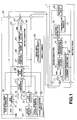
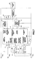
- Fig.1 shows an illustrative structure of a system made up of a battery pack 1 and a video tape recorder with a built-in camera, referred to hereinafter in their entirety as a video camera 60, as an example of an electronic equipment carrying the battery pack 1 and having the function of displaying the residual battery capacity.
- the video camera 60 has loaded thereon the battery pack 1 outputting at least the information on the residual battery capacity, the charging/discharging current detection information and the battery cell voltage detection information, and includes a computer 63 having a communication circuit 65, a calculation circuit 66 and a display control circuit 67, and a display device 64 supplied with the result of calculations of the calculation circuit 66 for displaying the residual battery quantity from the displayed signal.
- the communication circuit 65 is arranged to receive the information of various sorts from the battery pack 1, while the calculation circuit 66 calculates the current residual battery capacity based on the various sorts of the information from the battery pack 1 received by the communication circuit 65.
- the display control circuit 67 generates the display signals based on the results of calculations by the calculation circuit 66.
- the video camera 60 has various sorts of arrangements for imaging and for recording/reproducing imaged video signals. However, in the illustration of Fig.1, only the micro-computer 63 and the display device 64, as main components of the present invention, are shown.
- the battery pack 1 includes at least the above-mentioned micro-computer 10, a battery cell 20, a charging/discharging current detection circuit 80 for detecting the charging/discharging current, a voltage detection circuit 18 for detecting the voltage across the terminals of the battery cell 20 and a temperature sensor 19 for detecting the temperature of the battery cell 20.
- a communication circuit 72 for having communication with the video camera 60 and an information generating circuit 71 for generating the information specifying the state of the battery pack 1.
- the information generating circuit 71 illustrated generates, as the information specifying the state of the battery pack 1, the temperature detection information along with the information specifying the residual battery capacity, charging/discharging current detection information and the battery cell detection information.
- the information from the information generating circuit 71 such as that specifying the residual battery capacity, is sent via the communication circuit 72 to the video camera 60.
- the detailed structure of the battery pack 1 will be explained subsequently.
- the battery pack 1 has its positive terminal connected to the positive terminal of the video camera 60, while having its negative terminal connected to the negative terminal of the video camera 60.
- the power is supplied via these positive and negative terminals to the video camera 60 from the battery pack 1.
- the communication of the information between the battery pack 1 and the video camera 60 is via a control terminal C.
- the communication between the micro-computer 10 of the battery pack 1 and the vide camera 60 via control terminal C occurs via buffer amplifiers 11, 12 and via buffer amplifiers 61, 62 on the side of the battery pack 1 and on the side of the video camera 60, respectively.
- the video camera 60 receives the information showing the status of the battery pack 1, sent via the control terminal from the battery pack 1, and seizes the received information in the micro-computer 63.
- the information showing the status of the battery pack is the information specifying the status of the battery pack 1.
- the information received via the communication circuit 65 of the micro-computer 63 is sent to the calculation circuit 66 where various calculations are executed for finding the residual usable time of the video camera 60, in other words, the usable residual service life of the battery, from the received information, such as the information specifying the residual battery capacity.
- the residual usable time of the video camera 60 may be exemplified by the residual recording time of recording imaged picture signals on a recording medium, such as a magnetic tape, and the residual playback time in reproducing the imaged picture signals, that is the possible operating time of the video camera 60.
- the display control circuit 67 generates, based on the residual usable time of the battery as found by the calculation circuit 66, the residual battery service time display signal for display on so-called on-screen display (OSD) or on display means of the display device 64 of the main body portion of the video camera 60.
- OSD on-screen display
- the display device 64 has, as the above-mentioned display means, a viewfinder (EVF) 102 and a liquid crystal panel 101, and displays the information derived from the residual battery time display signal supplied to the display screen of these display means from the display control circuit 67.
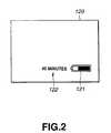
- Fig.2 shows an illustrative example of the residual battery time displayed on the display means. Specifically, Fig.2 shows a display example comprised of a digital time display 122 specifying the residual battery time and a level display 121 for intuitive visual indication of the ratio in percentage of the current residual battery time to the fully charged state of the battery, with the display 122 and the display 121 being on a display screen 120 of the display means.
- the digital time display 122 specifies the residual battery time by numerical indication which herein is 40 minutes.
- the level display 121 may be designed for displaying the level in four or more steps or steplessly for specifying the residual battery time. The detailed structure and operation of the display device 64 will be explained subsequently.
- the system of the instant embodiment to apprize the user of the video camera 60 of the residual usable battery time, that is the possible operating time of the video camera 60, by displaying the residual battery time on the display screen of the display device 64 of the video camera 60.
- the residual battery capacity display technique by the level display 121 is used for enabling intuitive and readily comprehensible display, while the residual battery capacity display technique by the time display 122 in minutes is used for improving accuracy in the residual battery quantity display. This enables the user of the video camera 60 to supervise the imaging time or playback time easily.
- the integrated value of the discharge current is roughly proportionate to time, as shown n the graph of Fig.3. If the minimum usable voltage of the video camera 60 (terminal battery voltage or battery termination voltage) is fixed, the point of terminal battery voltage is positioned between start of discharge and complete discharge, that is absence of energy in the battery cell 20.
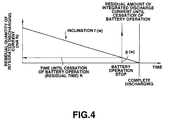
- the relation to the discharge time of the residual amount of the integrated discharge current until complete discharge is as shown in Fig.4. If, in the graph of Fig.4, the battery terminal point is taken as an origin and a coordinate system is set, the ordinate represents the residual amount of the integrated discharge current up to the battery termination and the abscissa represents the residual time up to the battery termination. Thus, if the residual amount of the integrated discharge current up to battery termination is known, it becomes possible to uniquely find the residual battery time.
- the discharge current becomes high.
- the discharge characteristics are as shown in Fig.5. From the graph of Fig.5, it is seen that the rate of the residual time to the residual amount of the integrated discharge current becomes smaller than if the power consumption is low as in Fig.4. The residual amount of the integrated discharge current since battery termination until complete discharge is changed with the effect of internal impedance of the battery cell 20 if the power consumption is high.
- R, Qd, W, f(W), Q and g(W) denote time until battery termination (residual time), an integrated discharge current up to battery termination, power consumption of the video camera 60, a power-dependent coefficient and a power-dependent residual amount of the integrated discharge current on battery termination.
- f(W) is a power-dependent coefficient for converting the residual amount of the integrated discharge current into residual time
- g(W) is the power-dependent residual amount of the integrated discharge current as from battery termination up to complete discharge.
- Equation (1) becomes an equation (2):
- T denotes the battery cell temperature
- h1(T) and h2(T) denote the temperature-dependent coefficients of the battery cell.
- Q, h1(T) and h2(T) are proper to the battery pack 1, while f(W) and g(W)are proper to the video camera 60.
- Equation (2) is obtained by multiplying f(W) and h(W) in the equation (1) with the temperature-dependent coefficients h1(T) and h2(T), respectively.
- the temperature-dependent coefficients h1(T) and h2(T) assume different values depending on the sorts of the battery cell. Thus it becomes possible to absorb the difference in the equation ascribable to the difference in the battery cell.
- the power consumption (W) differs with different using states of the video camera 60.
- the time R1 until battery termination for the power consumption W1 and the time R2 until battery termination for the power consumption W2, where W2 ⁇ W1 are represented by the equations (3) to (6):
- R1 (Q - g(W1)) f(W1)
- R2 (Q - g(W2)) f(W2)
- R1 (Q - g(W1)) h2(T)) f(W1) h1(T)
- R2 (Q - g(W2) h2(T)) f(W2) h1(T)
- the equations (3) and (4) correspond to the equation (1)
- the equations (5) and (6) correspond to the equation (2).
- the residual battery quantity is calculated in the present system responsive to the changes in the power consumption, so that, even if the power consumption W of the video camera 60 is changed, it becomes possible to display the residual battery time corresponding to the changes in the using state of the video camera 60.
- the residual battery time is calculated using only the power consumption, without regard to the sort (contents) of the using states of the video camera 60, while no particular parameter specifying the using state of the video camera 60 is required for calculating the residual battery time.
- the above-described method for calculating the residual battery time represents a method of high universality independent of the sort of the video camera 60.
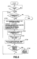
- step ST31 in Fig.6 it is checked whether or not the power source has been turned on. If the power source is not turned on, the check of step ST31 is repeated. If the power source has been turned off, processing transfers to step ST32.
- step ST32 it is checked whether or not communication can be had with the battery pack 1. If the result of check is NO, processing is terminated. If the result of check is YES, processing transfers to step ST33.
- the current I, voltage V, residual amount of integrated discharge current Q, and the temperature-dependent coefficients h1(T), h2(T), as data required for calculating the residual quantity, are received from the battery pack 1.
- the power consumption W is calculated.
- f(W) and g(W) are calculated.
- the residual time until battery termination R is calculated, using the equations (2), (5) and (6) or using the equations (1), (3) and (4) if temperature changes are not taken into account.
- step ST36 it is checked whether or not the residual quantity can be displayed. If the residual quantity cannot be displayed, processing reverts to step ST32 and, if the residual quantity can be displayed, the residual quantity (residual battery time) is displayed at step ST38 on the display device 64.
- the residual quantity displayed may be the usable time of the battery pack 1 (usable time for the video camera 60) or the residual capacity of the battery pack 1, such as the residual capacity up to the above-described battery terminal point.
- the algorithm for calculating the residual amount is independent of the battery cell to enable the algorithm to be unified. Since the residual battery capacity is displayed in unit of time, it becomes possible for the user to supervise the imaging time. By displaying the residual battery time not only by the four-level display 121, but also by the minute-based time display 122, the residual battery quantity can be displayed with improved accuracy.
- Fig.7 shows an illustrative structure of the battery pack 1.
- the battery cell 20 has its positive terminal connected to the positive terminal TM+ of the battery pack 1, while having its negative electrode connected via a current detection resistor R7 to the negative terminal TM- of the battery pack 1.
- the micro-computer 10 enclosed in the battery pack 1 is fed with the current from a micro-computer power source 16, inclusive of a serial regulator or a resetting circuit, so as to be operated by the current supplied from the micro-computer power source 16.
- the micro-computer 10 has its charging current detection input terminal D11 connected to an output terminal of an operational amplifier 13 provided for detecting the charging current, while having its discharging current detection input terminal D12 connected to an output terminal of the operational amplifier 14 provided for detecting the discharging current.
- the micro-computer 10 has its interrupt input terminal connected to an output terminal of a two-input AND gate 15, two input terminals of which are connected to output terminals of the operational amplifiers 13 and 14.
- the two-input AND gate 15 has its output terminal connected via a pull-up resistor R8 to a power source terminal.
- the micro-computer 10 has its temperature detection input terminal connected to an output terminal of a temperature sensor 19 detecting the ambient temperature of the battery cell 20, while having its voltage detection input terminal connected to an output terminal of a voltage detection circuit 18 configured for detecting the terminal voltage of the battery cell 20.
- the micro-computer 10 also has its cycle data input terminal connected to an output terminal of a non-volatile memory 17 as later explained, while having its grounding terminal to a negative electrode of the battery cell 20.
- the micro-computer 10 has its input terminal or SIN terminal and output terminal or SOUT terminal for having communication with the video camera 60 connected to buffer amplifiers 11, 12, respectively.
- the terminals fed with analog inputs such as the above-mentioned charging current detection input terminal D11, discharging current detection input terminal D12, temperature detection input terminal or the voltage detection input terminal, are all A/D input ports, there is enclosed in the micro-computer 10 an A/D converter for converting the analog inputs to digital signals.
- the voltage detection circuit 18 is a voltage-dividing resistor circuit made up of resistors R9 and R10 for detecting the voltage across the terminals of the-battery cell 20.
- the detected voltage value from the voltage detection circuit 18 is supplied to the voltage detection input terminal of the micro-computer 10.
- the voltage across the terminals of the battery cell 20 can be known by the micro-computer 10 based on the detected voltage value from the voltage detection circuit 18 supplied to its voltage detection input terminal.
- the temperature sensor 19 is comprised of, for example, a temperature detecting thermistor and arranged in proximity to or in contact with the battery cell 20.
- the detected temperature of the temperature sensor 19 is supplied to the temperature detection input terminal of the micro-computer 10.
- the micro-computer 10 can grasp the temperature of the detected temperature supplied to the temperature detection input terminal.
- the operational amplifier 13 has its non-inverting input terminal connected via a resistor R3 and a current/voltage detection resistor R7 to the negative electrode of the battery cell 20, while having its inverting input terminal connected to a feedback resistor R2 for amplification factor setting and to a resistor R1.
- an output terminal of the operational amplifier 13 outputs an amplified voltage value obtained on amplifying the current flowing in the battery pack 1 (current flowing during charging) depending on the resistance ratio of the resistors R1 and R2 (R2/R1) .
- the operational amplifier 14 has its non-inverting input terminal connected to the negative electrode of the battery cell 20 via a resistor R6 and a current/voltage detecting resistor R7, while having its inverting input terminal connected to a negative feedback resistor R5 and to a resistor R4.
- an output of the operational amplifier 14 outputs an amplified voltage value obtained on amplifying the current flowing in the battery pack 1 (current flowing during discharging) depending on the resistance ratio of the resistors R4 and R5 (R5/R4).
- a transistor switch Tr1 is, for example, a field-effect transistor having its gate connected to a switching control output terminal SW1 of the micro-computer 10.
- the above-mentioned resistor R1 is connected between the drain and the source of the transistor switch Tr1.
- the transistor switch Tr1 is turned on, so that the resistance by the resistor R1 becomes substantially zero, that is, the resistance is made up only of the internal resistance of the transistor switch Tr1.
- This increases the amplification factor (gain) of the operational amplifier 13 which is set responsive to the resistance ratio of the resistors R1 and R2 (R2/R1).
- a transistor switch Tr2 is, for example, a field-effect transistor having its gate connected to a switching control output terminal SW2 of the micro-computer 10.
- the above-mentioned resistor R4 is connected between the drain and the source of the transistor switch Tr2.
- the transistor switch Tr2 when the signal level from a switching control output terminal SW2 of the micro-computer 10 goes high, the transistor switch Tr2 is turned on, so that the resistance by the resistor R4 becomes substantially zero, that is, the resistance is made up only of the internal resistance of the transistor switch Tr2. This increases the amplification factor (gain) of the operational amplifier 14. On the other hand, if the signal level of the signal from the switching control output terminal SW2 of the micro-computer 10 goes low, the transistor switch Trl is turned off, so that the amplification factor of the operational amplifier 13 becomes small.
- the micro-computer 10 During normal operational mode, that is during running, the micro-computer 10 perpetually monitors the level of the charging current detection input terminal D11 and the discharging current detection input terminal D12. If the levels of the terminals D11 and D12 become higher than a pre-set level, the micro-computer 10 sets the signals of the switching control output terminals SW1 and SW2 to a low level. This turns both the transistor switches Tr1 and Tr2 off to lower the amplification gain of the operational amplifiers 13 and 14. Thus, during the normal operational mode, that is during running, the micro-computer 10 can measure the current flowing in the battery pack 1, that is the current flowing during charging or the current flowing during discharging) using the output values of the operational amplifiers 13 and 14 having the amplification gains reduced as described above. Thus, if the current flowing during charging/discharging is known, the integrated value of the charging/discharging current can be calculated.
- the output values of the operational amplifiers 13, 14, whose amplification gains have been reduced are also reduced. That is, the signal levels of the signals from the charging current detection input terminal D11 and the discharging current detection input terminal D12 are also reduced. If the signal levels of the signals of the terminals D11 and D12 of the micro-computer 10 become lower than a pre-set level and this state persists for a pre-set time, the micro-computer 10 deems that the unloaded state persists and transfers to a power saving mode (sleep mode). During this sleep mode, the power consumption becomes smaller than during the normal operational mode, thus enabling energy saving.
- the micro-computer 10 sets the signal levels of the signals from the switching control output terminals SW1 and SW2 to a high level. This turns the transistors Tr1, Tr2 on for increasing the amplification gains of the operational amplifiers 13, 14.
- the micro-computer 10 can measure the small current flowing in the battery pack 1 (small current flowing during charging or during discharging) using the output values of the operational amplifiers 13, 14 having the increased amplification gains.
- the output values of the operational amplifiers 13, 14 with the decreased amplification gains are also increased. That is, the level of the two input terminals of the two-input NAND gate 15 goes high so that the output level of the two-input NAND gate 15 goes low. That is, if the output level of the two-input NAND gate 15, supplied to the interrupt input terminal, goes low, the micro-computer 10 releases the power saving mode to transfer to the normal operating mode.
- the power consumption is smaller during the power saving mode than during the normal operational mode, thus enabling energy saving.
- the micro-computer 10 on/off controls the transistors Tr1 and-Tr2 by the switching control outputs SW1 and SW2 for enabling the switching of the amplification gains of the operational amplifiers 13, 14, such that detection of the small current during power saving mode and measurement of the current value during the normal operational mode can be realized simultaneously by the present arrangement.
- the non-volatile memory 17 is comprised of, for example, an EEP-ROM for storing data of the maximum number of the charging/discharging cycles of the battery cell 20.
- the micro-computer 10 measures the number of the charging/discharging cycles of the battery cell 20 on the basis of data on the maximum number of times of charging/discharging cycles from the non-volatile memory 17 (cycle data) and a detection voltage from the voltage detection circuit 18.
- a flag notifying such effect is transmitted to the video camera 60.
- the video camera 60 On reception of the flag transmitted from the battery pack 1, the video camera 60 makes a display prompting the user to exchange the battery pack 1 on the display device 64.
- An example of this display is "This battery is used up so exchange it with a new one”. This can easily inform the user of the used-up state of the battery pack 1.
- the power consumption is changed with the using state of the video camera 60 under the following illustrative conditions:
- the video camera 60 of the instant embodiment includes, as the display device 64, a viewfinder 102 comprised of a small-sized CRT, and a liquid crystal panel (liquid crystal display) 101, as shown in Figs.8 to 10.
- the viewfinder 102 is similar to one provided on a usual video camera and displays an scene being imaged or an image being reproduced from the video tape.
- the liquid crystal panel 101 is provided for the purpose of displaying the scene being imaged or reproduced, basically in the same way as the viewfinder 102
- the liquid crystal 101 provided in the video camera 60 of the instant embodiment can assume the state in which the liquid display panel is housed within the main body portion of the video camera 60, as shown in Fig.8. a state in which the liquid display panel can be opened up to 90° towards front in a direction indicated by arrow 111, as shown in Fig.9 and a state in which the liquid display panel can be swung in a direction shown by arrow 110 up to 210° as shown in Fig.9.
- the state in which the liquid display panel is rotated by 180° towards the front side from the opened state shown in Fig.9 is shown in Fig.10.
- the rotation of the liquid crystal panel 101 to the state shown in Fig.10 is hereinafter referred to as the panel inversion.
- the state in which the liquid crystal panel 101 is housed within the main body portion of the video camera 60 as shown in Fig.8 is termed the closed state, while that in which the liquid crystal panel 101 has been opened in the direction-indicated by arrow 111 as shown in Fig.9 is termed the opened state.
- the video camera 60 of the instant embodiment since the liquid crystal panel 101 can be opened and closed as described above, while it can be rotated towards the front side, the scene being imaged can be seen without viewing through the viewfinder 102.
- the video camera 60 can be used in a variety of ways. Since the specified structure of the opening/closing mechanism or the rotating mechanism for the liquid crystal panel 101 is not pertinent to the present invention, detailed description therefor is not made for simplicity.
- the video camera 60 of the instant embodiment has the viewfinder 102 and the liquid crystal panel 101 as the display device 64, as described above.
- both the viewfinder 102 and the liquid crystal panel 101 may be used simultaneously, only one of the viewfinder 102 and the liquid crystal panel 101 may be used, or none of the viewfinder 102 and the liquid crystal panel 101 may be used. That is, since viewfinder 102 and the liquid crystal panel 101 may or may not be used depending on the using state, the power consumption is changed.
- the residual battery quantity is calculated depending on changes in the power consumption, as described above, even although the power consumption is changed depending on the using state of the video camera 60, it becomes possible to display the residual battery service life in meeting with changed using states of the video camera 60.
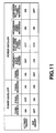
- Fig.11 shows various patterns of using states of the viewfinder 102 and the liquid crystal panel 101 in the video camera 60 of the instant embodiment. That is, the video camera 60 of the instant embodiment has a power save mode for saving the power consumption and, by turning the power save mode on or off, the use/non-use (on/off) of the viewfinder 102 and the liquid crystal panel 101 is controlled as shown in Fig.11.
- the viewfinder (EVF) 102 is turned off with the liquid crystal panel being on. If the liquid crystal panel is in the closed state, the viewfinder 102 is turned on, with the liquid crystal panel being off. In the inverted state of the liquid crystal panel 101 in which the liquid crystal panel 101 has been rotated, both the liquid crystal panel 101 and the viewfinder 102 are turned on. That is, if the power save mode is off, and the liquid crystal panel 101 is opened, only the liquid crystal panel 101 is turned on, on the assumption that the viewfinder 102 is not used by the user of the video camera 60.
- both the liquid crystal panel 101 and the viewfinder 102 are turned on, on the assumption that there is another person viewing the liquid crystal panel 101 besides the user viewing the viewfinder 102.
- the viewfinder (EVF) 102 is turned off with the liquid crystal panel 101 being on. If, in the closed state of the panel, the user is viewing through the viewfinder 102, the liquid crystal panel 101 is turned off, while the viewfinder 102 is turned on. If, in the closed state of the panel, the user is not viewing through the viewfinder 102, both the liquid crystal panel 101 and the viewfinder 102 are turned off. If, in the inverted state of the panel, the user is viewing through the viewfinder 102, both the liquid crystal panel 101 and the viewfinder 102 are turned on.
- the liquid crystal panel is in the inverted state and the user is not viewing through the viewfinder 102, only the liquid crystal panel 101 is turned on. That is, if the power save mode is on, and the panel is in the opened state, it is assumed that the viewfinder 102 is not used by the user of the video camera 60, so that only the liquid crystal panel 101 is opened for power saving. If the panel is in the closed state and the user is viewing through the viewfinder 102, the user cannot view the liquid crystal panel 101, so that only the viewfinder 102 is turned on. .
- the panel is in the closed state and the user is not viewing through the viewfinder 102, it is assumed that the user cannot view the liquid crystal panel 101, while the user is not viewing through viewfinder 102, so that both the panel and the viewfinder are turned off. If the panel is in the inverted state and the user is viewing through the viewfinder, it is assumed that there is another person is viewing the liquid crystal panel 101 besides the user viewing through the viewfinder 102, so that both the panel and the viewfinder are turned on. If the panel is in the inverted state and the user is not viewing through the viewfinder, it is assumed that the user is not viewing through the viewfinder 102 but is viewing only the liquid crystal panel 101, so that only the liquid crystal panel 101 is turned on.
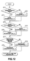
- the display control of the viewfinder 102 and the liquid crystal panel 101 depending on the patterns of the using states of the video camera 60 as described above is carried out in accordance with the flowcharts shown in Figs.12 and 13.
- the video camera 60 of the instant embodiment includes a panel opening/closure switch 79 for detecting whether the liquid crystal panel 101 is in the opened state or in the closed state, a panel inversion switch 70 for detecting whether the liquid crystal panel 101 is in the inverted state, and a viewfinder using state sensor 78 for detecting whether or not the viewfinder 102 is being seen through by the user, as shown in Fig.1.
- step ST1 it is judged at step ST1 whether the panel opening/closure switch 79 is turned on (in the opened state) or turned off (in the closed state). If it is judged at step ST1 that the panel opening/closure switch 79 is on, processing transfers to step ST2 in which the value of a panel open flag is set to "1" as the information specifying that the panel opening/closure switch 79 is on. If it is judged at step ST1 that the panel opening/closure switch 79 is off, processing transfers to step ST3 in which the value of the panel open flag is set to "0" as the information specifying that the panel opening/closure switch 79 is off.
- step ST7 it is checked whether the state of the panel reversion switch 70 is on (in the inverted state) or off (in the non-inverted state). If it is judged at step ST4 that the panel reversion switch 70 is on, processing transfers to step ST5 where the value of the panel inversion flag is set to "1" as the information specifying that the panel reversion switch 70 is on. If it is judged at step ST4 that the panel reversion switch 70 is on, processing transfers to step ST6 where the value of the panel inversion flag is set to "0" as the information specifying that the panel reversion switch 70 is off.
- step ST7 it is checked whether the viewfinder using state sensor 78 is on (in the using state) or off (in the non-using state).
- the viewfinder using state sensor 78 is an infra-red sensor provided within the viewfinder 102 and is turned on and off if the user is viewing through the viewfinder 102 and if the user is not viewing through the viewfinder 102, respectively. If it is judged at step ST7 that the viewfinder using state sensor 78 is on, processing transfers to step ST8 where the value of the viewfinder using state flag set to "1" as the information specifying that the viewfinder using state sensor 78 is on. If it is judged at step ST7 that the viewfinder using state sensor 78 is off, processing transfers to step ST9 where the value of the viewfinder using state flag set to "0" as the information specifying that the is viewfinder using state sensor 78 off.
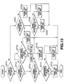
- the panel-EVF controller 68 provided within the micro-computer 63 of the video camera 60 shown in Fig.1.
- the panel-EVF controller 68 controls various parts, based on the above flags, as shown in the flowchart of Fig.13.
- step ST11 it is first checked at step ST11 whether the power save mode is set to the on-mode or to the off-mode.
- the power save mode is set to the on-mode or to the off-mode by selection from the operating menu items by a mode input unit 69 as soft keys of the video camera 60.
- a flag power save flag
- step ST21 to which processing transfers when the power save flag is "0",that is when the power save mode is off, it is checked whether the value of the panel opening flag is "1" or "0". If it is found at step ST21 that the value of the panel opening flag is "0”, processing transfers to step ST24, where the liquid crystal panel 102 is turned off, while the viewfinder (EVF) 101 is turned on, as shown in Fig.11. If it is found at step ST21 that the value of the panel opening flag is "1", processing transfers to step ST22.
- step ST22 it is checked whether the value of the panel inversion flag is "1" or "0". If it is found at step ST22 that the value of the panel inversion flag is "0”, processing transfers to step ST25 where the liquid crystal panel 102 is turned on, while the viewfinder 101 is turned off, as shown in Fig.11. If it is found at step ST22 that the value of the panel inversion flag is "1”, processing transfers to step ST23 where both the liquid crystal panel 102 and the viewfinder 101 are turned on, as shown in Fig.11.
- step ST12 to which processing transfers when the power save flag is found to be "1" at step ST11, that is when the power save mode is on, it is checked whether the value of the panel opening flag is "1" or "0". If it is found at step ST12 that the value of the panel opening flag is "0", processing transfers to step ST16 and, if otherwise, to step ST13.
- processing transfers when the value of the panel opening flag is "0", it is checked whether the value of the viewfinder using state flag is "1" or "0". If it is found at step ST16 that the value of the viewfinder using state flag is "0”, processing transfers to step ST18 where both the liquid crystal panel 102 and the viewfinder 101 are turned off. If it is found at step ST16 that the value of the viewfinder using state flag is "1”, processing transfers to step ST17 where the liquid crystal panel 102 is turned off while the viewfinder 101 is turned on.
- step ST12 to which processing transfers when the value of the panel opening flag is "1"
- step ST13 it is checked whether the value of the panel opening flag is "1" or "0". If it is judged at step ST13 that the value of the panel inversion flag is "0”, processing transfers to step ST19 where the liquid crystal panel 102 is turned on while the viewfinder 101 is turned off, as shown in Fig.11. If it is judged at step ST13 that the value of the panel inversion flag is "1", processing transfers to step ST14.
- step ST14 it is checked whether the value of the viewfinder state flag is "1" or "0". If it is found at step ST14 that the value of the viewfinder state flag is "0”, processing transfers to step ST20 where the liquid crystal panel 102 is turned on while the viewfinder 101 is turned off, as shown in Fig.ll. If it is found at step STl4 that the value of the viewfinder state flag is "1”, processing transfers to step ST15 where both the liquid crystal panel 102 and the viewfinder 101 are turned on, as shown in Fig.11.
- the video camera 60 includes an EVF driving circuit 73 for driving the viewfinder 102 based on the display signal from the display control circuit 67, an LCD driving circuit 74 for driving the liquid crystal panel 101 based on the display signal from the display control circuit 67 and a DC/DC converter 77 connected to the positive and negative terminals as described above for supplying power to the EVF driving circuit 73 and to the LCD driving circuit 74.
- the video camera 60 also includes, as a configuration for on/off control of the viewfinder 102 and the liquid crystal panel 101, a changeover switch 75 provided between the DC/DC converter 77 and the EVF driving circuit 73, a changeover switch 76 provided between the DC/DC converter 77 and the LCD driving circuit 74 and the above-mentioned panel-EVF controller 68 configured for performing on/off control of the changeover switches 75, 76 in accordance with Fig.11 and the flowcharts of Figs.12 and 13.
- the panel-EVF controller 68 performs on/off control of the changeover switches 75, 76 as shown in Figs.11 to 13 for realization of the on/off control of the liquid crystal panel 101 and the viewfinder 102.
- the electronic equipment of the present invention is not limited to the video camera but may also be a portable telephone, personal computer or the like electronic equipment having a display device capable of displaying the residual battery time.
Abstract
Description
- This invention relates to electronic equipment and methods with residual battery quantity display functions, for displaying the usable residual time of a battery pack used as a power source for the electronic equipment, such as a video camera, portable telephone or a personal computer.
- A battery pack constituted by a secondary cell, such as a lithium ion cell, NiCd cell or a nickel hydrogen cell, is well-known.
- In this known type of battery pack, a micro-computer may be provided for calculating the battery residual quantity for communication with an electronic equipment having the battery as the power source, as well as a peripheral circuit for the micro-computer and a battery cell status detection circuit required for the micro-computer to execute the calculations of the battery residual quantity.
- On a variety of electronic equipment loaded with such battery packs, a display device is sometimes mounted for displaying the residual battery capacity. In electronic equipment having this sort of display device, the residual battery capacity may be calculated and displayed on the basis of the terminal voltage of the battery power source (terminal voltage of the battery pack).
- However, with such a method for calculating the residual battery capacity from the terminal voltage of the battery power source, the following problems arise.
- First, if the discharging properties, that is the battery terminal voltage to the discharging voltage characteristics, differ with the types of battery cell, it is necessary to utilise an equation for conversion from the terminal voltage to the residual battery capacity from one battery cell to another, such that it is difficult to cope with future versions of the battery cell.
- Second, the residual battery capacity after all specifies the ratio according to the percentage of the residual capacity to the capacity of the fully charged battery, while the remaining usable time of the battery cannot be known from it.
- Third, in the current state of the art, the residual battery capacity can be derived from the discharge characteristics only approximately by gross levels, such as in four stages.
- Respective aspects of the invention are set out in
claims - A preferred embodiment of the present invention provides electronic equipment having the function of displaying the battery residual quantity, and a method for displaying the battery residual quantity, whereby it is possible to accommodate different types of battery cell, or even future versions of the battery cell, while it is also possible to know the usable residual service life of the battery with high display accuracy.
- With the electronic equipment having the function of displaying the residual battery capacity and the method for displaying the residual battery capacity embodying the present invention, the information on the residual battery capacity, charging/discharging current detection information and the battery cell voltage detection information from the battery pack are received, the current residual battery capacity is calculated based on the received information, and the residual battery capacity is displayed based on the results of calculations.
- That is, according to the preferred embodiment of the present invention, the information on the residual battery capacity, charging/discharging current detection information and the battery cell voltage detection information are sent from the battery pack to the electronic equipment, which then calculates the residual battery capacity from the received information for display. Thus it becomes possible to accommodate different types of battery cell or future versions of the battery cell, while it is also possible to know the usable residual service life of the battery with high display accuracy.
- The invention will now be described by way of example with reference to the accompanying drawings, throughout which like parts are referred to by like references, and in which:
- Fig.1 is a block circuit diagram showing an illustrative structure of an electronic equipment having the function of displaying the battery residual quantity and a system for implementing the method for displaying the battery residual quantity according to an embodiment of the present invention;
- Fig.2 illustrates an example of the residual service life of the battery as displayed on a display screen;
- Fig.3 is a graph showing the relation between the amount of integrated discharge current of the battery and time;
- Fig.4 is a graph showing the relation between the residual amount of the integrated discharge current of the battery and time;
- Fig.5 is a graph showing the relation between the residual amount of the integrated discharge current of the battery for high power consumption and time;
- Fig.6 is a flowchart showing the algorithm of calculation of the residual capacity;
- Fig.7 is a circuit diagram showing an illustrative structure of a battery pack;
- Fig.8 is a perspective view showing a video camera with a liquid crystal panel in the closed state;
- Fig.9 is a perspective view showing the video camera with the liquid crystal panel in the opened state;
- Fig.10 is a perspective view of a video camera with the liquid crystal display panel in the inverted position;
- Fig.11 illustrates on/off control of the liquid crystal display panel and a viewfinder;
- Fig.12 is a flowchart for generating flags; and
- Fig.13 is a flowchart for performing on/off control of the liquid crystal display panel and the viewfinder.
- Fig.1 shows an illustrative structure of a system made up of a
battery pack 1 and a video tape recorder with a built-in camera, referred to hereinafter in their entirety as avideo camera 60, as an example of an electronic equipment carrying thebattery pack 1 and having the function of displaying the residual battery capacity. - Referring to Fig.1, the
video camera 60 has loaded thereon thebattery pack 1 outputting at least the information on the residual battery capacity, the charging/discharging current detection information and the battery cell voltage detection information, and includes acomputer 63 having acommunication circuit 65, acalculation circuit 66 and adisplay control circuit 67, and adisplay device 64 supplied with the result of calculations of thecalculation circuit 66 for displaying the residual battery quantity from the displayed signal. Thecommunication circuit 65 is arranged to receive the information of various sorts from thebattery pack 1, while thecalculation circuit 66 calculates the current residual battery capacity based on the various sorts of the information from thebattery pack 1 received by thecommunication circuit 65. Thedisplay control circuit 67 generates the display signals based on the results of calculations by thecalculation circuit 66. Meanwhile, thevideo camera 60 has various sorts of arrangements for imaging and for recording/reproducing imaged video signals. However, in the illustration of Fig.1, only the micro-computer 63 and thedisplay device 64, as main components of the present invention, are shown. - The
battery pack 1 includes at least the above-mentioned micro-computer 10, abattery cell 20, a charging/dischargingcurrent detection circuit 80 for detecting the charging/discharging current, avoltage detection circuit 18 for detecting the voltage across the terminals of thebattery cell 20 and atemperature sensor 19 for detecting the temperature of thebattery cell 20. In the micro-computer 10 are enclosed acommunication circuit 72 for having communication with thevideo camera 60 and aninformation generating circuit 71 for generating the information specifying the state of thebattery pack 1. Theinformation generating circuit 71 illustrated generates, as the information specifying the state of thebattery pack 1, the temperature detection information along with the information specifying the residual battery capacity, charging/discharging current detection information and the battery cell detection information. The information from theinformation generating circuit 71, such as that specifying the residual battery capacity, is sent via thecommunication circuit 72 to thevideo camera 60. The detailed structure of thebattery pack 1 will be explained subsequently. - The
battery pack 1 has its positive terminal connected to the positive terminal of thevideo camera 60, while having its negative terminal connected to the negative terminal of thevideo camera 60. The power is supplied via these positive and negative terminals to thevideo camera 60 from thebattery pack 1. The communication of the information between thebattery pack 1 and thevideo camera 60 is via a control terminal C. The communication between the micro-computer 10 of thebattery pack 1 and thevide camera 60 via control terminal C occurs viabuffer amplifiers buffer amplifiers battery pack 1 and on the side of thevideo camera 60, respectively. - The
video camera 60 receives the information showing the status of thebattery pack 1, sent via the control terminal from thebattery pack 1, and seizes the received information in the micro-computer 63. The information showing the status of the battery pack is the information specifying the status of thebattery pack 1. - The information received via the
communication circuit 65 of the micro-computer 63 is sent to thecalculation circuit 66 where various calculations are executed for finding the residual usable time of thevideo camera 60, in other words, the usable residual service life of the battery, from the received information, such as the information specifying the residual battery capacity. The residual usable time of thevideo camera 60 may be exemplified by the residual recording time of recording imaged picture signals on a recording medium, such as a magnetic tape, and the residual playback time in reproducing the imaged picture signals, that is the possible operating time of thevideo camera 60. - The
display control circuit 67 generates, based on the residual usable time of the battery as found by thecalculation circuit 66, the residual battery service time display signal for display on so-called on-screen display (OSD) or on display means of thedisplay device 64 of the main body portion of thevideo camera 60. - The
display device 64 has, as the above-mentioned display means, a viewfinder (EVF) 102 and aliquid crystal panel 101, and displays the information derived from the residual battery time display signal supplied to the display screen of these display means from thedisplay control circuit 67. Fig.2 shows an illustrative example of the residual battery time displayed on the display means. Specifically, Fig.2 shows a display example comprised of adigital time display 122 specifying the residual battery time and alevel display 121 for intuitive visual indication of the ratio in percentage of the current residual battery time to the fully charged state of the battery, with thedisplay 122 and thedisplay 121 being on adisplay screen 120 of the display means. Thedigital time display 122 specifies the residual battery time by numerical indication which herein is 40 minutes. Thelevel display 121 may be designed for displaying the level in four or more steps or steplessly for specifying the residual battery time. The detailed structure and operation of thedisplay device 64 will be explained subsequently. - Thus it is possible with the system of the instant embodiment to apprize the user of the
video camera 60 of the residual usable battery time, that is the possible operating time of thevideo camera 60, by displaying the residual battery time on the display screen of thedisplay device 64 of thevideo camera 60. Also, in the instant embodiment, the residual battery capacity display technique by thelevel display 121 is used for enabling intuitive and readily comprehensible display, while the residual battery capacity display technique by thetime display 122 in minutes is used for improving accuracy in the residual battery quantity display. This enables the user of thevideo camera 60 to supervise the imaging time or playback time easily. - In the present system, the above-mentioned residual battery time is calculated based on the battery properties as now explained.
- If the battery is discharged at a constant power consumption, the integrated value of the discharge current is roughly proportionate to time, as shown n the graph of Fig.3. If the minimum usable voltage of the video camera 60 (terminal battery voltage or battery termination voltage) is fixed, the point of terminal battery voltage is positioned between start of discharge and complete discharge, that is absence of energy in the
battery cell 20. - The relation to the discharge time of the residual amount of the integrated discharge current until complete discharge is as shown in Fig.4. If, in the graph of Fig.4, the battery terminal point is taken as an origin and a coordinate system is set, the ordinate represents the residual amount of the integrated discharge current up to the battery termination and the abscissa represents the residual time up to the battery termination. Thus, if the residual amount of the integrated discharge current up to battery termination is known, it becomes possible to uniquely find the residual battery time.
- If the power consumption of the
video camera 60 is high, the discharge current becomes high. In this case, the discharge characteristics are as shown in Fig.5. From the graph of Fig.5, it is seen that the rate of the residual time to the residual amount of the integrated discharge current becomes smaller than if the power consumption is low as in Fig.4. The residual amount of the integrated discharge current since battery termination until complete discharge is changed with the effect of internal impedance of thebattery cell 20 if the power consumption is high. - This can be mathematically expressed by the following equation (1):

video camera 60, a power-dependent coefficient and a power-dependent residual amount of the integrated discharge current on battery termination. - In the equation (1), f(W) is a power-dependent coefficient for converting the residual amount of the integrated discharge current into residual time, while g(W) is the power-dependent residual amount of the integrated discharge current as from battery termination up to complete discharge.
- If account is taken of temperature changes of the
battery cell 20, the equation (1) becomes an equation (2):
battery pack 1, while f(W) and g(W)are proper to thevideo camera 60. - It is seen from the equation (2) that the equation (2) is obtained by multiplying f(W) and h(W) in the equation (1) with the temperature-dependent coefficients h1(T) and h2(T), respectively.
- The temperature-dependent coefficients h1(T) and h2(T) assume different values depending on the sorts of the battery cell. Thus it becomes possible to absorb the difference in the equation ascribable to the difference in the battery cell.
- In addition, in the above equations (1) and (2), the power consumption (W) differs with different using states of the
video camera 60. For example, the time R1 until battery termination for the power consumption W1 and the time R2 until battery termination for the power consumption W2, where W2 ≠ W1, are represented by the equations (3) to (6):


- As ma be seen from the above equations (3) to (6), the residual battery quantity is calculated in the present system responsive to the changes in the power consumption, so that, even if the power consumption W of the
video camera 60 is changed, it becomes possible to display the residual battery time corresponding to the changes in the using state of thevideo camera 60. - In other words, in the present system, the residual battery time is calculated using only the power consumption, without regard to the sort (contents) of the using states of the
video camera 60, while no particular parameter specifying the using state of thevideo camera 60 is required for calculating the residual battery time. This indicates that the above-described method for calculating the residual battery time represents a method of high universality independent of the sort of thevideo camera 60. An illustrative example in which the power consumption is changed with the using state of thevideo camera 60 will be explained subsequently. - The sequence of operations for receiving data and calculating the residual quantity in case the micro-computer 60 calculates the residual battery time based on the information from the
battery pack 1, such as the information on the residual battery capacity, is now explained using a flowchart of Fig.6. - At step ST31 in Fig.6, it is checked whether or not the power source has been turned on. If the power source is not turned on, the check of step ST31 is repeated. If the power source has been turned off, processing transfers to step ST32.
- At step ST32, it is checked whether or not communication can be had with the
battery pack 1. If the result of check is NO, processing is terminated. If the result of check is YES, processing transfers to step ST33. - At step ST33, the current I, voltage V, residual amount of integrated discharge current Q, and the temperature-dependent coefficients h1(T), h2(T), as data required for calculating the residual quantity, are received from the
battery pack 1. - At the next step ST34, the power consumption W is calculated. At step ST35, f(W) and g(W) are calculated. At step ST36, the residual time until battery termination R is calculated, using the equations (2), (5) and (6) or using the equations (1), (3) and (4) if temperature changes are not taken into account.
- Then, at step ST36, it is checked whether or not the residual quantity can be displayed. If the residual quantity cannot be displayed, processing reverts to step ST32 and, if the residual quantity can be displayed, the residual quantity (residual battery time) is displayed at step ST38 on the
display device 64. The residual quantity displayed may be the usable time of the battery pack 1 (usable time for the video camera 60) or the residual capacity of thebattery pack 1, such as the residual capacity up to the above-described battery terminal point. - With the above-described system, shown in Fig.1, in which a coefficient for compensating the difference in discharge characteristics by the
battery cell 20 of thebattery pack 1 is used for calculating the residual quantity, the algorithm for calculating the residual amount is independent of the battery cell to enable the algorithm to be unified. Since the residual battery capacity is displayed in unit of time, it becomes possible for the user to supervise the imaging time. By displaying the residual battery time not only by the four-level display 121, but also by the minute-basedtime display 122, the residual battery quantity can be displayed with improved accuracy. - Fig.7 shows an illustrative structure of the
battery pack 1. - In this figure, the
battery cell 20 has its positive terminal connected to the positive terminal TM+ of thebattery pack 1, while having its negative electrode connected via a current detection resistor R7 to the negative terminal TM- of thebattery pack 1. - The micro-computer 10 enclosed in the
battery pack 1 is fed with the current from amicro-computer power source 16, inclusive of a serial regulator or a resetting circuit, so as to be operated by the current supplied from themicro-computer power source 16. The micro-computer 10 has its charging current detection input terminal D11 connected to an output terminal of anoperational amplifier 13 provided for detecting the charging current, while having its discharging current detection input terminal D12 connected to an output terminal of theoperational amplifier 14 provided for detecting the discharging current. The micro-computer 10 has its interrupt input terminal connected to an output terminal of a two-input ANDgate 15, two input terminals of which are connected to output terminals of theoperational amplifiers gate 15 has its output terminal connected via a pull-up resistor R8 to a power source terminal. The micro-computer 10 has its temperature detection input terminal connected to an output terminal of atemperature sensor 19 detecting the ambient temperature of thebattery cell 20, while having its voltage detection input terminal connected to an output terminal of avoltage detection circuit 18 configured for detecting the terminal voltage of thebattery cell 20. The micro-computer 10 also has its cycle data input terminal connected to an output terminal of anon-volatile memory 17 as later explained, while having its grounding terminal to a negative electrode of thebattery cell 20. In addition, the micro-computer 10 has its input terminal or SIN terminal and output terminal or SOUT terminal for having communication with thevideo camera 60 connected to bufferamplifiers - The
voltage detection circuit 18 is a voltage-dividing resistor circuit made up of resistors R9 and R10 for detecting the voltage across the terminals of the-battery cell 20. The detected voltage value from thevoltage detection circuit 18 is supplied to the voltage detection input terminal of the micro-computer 10. Thus the voltage across the terminals of thebattery cell 20 can be known by the micro-computer 10 based on the detected voltage value from thevoltage detection circuit 18 supplied to its voltage detection input terminal. - The
temperature sensor 19 is comprised of, for example, a temperature detecting thermistor and arranged in proximity to or in contact with thebattery cell 20. The detected temperature of thetemperature sensor 19 is supplied to the temperature detection input terminal of the micro-computer 10. Thus the micro-computer 10 can grasp the temperature of the detected temperature supplied to the temperature detection input terminal. - The
operational amplifier 13 has its non-inverting input terminal connected via a resistor R3 and a current/voltage detection resistor R7 to the negative electrode of thebattery cell 20, while having its inverting input terminal connected to a feedback resistor R2 for amplification factor setting and to a resistor R1. Thus an output terminal of theoperational amplifier 13 outputs an amplified voltage value obtained on amplifying the current flowing in the battery pack 1 (current flowing during charging) depending on the resistance ratio of the resistors R1 and R2 (R2/R1) . On the other hand, theoperational amplifier 14 has its non-inverting input terminal connected to the negative electrode of thebattery cell 20 via a resistor R6 and a current/voltage detecting resistor R7, while having its inverting input terminal connected to a negative feedback resistor R5 and to a resistor R4. Thus an output of theoperational amplifier 14 outputs an amplified voltage value obtained on amplifying the current flowing in the battery pack 1 (current flowing during discharging) depending on the resistance ratio of the resistors R4 and R5 (R5/R4). - A transistor switch Tr1 is, for example, a field-effect transistor having its gate connected to a switching control output terminal SW1 of the micro-computer 10. The above-mentioned resistor R1 is connected between the drain and the source of the transistor switch Tr1. Thus, when the signal level from a switching control output terminal SW1 of the micro-computer 10 goes high, the transistor switch Tr1 is turned on, so that the resistance by the resistor R1 becomes substantially zero, that is, the resistance is made up only of the internal resistance of the transistor switch Tr1. This increases the amplification factor (gain) of the
operational amplifier 13 which is set responsive to the resistance ratio of the resistors R1 and R2 (R2/R1). On the other hand, if the signal level of the signal from the switching control output terminal SW1 of the micro-computer 10 goes low, the transistor switch Tr1 is turned off, so that the amplification factor of theoperational amplifier 13 is of a value in meeting with the resistance ratio of the resistors R1 and R2 (R2/R1), that is, it becomes lower than the amplification factor when the transistor switch Tr1 is turned on. Similarly, a transistor switch Tr2 is, for example, a field-effect transistor having its gate connected to a switching control output terminal SW2 of the micro-computer 10. The above-mentioned resistor R4 is connected between the drain and the source of the transistor switch Tr2. Thus, when the signal level from a switching control output terminal SW2 of the micro-computer 10 goes high, the transistor switch Tr2 is turned on, so that the resistance by the resistor R4 becomes substantially zero, that is, the resistance is made up only of the internal resistance of the transistor switch Tr2. This increases the amplification factor (gain) of theoperational amplifier 14. On the other hand, if the signal level of the signal from the switching control output terminal SW2 of the micro-computer 10 goes low, the transistor switch Trl is turned off, so that the amplification factor of theoperational amplifier 13 becomes small. - During normal operational mode, that is during running, the micro-computer 10 perpetually monitors the level of the charging current detection input terminal D11 and the discharging current detection input terminal D12. If the levels of the terminals D11 and D12 become higher than a pre-set level, the micro-computer 10 sets the signals of the switching control output terminals SW1 and SW2 to a low level. This turns both the transistor switches Tr1 and Tr2 off to lower the amplification gain of the
operational amplifiers battery pack 1, that is the current flowing during charging or the current flowing during discharging) using the output values of theoperational amplifiers - On the other hand, if, during the above normal operational mode (during running) of the micro-computer 10, the charging/discharging current flowing through the
battery pack 1 becomes smaller than the above-mentioned pre-set value, the output values of theoperational amplifiers - During this power saving mode (sleep mode), the micro-computer 10 sets the signal levels of the signals from the switching control output terminals SW1 and SW2 to a high level. This turns the transistors Tr1, Tr2 on for increasing the amplification gains of the
operational amplifiers operational amplifiers - If, during the power saving mode, the charging/discharging current value exceeds the above-mentioned pre-set value, the output values of the
operational amplifiers input NAND gate 15 goes high so that the output level of the two-input NAND gate 15 goes low. That is, if the output level of the two-input NAND gate 15, supplied to the interrupt input terminal, goes low, the micro-computer 10 releases the power saving mode to transfer to the normal operating mode. - With the arrangement of Fig.7, as described above, the power consumption is smaller during the power saving mode than during the normal operational mode, thus enabling energy saving. In addition, in the arrangement of Fig.7, the micro-computer 10 on/off controls the transistors Tr1 and-Tr2 by the switching control outputs SW1 and SW2 for enabling the switching of the amplification gains of the
operational amplifiers - The
non-volatile memory 17 is comprised of, for example, an EEP-ROM for storing data of the maximum number of the charging/discharging cycles of thebattery cell 20. The micro-computer 10 measures the number of the charging/discharging cycles of thebattery cell 20 on the basis of data on the maximum number of times of charging/discharging cycles from the non-volatile memory 17 (cycle data) and a detection voltage from thevoltage detection circuit 18. When the number of the charging/discharging cycles of thebattery cell 20 has reached the above-mentioned maximum number of times of the charging/discharging cycles, a flag notifying such effect is transmitted to thevideo camera 60. - On reception of the flag transmitted from the
battery pack 1, thevideo camera 60 makes a display prompting the user to exchange thebattery pack 1 on thedisplay device 64. An example of this display is "This battery is used up so exchange it with a new one". This can easily inform the user of the used-up state of thebattery pack 1. - The power consumption is changed with the using state of the
video camera 60 under the following illustrative conditions: - The
video camera 60 of the instant embodiment includes, as thedisplay device 64, aviewfinder 102 comprised of a small-sized CRT, and a liquid crystal panel (liquid crystal display) 101, as shown in Figs.8 to 10. Theviewfinder 102 is similar to one provided on a usual video camera and displays an scene being imaged or an image being reproduced from the video tape. Theliquid crystal panel 101 is provided for the purpose of displaying the scene being imaged or reproduced, basically in the same way as theviewfinder 102 - The
liquid crystal 101 provided in thevideo camera 60 of the instant embodiment can assume the state in which the liquid display panel is housed within the main body portion of thevideo camera 60, as shown in Fig.8. a state in which the liquid display panel can be opened up to 90° towards front in a direction indicated byarrow 111, as shown in Fig.9 and a state in which the liquid display panel can be swung in a direction shown byarrow 110 up to 210° as shown in Fig.9. The state in which the liquid display panel is rotated by 180° towards the front side from the opened state shown in Fig.9 is shown in Fig.10. The rotation of theliquid crystal panel 101 to the state shown in Fig.10 is hereinafter referred to as the panel inversion. The state in which theliquid crystal panel 101 is housed within the main body portion of thevideo camera 60 as shown in Fig.8 is termed the closed state, while that in which theliquid crystal panel 101 has been opened in the direction-indicated byarrow 111 as shown in Fig.9 is termed the opened state. With thevideo camera 60 of the instant embodiment, since theliquid crystal panel 101 can be opened and closed as described above, while it can be rotated towards the front side, the scene being imaged can be seen without viewing through theviewfinder 102. In addition, thevideo camera 60 can be used in a variety of ways. Since the specified structure of the opening/closing mechanism or the rotating mechanism for theliquid crystal panel 101 is not pertinent to the present invention, detailed description therefor is not made for simplicity. - The
video camera 60 of the instant embodiment has theviewfinder 102 and theliquid crystal panel 101 as thedisplay device 64, as described above. Depending on the using state of thevideo camera 60, both theviewfinder 102 and theliquid crystal panel 101 may be used simultaneously, only one of theviewfinder 102 and theliquid crystal panel 101 may be used, or none of theviewfinder 102 and theliquid crystal panel 101 may be used. That is, sinceviewfinder 102 and theliquid crystal panel 101 may or may not be used depending on the using state, the power consumption is changed. - With the system of the instant embodiment, since the residual battery quantity is calculated depending on changes in the power consumption, as described above, even although the power consumption is changed depending on the using state of the
video camera 60, it becomes possible to display the residual battery service life in meeting with changed using states of thevideo camera 60. - Fig.11 shows various patterns of using states of the
viewfinder 102 and theliquid crystal panel 101 in thevideo camera 60 of the instant embodiment. That is, thevideo camera 60 of the instant embodiment has a power save mode for saving the power consumption and, by turning the power save mode on or off, the use/non-use (on/off) of theviewfinder 102 and theliquid crystal panel 101 is controlled as shown in Fig.11. - If, in this figure, the power save mode is off, and the
liquid crystal panel 101 is opened, the viewfinder (EVF) 102 is turned off with the liquid crystal panel being on. If the liquid crystal panel is in the closed state, theviewfinder 102 is turned on, with the liquid crystal panel being off. In the inverted state of theliquid crystal panel 101 in which theliquid crystal panel 101 has been rotated, both theliquid crystal panel 101 and theviewfinder 102 are turned on. That is, if the power save mode is off, and theliquid crystal panel 101 is opened, only theliquid crystal panel 101 is turned on, on the assumption that theviewfinder 102 is not used by the user of thevideo camera 60. On the other hand, if the panel is closed, the user cannot view the liquid crystal panel, so that only theviewfinder 102 is turned on. In the inverted stated of theliquid crystal panel 101, both theliquid crystal panel 101 and theviewfinder 102 are turned on, on the assumption that there is another person viewing theliquid crystal panel 101 besides the user viewing theviewfinder 102. - If, in Fig.11, the power save mode is on, and the
liquid crystal panel 101 is opened, the viewfinder (EVF) 102 is turned off with theliquid crystal panel 101 being on. If, in the closed state of the panel, the user is viewing through theviewfinder 102, theliquid crystal panel 101 is turned off, while theviewfinder 102 is turned on. If, in the closed state of the panel, the user is not viewing through theviewfinder 102, both theliquid crystal panel 101 and theviewfinder 102 are turned off. If, in the inverted state of the panel, the user is viewing through theviewfinder 102, both theliquid crystal panel 101 and theviewfinder 102 are turned on. On the other hand, if the liquid crystal panel is in the inverted state and the user is not viewing through theviewfinder 102, only theliquid crystal panel 101 is turned on. That is, if the power save mode is on, and the panel is in the opened state, it is assumed that theviewfinder 102 is not used by the user of thevideo camera 60, so that only theliquid crystal panel 101 is opened for power saving. If the panel is in the closed state and the user is viewing through theviewfinder 102, the user cannot view theliquid crystal panel 101, so that only theviewfinder 102 is turned on. . If the panel is in the closed state and the user is not viewing through theviewfinder 102, it is assumed that the user cannot view theliquid crystal panel 101, while the user is not viewing throughviewfinder 102, so that both the panel and the viewfinder are turned off. If the panel is in the inverted state and the user is viewing through the viewfinder, it is assumed that there is another person is viewing theliquid crystal panel 101 besides the user viewing through theviewfinder 102, so that both the panel and the viewfinder are turned on. If the panel is in the inverted state and the user is not viewing through the viewfinder, it is assumed that the user is not viewing through theviewfinder 102 but is viewing only theliquid crystal panel 101, so that only theliquid crystal panel 101 is turned on. - The display control of the
viewfinder 102 and theliquid crystal panel 101 depending on the patterns of the using states of thevideo camera 60 as described above is carried out in accordance with the flowcharts shown in Figs.12 and 13. - It is noted that the
video camera 60 of the instant embodiment includes a panel opening/closure switch 79 for detecting whether theliquid crystal panel 101 is in the opened state or in the closed state, apanel inversion switch 70 for detecting whether theliquid crystal panel 101 is in the inverted state, and a viewfinder usingstate sensor 78 for detecting whether or not theviewfinder 102 is being seen through by the user, as shown in Fig.1. - Thus, in the flowchart of Fig.12, it is judged at step ST1 whether the panel opening/
closure switch 79 is turned on (in the opened state) or turned off (in the closed state). If it is judged at step ST1 that the panel opening/closure switch 79 is on, processing transfers to step ST2 in which the value of a panel open flag is set to "1" as the information specifying that the panel opening/closure switch 79 is on. If it is judged at step ST1 that the panel opening/closure switch 79 is off, processing transfers to step ST3 in which the value of the panel open flag is set to "0" as the information specifying that the panel opening/closure switch 79 is off. - At the next step ST7, it is checked whether the state of the
panel reversion switch 70 is on (in the inverted state) or off (in the non-inverted state). If it is judged at step ST4 that thepanel reversion switch 70 is on, processing transfers to step ST5 where the value of the panel inversion flag is set to "1" as the information specifying that thepanel reversion switch 70 is on. If it is judged at step ST4 that thepanel reversion switch 70 is on, processing transfers to step ST6 where the value of the panel inversion flag is set to "0" as the information specifying that thepanel reversion switch 70 is off. - At the next step ST7, it is checked whether the viewfinder using
state sensor 78 is on (in the using state) or off (in the non-using state). The viewfinder usingstate sensor 78 is an infra-red sensor provided within theviewfinder 102 and is turned on and off if the user is viewing through theviewfinder 102 and if the user is not viewing through theviewfinder 102, respectively. If it is judged at step ST7 that the viewfinder usingstate sensor 78 is on, processing transfers to step ST8 where the value of the viewfinder using state flag set to "1" as the information specifying that the viewfinder usingstate sensor 78 is on. If it is judged at step ST7 that the viewfinder usingstate sensor 78 is off, processing transfers to step ST9 where the value of the viewfinder using state flag set to "0" as the information specifying that the is viewfinder usingstate sensor 78 off. - If the values of the panel opening flag, panel inversion flag and the viewfinder state flag are set as described above, these are sent to the panel-
EVF controller 68 provided within themicro-computer 63 of thevideo camera 60 shown in Fig.1. - The panel-
EVF controller 68 controls various parts, based on the above flags, as shown in the flowchart of Fig.13. - In the flowchart, shown in Fig.13, it is first checked at step ST11 whether the power save mode is set to the on-mode or to the off-mode. In the present system, the power save mode is set to the on-mode or to the off-mode by selection from the operating menu items by a
mode input unit 69 as soft keys of thevideo camera 60. In this manner, a flag (power save flag) is set which assumes the value of "1" or the value of "0" if the power save mode is on or off, respectively. Thus, at step ST11, it is checked whether the value of the power save flag is "1" or "0". If, at step ST11, the value of the power save flag is found to be "1", processing transfers to step ST12 and, if otherwise, processing transfers to step ST21. - At the step ST21, to which processing transfers when the power save flag is "0",that is when the power save mode is off, it is checked whether the value of the panel opening flag is "1" or "0". If it is found at step ST21 that the value of the panel opening flag is "0", processing transfers to step ST24, where the
liquid crystal panel 102 is turned off, while the viewfinder (EVF) 101 is turned on, as shown in Fig.11. If it is found at step ST21 that the value of the panel opening flag is "1", processing transfers to step ST22. - At step ST22, it is checked whether the value of the panel inversion flag is "1" or "0". If it is found at step ST22 that the value of the panel inversion flag is "0", processing transfers to step ST25 where the
liquid crystal panel 102 is turned on, while theviewfinder 101 is turned off, as shown in Fig.11. If it is found at step ST22 that the value of the panel inversion flag is "1", processing transfers to step ST23 where both theliquid crystal panel 102 and theviewfinder 101 are turned on, as shown in Fig.11. - At the step ST12, to which processing transfers when the power save flag is found to be "1" at step ST11, that is when the power save mode is on, it is checked whether the value of the panel opening flag is "1" or "0". If it is found at step ST12 that the value of the panel opening flag is "0", processing transfers to step ST16 and, if otherwise, to step ST13.
- At the step ST16, processing transfers when the value of the panel opening flag is "0", it is checked whether the value of the viewfinder using state flag is "1" or "0". If it is found at step ST16 that the value of the viewfinder using state flag is "0", processing transfers to step ST18 where both the
liquid crystal panel 102 and theviewfinder 101 are turned off. If it is found at step ST16 that the value of the viewfinder using state flag is "1", processing transfers to step ST17 where theliquid crystal panel 102 is turned off while theviewfinder 101 is turned on. - At the step ST12 to which processing transfers when the value of the panel opening flag is "1", it is checked whether the value of the panel opening flag is "1" or "0". If it is judged at step ST13 that the value of the panel inversion flag is "0", processing transfers to step ST19 where the
liquid crystal panel 102 is turned on while theviewfinder 101 is turned off, as shown in Fig.11. If it is judged at step ST13 that the value of the panel inversion flag is "1", processing transfers to step ST14. - Art step ST14, it is checked whether the value of the viewfinder state flag is "1" or "0". If it is found at step ST14 that the value of the viewfinder state flag is "0", processing transfers to step ST20 where the
liquid crystal panel 102 is turned on while theviewfinder 101 is turned off, as shown in Fig.ll. If it is found at step STl4 that the value of the viewfinder state flag is "1", processing transfers to step ST15 where both theliquid crystal panel 102 and theviewfinder 101 are turned on, as shown in Fig.11. - The on/off control of the
liquid crystal panel 102 and theviewfinder 101 as shown in Figs.11 to 13 is implemented by a arrangement as now explained. - Returning to Fig.1, the
video camera 60 includes anEVF driving circuit 73 for driving theviewfinder 102 based on the display signal from thedisplay control circuit 67, anLCD driving circuit 74 for driving theliquid crystal panel 101 based on the display signal from thedisplay control circuit 67 and a DC/DC converter 77 connected to the positive and negative terminals as described above for supplying power to theEVF driving circuit 73 and to theLCD driving circuit 74. Thevideo camera 60 also includes, as a configuration for on/off control of theviewfinder 102 and theliquid crystal panel 101, achangeover switch 75 provided between the DC/DC converter 77 and theEVF driving circuit 73, achangeover switch 76 provided between the DC/DC converter 77 and theLCD driving circuit 74 and the above-mentioned panel-EVF controller 68 configured for performing on/off control of the changeover switches 75, 76 in accordance with Fig.11 and the flowcharts of Figs.12 and 13. - That is, with the
video camera 60 of the instant embodiment, the panel-EVF controller 68 performs on/off control of the changeover switches 75, 76 as shown in Figs.11 to 13 for realization of the on/off control of theliquid crystal panel 101 and theviewfinder 102. - By performing on/off control of the
liquid crystal panel 101 and theviewfinder 102 in this manner, there is produced a change in the power consumption of thevideo camera 60. - Although the foregoing explanation has been made taking a video camera as an example of the electronic equipment on which is loaded the battery pack, the electronic equipment of the present invention is not limited to the video camera but may also be a portable telephone, personal computer or the like electronic equipment having a display device capable of displaying the residual battery time.
Claims (21)
- An electronic equipment with a residual battery quantity display function having loaded thereon a battery pack configured for outputting the residual battery capacity information, charging/discharging current detection information and the battery cell voltage detection information, comprising:communication means for receiving the above respective types of the information from the battery pack;calculation means for calculating the current residual battery quantity based on the respective items of the information from said battery pack received by said communication means; anddisplay means for displaying the residual battery quantity from said calculation means.
- The electronic equipment with a residual battery quantity display function as claimed in claim 1 wherein said battery pack outputs the information on a correction coefficient used for calculating the residual battery quantity; and wherein said calculation means calculates the residual battery quantity as corrected by said correction coefficient.
- The electronic equipment with a residual battery quantity display function as claimed in claim 2 wherein said correction coefficient information is the temperature information of the battery pack.
- The electronic equipment with a residual battery quantity display function as claimed in claim 1 wherein the residual battery capacity information of said battery pack is the information on the residual quantity of the integrated discharge current and the residual battery quantity as calculated by the calculation means is the residual battery service life.
- The electronic equipment with a residual battery quantity display function as claimed in claim 1 wherein said display means has a liquid crystal panel and/or a viewfinder.
- The electronic equipment with a residual battery quantity display function as claimed in claim 1 wherein said display means performs OSD display.
- The electronic equipment with a res-idual battery quantity display function as claimed in claim 1 wherein said display means displays a numerical figure specifying the residual battery service life as said residual battery quantity.
- The electronic equipment with a residual battery quantity display function as claimed in claim 1 wherein said display means displays a minute-based numerical figure specifying the residual battery service life as said residual battery quantity.
- A method for displaying the residual battery quantity comprising:transmitting the information on the residual battery capacity of a battery cell enclosed in a battery pack, charging/discharging current detection information an the battery cell voltage detection information from the battery pack to an electronic equipment employing the battery;finding, by calculations on the side of the electronic equipment, the current residual battery based on the residual battery capacity information, charging/discharging current detection information and the battery cell voltage detection information, thus transmitted; anddisplaying the residual battery quantity, thus calculated, on display means.
- The method for displaying the residual battery quantity as claimed in claim 9 wherein said battery pack outputs the information on correction coefficients used for calculating the residual battery quantity from the battery-pack; and wherein said electronic equipment calculates the residual battery quantity as corrected by said correction coefficients.
- The method for displaying the residual battery quantity as claimed in claim 10 wherein said correction coefficient information is the temperature information of the battery pack.
- The method for displaying the residual battery quantity as claimed in claim 9 wherein the residual battery quantity information of said battery pack is the information on the residual quantity of the integrated discharge current and the residual battery quantity as calculated by the calculation means is the residual battery service life usable for the electronic equipment.
- The method for displaying the residual battery quantity as claimed in claim 9 wherein said display is made on a liquid crystal panel or on a viewfinder.
- The method for displaying the residual battery quantity as claimed in claim 9 wherein said display is made as OSD display.
- The method for displaying the residual battery quantity as claimed in claim 9 wherein a numerical figure specifying the residual battery service life as said residual battery quantity is displayed as said residual battery quantity.
- The method for displaying the residual battery quantity as claimed in claim 9 wherein a minute-based numerical figure specifying the residual battery service life as said residual battery quantity is displayed as said residual battery quantity.
- A VCR with a built-in camera having loaded thereon a battery pack configured for outputting the residual battery capacity information, charging/discharging current detection information and the battery cell voltage detection information, comprising:communication means for receiving the above respective types of the information from the battery pack;calculation means for calculating the current residual battery quantity based on the respective items of the information from said battery pack received by said communication means; anddisplay means for displaying the residual battery quantity from said calculation means.
- The VCR with a built-in camera as claimed in claim 17 wherein the residual battery quantity information of said battery pack is the information on the residual quantity of the integrated discharge current and the residual battery quantity as calculated by the calculation means is the residual battery service life.
- The VCR with a built-in camera as claimed in claim 17 wherein the residual battery quantity as calculated by said calculating means is the residual recording time of the VCR with the built-in camera
- The VCR with a built-in camera as claimed in claim 17 wherein the residual battery quantity as calculated by said calculating means is the residual playback time of the VCR with the built-in camera.
- The VCR with a built-in camera as claimed in claim 17 wherein said display means has a liquid crystal panel and/or a viewfinder.
Applications Claiming Priority (2)
| Application Number | Priority Date | Filing Date | Title |
|---|---|---|---|
| JP51790/96 | 1996-03-08 | ||
| JP5179096 | 1996-03-08 |
Publications (3)
| Publication Number | Publication Date |
|---|---|
| EP0794438A2 true EP0794438A2 (en) | 1997-09-10 |
| EP0794438A3 EP0794438A3 (en) | 1998-06-17 |
| EP0794438B1 EP0794438B1 (en) | 2007-06-20 |
Family
ID=12896746
Family Applications (1)
| Application Number | Title | Priority Date | Filing Date |
|---|---|---|---|
| EP97301518A Expired - Lifetime EP0794438B1 (en) | 1996-03-08 | 1997-03-06 | Electronic equipment with residual battery quantity display function and method of displaying the residual battery quantity |
Country Status (6)
| Country | Link |
|---|---|
| US (1) | US6522361B2 (en) |
| EP (1) | EP0794438B1 (en) |
| JP (1) | JP4706689B2 (en) |
| CN (1) | CN1075680C (en) |
| DE (1) | DE69737821T2 (en) |
| MY (1) | MY119124A (en) |
Cited By (7)
| Publication number | Priority date | Publication date | Assignee | Title |
|---|---|---|---|---|
| EP0936719A2 (en) * | 1998-02-13 | 1999-08-18 | Sony Corporation | Battery pack and battery system |
| EP1032198A2 (en) * | 1999-02-26 | 2000-08-30 | Sony Corporation | A video camera and warning method thereof |
| GB2357585A (en) * | 1999-12-22 | 2001-06-27 | Nokia Mobile Phones Ltd | Battery life indication |
| US6915221B2 (en) | 2002-11-18 | 2005-07-05 | Telefonaktiebolaget Lm Ericsson (Publ) | Self learning system and method for predicting remaining usage time for different modes of a mobile device |
| EP1605272A1 (en) * | 2004-06-04 | 2005-12-14 | Sony Corporation | Battery remaining capacity indicating apparatus and battery remaining capacity indicating method |
| EP1626573A1 (en) * | 2003-05-19 | 2006-02-15 | Sony Corporation | Imaging device |
| WO2012019960A1 (en) * | 2010-08-13 | 2012-02-16 | Sb Limotive Company Ltd. | Method for determining a charge state of a battery |
Families Citing this family (81)
| Publication number | Priority date | Publication date | Assignee | Title |
|---|---|---|---|---|
| JP2000215919A (en) * | 1999-01-26 | 2000-08-04 | Fujitsu Ltd | Electronic apparatus and battery unit |
| SE514232C2 (en) * | 1999-01-27 | 2001-01-29 | Ericsson Telefon Ab L M | Portable multi-band communication device and a method for determining a charge consumption for the same |
| JP4200574B2 (en) * | 1999-02-10 | 2008-12-24 | 株式会社ニコン | Electronic still camera |
| JP2000253303A (en) * | 1999-02-26 | 2000-09-14 | Minolta Co Ltd | Battery driven digital camera and electronic instrument |
| JP4142205B2 (en) * | 1999-05-19 | 2008-09-03 | オリンパス株式会社 | Electronic still camera |
| JP2001246821A (en) * | 2000-03-07 | 2001-09-11 | Sony Corp | Machinery of every kind integrated with printer |
| FR2812158B1 (en) * | 2000-07-21 | 2003-06-27 | Fuji Photo Optical Co Ltd | “PROMPTER AND SIGNAL PROCESSING DEVICE USABLE IN THE PROMPTER” |
| JP4423764B2 (en) * | 2000-07-25 | 2010-03-03 | 株式会社ニコン | Electronic camera |
| EP1734421A3 (en) * | 2000-08-11 | 2007-12-19 | Seiko Epson Corporation | Electronic apparatus and method of controlling the electronic apparatus |
| CN1901251B (en) * | 2001-07-25 | 2015-06-17 | 索尼公司 | Battery device loaded on electronic device |
| JP4097183B2 (en) * | 2001-12-27 | 2008-06-11 | パナソニックEvエナジー株式会社 | Secondary battery remaining capacity estimation method and apparatus, and battery pack system |
| JP4215985B2 (en) * | 2002-02-15 | 2009-01-28 | ソニー株式会社 | Electronic device, display control method, recording medium, and program |
| JP4086539B2 (en) * | 2002-04-30 | 2008-05-14 | キヤノン株式会社 | Imaging device |
| US7508168B2 (en) * | 2002-05-16 | 2009-03-24 | Sony Corporation | Electronic apparatus with remaining battery power indicating function |
| US6996734B2 (en) * | 2002-05-22 | 2006-02-07 | Dell Products L.P. | System and method for using a legacy battery in an information handling system using a table having actual and translated remaining capacity values |
| JP2004056563A (en) * | 2002-07-22 | 2004-02-19 | Matsushita Electric Ind Co Ltd | Portable telephone set |
| JP2004184135A (en) * | 2002-11-29 | 2004-07-02 | Sanyo Electric Co Ltd | Remaining-capacity calculating system of battery |
| JP3990990B2 (en) * | 2003-01-24 | 2007-10-17 | キヤノン株式会社 | Charging device, electronic device, battery remaining amount display control method in charging device, battery remaining amount detection method in electronic device |
| JP4208586B2 (en) * | 2003-01-24 | 2009-01-14 | キヤノン株式会社 | Charging device and charging control method thereof |
| US20050062878A1 (en) * | 2003-03-26 | 2005-03-24 | Nikon Corporation | Power system and camera |
| JP4207651B2 (en) * | 2003-05-07 | 2009-01-14 | ソニー株式会社 | Charger |
| JP4269769B2 (en) * | 2003-05-07 | 2009-05-27 | ソニー株式会社 | Battery pack and electronic device |
| EP1498743A3 (en) * | 2003-07-18 | 2005-05-04 | Nikon Corporation | System for displaying residual capacity of a battery and camera |
| CA2539723A1 (en) * | 2003-09-22 | 2005-04-07 | Valence Technology, Inc. | Electrical systems, power supply apparatuses, and power supply operations methods |
| US20050088626A1 (en) * | 2003-10-28 | 2005-04-28 | Shin-Pin Huang | Projection device with battery pack |
| EP1687815B1 (en) * | 2003-11-18 | 2008-05-21 | Koninklijke Philips Electronics N.V. | Calculating required energy |
| JP4206917B2 (en) * | 2003-12-01 | 2009-01-14 | 株式会社ニコン | Batteries, cameras, camera systems and mobile devices |
| JP2005176462A (en) * | 2003-12-09 | 2005-06-30 | Canon Inc | Battery, charger, and information processing apparatus |
| US7612472B2 (en) * | 2004-01-23 | 2009-11-03 | American Power Conversion Corporation | Method and apparatus for monitoring energy storage devices |
| JP2005223762A (en) * | 2004-02-06 | 2005-08-18 | Canon Inc | Imaging apparatus and control method |
| CN100458461C (en) * | 2004-04-16 | 2009-02-04 | 美国凹凸微系有限公司 | Method for monitoring battery electricity,electronic device and circuit for said method |
| JP4123184B2 (en) * | 2004-04-27 | 2008-07-23 | ソニー株式会社 | Secondary battery remaining capacity calculation method and battery pack |
| US7518336B2 (en) * | 2004-07-22 | 2009-04-14 | Helwett-Packard Development Company, L.P. | Battery pack event-proof monitoring and analysis system and method |
| US20060168916A1 (en) * | 2004-11-05 | 2006-08-03 | Griebel Robert A E | Method and apparatus to insert stoppers into prefilled syringes |
| JP2006145809A (en) * | 2004-11-19 | 2006-06-08 | Sony Corp | Electronic equipment and its control method |
| JP3838258B2 (en) * | 2005-03-10 | 2006-10-25 | ソニー株式会社 | Battery level display method |
| CN100541904C (en) * | 2005-11-30 | 2009-09-16 | 比亚迪股份有限公司 | A kind of dump energy display circuit of secondary cell |
| KR100656588B1 (en) * | 2006-02-10 | 2006-12-13 | 삼성전자주식회사 | Potable mobile terminal capable of indicating be distinguished battery capacity by additional mounted battery and method thereof |
| JP2007227150A (en) * | 2006-02-23 | 2007-09-06 | Sony Corp | Battery device and electronic apparatus |
| US8089552B2 (en) * | 2006-04-05 | 2012-01-03 | Nikon Corporation | Camera control based on temperature sensor |
| JP5161443B2 (en) * | 2006-08-11 | 2013-03-13 | ペンタックスリコーイメージング株式会社 | camera |
| CN101135720B (en) * | 2006-08-31 | 2010-09-15 | 纬创资通股份有限公司 | System for detecting battery electric quantity and mobile phone thereof |
| JP2008076295A (en) * | 2006-09-22 | 2008-04-03 | Omron Corp | Battery life prediction system, battery life prediction method, communication terminal device, battery life prediction device, data transmission program, battery life predicting program, and computer-readable recording medium stored with program |
| JP5114911B2 (en) * | 2006-09-29 | 2013-01-09 | 富士通株式会社 | Battery pack and electronic device |
| US20080263375A1 (en) * | 2007-04-23 | 2008-10-23 | Sundstrom Robert J | Method And System For Managing Activities In A Battery Powered Device |
| US7808205B2 (en) * | 2007-05-29 | 2010-10-05 | Motorola, Inc | Battery charger and method for communicating battery pack charging status information |
| EP2162752B1 (en) * | 2007-07-09 | 2019-11-13 | Koninklijke Philips N.V. | Method and device for determining the state of charge of a battery |
| JP4829854B2 (en) * | 2007-08-30 | 2011-12-07 | キヤノン株式会社 | Electronic device and control method thereof |
| CN101982967B (en) * | 2007-11-02 | 2013-04-24 | 佳能株式会社 | Image pickup apparatus |
| KR101432590B1 (en) * | 2007-12-12 | 2014-08-21 | 엘지전자 주식회사 | Mobile terminal having menu providing function for radio charging and charging method therefor |
| JP5262213B2 (en) * | 2008-03-21 | 2013-08-14 | 富士通株式会社 | Information processing apparatus, data saving program, and data saving method |
| FR2929752B1 (en) * | 2008-04-02 | 2011-01-07 | Suez Environnement | EQUIPMENT FOR DETECTING AND TRANSMITTING MEASURED VALUES OF PHYSICAL SIZES, AND MEASURING SENSOR FOR SUCH EQUIPMENT. |
| JP5561916B2 (en) * | 2008-07-11 | 2014-07-30 | ミツミ電機株式会社 | Battery status monitoring device |
| US8305725B2 (en) * | 2009-08-21 | 2012-11-06 | Motorola Solutions, Inc. | Current limiting apparatus and method |
| US8416333B2 (en) * | 2009-08-31 | 2013-04-09 | Panasonic Corporation | Imaging apparatus |
| US8373388B2 (en) * | 2009-12-11 | 2013-02-12 | Electronics And Telecommunications Research Institute | Portable device and battery charging method thereof |
| US20110264390A1 (en) * | 2010-04-22 | 2011-10-27 | Ayman Shabra | Method and apparatus for determining state of charge values for an electrical power cell |
| KR101234234B1 (en) * | 2010-07-28 | 2013-02-18 | 삼성에스디아이 주식회사 | Vehicle using motor and controlling method of the same |
| CN101975927B (en) * | 2010-08-27 | 2012-09-05 | 华南师范大学 | Method for estimating remaining available capacity of lithium ion power battery pack |
| ES2543913T3 (en) | 2010-11-02 | 2015-08-25 | Promega Corporation | Coelenterazine derivatives and methods of use thereof |
| KR101765916B1 (en) * | 2010-12-31 | 2017-08-23 | 엘지이노텍 주식회사 | An eletronic shelf label and a managing method thereof |
| US9015513B2 (en) | 2011-11-03 | 2015-04-21 | Vocollect, Inc. | Receiving application specific individual battery adjusted battery use profile data upon loading of work application for managing remaining power of a mobile device |
| CN102508169B (en) * | 2011-11-07 | 2013-12-11 | 浙江绿源电动车有限公司 | Device and method for obtaining battery capacity |
| CN102375127B (en) * | 2011-11-11 | 2014-01-08 | 深圳市中兴移动通信有限公司 | Method for displaying residual battery electricity quantity of mobile terminal |
| JP2013115670A (en) * | 2011-11-30 | 2013-06-10 | Sony Corp | Imaging apparatus, control method thereof, and program |
| EP2811311B1 (en) | 2012-01-31 | 2018-08-29 | Osaka City University | Battery system and charge/discharge measuring apparatus |
| JP2013179729A (en) * | 2012-02-28 | 2013-09-09 | Omron Corp | Storage battery control device, storage battery control method, program, power storage system and power supply system |
| CN102749590B (en) * | 2012-07-17 | 2015-09-09 | 小米科技有限责任公司 | A kind of method and system showing battery dump energy |
| JP6128919B2 (en) * | 2013-04-01 | 2017-05-17 | キヤノン株式会社 | Display control apparatus and control method thereof |
| CN104238700A (en) * | 2013-06-06 | 2014-12-24 | 鸿富锦精密工业(深圳)有限公司 | Battery electric quantity control system and method |
| CN103941194B (en) * | 2014-04-28 | 2016-08-03 | 广西卓能新能源科技有限公司 | Intelligent lithium ion battery power quantity display method and device |
| CN104104878A (en) * | 2014-07-25 | 2014-10-15 | 深圳市中兴移动通信有限公司 | Reminding mthod and system for shooting time length in shooting process |
| CN104280685B (en) * | 2014-10-11 | 2018-06-19 | 惠州Tcl移动通信有限公司 | The computational methods and its computing system of battery capacity of mobile terminal |
| WO2018047376A1 (en) * | 2016-09-12 | 2018-03-15 | アルプス電気株式会社 | Remaining battery capacity estimation device, remaining battery capacity estimation method, and program |
| CN109216814A (en) * | 2017-06-29 | 2019-01-15 | 青岛恒金源电子科技有限公司 | A kind of base station Li-ion batteries piles and its operation method |
| CN107748328A (en) * | 2017-09-12 | 2018-03-02 | 莱克电气股份有限公司 | Digitize display system and method |
| CN107677969A (en) * | 2017-10-25 | 2018-02-09 | 福州福光电子有限公司 | The charge/discharge test device of distributed complete online batteries |
| JP6995634B2 (en) * | 2018-01-15 | 2022-01-14 | キヤノン株式会社 | Lighting equipment, its control method, and programs |
| CN110068765B (en) * | 2018-01-19 | 2021-06-15 | 新盛力科技股份有限公司 | Method for estimating battery capacity |
| JP6960488B2 (en) * | 2020-03-03 | 2021-11-05 | 本田技研工業株式会社 | Electric vehicle, display method |
| US11913611B2 (en) | 2021-10-15 | 2024-02-27 | Briggs & Stratton, Llc | Hybrid light tower |
Citations (6)
| Publication number | Priority date | Publication date | Assignee | Title |
|---|---|---|---|---|
| US5206097A (en) * | 1991-06-05 | 1993-04-27 | Motorola, Inc. | Battery package having a communication window |
| US5248929A (en) * | 1992-04-30 | 1993-09-28 | Murata Machinery, Ltd. | Battery time monitor for cellular telephone |
| EP0593198A2 (en) * | 1992-10-14 | 1994-04-20 | Matsushita Electric Industrial Co., Ltd. | Apparatus and method for displaying remaining energy of a battery |
| US5315228A (en) * | 1992-01-24 | 1994-05-24 | Compaq Computer Corp. | Battery charge monitor and fuel gauge |
| EP0616281A2 (en) * | 1993-03-19 | 1994-09-21 | Compaq Computer Corporation | Battery pack including static memory and a timer for charge management |
| EP0622863A1 (en) * | 1992-10-23 | 1994-11-02 | Sony Corporation | Battery pack |
Family Cites Families (12)
| Publication number | Priority date | Publication date | Assignee | Title |
|---|---|---|---|---|
| JPH02187679A (en) * | 1989-01-14 | 1990-07-23 | Yuasa Battery Co Ltd | Display device for discharge residual time of battery |
| JPH04140678A (en) * | 1990-10-01 | 1992-05-14 | Seiko Epson Corp | Method for monitoring amount of remaining power of secondary cell |
| US5592069A (en) * | 1992-10-07 | 1997-01-07 | Dallas Semiconductor Corporation | Battery charger |
| US5477129A (en) * | 1993-11-22 | 1995-12-19 | Ncr Corporation | Charge level display method and apparatus for a battery of an electronic device |
| JP3050474B2 (en) * | 1993-12-01 | 2000-06-12 | シャープ株式会社 | Monitor screen integrated video camera |
| JP2979939B2 (en) * | 1993-12-27 | 1999-11-22 | 株式会社日立製作所 | Operation method of secondary battery system |
| JP3420324B2 (en) * | 1994-04-11 | 2003-06-23 | 富士写真フイルム株式会社 | Video camera power save device |
| JP3216032B2 (en) * | 1994-04-26 | 2001-10-09 | キヤノン株式会社 | Power supply device, portable device, and method of indicating completion of attachment of these devices |
| DE69513224T2 (en) * | 1994-05-12 | 2000-07-13 | Matsushita Electric Ind Co Ltd | Video camera |
| JP3496207B2 (en) * | 1994-06-22 | 2004-02-09 | ソニー株式会社 | Video camera |
| US6008620A (en) * | 1996-04-05 | 1999-12-28 | Sony Corporation | Battery charging device, method for charging battery pack and battery pack |
| AU3803097A (en) * | 1996-07-17 | 1998-02-09 | Duracell Inc. | Battery operating system |
-
1997
- 1997-02-27 US US08/810,989 patent/US6522361B2/en not_active Expired - Lifetime
- 1997-03-06 MY MYPI97000928A patent/MY119124A/en unknown
- 1997-03-06 DE DE69737821T patent/DE69737821T2/en not_active Expired - Lifetime
- 1997-03-06 EP EP97301518A patent/EP0794438B1/en not_active Expired - Lifetime
- 1997-03-08 CN CN97110705A patent/CN1075680C/en not_active Expired - Fee Related
-
2007
- 2007-10-29 JP JP2007280715A patent/JP4706689B2/en not_active Expired - Fee Related
Patent Citations (6)
| Publication number | Priority date | Publication date | Assignee | Title |
|---|---|---|---|---|
| US5206097A (en) * | 1991-06-05 | 1993-04-27 | Motorola, Inc. | Battery package having a communication window |
| US5315228A (en) * | 1992-01-24 | 1994-05-24 | Compaq Computer Corp. | Battery charge monitor and fuel gauge |
| US5248929A (en) * | 1992-04-30 | 1993-09-28 | Murata Machinery, Ltd. | Battery time monitor for cellular telephone |
| EP0593198A2 (en) * | 1992-10-14 | 1994-04-20 | Matsushita Electric Industrial Co., Ltd. | Apparatus and method for displaying remaining energy of a battery |
| EP0622863A1 (en) * | 1992-10-23 | 1994-11-02 | Sony Corporation | Battery pack |
| EP0616281A2 (en) * | 1993-03-19 | 1994-09-21 | Compaq Computer Corporation | Battery pack including static memory and a timer for charge management |
Non-Patent Citations (2)
| Title |
|---|
| NAGAI Y ET AL: "DC SWITCHING POWER SUPPLY SYSTEM INCLUDING MONITORING OF THE BATTERY" PROCEEDINGS OF THE INTERNATIONAL TELECOMMUNICATIONS ENERGY CONFERENCE. (INTELEC), FIRENZE, OCT. 15 - 18, 1989, vol. VOL. 1, no. CONF. 11, 15 October 1989, INSTITUTE OF ELECTRICAL AND ELECTRONICS ENGINEERS, pages 11.5 1-08, XP000130008 * |
| PATENT ABSTRACTS OF JAPAN A * |
Cited By (16)
| Publication number | Priority date | Publication date | Assignee | Title |
|---|---|---|---|---|
| EP0936719A2 (en) * | 1998-02-13 | 1999-08-18 | Sony Corporation | Battery pack and battery system |
| EP0936719A3 (en) * | 1998-02-13 | 1999-12-08 | Sony Corporation | Battery pack and battery system |
| US6222348B1 (en) | 1998-02-13 | 2001-04-24 | Sony Corporation | Battery system featuring transmission of battery data from a battery pack |
| EP1032198A2 (en) * | 1999-02-26 | 2000-08-30 | Sony Corporation | A video camera and warning method thereof |
| EP1032198B1 (en) * | 1999-02-26 | 2006-05-10 | Sony Corporation | A video camera and warning method thereof |
| GB2357585A (en) * | 1999-12-22 | 2001-06-27 | Nokia Mobile Phones Ltd | Battery life indication |
| GB2357585B (en) * | 1999-12-22 | 2003-10-29 | Nokia Mobile Phones Ltd | Battery life indication |
| US6915221B2 (en) | 2002-11-18 | 2005-07-05 | Telefonaktiebolaget Lm Ericsson (Publ) | Self learning system and method for predicting remaining usage time for different modes of a mobile device |
| EP1626573A1 (en) * | 2003-05-19 | 2006-02-15 | Sony Corporation | Imaging device |
| EP1626573A4 (en) * | 2003-05-19 | 2009-09-23 | Sony Corp | Imaging device |
| US7907203B2 (en) | 2003-05-19 | 2011-03-15 | Sony Corporation | Imaging apparatus |
| EP1605272A1 (en) * | 2004-06-04 | 2005-12-14 | Sony Corporation | Battery remaining capacity indicating apparatus and battery remaining capacity indicating method |
| US7365517B2 (en) | 2004-06-04 | 2008-04-29 | Sony Corporation | Calculating remaining battery capacity based on battery-side end voltage and device-side end voltage |
| US7649339B2 (en) | 2004-06-04 | 2010-01-19 | Sony Corporation | Calculating remaining battery capacity based on battery-side end voltage and device-side end voltage |
| WO2012019960A1 (en) * | 2010-08-13 | 2012-02-16 | Sb Limotive Company Ltd. | Method for determining a charge state of a battery |
| US9395416B2 (en) | 2010-08-13 | 2016-07-19 | Robert Bosch Gmbh | Method for determining a charge state of a battery |
Also Published As
| Publication number | Publication date |
|---|---|
| JP2008157918A (en) | 2008-07-10 |
| US6522361B2 (en) | 2003-02-18 |
| US20010008424A1 (en) | 2001-07-19 |
| EP0794438A3 (en) | 1998-06-17 |
| MY119124A (en) | 2005-03-31 |
| CN1166711A (en) | 1997-12-03 |
| EP0794438B1 (en) | 2007-06-20 |
| JP4706689B2 (en) | 2011-06-22 |
| DE69737821D1 (en) | 2007-08-02 |
| CN1075680C (en) | 2001-11-28 |
| DE69737821T2 (en) | 2008-03-06 |
Similar Documents
| Publication | Publication Date | Title |
|---|---|---|
| EP0794438B1 (en) | Electronic equipment with residual battery quantity display function and method of displaying the residual battery quantity | |
| JP3941140B2 (en) | Electronic device with battery usage remaining time display function and method of displaying remaining battery usage time | |
| JP3541546B2 (en) | Battery pack and battery control method | |
| US6163132A (en) | Battery charging status indicator apparatus | |
| JP3508384B2 (en) | Battery charging apparatus and method, and battery pack | |
| JP4339423B2 (en) | Battery pack, battery system, and charging control method for battery system | |
| US6008620A (en) | Battery charging device, method for charging battery pack and battery pack | |
| US7449863B2 (en) | Battery pack and charger with memory having operating permission and image data recording means | |
| JP4419097B2 (en) | Electronic device, display control method, recording medium, and program | |
| US5784105A (en) | Video camera with built-in secondary battery | |
| US6384572B1 (en) | Portable electronic apparatus | |
| JPH10341536A (en) | Electronic apparatus, and method of indicating number of sheets capable of photographing based on residual quantity of battery | |
| JPH11191437A (en) | Battery identification device and its identifying method | |
| JPH10285826A (en) | Battery pack | |
| JP2006058292A (en) | Electronic equipment with function for displaying battery residual usable time, and method of displaying battery residual usable time | |
| JPH09243718A (en) | Battery pack and method of displaying battery state | |
| JP3444903B2 (en) | Power supply switching circuit for mobile phones | |
| KR100459739B1 (en) | How to display battery level and electronic devices that have the ability to display battery level | |
| JP2004048986A (en) | Electronic apparatus provided with battery residual capacity indicating function | |
| JP2000350376A (en) | Portable electronic equipment | |
| JP2000350371A (en) | Electronic equipment with battery remainder display function | |
| JP3475641B2 (en) | Battery pack and remaining battery capacity data output method | |
| KR19990063540A (en) | Charging device | |
| KR19990072625A (en) | Battery pack and system for charging battery | |
| KR20000074392A (en) | Apparatus and method for displaying of battery remaining capacity |
Legal Events
| Date | Code | Title | Description |
|---|---|---|---|
| PUAI | Public reference made under article 153(3) epc to a published international application that has entered the european phase |
Free format text: ORIGINAL CODE: 0009012 |
|
| AK | Designated contracting states |
Kind code of ref document: A2 Designated state(s): DE FR GB |
|
| PUAL | Search report despatched |
Free format text: ORIGINAL CODE: 0009013 |
|
| AK | Designated contracting states |
Kind code of ref document: A3 Designated state(s): DE FR GB |
|
| 17P | Request for examination filed |
Effective date: 19981103 |
|
| 17Q | First examination report despatched |
Effective date: 20041012 |
|
| GRAP | Despatch of communication of intention to grant a patent |
Free format text: ORIGINAL CODE: EPIDOSNIGR1 |
|
| RTI1 | Title (correction) |
Free format text: ELECTRONIC EQUIPMENT WITH RESIDUAL BATTERY QUANTITY DISPLAY FUNCTION AND METHOD OF DISPLAYING THE RESIDUAL BATTERY QUANTITY |
|
| GRAS | Grant fee paid |
Free format text: ORIGINAL CODE: EPIDOSNIGR3 |
|
| GRAA | (expected) grant |
Free format text: ORIGINAL CODE: 0009210 |
|
| AK | Designated contracting states |
Kind code of ref document: B1 Designated state(s): DE FR GB |
|
| REG | Reference to a national code |
Ref country code: GB Ref legal event code: FG4D |
|
| REF | Corresponds to: |
Ref document number: 69737821 Country of ref document: DE Date of ref document: 20070802 Kind code of ref document: P |
|
| ET | Fr: translation filed | ||
| PLBE | No opposition filed within time limit |
Free format text: ORIGINAL CODE: 0009261 |
|
| STAA | Information on the status of an ep patent application or granted ep patent |
Free format text: STATUS: NO OPPOSITION FILED WITHIN TIME LIMIT |
|
| 26N | No opposition filed |
Effective date: 20080325 |
|
| PGFP | Annual fee paid to national office [announced via postgrant information from national office to epo] |
Ref country code: DE Payment date: 20140328 Year of fee payment: 18 |
|
| PGFP | Annual fee paid to national office [announced via postgrant information from national office to epo] |
Ref country code: FR Payment date: 20140319 Year of fee payment: 18 |
|
| PGFP | Annual fee paid to national office [announced via postgrant information from national office to epo] |
Ref country code: GB Payment date: 20140319 Year of fee payment: 18 |
|
| REG | Reference to a national code |
Ref country code: DE Ref legal event code: R119 Ref document number: 69737821 Country of ref document: DE |
|
| GBPC | Gb: european patent ceased through non-payment of renewal fee |
Effective date: 20150306 |
|
| REG | Reference to a national code |
Ref country code: FR Ref legal event code: ST Effective date: 20151130 |
|
| PG25 | Lapsed in a contracting state [announced via postgrant information from national office to epo] |
Ref country code: DE Free format text: LAPSE BECAUSE OF NON-PAYMENT OF DUE FEES Effective date: 20151001 Ref country code: GB Free format text: LAPSE BECAUSE OF NON-PAYMENT OF DUE FEES Effective date: 20150306 |
|
| PG25 | Lapsed in a contracting state [announced via postgrant information from national office to epo] |
Ref country code: FR Free format text: LAPSE BECAUSE OF NON-PAYMENT OF DUE FEES Effective date: 20150331 |