EP0795409B1 - Printing systems - Google Patents
Printing systems Download PDFInfo
- Publication number
- EP0795409B1 EP0795409B1 EP97301690A EP97301690A EP0795409B1 EP 0795409 B1 EP0795409 B1 EP 0795409B1 EP 97301690 A EP97301690 A EP 97301690A EP 97301690 A EP97301690 A EP 97301690A EP 0795409 B1 EP0795409 B1 EP 0795409B1
- Authority
- EP
- European Patent Office
- Prior art keywords
- ink
- print cartridge
- fill hole
- valve tip
- hollow needle
- Prior art date
- Legal status (The legal status is an assumption and is not a legal conclusion. Google has not performed a legal analysis and makes no representation as to the accuracy of the status listed.)
- Expired - Lifetime
Links
- 238000007639 printing Methods 0.000 title description 7
- 238000000034 method Methods 0.000 claims description 19
- 239000012530 fluid Substances 0.000 claims description 11
- 238000004891 communication Methods 0.000 claims description 9
- 230000008878 coupling Effects 0.000 claims description 3
- 238000010168 coupling process Methods 0.000 claims description 3
- 238000005859 coupling reaction Methods 0.000 claims description 3
- 239000004033 plastic Substances 0.000 description 11
- 229920003023 plastic Polymers 0.000 description 11
- 239000002184 metal Substances 0.000 description 7
- 229910000831 Steel Inorganic materials 0.000 description 6
- 239000010959 steel Substances 0.000 description 6
- 230000000903 blocking effect Effects 0.000 description 4
- XLYOFNOQVPJJNP-UHFFFAOYSA-N water Substances O XLYOFNOQVPJJNP-UHFFFAOYSA-N 0.000 description 4
- 206010013642 Drooling Diseases 0.000 description 3
- 208000008630 Sialorrhea Diseases 0.000 description 3
- 230000015572 biosynthetic process Effects 0.000 description 3
- 238000003780 insertion Methods 0.000 description 3
- 230000037431 insertion Effects 0.000 description 3
- 239000000463 material Substances 0.000 description 3
- 210000004894 snout Anatomy 0.000 description 3
- 238000012546 transfer Methods 0.000 description 3
- 239000000853 adhesive Substances 0.000 description 2
- 230000001070 adhesive effect Effects 0.000 description 2
- 238000010276 construction Methods 0.000 description 2
- 238000013461 design Methods 0.000 description 2
- 230000007246 mechanism Effects 0.000 description 2
- 230000035515 penetration Effects 0.000 description 2
- 238000007789 sealing Methods 0.000 description 2
- 239000010935 stainless steel Substances 0.000 description 2
- 229910001220 stainless steel Inorganic materials 0.000 description 2
- 229920002799 BoPET Polymers 0.000 description 1
- 239000005041 Mylar™ Substances 0.000 description 1
- 239000004727 Noryl Substances 0.000 description 1
- 229920001207 Noryl Polymers 0.000 description 1
- 229910045601 alloy Inorganic materials 0.000 description 1
- 239000000956 alloy Substances 0.000 description 1
- 238000005452 bending Methods 0.000 description 1
- 229920006351 engineering plastic Polymers 0.000 description 1
- 239000005038 ethylene vinyl acetate Substances 0.000 description 1
- 239000006260 foam Substances 0.000 description 1
- 230000037406 food intake Effects 0.000 description 1
- 238000000608 laser ablation Methods 0.000 description 1
- 230000013011 mating Effects 0.000 description 1
- 238000002844 melting Methods 0.000 description 1
- 230000008018 melting Effects 0.000 description 1
- 238000012986 modification Methods 0.000 description 1
- 230000004048 modification Effects 0.000 description 1
- 239000002245 particle Substances 0.000 description 1
- 230000002093 peripheral effect Effects 0.000 description 1
- 229920000098 polyolefin Polymers 0.000 description 1
- 230000008569 process Effects 0.000 description 1
- 230000009467 reduction Effects 0.000 description 1
- 230000001105 regulatory effect Effects 0.000 description 1
- 230000000284 resting effect Effects 0.000 description 1
- 239000007787 solid Substances 0.000 description 1
- 230000001960 triggered effect Effects 0.000 description 1
Images


Classifications
-
- B—PERFORMING OPERATIONS; TRANSPORTING
- B41—PRINTING; LINING MACHINES; TYPEWRITERS; STAMPS
- B41J—TYPEWRITERS; SELECTIVE PRINTING MECHANISMS, i.e. MECHANISMS PRINTING OTHERWISE THAN FROM A FORME; CORRECTION OF TYPOGRAPHICAL ERRORS
- B41J2/00—Typewriters or selective printing mechanisms characterised by the printing or marking process for which they are designed
- B41J2/005—Typewriters or selective printing mechanisms characterised by the printing or marking process for which they are designed characterised by bringing liquid or particles selectively into contact with a printing material
- B41J2/01—Ink jet
- B41J2/17—Ink jet characterised by ink handling
- B41J2/175—Ink supply systems ; Circuit parts therefor
- B41J2/17503—Ink cartridges
- B41J2/17506—Refilling of the cartridge
-
- B—PERFORMING OPERATIONS; TRANSPORTING
- B41—PRINTING; LINING MACHINES; TYPEWRITERS; STAMPS
- B41J—TYPEWRITERS; SELECTIVE PRINTING MECHANISMS, i.e. MECHANISMS PRINTING OTHERWISE THAN FROM A FORME; CORRECTION OF TYPOGRAPHICAL ERRORS
- B41J2/00—Typewriters or selective printing mechanisms characterised by the printing or marking process for which they are designed
- B41J2/005—Typewriters or selective printing mechanisms characterised by the printing or marking process for which they are designed characterised by bringing liquid or particles selectively into contact with a printing material
- B41J2/01—Ink jet
- B41J2/17—Ink jet characterised by ink handling
- B41J2/175—Ink supply systems ; Circuit parts therefor
Definitions
- This invention relates to inkjet printers and, more particularly, to a technique for refilling inkjet print cartridges with ink and to an ink valve having a releasable tip for a print cartridge recharge system.
- a popular type of inkjet printer contains a scanning carriage for supporting one or more disposable print cartridges.
- Each disposable print cartridge contains a supply of ink in an ink reservoir, a printhead, and ink channels which lead from the ink reservoir to ink ejection chambers formed on the printhead.
- An ink ejection element such as a heater resistor or a piezoelectric element, is located within each ink ejection chamber.
- the ink ejection elements are selectively fired, causing a droplet of ink to be ejected through a nozzle overlying each activated ink ejection chamber so as to print a pattern of dots on the medium.
- dpi dots per inch
- the print cartridge is disposed of and a new print cartridge is inserted in its place.
- the printhead has a usable life which outlasts the ink supply.
- Methods have been proposed to refill these single-use-only print cartridges, but such refilling techniques require penetration into the print cartridge body in a manner not intended by the manufacturer and typically require the user to manually inject the ink into the print cartridge. Penetration into the cartridge body typically opens the print cartridge ink bag to the atmosphere, and any back pressure within the ink bag is lost. Additionally, the quality of the refill ink is usually lower than the quality of the original ink.
- CH-A-681365 discloses a system for use with a print cartridge having an ink fill hole in fluid communication with an ink chamber within said print cartridge comprising: an ink reservoir for containing ink to refill said ink chamber; a hollow needle having receiving opening for receiving ink from said ink reservoir and having a first end, said hollow needle having a transferring opening for transferring ink to said ink chamber in said print cartridge.
- the needle can be engaged with the closure element of a printer cartridge.
- Ink printing systems in accordance with the present invention include a print cartridge, having an ink reservoir and an ink fill hole, and an ink refill system for engaging the print cartridge's ink fill hole and transferring ink to the ink reservoir.
- a system for use with a print cartridge having an ink fill hole in fluid communication with an ink chamber within said print cartridge comprising:
- a method for recharging a print cartridge comprising the steps of:
- the ink reservoir in the print cartridge consists of a spring-loaded collapsible ink bag, where the spring urges the sides of the ink bag apart and thus maintains a negative pressure within the ink bag relative to ambient pressure. This negative pressure prevents ink drooling from the nozzles. As the ink is depleted during use of the print cartridge, the ink bag progressively collapses and overcomes the spring force.
- An ink fill hole extends through the print cartridge body and into the ink bag. This ink fill hole is used by the manufacturer when initially filling the ink bag with ink.
- the ink fill hole has a stopper blocking the hole to prevent ink leakage through the hole.
- An ink refill system containing a supply of ink has a male valve, resembling a hollow needle, which is inserted through the ink fill hole and pushes the stopper into the ink bag.
- the male valve creates an airtight fluid communication path between the ink bag and the ink supply in the ink refill system.
- the negative pressure within the print cartridge ink bag then draws the ink from the ink refill system into the ink bag until the ink bag is substantially full.
- the ink refill system is then removed from the print cartridge.
- the male valve of the ink refill system has a releasable tip which is pulled into the ink fill hole to seal the ink fill hole.
- the tip is then released from the male valve such as by unscrewing the male valve from the tip.
- the print cartridge may again be used for printing.
- the tip can be reused for subsequent rechargings.
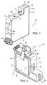
- Fig. 1 shows one perspective view of a print cartridge 10 used in the preferred embodiment. Elements labeled with the same numerals in other figures are identical.
- the outer frame 12 of print cartridge 10 is formed of molded engineering plastic, such as the material marketed under the registered trademark "NORYL” by General Electric Company.
- Side covers 14 may be formed of metal or plastic.
- Datums 16, 17 and 18 affect the position of print cartridge 10 when installed in a carriage in an inkjet printer. Datums 16, 17 and 18 are machined after the nozzle member 20 has been installed on print cartridge 10 to ensure that all four print cartridges 10 (black and three primary color cartridges) installed in the same carriage have their respective nozzles aligned with each other. Additional detail regarding the formation of datums 16, 17 and 18 can be found in U.S. Patent No. 5,408,746, entitled "Datum Formation for Improved Alignment of Multiple Nozzle Members in a Printer.”
- nozzle member 20 consists of a strip of flexible tape 22 having nozzles 24 formed in the tape 22 using laser ablation.
- nozzles 24 formed in the tape 22 using laser ablation.
- One method for forming such nozzles 24 is described in U.S. Patent No. 5,305,015, entitled “Laser Ablated Nozzle Member for Inkjet Printhead,” by Christopher Schantz et al.
- Plastic tabs 26 are used to prevent a particular print cartridge 10 from being inserted into the wrong slot in the carriage. Tabs 26 are different for the black, cyan, magenta, and yellow print cartridges.
- a fill hole 28 is provided for initially filling the ink reservoir in print cartridge 10 by the manufacturer. This hole 28 is later sealed with a steel ball, which was previously intended to be permanent. Such filling will be described later.
- a handle 30 facilitates insertion of print cartridge 10 into, and removal of print cartridge 10 from, the carriage.
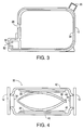
- Fig. 2 is a view of print cartridge 10 of Fig. 1 without side covers 14.
- Figs. 3 and 4 are cross-sections of print cartridge 10 taken along line 3-3 and 4-4, respectively, in Fig. 2.
- Fig. 2 shows the collapsible ink bag 32, which provides a negative internal pressure relative to atmospheric pressure.
- the construction of ink bag 32 is as follows.
- a plastic inner frame 34 (Fig. 3) is provided which generally has the same contours as the rigid outer frame 12.
- Inner frame 34 is preferably formed of a plastic which is more flexible than that used to form outer frame 12 and has a lower melting temperature.
- a suitable plastic material is a soft polyolefin alloy.
- outer frame 12 is used as a portion of the mold when forming inner frame 34. Additional detail regarding the formation of frame 12 and frame 34 is found in European Patent Application 0604712,
- a bow spring 36 (Fig. 4) is provided, which may be cut from a strip of metal such as stainless steel. The apexes of the bight portions of bow spring 36 are spot welded or laser welded to a central portion of rigid metal side plates 38 and 39.
- a pair of flexible ink bag sidewalls 40 and 42 (Fig. 4), formed of a plastic such as ethylene vinyl acetate (EVA) or Mylar, have their peripheral portions heat welded to the edges of inner frame 34 to provide a fluid seal and have their central portions heat welded to Side plates 38 and 39.
- the preferred sidewalls 40 and 42 are formed of a flexible nine-layer material described in U.S. Patent No. 5,450,112.
- the ink bag sidewalls 40 and 42 now oppose side plates 38 and 39 so as to pretension bow spring 36.
- Bow spring 36 now acts as a pressure regulator to provide a relatively constant outward force on the ink bag sidewalls 40 and 42 to provide a negative pressure on the order of -0.1 psi within ink bag 32 (equivalent to a relative pressure of about -3 inches of water).
- An acceptable negative pressure is in the range of approximately -1 to -7 inches of water, with the preferred range being -3 to -5 inches of water.
- ink bag 32 The actual negative pressure required of ink bag 32 is based on various factors, including the nozzle orifice architecture, the geometry of print cartridge 10 (including the outer expansion limits of ink bag 32 as determined by the thickness of print cartridge 10), and the horizontal/vertical orientation of print cartridge 10 when mounted in a printing position in a carriage.
- ink bag 32 will collapse.
- Edge guards 46 and 48 may optionally be bonded to the surface of metal side plates 38 and 39 to prevent the metal edges of plates 38 and 39 from contacting and tearing the ink bag sidewalls 40 and 42.
- Each edge guard may be a thin plastic cover layer adhesively secured to the outer face of side plates 38 and 39 and slightly overlapping the edges.
- a mesh filter (not shown) is also provided on inner frame 34 within ink bag 32 to filter out particles prior to the ink reaching the primary ink channel 50 (Fig. 2) formed in the snout portion of outer frame 12.
- a printhead assembly 52 (Fig. 3) will later be secured to the snout portion of print cartridge 10, and ink channels in the printhead assembly 52 will lead from the primary ink channel 50 into ink ejection chambers on the printhead.
- Ink bag 32 is thus now completely sealed except for ink fill hole 28 and the opening for the primary ink channel 50.
- the amount of ink remaining in ink bag 32 is ascertained by means of an ink level detector, illustrated in Figs. 1 and 2, formed as follows.
- a first paper strip 54 of a solid color, such as green, is secured to ink bag sidewall 42 via an adhesive.
- the end of this strip 54 is then bent over the recessed edge 56 of frame 12 and lies flat against recessed surface 58 of frame 12.
- a strip 60 of a different color, such as black, is provided with a window 62.
- An adhesive on strip 60 is then secured to sidewall 40.
- Strip 60 is bent over the recessed edge 64 of frame 12 and now overlies strip 54 on the recessed surface 58.
- a transparent window 68 which may be a hole or a clear portion, is then secured over the recessed surface 58 by adhesively securing strip 66 to the respective side covers 14 on print cartridge 10.
- the window 62 in strip 60 will expose less and less of the color of strip 54, as seen through window 68, until the green color of strip 54 is no longer exposed through window 68 and only the black strip 60 appears through window 68.
- Print cartridge 10 must then be recharged using ink fill hole 28 and the method described later.
- Suitable negative pressure ink reservoirs include a plastic bellows.
- an ink bag have an external spring, a reservoir having an external pressure regulator, and a rigid reservoir whose internal pressure is regulated by a bubble source.
- the preferred printhead assembly 52 (Fig.3) is described in U.S. Patent No. 5,278,584, entitled “Ink Delivery System for an Inkjet Printhead,” by Brian Keefe et al. Additional information regarding this particular printhead structure may be obtained from European Patent Application 0705694.
- Figs. 5-7 illustrate the preferred method of initially filling print cartridge 10 with ink through ink fill hole 28, best shown in Fig. 1.
- Figs. 5-7 are taken along line 5-5 in Fig. 1 and show outer frame 12, side covers 14, inner frame 34, flexible ink bag sidewalls 40 and 42, and metal side plates 38 and 39.
- the air in ink bag 32 is replaced with CO 2 by simply injecting CO 2 through ink fill hole 28.
- the CO 2 helps prevent air bubbles from forming in ink bag 32 after filling with ink.
- An ink delivery pipe 70 is then inserted through ink fill hole 28, and ink 72 is pumped into the empty ink bag 32 until the ink reaches fill hole 28.
- pipe 70 is inserted to near the bottom of ink bag 32 to minimize ink splashing and the creation of foam.
- a stainless steel ball 74 (Fig. 6) is pressed into ink fill hole 28 by a plunger 76 until ball 74 is seated and firmly secured in fill hole 28, as shown in Fig. 7. Ball 74 now seals ink fill hole 28.
- Print cartridge 10 is then positioned such that its snout is at the highest point, and any excess air is withdrawn through nozzles 24 (Fig. 1) using a vacuum pump sealed with respect to nozzles 24. A sufficient amount of ink is then sucked through nozzles 24 to create the initial negative pressure in ink bag 32 equivalent to about -3 to -4 inches of water. Due to the small diameter of nozzles 24 and the narrow width of the various ink channels, coupled with the ink viscosity, the negative pressure within ink bag 32 does not draw air through nozzles 24. In the preferred embodiment, the capacity of ink bag 32 is around 50 milliliters.
- the completed print cartridge 10 is then inserted into a sliding carriage in an inkjet printer and used in a conventional manner until ink bag 32 becomes progressively depleted, starting from an expanded state to a compressed state, all the time maintaining a negative pressure in ink bag 32.
- the various ink refill systems disclosed herein have a male valve which is used to press any stopper initially blocking ink fill hole 28 into ink bag 32 while maintaining an airtight fluid seal between the external ink reservoir and ink bag 32.
- the ink bag 32 is then recharged.
- the original stopper or a new stopper releasably secured to the tip of the male valve is automatically pulled back into ink fill hole 28 to seat the stopper within ink fill hole 28.
- the stopper is then released from the ink refill system.
- Various embodiments of such an ink refill system are described below.
- an ink refill system 80 is provided with an ink reservoir 82 containing ink.
- This reservoir 82 can take virtually any form.
- Ink reservoir 82 is in fluid communication with the hollow central bore 84 of a male valve 86. Although the central bore 84 of valve 86 would normally be obscured, the partial outline of this bore 84 is illustrated in Fig. 8.
- a rubber sleeve 88 is frictionally fastened over a hole formed in valve 86 which extends into the central bore 84. This hole is shown as hole 90 in Fig. 9, which is an exploded view of ink refill system 80.
- a separate valve tip 92 is connected to valve 86 by a screw thread 94 (Fig. 9) mating with internal threads in tip 92 or by other releasable securing means.
- interlocking fins are used instead of threads to allow a release with only one-quarter turn.
- Suitable snap type couplings are also contemplated. Any suitable method of releasably securing tip 92 to the end of valve 86 to allow tip 92 to be attached and then detached is contemplated by this invention.
- Valve 86 and tip 92 may be metal or plastic.
- the preferred length of valve 86 is on the order of one inch, but other lengths would also be suitable.
- the outside diameter of valve 86 should be slightly greater than the diameter of fill hole 28. In one embodiment, the diameter of valve 86 is about 0.18 inch.
- Fig. 10 is a perspective view of the parts making up the valve portion of ink refill system 80.
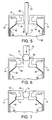
- Figs. 11-14 illustrate the method of using ink refill system 80 to recharge the depleted ink bag 32 in print cartridge 10.
- Fig. 11 which is a cross-sectional view along line 5-5 in Fig. 1, ink refill system 80 is brought together with print cartridge 10 so that tip 92 provides a force on steel ball 74 initially seated in ink fill hole 28. This force pushes ball 74 through hole 28 and into ink bag 32.
- the movement of valve 86 is shown by arrow 94 in Fig. 11. Since inner frame 34 is formed of a relatively soft plastic, the walls of hole 28 deform to allow tip 92 to pass through hole 28.
- valve 86 A further pushing of ink refill system 80 against print cartridge 10 causes sleeve 88 to slide up valve 86, as shown in Fig. 12, so that hole 90 in valve 86 is now in fluid communication with ink bag 32.
- the outer diameter of valve 86 is such that it forms a tight seal with respect to ink fill hole 28.
- ink bag 32 now automatically draws ink 95 through hole 90 from the external ink reservoir into ink bag 32 until either ink bag 32 is completely full or an equilibrium exists between the negative pressure in ink bag 32 and any negative pressure within the external ink reservoir 82 (Fig.8). If there is no positive pressure provided by ink refill system 80, ink bag 32 will not become overfilled so that ink drooling from nozzles 24 (Fig. 1) is prevented.
- valve 86 is then pulled away from print cartridge 10, as shown by arrow 96, so as to seat valve tip 92 within ink fill hole 28.
- Ink refill system 80 is then turned counter-clockwise so as to release valve 86 from tip 92.
- the friction created between tip 92 and the resilient frame 34 defining ink fill hole 28 prevents tip 92 from turning.
- ink refill system 80 has been completely removed leaving only valve tip 92 completely sealing ink fill hole 28.
- the user may simply thread the end of valve 86 into the inner threads of valve tip 92 and again recharge ink bag 32, as shown in Fig. 12.
- a new ink refill system already containing tip 92 may be inserted through ink fill hole 28 and push the old tip 92 into ink bag 32, similar to pushing ball 74 into ink bag 32.
- the same valve tip 92 may be reused many times or a new valve tip 92 may be used while pushing the old valve tip into ink bag 32.
- ink refill system 80 in Fig. 8 may contain a supply of ink for either one recharge or a number of recharges of print cartridge 10.
- rubber sleeve 88 may be spring-mounted onto valve 86 so as to automatically cover hole 90 as the ink refill system 80 is removed from print cartridge 10.
- the print cartridge 10, as provided by the manufacturer, may have a valve tip 92 initially blocking fill hole 28 instead of using a steel ball 74. In such a case, the ink refill system does not need to be provided with its own valve tip 92.
- the external ink reservoir 82 includes a flaccid bag containing ink and having no air within the flaccid bag.
- the amount of ink in the flaccid bag is less than the capacity of ink bag 32 so that the flaccid bag will be completely depleted prior to ink bag 32 being completely full. Thus, a negative pressure will remain in ink bag 32, and there will be no leakage from hole 90 when ink refill system 80 is removed from print cartridge 10.
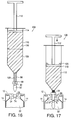
- Fig. 15 is a cross-sectional view along line 5-5 in Fig. 1 showing a different form of valve tip 102 to illustrate that there are many suitable shapes of valve tips which may be used with any of the ink refill systems described herein.
- ink refill system for creating a resealable airtight fluid communication path between ink bag 32 in print cartridge 10 and the external ink supply connected to the ink refill system valve 86.
- the concepts described with respect to Figs. 8-14 may be utilized in a number of embodiments of ink refill systems described below.
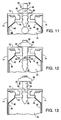
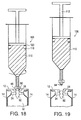
- FIG. 16 A second embodiment ink refill system 106 is shown in Fig. 16 which contains two full ink recharges for print cartridge 10.
- a reusable valve tip 92 is shown mechanically coupled to valve 86.
- a spring-loaded rubber sleeve 88 blocks hole 90 (obscured by sleeve 88 and shown in dashed outline). Spring 100 is shown.
- valve 86 When recharging print cartridge 10, valve 86 is inserted into ink fill hole 28 in print cartridge 10 in the manner described with respect to Fig. 11. It is assumed that the original steel ball 74 is blocking ink fill hole 28.
- the two recharges of ink within ink refill system 106 are shown as first shot 108 and second shot 110.
- a plunger 112 has a seal 114 which slidably engages the sides of the ink reservoir 116.
- valve 86 is inserted through ink fill hole 28 to dislodge steel ball 74 and create an airtight fluid communication path between the ink in ink bag 32 and the ink in ink reservoir 116 via hole 90 formed in valve 86.
- a negative pressure in ink bag 32 provides a force to draw ink 117 from ink reservoir 116
- pressing plunger 112 downward accelerates this transfer of ink into ink bag 32.
- Plunger 112 is pressed into ink reservoir 116 until the bottom portion of seal 114 aligns with a particular grid marking 118 on the side of ink reservoir 116. At this time, ink bag 32 is substantially full.
- plunger 112 is then pulled out of ink reservoir 116 a predetermined amount to match another grid marking 120 so as to pull a predetermined volume of ink out of ink bag 32 to ensure a minimum negative pressure within ink bag 32.
- ink refill system 106 is then partially pulled out of ink fill hole 28 until valve tip 92 seats within ink fill hole 28.
- the spring-loaded sleeve 88 again covers hole 90 to prevent ink leakage.
- Ink refill system 106 is then turned in a counter-clockwise direction to decouple the end of valve 86 from valve tip 92.
- the screw threads 94 (Fig. 19) coupling valve 86 to valve tip 92 require three turns or less to decouple tip 92 from valve 86.
- Fig. 19 shows ink refill system 106 now completely removed from print cartridge 10 and valve tip 92 remaining in ink fill hole 28. As seen, the second shot 110 remains in ink refill system 106 for a next recharge of print cartridge 10 using the same valve tip 92.
- Incorporating fins or other types of gripping mechanisms on the surface of valve tip 92 may be used to provide additional friction between valve tip 92 and the resilient plastic frame 34 defining ink fill hole 28.
- Ink refill system 106 may be provided with three or more charges in alternative embodiments.
- care must be taken to prevent any air ingestion into ink bag 32 and to prevent overfilling of ink bag 32.
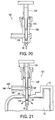
- Fig. 20 is a cross-sectional view of the valve portion of another ink refill system 121 where a supply of ink is connected via a tube 122 at a substantially 90° angle with respect to the male valve 123.
- no plunger is used to accelerate ink from the ink supply into the ink bag 32, but a plunger 124 of a small size is used to insert valve 123 into print cartridge 10.
- a body 125 provides a seal around valve 123.
- Ink refill system 121 is then placed on print cartridge 10 so that valve tip 92 is inserted into the ink fill hole 28. If another tip 92 resided in ink fill hole 28 from a previous recharge of print cartridge 10, then the threaded end of valve 123 would be inserted into the tip 92, and plunger 124 would be turned in a clockwise direction to mechanically couple the end of male valve 123 into the end of tip 92.
- plunger 124 is pressed down so that hole 90 in valve 86 is now located in ink bag 32 and upper hole 128 communicates with pipe 122.
- the negative pressure in ink bag 32 then draws ink 129 from the external ink reservoir through pipe 122, through hole 128, and out of hole 90 into ink bag 32 until the external ink reservoir has been emptied or the negative pressure in ink bag 32 is at equilibrium with any internal pressure in the external ink reservoir.
- Plunger 124 is then lifted to seat valve tip 92 within ink fill hole 28 and turned in a counter-clockwise direction to release the ink refill system 121 from the valve tip 92.
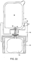
- Figs. 22-24 are cross-sectional views illustrating external ink reservoirs which may be used with any of the valve embodiments previously described.
- a flaccid bag 144 containing a supply of ink is housed in a rigid base 146.
- Valve 86 has its central bore in fluid communication with the ink within flaccid bag 144.
- a rotatable support 148 rests on top of base 146 and receives print cartridge 10 so that print cartridge 10 is in a predetermined optimal position with respect to valve 86.
- Tabs 26 on print cartridge 10, described with respect to Fig. 1 slide between slots 150 on support 148 to ensure that the black, yellow, magenta, or cyan print cartridges (each having a unique combination of tabs 26) receive the proper color ink. Hence, refill systems for each color ink would have a different arrangement of slots 150.
- support 148 and print cartridge 10 are rotated in a clockwise direction to engage valve tip 92 with the end of valve 86, assuming valve tip 92 was already seated within ink fill hole 28 in print cartridge 10.
- Print cartridge 10 is then further pushed down on base 146 to cause valve tip 92 to unseat from ink fill hole 28 and to cause hole 90 to then be located within ink bag 32. This may be done by providing a gap between the bottom of support 148 and the top of base 146 with a spring urging support 148 a first distance away from base 146. When support 148 is pressed against the top of base 146, a latch (or other engaging means) then engages base 146 and support 148 to maintain this recharge position until recharging is complete.
- ink bag 32 in print cartridge 10 draws ink from flaccid bag 144 until flaccid bag 144 is empty or an equilibrium is achieved between the negative pressure in ink bag 32 and the downward pressure of the ink within the ink column below print cartridge 10. Thus, a minimum negative pressure will remain within ink bag 32.
- valve tip 92 is again seated within fill hole 28.
- Print cartridge 10 and support 148 are then rotated counter-clockwise to mechanically decoupled valve tip 92 from the ink refill system.
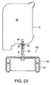
- Fig. 23 is a cross-sectional view illustrating an ink refill system where the external ink reservoir consists of a bellows 154 having either an internal spring or a corrugated exterior which urges the bellows 154 to be in an extended state.
- bellows 154 has a negative internal pressure.
- a rigid base 155 supports bellows 154 and valve 86.
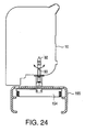
- Valve 86 and valve tip 92 are inserted into ink fill hole 28 as shown in Fig. 24 and described with respect to the other embodiments.
- the negative pressure within ink bag 32 in print cartridge 10 then draws ink from bellows 154 and through hole 90 until the negative pressures in ink bag 32 and in bellows 154 are equal, at which time the transfer of ink automatically ceases.
- Base 155 may be used to support print cartridge 10 during the recharging process.
- the optimum negative pressure in bellows 154 depends upon the intended position of bellows 154 with respect to print cartridge 10 during refilling. For example, if bellows 154 is intended to be above print cartridge 10 while recharging, bellows 154 must be provided with a greater negative internal pressure than if bellows 154 were to be located below print cartridge 10 during recharging.
- Fig. 24 illustrates the compressed bellows 154 after recharging.
- the amount of ink in bellows 154 is on the order of 40 cubic centimeters, and the depth of bellows 154 is on the order of two centimeters.
- bellows 154 may be manually compressed without fear that ink bag 32 will become overfilled.
- Fig. 25 is a cross-sectional view illustrating recharging of print cartridge 10 using ink refill system 106, described with respect to Fig. 16, where the ink fill hole 28 is located at a different location on print cartridge 10.
- This ink fill hole may be in addition to the ink fill hole described with respect to Fig. 1.
- the location of ink fill hole 28 in Fig. 1 is blocked by the ink printer and the carriage so that print cartridge 10 would have to be removed from the ink printer for recharging. If an ink fill hole 28 were located in handle 30 or along the back or top of print cartridge 10, ink fill hole 28 would then be accessible while print cartridge 10 was installed in a carriage.
- Print cartridge 10 can then be recharged without removing print cartridge 10 from the carriage. Such recharging may take place either continuously, intermittently, or when ink bag 32 is substantially depleted of ink.
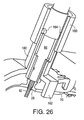
- Numerous structures may be used in conjunction with the ink recharge techniques described herein to ensure that the male valve 86 is substantially perpendicular with respect to ink fill hole 28. This ensures an airtight seal and prevents breaking or bending of the male valve 86. Other designs may ensure that the valve 86 system is mechanically coupled to the valve tip 92 prior to the valve tip 92 being pushed into ink bag 32.
- Fig. 26 is a cut-away view of valve 86 engaging a guide sleeve 160 which has a support portion 162 resting on print cartridge 10 to ensure that sleeve 160 is substantially perpendicular to ink fill hole 28. Knobs 164 extending from valve 86 are blocked by stops on sleeve 160 when valve 86 is forced downward unless valve 86 is turned one-quarter turn to engage valve tip 92. Numerous other embodiments for such a guide means and inadvertent decorking mechanism may be devised. Support portion 162 may also contain slots for interacting with tabs 26 (Fig. 1) on print cartridge 10 to ensure that the correct ink refill system is connected to the proper print cartridge 10.
- a negative pressure ink bag 32 may not be necessary.
- the ink bag 32 in print cartridge 10 will be refilled as long as the refill ink supply is at a pressure greater than the pressure in the ink bag.
- Such a pressure differential may be obtained by raising the external ink supply above the print cartridge or providing the external ink supply with an internal positive pressure.
- the external ink reservoir may take any form and may be a flaccid bag or a rigid vessel which may be vented or nonvented.
- Positive or negative pressure may be achieved using a spring bag, a bellows, a balloon, a syringe, a pressure regulator in series with the external ink reservoir and the print cartridge, or any other known technique.
Description
- This invention relates to inkjet printers and, more particularly, to a technique for refilling inkjet print cartridges with ink and to an ink valve having a releasable tip for a print cartridge recharge system.
- A popular type of inkjet printer contains a scanning carriage for supporting one or more disposable print cartridges. Each disposable print cartridge contains a supply of ink in an ink reservoir, a printhead, and ink channels which lead from the ink reservoir to ink ejection chambers formed on the printhead. An ink ejection element, such as a heater resistor or a piezoelectric element, is located within each ink ejection chamber. The ink ejection elements are selectively fired, causing a droplet of ink to be ejected through a nozzle overlying each activated ink ejection chamber so as to print a pattern of dots on the medium. When such printing takes place at 300 dots per inch (dpi) or greater, the individual dots are indistinguishable from one another and high quality characters and images are printed.
- Once the initial supply of ink in the ink reservoir is depleted, the print cartridge is disposed of and a new print cartridge is inserted in its place. The printhead, however, has a usable life which outlasts the ink supply. Methods have been proposed to refill these single-use-only print cartridges, but such refilling techniques require penetration into the print cartridge body in a manner not intended by the manufacturer and typically require the user to manually inject the ink into the print cartridge. Penetration into the cartridge body typically opens the print cartridge ink bag to the atmosphere, and any back pressure within the ink bag is lost. Additionally, the quality of the refill ink is usually lower than the quality of the original ink. As a result, such refilling frequently results in ink drooling from the nozzles, a messy transfer of ink from the refill kit to the print cartridge reservoir, air pockets forming in the ink channels, poor quality printing resulting from the ink being incompatible with the high speed printing system, and an overall reduction in quality of the printed image.
- What is needed is an improved structure and method for recharging the ink supply in an inkjet print cartridge which is not subject to any of the above-mentioned drawbacks of the existing systems.
- CH-A-681365 discloses a system for use with a print cartridge having an ink fill hole in fluid communication with an ink chamber within said print cartridge comprising: an ink reservoir for containing ink to refill said ink chamber; a hollow needle having receiving opening for receiving ink from said ink reservoir and having a first end, said hollow needle having a transferring opening for transferring ink to said ink chamber in said print cartridge. The needle can be engaged with the closure element of a printer cartridge. The disclosure of this document corresponds generally to the introductory part of claim 1.
- Ink printing systems in accordance with the present invention include a print cartridge, having an ink reservoir and an ink fill hole, and an ink refill system for engaging the print cartridge's ink fill hole and transferring ink to the ink reservoir.
- According to a first aspect of the present invention, there is provided a system for use with a print cartridge having an ink fill hole in fluid communication with an ink chamber within said print cartridge comprising:
- an ink reservoir for containing ink to refill said ink chamber;
- a hollow needle having a receiving opening for receiving ink from said ink reservoir and having a first end, said hollow needle having a transferring opening for transferring ink to said ink chamber in said print cartridge;
- a releasable valve tip configured to be secured to said first end of said hollow needle and readily releasable from said first end, characterised in that said valve tip has an outer surface shape such that said valve tip can be pushed completely through said ink fill hole for refilling said ink chamber via said hollow needle, said outer surface shape of said valve tip also being such that said valve tip seats within said ink fill hole and seals said ink fill hole when said valve tip is pulled back into said ink fill hole when withdrawing said hollow needle from said ink fill hole.
-
- According to a second aspect of the present invention, there is provided a method for recharging a print cartridge comprising the steps of:
- inserting a first end of a hollow needle through an ink fill hole in a print cartridge and into an ink chamber within said print cartridge, an opening in said hollow needle communicating with ink within an ink reservoir, said first end of said hollow needle being releasably connected to a valve tip such that said valve tip is also inserted through said ink fill hole and into said ink chamber;
- transferring ink from said ink reservoir, through said opening; and
- into said ink chamber within said print cartridge;
- withdrawing said hollow needle from said ink chamber until said valve tip seats within said ink fill hole to seal said ink chamber; and
- disengaging said first end of said hollow needle from said valve tip.
-
- In a preferred embodiment, the ink reservoir in the print cartridge consists of a spring-loaded collapsible ink bag,
where the spring urges the sides of the ink bag apart and thus maintains a negative pressure within the ink bag relative to ambient pressure. This negative pressure prevents ink drooling from the nozzles. As the ink is depleted during use of the print cartridge, the ink bag progressively collapses and overcomes the spring force. - An ink fill hole extends through the print cartridge body and into the ink bag. This ink fill hole is used by the manufacturer when initially filling the ink bag with ink. The ink fill hole has a stopper blocking the hole to prevent ink leakage through the hole.
- An ink refill system containing a supply of ink has a male valve, resembling a hollow needle, which is inserted through the ink fill hole and pushes the stopper into the ink bag. The male valve creates an airtight fluid communication path between the ink bag and the ink supply in the ink refill system.
- The negative pressure within the print cartridge ink bag then draws the ink from the ink refill system into the ink bag until the ink bag is substantially full. The ink refill system is then removed from the print cartridge. The male valve of the ink refill system has a releasable tip which is pulled into the ink fill hole to seal the ink fill hole. The tip is then released from the male valve such as by unscrewing the male valve from the tip. Thus, the negative pressure in the ink bag is maintained. The print cartridge may again be used for printing. The tip can be reused for subsequent rechargings.
- Fig. 1 is a perspective view of a print cartridge incorporating an ink fill hole.
- Fig. 2 is a perspective view of the print cartridge of Fig. 1 after assembly and prior to side covers being connected.
- Fig. 3 is a cross-sectional view of the print cartridge of Fig. 2 taken along line 3-3 in Fig. 2.
- Fig. 4 is a cross-sectional view of the print cartridge of Fig. 2 taken along line 4-4 in Fig. 2.
- Fig. 5 is a cross-sectional view of the print cartridge of Fig. 1 taken along line 5-5 in Fig. 1 illustrating the initial filling of the print cartridge with ink.
- Figs. 6 and 7 illustrate the insertion of a steel ball in the ink fill hole for sealing the fill hole.
- Fig. 8 is a side view of the valve portion of an ink refill system for recharging the print cartridge of Fig. 1.
- Fig. 9 is an exploded view of the ink refill system of Fig. 8.
- Fig. 10 is a perspective exploded view of the ink refill system of Fig. 8.
- Fig. 11 is a cross-sectional view along line 5-5 in Fig. 1 showing the insertion of a valve into the ink fill hole of the print cartridge of Fig. 1.
- Figs. 12, 13 and 14 illustrate the techniques used to recharge the print cartridge of Fig. 1 and to reseal the negative pressure ink bag within the print cartridge.
- Fig. 15 illustrates another design for the valve tip.
- Figs. 16, 17, 18, and 19 illustrate an embodiment of a syringe-type ink refill system for use with the print cartridge of Fig. 1.
- Fig. 20 is a cross-sectional view of another embodiment ink refill system.
- Fig. 21 is a cross-sectional view of the print cartridge of Fig. 1 along line 20-20 in Fig. 1 while being recharged by the ink refill system of Fig. 20.
- Fig. 22 is a cross-sectional view of the print cartridge of Fig. 1 along line 20-20 in Fig. 1 illustrating the recharging of the print cartridge using a valve connected to a flaccid bag containing ink and using a rotatable print cartridge support.
- Figs. 23 and 24 are cross-sectional views of the print cartridge of Fig. 1 along line 20-20 in Fig. 1 illustrating the recharging of the print cartridge using a valve connected to a compressible bellows.
- Fig. 25 is a cross-sectional view of a print cartridge illustrating the recharging of the print cartridge through an ink fill hole which is accessible when the print cartridge is installed in a printer.
- Fig. 26 is a partial cut-away view of a guide sleeve and support for the ink refill system valve when connected to the print cartridge.
-
- Fig. 1 shows one perspective view of a
print cartridge 10 used in the preferred embodiment. Elements labeled with the same numerals in other figures are identical. Theouter frame 12 ofprint cartridge 10 is formed of molded engineering plastic, such as the material marketed under the registered trademark "NORYL" by General Electric Company. Side covers 14 may be formed of metal or plastic.Datums print cartridge 10 when installed in a carriage in an inkjet printer.Datums nozzle member 20 has been installed onprint cartridge 10 to ensure that all four print cartridges 10 (black and three primary color cartridges) installed in the same carriage have their respective nozzles aligned with each other. Additional detail regarding the formation ofdatums - In the preferred embodiment,
nozzle member 20 consists of a strip offlexible tape 22 havingnozzles 24 formed in thetape 22 using laser ablation. One method for formingsuch nozzles 24 is described in U.S. Patent No. 5,305,015, entitled "Laser Ablated Nozzle Member for Inkjet Printhead," by Christopher Schantz et al. -
Plastic tabs 26 are used to prevent aparticular print cartridge 10 from being inserted into the wrong slot in the carriage.Tabs 26 are different for the black, cyan, magenta, and yellow print cartridges. - A
fill hole 28 is provided for initially filling the ink reservoir inprint cartridge 10 by the manufacturer. Thishole 28 is later sealed with a steel ball, which was previously intended to be permanent. Such filling will be described later. - A
handle 30 facilitates insertion ofprint cartridge 10 into, and removal ofprint cartridge 10 from, the carriage. - Fig. 2 is a view of
print cartridge 10 of Fig. 1 without side covers 14. Figs. 3 and 4 are cross-sections ofprint cartridge 10 taken along line 3-3 and 4-4, respectively, in Fig. 2. - Fig. 2 shows the
collapsible ink bag 32, which provides a negative internal pressure relative to atmospheric pressure. The construction ofink bag 32 is as follows. - A plastic inner frame 34 (Fig. 3) is provided which generally has the same contours as the rigid
outer frame 12.Inner frame 34 is preferably formed of a plastic which is more flexible than that used to formouter frame 12 and has a lower melting temperature. A suitable plastic material is a soft polyolefin alloy. In the preferred embodiment,outer frame 12 is used as a portion of the mold when forminginner frame 34. Additional detail regarding the formation offrame 12 andframe 34 is found in European Patent Application 0604712, - A bow spring 36 (Fig. 4) is provided, which may be cut from a strip of metal such as stainless steel. The apexes of the bight portions of
bow spring 36 are spot welded or laser welded to a central portion of rigidmetal side plates inner frame 34 to provide a fluid seal and have their central portions heat welded toSide plates preferred sidewalls - The ink bag sidewalls 40 and 42 now oppose
side plates pretension bow spring 36.Bow spring 36 now acts as a pressure regulator to provide a relatively constant outward force on the ink bag sidewalls 40 and 42 to provide a negative pressure on the order of -0.1 psi within ink bag 32 (equivalent to a relative pressure of about -3 inches of water). An acceptable negative pressure is in the range of approximately -1 to -7 inches of water, with the preferred range being -3 to -5 inches of water. - The actual negative pressure required of
ink bag 32 is based on various factors, including the nozzle orifice architecture, the geometry of print cartridge 10 (including the outer expansion limits ofink bag 32 as determined by the thickness of print cartridge 10), and the horizontal/vertical orientation ofprint cartridge 10 when mounted in a printing position in a carriage. - As ink is withdrawn from
print cartridge 10,ink bag 32 will collapse. - Edge guards 46 and 48 (Fig. 4) may optionally be bonded to the surface of
metal side plates plates side plates - A mesh filter (not shown) is also provided on
inner frame 34 withinink bag 32 to filter out particles prior to the ink reaching the primary ink channel 50 (Fig. 2) formed in the snout portion ofouter frame 12. A printhead assembly 52 (Fig. 3) will later be secured to the snout portion ofprint cartridge 10, and ink channels in theprinthead assembly 52 will lead from theprimary ink channel 50 into ink ejection chambers on the printhead. -
Ink bag 32 is thus now completely sealed except forink fill hole 28 and the opening for theprimary ink channel 50. - In the preferred embodiment, the amount of ink remaining in
ink bag 32 is ascertained by means of an ink level detector, illustrated in Figs. 1 and 2, formed as follows. Afirst paper strip 54 of a solid color, such as green, is secured toink bag sidewall 42 via an adhesive. The end of thisstrip 54 is then bent over the recessededge 56 offrame 12 and lies flat against recessedsurface 58 offrame 12. Astrip 60 of a different color, such as black, is provided with awindow 62. An adhesive onstrip 60 is then secured tosidewall 40.Strip 60 is bent over the recessededge 64 offrame 12 and now overliesstrip 54 on the recessedsurface 58. Once the side plates 14 (Fig. 1) are secured to printcartridge 10, a strip 66 (Fig. 1) having atransparent window 68, which may be a hole or a clear portion, is then secured over the recessedsurface 58 byadhesively securing strip 66 to the respective side covers 14 onprint cartridge 10. As the flexible ink bag sidewalls 40 and 42 become closer together as ink is depleted fromink bag 32, thewindow 62 instrip 60 will expose less and less of the color ofstrip 54, as seen throughwindow 68, until the green color ofstrip 54 is no longer exposed throughwindow 68 and only theblack strip 60 appears throughwindow 68.Print cartridge 10 must then be recharged usingink fill hole 28 and the method described later. - Additional information regarding the construction of the spring-loaded ink bag can be found in European Patent Application 745482.
- Other suitable negative pressure ink reservoirs include a plastic bellows. an ink bag have an external spring, a reservoir having an external pressure regulator, and a rigid reservoir whose internal pressure is regulated by a bubble source.
- The preferred printhead assembly 52 (Fig.3) is described in U.S. Patent No. 5,278,584, entitled "Ink Delivery System for an Inkjet Printhead," by Brian Keefe et al. Additional information regarding this particular printhead structure may be obtained from European Patent Application 0705694.
- Figs. 5-7 illustrate the preferred method of initially filling
print cartridge 10 with ink throughink fill hole 28, best shown in Fig. 1. Figs. 5-7 are taken along line 5-5 in Fig. 1 and showouter frame 12, side covers 14,inner frame 34, flexible ink bag sidewalls 40 and 42, andmetal side plates ink bag 32 is replaced with CO2 by simply injecting CO2 throughink fill hole 28. As described later, the CO2 helps prevent air bubbles from forming inink bag 32 after filling with ink. Anink delivery pipe 70 is then inserted throughink fill hole 28, andink 72 is pumped into theempty ink bag 32 until the ink reachesfill hole 28. In the preferred method,pipe 70 is inserted to near the bottom ofink bag 32 to minimize ink splashing and the creation of foam. - Once
ink bag 32 is full, a stainless steel ball 74 (Fig. 6) is pressed intoink fill hole 28 by aplunger 76 untilball 74 is seated and firmly secured infill hole 28, as shown in Fig. 7.Ball 74 now seals ink fillhole 28. -
Print cartridge 10 is then positioned such that its snout is at the highest point, and any excess air is withdrawn through nozzles 24 (Fig. 1) using a vacuum pump sealed with respect tonozzles 24. A sufficient amount of ink is then sucked throughnozzles 24 to create the initial negative pressure inink bag 32 equivalent to about -3 to -4 inches of water. Due to the small diameter ofnozzles 24 and the narrow width of the various ink channels, coupled with the ink viscosity, the negative pressure withinink bag 32 does not draw air throughnozzles 24. In the preferred embodiment, the capacity ofink bag 32 is around 50 milliliters. - The completed
print cartridge 10 is then inserted into a sliding carriage in an inkjet printer and used in a conventional manner untilink bag 32 becomes progressively depleted, starting from an expanded state to a compressed state, all the time maintaining a negative pressure inink bag 32. - Preferred devices for recharging
print cartridge 10 via ink fill hole 28 (or another ink fill hole) will now be described. - The various ink refill systems disclosed herein have a male valve which is used to press any stopper initially blocking
ink fill hole 28 intoink bag 32 while maintaining an airtight fluid seal between the external ink reservoir andink bag 32. Theink bag 32 is then recharged. When the ink refill system is withdrawn, the original stopper or a new stopper releasably secured to the tip of the male valve is automatically pulled back intoink fill hole 28 to seat the stopper withinink fill hole 28. The stopper is then released from the ink refill system. Various embodiments of such an ink refill system are described below. - In Fig. 8, an
ink refill system 80 is provided with anink reservoir 82 containing ink. Thisreservoir 82 can take virtually any form.Ink reservoir 82 is in fluid communication with the hollow central bore 84 of amale valve 86. Although thecentral bore 84 ofvalve 86 would normally be obscured, the partial outline of this bore 84 is illustrated in Fig. 8. - A
rubber sleeve 88 is frictionally fastened over a hole formed invalve 86 which extends into thecentral bore 84. This hole is shown ashole 90 in Fig. 9, which is an exploded view ofink refill system 80. - A
separate valve tip 92 is connected tovalve 86 by a screw thread 94 (Fig. 9) mating with internal threads intip 92 or by other releasable securing means. In one embodiment, interlocking fins are used instead of threads to allow a release with only one-quarter turn. Suitable snap type couplings are also contemplated. Any suitable method of releasably securingtip 92 to the end ofvalve 86 to allowtip 92 to be attached and then detached is contemplated by this invention. -
Valve 86 andtip 92 may be metal or plastic. The preferred length ofvalve 86 is on the order of one inch, but other lengths would also be suitable. The outside diameter ofvalve 86 should be slightly greater than the diameter offill hole 28. In one embodiment, the diameter ofvalve 86 is about 0.18 inch. - Fig. 10 is a perspective view of the parts making up the valve portion of
ink refill system 80. - Figs. 11-14 illustrate the method of using
ink refill system 80 to recharge the depletedink bag 32 inprint cartridge 10. - In Fig. 11, which is a cross-sectional view along line 5-5 in Fig. 1,
ink refill system 80 is brought together withprint cartridge 10 so thattip 92 provides a force onsteel ball 74 initially seated in ink fillhole 28. This force pushesball 74 throughhole 28 and intoink bag 32. The movement ofvalve 86 is shown byarrow 94 in Fig. 11. Sinceinner frame 34 is formed of a relatively soft plastic, the walls ofhole 28 deform to allowtip 92 to pass throughhole 28. - A further pushing of
ink refill system 80 againstprint cartridge 10 causessleeve 88 to slide upvalve 86, as shown in Fig. 12, so thathole 90 invalve 86 is now in fluid communication withink bag 32. The outer diameter ofvalve 86 is such that it forms a tight seal with respect to ink fillhole 28. - The negative pressure internal to
ink bag 32 now automatically drawsink 95 throughhole 90 from the external ink reservoir intoink bag 32 until eitherink bag 32 is completely full or an equilibrium exists between the negative pressure inink bag 32 and any negative pressure within the external ink reservoir 82 (Fig.8). If there is no positive pressure provided byink refill system 80,ink bag 32 will not become overfilled so that ink drooling from nozzles 24 (Fig. 1) is prevented. - As shown in Fig. 13,
valve 86 is then pulled away fromprint cartridge 10, as shown byarrow 96, so as toseat valve tip 92 withinink fill hole 28.Ink refill system 80 is then turned counter-clockwise so as to releasevalve 86 fromtip 92. The friction created betweentip 92 and theresilient frame 34 definingink fill hole 28 preventstip 92 from turning. - As shown in Fig. 14,
ink refill system 80 has been completely removed leaving onlyvalve tip 92 completely sealingink fill hole 28. For a next recharge ofprint cartridge 10, the user may simply thread the end ofvalve 86 into the inner threads ofvalve tip 92 and again rechargeink bag 32, as shown in Fig. 12. Alternatively, a new ink refill system already containingtip 92 may be inserted throughink fill hole 28 and push theold tip 92 intoink bag 32, similar to pushingball 74 intoink bag 32. Thus, thesame valve tip 92 may be reused many times or anew valve tip 92 may be used while pushing the old valve tip intoink bag 32. Hence,ink refill system 80 in Fig. 8 may contain a supply of ink for either one recharge or a number of recharges ofprint cartridge 10. - If
ink refill system 80 contains a number of recharges,rubber sleeve 88 may be spring-mounted ontovalve 86 so as to automatically coverhole 90 as theink refill system 80 is removed fromprint cartridge 10. - The
print cartridge 10, as provided by the manufacturer, may have avalve tip 92 initially blockingfill hole 28 instead of using asteel ball 74. In such a case, the ink refill system does not need to be provided with itsown valve tip 92. - In one embodiment, the
external ink reservoir 82 includes a flaccid bag containing ink and having no air within the flaccid bag. The amount of ink in the flaccid bag is less than the capacity ofink bag 32 so that the flaccid bag will be completely depleted prior toink bag 32 being completely full. Thus, a negative pressure will remain inink bag 32, and there will be no leakage fromhole 90 whenink refill system 80 is removed fromprint cartridge 10. - Fig. 15 is a cross-sectional view along line 5-5 in Fig. 1 showing a different form of
valve tip 102 to illustrate that there are many suitable shapes of valve tips which may be used with any of the ink refill systems described herein. - Thus, an ink refill system has been described for creating a resealable airtight fluid communication path between
ink bag 32 inprint cartridge 10 and the external ink supply connected to the inkrefill system valve 86. The concepts described with respect to Figs. 8-14 may be utilized in a number of embodiments of ink refill systems described below. - A second embodiment
ink refill system 106 is shown in Fig. 16 which contains two full ink recharges forprint cartridge 10. Areusable valve tip 92 is shown mechanically coupled tovalve 86. A spring-loadedrubber sleeve 88 blocks hole 90 (obscured bysleeve 88 and shown in dashed outline).Spring 100 is shown. - When recharging
print cartridge 10,valve 86 is inserted intoink fill hole 28 inprint cartridge 10 in the manner described with respect to Fig. 11. It is assumed that theoriginal steel ball 74 is blockingink fill hole 28. The two recharges of ink withinink refill system 106 are shown asfirst shot 108 andsecond shot 110. Aplunger 112 has aseal 114 which slidably engages the sides of theink reservoir 116. - In Fig. 17,
valve 86 is inserted throughink fill hole 28 to dislodgesteel ball 74 and create an airtight fluid communication path between the ink inink bag 32 and the ink inink reservoir 116 viahole 90 formed invalve 86. Although a negative pressure inink bag 32 provides a force to drawink 117 fromink reservoir 116,pressing plunger 112 downward accelerates this transfer of ink intoink bag 32.Plunger 112 is pressed intoink reservoir 116 until the bottom portion ofseal 114 aligns with a particular grid marking 118 on the side ofink reservoir 116. At this time,ink bag 32 is substantially full. - To ensure a minimum back pressure in
ink bag 32,plunger 112 is then pulled out of ink reservoir 116 a predetermined amount to match another grid marking 120 so as to pull a predetermined volume of ink out ofink bag 32 to ensure a minimum negative pressure withinink bag 32. - As shown in Fig. 18,
ink refill system 106 is then partially pulled out of ink fillhole 28 untilvalve tip 92 seats withinink fill hole 28. The spring-loadedsleeve 88 again covershole 90 to prevent ink leakage.Ink refill system 106 is then turned in a counter-clockwise direction to decouple the end ofvalve 86 fromvalve tip 92. Preferably, the screw threads 94 (Fig. 19)coupling valve 86 tovalve tip 92 require three turns or less to decoupletip 92 fromvalve 86. - Fig. 19 shows
ink refill system 106 now completely removed fromprint cartridge 10 andvalve tip 92 remaining in ink fillhole 28. As seen, thesecond shot 110 remains inink refill system 106 for a next recharge ofprint cartridge 10 using thesame valve tip 92. - Incorporating fins or other types of gripping mechanisms on the surface of
valve tip 92 may be used to provide additional friction betweenvalve tip 92 and theresilient plastic frame 34 definingink fill hole 28.Ink refill system 106 may be provided with three or more charges in alternative embodiments. - In all embodiments, care must be taken to prevent any air ingestion into
ink bag 32 and to prevent overfilling ofink bag 32. - Fig. 20 is a cross-sectional view of the valve portion of another
ink refill system 121 where a supply of ink is connected via atube 122 at a substantially 90° angle with respect to themale valve 123. In this embodiment, no plunger is used to accelerate ink from the ink supply into theink bag 32, but aplunger 124 of a small size is used to insertvalve 123 intoprint cartridge 10. Abody 125 provides a seal aroundvalve 123. -
Ink refill system 121 is then placed onprint cartridge 10 so thatvalve tip 92 is inserted into theink fill hole 28. If anothertip 92 resided in ink fillhole 28 from a previous recharge ofprint cartridge 10, then the threaded end ofvalve 123 would be inserted into thetip 92, andplunger 124 would be turned in a clockwise direction to mechanically couple the end ofmale valve 123 into the end oftip 92. - In Fig. 21,
plunger 124 is pressed down so thathole 90 invalve 86 is now located inink bag 32 andupper hole 128 communicates withpipe 122. The negative pressure inink bag 32 then drawsink 129 from the external ink reservoir throughpipe 122, throughhole 128, and out ofhole 90 intoink bag 32 until the external ink reservoir has been emptied or the negative pressure inink bag 32 is at equilibrium with any internal pressure in the external ink reservoir. -
Plunger 124 is then lifted toseat valve tip 92 withinink fill hole 28 and turned in a counter-clockwise direction to release theink refill system 121 from thevalve tip 92. - Figs. 22-24 are cross-sectional views illustrating external ink reservoirs which may be used with any of the valve embodiments previously described.
- In Fig. 22, a
flaccid bag 144 containing a supply of ink is housed in arigid base 146.Valve 86, previously described, has its central bore in fluid communication with the ink withinflaccid bag 144. - A
rotatable support 148 rests on top ofbase 146 and receivesprint cartridge 10 so thatprint cartridge 10 is in a predetermined optimal position with respect tovalve 86.Tabs 26 onprint cartridge 10, described with respect to Fig. 1, slide betweenslots 150 onsupport 148 to ensure that the black, yellow, magenta, or cyan print cartridges (each having a unique combination of tabs 26) receive the proper color ink.
Hence, refill systems for each color ink would have a different arrangement ofslots 150. - Once
print cartridge 10 is properly placed withinsupport 148,support 148 andprint cartridge 10 are rotated in a clockwise direction to engagevalve tip 92 with the end ofvalve 86, assumingvalve tip 92 was already seated withinink fill hole 28 inprint cartridge 10. -
Print cartridge 10 is then further pushed down onbase 146 to causevalve tip 92 to unseat from ink fillhole 28 and to causehole 90 to then be located withinink bag 32. This may be done by providing a gap between the bottom ofsupport 148 and the top ofbase 146 with a spring urging support 148 a first distance away frombase 146. Whensupport 148 is pressed against the top ofbase 146, a latch (or other engaging means) then engagesbase 146 andsupport 148 to maintain this recharge position until recharging is complete. The negative pressure withinink bag 32 inprint cartridge 10 draws ink fromflaccid bag 144 untilflaccid bag 144 is empty or an equilibrium is achieved between the negative pressure inink bag 32 and the downward pressure of the ink within the ink column belowprint cartridge 10. Thus, a minimum negative pressure will remain withinink bag 32. - After recharging, the latch is triggered so that
valve tip 92 is again seated withinfill hole 28.Print cartridge 10 andsupport 148 are then rotated counter-clockwise to mechanically decoupledvalve tip 92 from the ink refill system. - Fig. 23 is a cross-sectional view illustrating an ink refill system where the external ink reservoir consists of a
bellows 154 having either an internal spring or a corrugated exterior which urges thebellows 154 to be in an extended state. Thus, bellows 154 has a negative internal pressure. Arigid base 155 supports bellows 154 andvalve 86. -
Valve 86 andvalve tip 92 are inserted intoink fill hole 28 as shown in Fig. 24 and described with respect to the other embodiments. The negative pressure withinink bag 32 inprint cartridge 10 then draws ink frombellows 154 and throughhole 90 until the negative pressures inink bag 32 and inbellows 154 are equal, at which time the transfer of ink automatically ceases.Base 155 may be used to supportprint cartridge 10 during the recharging process. The optimum negative pressure inbellows 154 depends upon the intended position ofbellows 154 with respect toprint cartridge 10 during refilling. For example, ifbellows 154 is intended to be aboveprint cartridge 10 while recharging, bellows 154 must be provided with a greater negative internal pressure than ifbellows 154 were to be located belowprint cartridge 10 during recharging. - Fig. 24 illustrates the compressed bellows 154 after recharging. In the preferred embodiment, the amount of ink in
bellows 154 is on the order of 40 cubic centimeters, and the depth ofbellows 154 is on the order of two centimeters. - If the amount of ink in
bellows 154 is less than the capacity ofink bag 32, bellows 154 may be manually compressed without fear thatink bag 32 will become overfilled. - Fig. 25 is a cross-sectional view illustrating recharging of
print cartridge 10 usingink refill system 106, described with respect to Fig. 16, where theink fill hole 28 is located at a different location onprint cartridge 10. This ink fill hole may be in addition to the ink fill hole described with respect to Fig. 1. Whenprint cartridge 10 is installed in a conventional carriage, the location of ink fillhole 28 in Fig. 1 is blocked by the ink printer and the carriage so thatprint cartridge 10 would have to be removed from the ink printer for recharging. If anink fill hole 28 were located inhandle 30 or along the back or top ofprint cartridge 10, ink fillhole 28 would then be accessible whileprint cartridge 10 was installed in a carriage.Print cartridge 10 can then be recharged without removingprint cartridge 10 from the carriage. Such recharging may take place either continuously, intermittently, or whenink bag 32 is substantially depleted of ink. - The ink refill technique shown in Fig. 25 is identical to that shown in Figs. 16-18, and the description will not be repeated. Identical numerals in the figures refer to identical structures.
- Numerous structures may be used in conjunction with the ink recharge techniques described herein to ensure that the
male valve 86 is substantially perpendicular with respect to ink fillhole 28. This ensures an airtight seal and prevents breaking or bending of themale valve 86. Other designs may ensure that thevalve 86 system is mechanically coupled to thevalve tip 92 prior to thevalve tip 92 being pushed intoink bag 32. - Fig. 26 is a cut-away view of
valve 86 engaging aguide sleeve 160 which has asupport portion 162 resting onprint cartridge 10 to ensure thatsleeve 160 is substantially perpendicular to ink fillhole 28.Knobs 164 extending fromvalve 86 are blocked by stops onsleeve 160 whenvalve 86 is forced downward unlessvalve 86 is turned one-quarter turn to engagevalve tip 92. Numerous other embodiments for such a guide means and inadvertent decorking mechanism may be devised.Support portion 162 may also contain slots for interacting with tabs 26 (Fig. 1) onprint cartridge 10 to ensure that the correct ink refill system is connected to theproper print cartridge 10. - While particular embodiments of the present invention have been shown and described, it will be obvious to those skilled in the art that changes and modifications may be made without departing from this invention in its broader aspects as defined in the appended claims. For example, although a negative
pressure ink bag 32 is described, a negativepressure ink bag 32 may not be necessary. Theink bag 32 inprint cartridge 10 will be refilled as long as the refill ink supply is at a pressure greater than the pressure in the ink bag. Such a pressure differential may be obtained by raising the external ink supply above the print cartridge or providing the external ink supply with an internal positive pressure. The external ink reservoir may take any form and may be a flaccid bag or a rigid vessel which may be vented or nonvented. Positive or negative pressure may be achieved using a spring bag, a bellows, a balloon, a syringe, a pressure regulator in series with the external ink reservoir and the print cartridge, or any other known technique.
Claims (10)
- A system for use with a print cartridge (10) having an ink fill hole (28) in fluid communication with an ink chamber (32) within said print cartridge comprising:an ink reservoir (82) for containing ink to refill said ink chamber (32);a hollow needle (86) having a receiving opening (84) for receiving ink from said ink reservoir and having a first end, said hollow needle having a transferring opening for transferring ink to said ink chamber (32) in said print cartridge;a releasable valve tip (92) configured to be secured to said first end of said hollow needle and readily releasable from said first end, characterised in that said valve tip has an outer surface shape such that said valve tip can be pushed completely through said ink fill hole for refilling said ink chamber (32) via said hollow needle, said outer surface shape of said valve tip also being such that said valve tip seats within said ink fill hole and seals said ink fill hole when said valve tip is pulled back into said ink fill hole when withdrawing said hollow needle from said ink fill hole.
- The system of Claim 1 wherein said first end of said hollow needle (86) has a first engaging means (94) for coupling to a second engaging means on said valve tip (92) for allowing securing said valve tip to said first end and releasing said valve tip from said first end.
- The system of Claim 2 wherein said first engaging means (94) is a first screw thread and said second engaging means is a second screw thread.
- The system of Claim 1 wherein a diameter of said hollow needle (86) is such that said hollow needle creates an airtight seal around a periphery of said ink fill hole (28) of said print cartridge (10) when inserted through said ink fill hole.
- The system of Claim 1 wherein said valve tip (92) has a recessed portion in its outer surface which is engaged by a periphery of said ink fill hole (28), when said valve tip is seated within said ink fill hole, to form an airtight seal of said ink fill hole.
- The system of Claim 1 further comprising said print cartridge (10)
- The system of Claim 6 wherein said ink chamber comprises an ink bag (32) which is at a negative pressure relative to the atmosphere, and wherein said hollow needle (86) creates an airtight seal around a periphery of said ink fill hole (28) when inserted through said ink fill hole so that said ink bag becomes recharged with ink from said ink reservoir (82) without air entering said ink bag.
- A method for recharging a print cartridge comprising the steps of:inserting a first end of a hollow needle (86) through an ink fill hole (28) in a print cartridge (10) and into an ink chamber (32) within said print cartridge, an opening (90) in said hollow needle communicating with ink within an ink reservoir (82), said first end of said hollow needle being releasably connected to a valve tip (92) such that said valve tip is also inserted through said ink fill hole and into said ink chamber;transferring ink from said ink reservoir, through said opening; and into said ink chamber within said print cartridge;withdrawing said hollow needle from said ink chamber until said valve tip seats within said ink fill hole to seal said ink chamber: anddisengaging said first end of said hollow needle from said valve tip.
- The method of Claim 8 wherein said step of disengaging said first end of said hollow needle (86) from said valve tip (92) comprises the step of rotating said hollow needle with respect to said valve tip to disengage said first end from said valve tip.
- The method of Claim 8 further comprising the steps of engaging said first end of said hollow needle (86) with said valve tip (92) while said valve tip is seated within said ink fill hole (28) of said print cartridge (10), prior to inserting said first end of said hollow needle through said ink fill hole.
Applications Claiming Priority (2)
| Application Number | Priority Date | Filing Date | Title |
|---|---|---|---|
| US618238 | 1996-03-14 | ||
| US08/618,238 US5886719A (en) | 1996-03-14 | 1996-03-14 | Ink valve having a releasable tip for a print cartridge recharge system |
Publications (2)
| Publication Number | Publication Date |
|---|---|
| EP0795409A1 EP0795409A1 (en) | 1997-09-17 |
| EP0795409B1 true EP0795409B1 (en) | 1999-12-15 |
Family
ID=24476888
Family Applications (1)
| Application Number | Title | Priority Date | Filing Date |
|---|---|---|---|
| EP97301690A Expired - Lifetime EP0795409B1 (en) | 1996-03-14 | 1997-03-13 | Printing systems |
Country Status (5)
| Country | Link |
|---|---|
| US (2) | US5886719A (en) |
| EP (1) | EP0795409B1 (en) |
| JP (1) | JP3982865B2 (en) |
| KR (1) | KR100390126B1 (en) |
| DE (1) | DE69700931T2 (en) |
Cited By (3)
| Publication number | Priority date | Publication date | Assignee | Title |
|---|---|---|---|---|
| US6203759B1 (en) | 1996-05-31 | 2001-03-20 | Packard Instrument Company | Microvolume liquid handling system |
| US6521187B1 (en) | 1996-05-31 | 2003-02-18 | Packard Instrument Company | Dispensing liquid drops onto porous brittle substrates |
| US6537817B1 (en) | 1993-05-31 | 2003-03-25 | Packard Instrument Company | Piezoelectric-drop-on-demand technology |
Families Citing this family (53)
| Publication number | Priority date | Publication date | Assignee | Title |
|---|---|---|---|---|
| US6170937B1 (en) * | 1997-01-21 | 2001-01-09 | Hewlett-Packard Company | Ink container refurbishment method |
| US5886719A (en) * | 1996-03-14 | 1999-03-23 | Hewlett-Packard Company | Ink valve having a releasable tip for a print cartridge recharge system |
| JPH10193630A (en) * | 1997-01-08 | 1998-07-28 | Brother Ind Ltd | Liquid ink supplying device |
| ATE267707T1 (en) * | 1999-03-29 | 2004-06-15 | Seiko Epson Corp | METHOD AND DEVICE FOR FILLING INK CARTRIDGES WITH INK |
| JP4370486B2 (en) * | 1999-10-19 | 2009-11-25 | 富士フイルム株式会社 | Inkjet head and printer |
| US6439707B1 (en) * | 2001-01-25 | 2002-08-27 | Hewlett-Packard Company | Anti-spill fluid filling port |
| JP4193435B2 (en) | 2002-07-23 | 2008-12-10 | ブラザー工業株式会社 | Ink cartridge and ink filling method thereof |
| US6799610B2 (en) * | 2002-09-20 | 2004-10-05 | Kenneth Yuen | Method and apparatus for refilling an ink cartridge |
| US6722400B1 (en) | 2002-12-17 | 2004-04-20 | Eastman Kodak Company | Apparatus for filling and degassing a pouch |
| US6725888B1 (en) | 2002-12-17 | 2004-04-27 | Eastman Kodak Company | Method of accurately filling and degassing a pouch |
| KR100487585B1 (en) * | 2002-12-20 | 2005-05-03 | 주식회사 프린톤 | Method of refilling ink in an ink cartridge for an inkjet printer |
| US20040257412A1 (en) * | 2003-06-18 | 2004-12-23 | Anderson James D. | Sealed fluidic interfaces for an ink source regulator for an inkjet printer |
| US7448734B2 (en) * | 2004-01-21 | 2008-11-11 | Silverbrook Research Pty Ltd | Inkjet printer cartridge with pagewidth printhead |
| US7232208B2 (en) | 2004-01-21 | 2007-06-19 | Silverbrook Research Pty Ltd | Inkjet printer cartridge refill dispenser with plunge action |
| US7121655B2 (en) * | 2004-01-21 | 2006-10-17 | Silverbrook Research Pty Ltd | Inkjet printer cartridge refill dispenser |
| US7328985B2 (en) * | 2004-01-21 | 2008-02-12 | Silverbrook Research Pty Ltd | Inkjet printer cartridge refill dispenser with security mechanism |
| US7524016B2 (en) * | 2004-01-21 | 2009-04-28 | Silverbrook Research Pty Ltd | Cartridge unit having negatively pressurized ink storage |
| US20050157112A1 (en) | 2004-01-21 | 2005-07-21 | Silverbrook Research Pty Ltd | Inkjet printer cradle with shaped recess for receiving a printer cartridge |
| US7303267B2 (en) * | 2004-04-02 | 2007-12-04 | Kenneth Yuen | Actuator for automatic ink refill system |
| US20050225592A1 (en) * | 2004-04-07 | 2005-10-13 | Stratitec Inc. | Inkjet cartridge cleaning devices |
| JP4731136B2 (en) | 2004-07-05 | 2011-07-20 | 株式会社ニックス | Liquid sending and receiving joint device |
| EP1629982B1 (en) * | 2004-08-23 | 2010-06-09 | Konica Minolta Medical & Graphic, Inc. | Inkjet cartridge for inkjet recording apparatus, inkjet recording apparatus and method of supplying ink |
| US7325909B2 (en) | 2005-04-28 | 2008-02-05 | Kenneth Yuen | Automatic ink refill system and methods |
| CN100396494C (en) * | 2005-05-11 | 2008-06-25 | 关大俊 | Structure for filling ink |
| GB0604965D0 (en) * | 2006-03-11 | 2006-04-19 | Promax Imaging Ltd | Ink cartridge refilling |
| US7607768B2 (en) * | 2006-03-21 | 2009-10-27 | Hewlett-Packard Development Company, L.P. | Liquid supply means |
| JP4819581B2 (en) * | 2006-06-02 | 2011-11-24 | 富士フイルム株式会社 | Liquid storage device and image forming apparatus |
| US7578591B2 (en) * | 2006-09-14 | 2009-08-25 | Hewlett-Packard Development Company, L.P. | Filing, identifying, validating, and servicing tip for fluid-ejection device |
| US20080186369A1 (en) * | 2007-02-02 | 2008-08-07 | Lyles Benjamin A | Remanufactured ink cartridges and methods of making the same |
| JP2008307819A (en) * | 2007-06-15 | 2008-12-25 | Ricoh Co Ltd | Ink refill kit |
| DE102008010505A1 (en) * | 2008-02-22 | 2009-08-27 | Pelikan Hardcopy Production Ag | Apparatus for refilling an ink cartridge for an inkjet printer |
| KR101083017B1 (en) * | 2010-02-09 | 2011-11-15 | 김은수 | System for refilling of ink catridge |
| JP5786935B2 (en) | 2011-03-31 | 2015-09-30 | ブラザー工業株式会社 | Reproduction liquid cartridge manufacturing method and liquid cartridge manufacturing method |
| JP6229329B2 (en) * | 2013-06-28 | 2017-11-15 | セイコーエプソン株式会社 | Refill cartridge manufacturing method |
| JP6182839B2 (en) | 2012-08-31 | 2017-08-23 | セイコーエプソン株式会社 | Ink supply device |
| JP5692265B2 (en) * | 2013-03-07 | 2015-04-01 | セイコーエプソン株式会社 | Liquid ejecting apparatus, liquid supply apparatus, and liquid container |
| CN103216652A (en) * | 2013-05-07 | 2013-07-24 | 昆山欧莱特印刷机械工业有限公司 | Novel quick-seal intake valve of printing machine ink box |
| US9623667B2 (en) | 2014-09-12 | 2017-04-18 | Funai Electric Co., Ltd. | Printhead and fluid interconnection |
| JP6435957B2 (en) | 2015-03-27 | 2018-12-12 | ブラザー工業株式会社 | Liquid cartridge |
| JP6447300B2 (en) * | 2015-03-27 | 2019-01-09 | ブラザー工業株式会社 | Liquid cartridge |
| JP6424704B2 (en) | 2015-03-27 | 2018-11-21 | ブラザー工業株式会社 | Liquid cartridge |
| JP6447299B2 (en) | 2015-03-27 | 2019-01-09 | ブラザー工業株式会社 | Liquid cartridge |
| JP6413881B2 (en) | 2015-03-27 | 2018-10-31 | ブラザー工業株式会社 | Liquid cartridge |
| TW201641311A (en) * | 2015-03-30 | 2016-12-01 | 精工愛普生股份有限公司 | Printer |
| CN205736434U (en) * | 2015-06-26 | 2016-11-30 | 珠海市墨的数码科技有限公司 | A kind of filling ink system |
| CA2990341C (en) * | 2015-07-07 | 2020-07-21 | Brother Kogyo Kabushiki Kaisha | Liquid cartridge, liquid consuming apparatus, method of inserting liquid cartridge into cartridge mounting portion of liquid consuming apparatus, and use of liquid cartridge |
| MY190631A (en) * | 2015-07-07 | 2022-04-28 | Brother Ind Ltd | Liquid cartridge, liquid consuming apparatus, method of inserting liquid cartridge into cartridge mounting portion of liquid consuming apparatus, and use of liquid cartridge |
| CN105711262B (en) * | 2015-12-25 | 2017-07-14 | 北海绩迅电子科技有限公司 | The ink-joiner and refilling method of a kind of ink horn of regeneration |
| EP3707562A1 (en) * | 2018-05-21 | 2020-09-16 | Hewlett-Packard Development Company, L.P. | Dispensing nozzles |
| KR20200011851A (en) * | 2018-07-25 | 2020-02-04 | 휴렛-팩커드 디벨롭먼트 컴퍼니, 엘.피. | Genuine toner refill kits certification using electrical signals |
| WO2020046321A1 (en) | 2018-08-30 | 2020-03-05 | Hewlett-Packard Development Company, L.P. | Print materials replenishment |
| KR20210022333A (en) * | 2019-08-20 | 2021-03-03 | 휴렛-팩커드 디벨롭먼트 컴퍼니, 엘.피. | Toner refill cartridge with a spiral portion to move a plunger |
| FR3110488B1 (en) | 2020-05-20 | 2022-06-03 | Fill N Print | Method for filling an ink cartridge and a filling station implementing said method |
Family Cites Families (10)
| Publication number | Priority date | Publication date | Assignee | Title |
|---|---|---|---|---|
| US4831389A (en) * | 1987-12-21 | 1989-05-16 | Hewlett-Packard Company | Off board ink supply system and process for operating an ink jet printer |
| GB2208227A (en) * | 1988-08-11 | 1989-03-15 | Ici Plc | Introducing additive into a container |
| US5199470B1 (en) * | 1991-05-17 | 1996-05-14 | Graphic Utilities Inc | Method and apparatus for refilling ink cartridges |
| CH681365A5 (en) * | 1991-07-30 | 1993-03-15 | Buettner Ag Franz | Closure element for ink container - comprises cylindrical body of silicone rubber with opening having no-through passage |
| JPH0615834A (en) * | 1992-06-30 | 1994-01-25 | Canon Inc | Container, recording head device using this container and recording apparatus loaded with this container |
| JP3222294B2 (en) * | 1993-01-01 | 2001-10-22 | キヤノン株式会社 | Ink refill container and ink refill method using the container |
| US5400573A (en) * | 1993-12-14 | 1995-03-28 | Crystal; Richard G. | Kit and method for opening, refilling and sealing a cartridge |
| US5682931A (en) * | 1995-07-28 | 1997-11-04 | Munchkin, Inc. | Baby feeding bottle |
| US5734400A (en) * | 1995-10-31 | 1998-03-31 | Brunetti; Bruce W. | Method and apparatus for refilling ink jet unit printer cartridges |
| US5886719A (en) * | 1996-03-14 | 1999-03-23 | Hewlett-Packard Company | Ink valve having a releasable tip for a print cartridge recharge system |
-
1996
- 1996-03-14 US US08/618,238 patent/US5886719A/en not_active Expired - Lifetime
-
1997
- 1997-03-12 JP JP05772097A patent/JP3982865B2/en not_active Expired - Fee Related
- 1997-03-13 KR KR1019970008526A patent/KR100390126B1/en not_active IP Right Cessation
- 1997-03-13 DE DE69700931T patent/DE69700931T2/en not_active Expired - Lifetime
- 1997-03-13 EP EP97301690A patent/EP0795409B1/en not_active Expired - Lifetime
-
1998
- 1998-11-13 US US09/191,837 patent/US6158851A/en not_active Expired - Lifetime
Cited By (5)
| Publication number | Priority date | Publication date | Assignee | Title |
|---|---|---|---|---|
| US6537817B1 (en) | 1993-05-31 | 2003-03-25 | Packard Instrument Company | Piezoelectric-drop-on-demand technology |
| US6203759B1 (en) | 1996-05-31 | 2001-03-20 | Packard Instrument Company | Microvolume liquid handling system |
| US6422431B2 (en) | 1996-05-31 | 2002-07-23 | Packard Instrument Company, Inc. | Microvolume liquid handling system |
| US6521187B1 (en) | 1996-05-31 | 2003-02-18 | Packard Instrument Company | Dispensing liquid drops onto porous brittle substrates |
| US6592825B2 (en) | 1996-05-31 | 2003-07-15 | Packard Instrument Company, Inc. | Microvolume liquid handling system |
Also Published As
| Publication number | Publication date |
|---|---|
| EP0795409A1 (en) | 1997-09-17 |
| JPH10789A (en) | 1998-01-06 |
| KR100390126B1 (en) | 2003-09-19 |
| DE69700931D1 (en) | 2000-01-20 |
| DE69700931T2 (en) | 2000-07-06 |
| US5886719A (en) | 1999-03-23 |
| JP3982865B2 (en) | 2007-09-26 |
| KR970064941A (en) | 1997-10-13 |
| US6158851A (en) | 2000-12-12 |
Similar Documents
| Publication | Publication Date | Title |
|---|---|---|
| EP0795409B1 (en) | Printing systems | |
| US5675367A (en) | Inkjet print cartridge having handle which incorporates an ink fill port | |
| US5751320A (en) | Ink recharger for inkjet print cartridge having sliding valve connectable to print cartridge | |
| US6000791A (en) | Printer having a removable print cartridge with handle incorporating an ink inlet value | |
| US5992987A (en) | Technique for filling a print cartridge with ink and maintaining a correct back pressure | |
| US5903292A (en) | Ink refill techniques for an inkjet print cartridge which leave correct back pressure | |
| US5777648A (en) | Inkjet print cartridge having an ink fill port for initial filling and a recharge port with recloseable seal for recharging the print cartridge with ink | |
| US5748216A (en) | Inkjet print cartridge having valve connectable to an external ink reservoir for recharging the print cartridge | |
| US5852458A (en) | Inkjet print cartridge having a first inlet port for initial filling and a second inlet port for ink replenishment without removing the print cartridge from the printer | |
| EP0604128B1 (en) | Ink jet cartridge | |
| US6341853B1 (en) | Continuous refill of spring bag reservoir in an ink-jet swath printer/plotter | |
| US5663754A (en) | Method and apparatus for refilling ink jet cartridges | |
| EP1839877B1 (en) | Ink cartridges and inkjet printer | |
| NZ280044A (en) | Multi-chambered ink cartridge for ink jet printer | |
| US5963238A (en) | Intermittent refilling of print cartridge installed in an inkjet printer | |
| KR19980079797A (en) | Ink supply module and inkjet printing method for supplying ink to inkjet printheads | |
| JPH10244688A (en) | Ink jet printer and printing method using the printer | |
| JPH10244685A (en) | Ink jet printer, printing method, and ink refilling method | |
| JP4382170B2 (en) | Ink supply station in ink jet printer, ink supply container used in the station, and replenishment ink supply method | |
| EP0625424A2 (en) | Ink cartridge, ink eject unit having same and ink jet apparatus having ink jet unit | |
| JPH10235893A6 (en) | Ink supply station in ink jet printer, ink supply container used in the station, and replenishment ink supply method | |
| JPH09123474A (en) | Refillable ink-jet cartridge | |
| GB2315462A (en) | Ink cartridge having tapered bore | |
| US5642144A (en) | Rechargeable pen for printer | |
| JP2023039337A (en) | Ink tank, liquid storage body, and liquid discharge device |
Legal Events
| Date | Code | Title | Description |
|---|---|---|---|
| PUAI | Public reference made under article 153(3) epc to a published international application that has entered the european phase |
Free format text: ORIGINAL CODE: 0009012 |
|
| AK | Designated contracting states |
Kind code of ref document: A1 Designated state(s): DE FR GB IT |
|
| 17P | Request for examination filed |
Effective date: 19971027 |
|
| 17Q | First examination report despatched |
Effective date: 19980526 |
|
| GRAG | Despatch of communication of intention to grant |
Free format text: ORIGINAL CODE: EPIDOS AGRA |
|
| GRAG | Despatch of communication of intention to grant |
Free format text: ORIGINAL CODE: EPIDOS AGRA |
|
| GRAH | Despatch of communication of intention to grant a patent |
Free format text: ORIGINAL CODE: EPIDOS IGRA |
|
| GRAH | Despatch of communication of intention to grant a patent |
Free format text: ORIGINAL CODE: EPIDOS IGRA |
|
| GRAA | (expected) grant |
Free format text: ORIGINAL CODE: 0009210 |
|
| AK | Designated contracting states |
Kind code of ref document: B1 Designated state(s): DE FR GB IT |
|
| REF | Corresponds to: |
Ref document number: 69700931 Country of ref document: DE Date of ref document: 20000120 |
|
| ET | Fr: translation filed | ||
| ITF | It: translation for a ep patent filed |
Owner name: SOCIETA' ITALIANA BREVETTI S.P.A. |
|
| PLBE | No opposition filed within time limit |
Free format text: ORIGINAL CODE: 0009261 |
|
| STAA | Information on the status of an ep patent application or granted ep patent |
Free format text: STATUS: NO OPPOSITION FILED WITHIN TIME LIMIT |
|
| 26N | No opposition filed | ||
| REG | Reference to a national code |
Ref country code: GB Ref legal event code: 732E |
|
| REG | Reference to a national code |
Ref country code: GB Ref legal event code: IF02 |
|
| REG | Reference to a national code |
Ref country code: FR Ref legal event code: TP |
|
| PGFP | Annual fee paid to national office [announced via postgrant information from national office to epo] |
Ref country code: FR Payment date: 20080317 Year of fee payment: 12 |
|
| PGFP | Annual fee paid to national office [announced via postgrant information from national office to epo] |
Ref country code: IT Payment date: 20080328 Year of fee payment: 12 |
|
| REG | Reference to a national code |
Ref country code: FR Ref legal event code: ST Effective date: 20091130 |
|
| PG25 | Lapsed in a contracting state [announced via postgrant information from national office to epo] |
Ref country code: FR Free format text: LAPSE BECAUSE OF NON-PAYMENT OF DUE FEES Effective date: 20091123 |
|
| PG25 | Lapsed in a contracting state [announced via postgrant information from national office to epo] |
Ref country code: IT Free format text: LAPSE BECAUSE OF NON-PAYMENT OF DUE FEES Effective date: 20090313 |
|
| REG | Reference to a national code |
Ref country code: GB Ref legal event code: 732E Free format text: REGISTERED BETWEEN 20120329 AND 20120404 |
|
| PGFP | Annual fee paid to national office [announced via postgrant information from national office to epo] |
Ref country code: DE Payment date: 20130221 Year of fee payment: 17 Ref country code: GB Payment date: 20130228 Year of fee payment: 17 |
|
| REG | Reference to a national code |
Ref country code: DE Ref legal event code: R119 Ref document number: 69700931 Country of ref document: DE |
|
| GBPC | Gb: european patent ceased through non-payment of renewal fee |
Effective date: 20140313 |
|
| REG | Reference to a national code |
Ref country code: DE Ref legal event code: R119 Ref document number: 69700931 Country of ref document: DE Effective date: 20141001 |
|
| PG25 | Lapsed in a contracting state [announced via postgrant information from national office to epo] |
Ref country code: GB Free format text: LAPSE BECAUSE OF NON-PAYMENT OF DUE FEES Effective date: 20140313 Ref country code: DE Free format text: LAPSE BECAUSE OF NON-PAYMENT OF DUE FEES Effective date: 20141001 |