EP0796773A2 - Occupant protection system for passenger transport vehicles - Google Patents
Occupant protection system for passenger transport vehicles Download PDFInfo
- Publication number
- EP0796773A2 EP0796773A2 EP97104469A EP97104469A EP0796773A2 EP 0796773 A2 EP0796773 A2 EP 0796773A2 EP 97104469 A EP97104469 A EP 97104469A EP 97104469 A EP97104469 A EP 97104469A EP 0796773 A2 EP0796773 A2 EP 0796773A2
- Authority
- EP
- European Patent Office
- Prior art keywords
- seat
- protection system
- occupant protection
- sensor unit
- receiver
- Prior art date
- Legal status (The legal status is an assumption and is not a legal conclusion. Google has not performed a legal analysis and makes no representation as to the accuracy of the status listed.)
- Withdrawn
Links
Images
Classifications
-
- B—PERFORMING OPERATIONS; TRANSPORTING
- B60—VEHICLES IN GENERAL
- B60R—VEHICLES, VEHICLE FITTINGS, OR VEHICLE PARTS, NOT OTHERWISE PROVIDED FOR
- B60R21/00—Arrangements or fittings on vehicles for protecting or preventing injuries to occupants or pedestrians in case of accidents or other traffic risks
- B60R21/01—Electrical circuits for triggering passive safety arrangements, e.g. airbags, safety belt tighteners, in case of vehicle accidents or impending vehicle accidents
- B60R21/015—Electrical circuits for triggering passive safety arrangements, e.g. airbags, safety belt tighteners, in case of vehicle accidents or impending vehicle accidents including means for detecting the presence or position of passengers, passenger seats or child seats, and the related safety parameters therefor, e.g. speed or timing of airbag inflation in relation to occupant position or seat belt use
- B60R21/01512—Passenger detection systems
- B60R21/0153—Passenger detection systems using field detection presence sensors
- B60R21/01534—Passenger detection systems using field detection presence sensors using electromagneticwaves, e.g. infrared
Definitions
- the invention relates to an occupant protection system for vehicles for the transportation of passengers according to the preamble of patent claim 1.
- Such occupant protection systems generally include restraints for people, e.g. Airbags and / or seat belts provided with belt tensioners, each of which is assigned to a specific seat in the vehicle in order to be actuated in the event of a dangerous accident to protect a person on the respective seat.
- restraints for people e.g. Airbags and / or seat belts provided with belt tensioners, each of which is assigned to a specific seat in the vehicle in order to be actuated in the event of a dangerous accident to protect a person on the respective seat.
- Known occupant protection systems are therefore already equipped with a seat occupancy detection device with sensor units, which, when the monitored seat is occupied by a person to be protected, delivers a release signal to the triggering device actuating the restraint devices in order to release the triggering of the corresponding restraint devices for the occupied seat.
- a seat occupancy detection device can be formed, for example, by a pressure-sensitive sensor mat which is located in the front passenger seat and whose output signal is evaluated in order to decide on the basis of the detected weight or pressure whether there is a person on the monitored seat.
- the principle of weight or pressure evaluation has the disadvantage, however, that a heavy shopping bag or the like, which is located on the monitored seat, cannot always be distinguished from a real person, so that, in the event of a dangerous impact, a triggering of the restraint devices which is not required per se is not always for safety reasons can be avoided.
- the seat occupancy detection device of which has two distance measuring devices equipped with an acoustic or optical sensor and a suitable receiver, so that not only the seat occupancy but also the position of a body part, e.g. of the head, a person in the passenger seat can be determined relative to the restraint device.
- a corresponding transceiver unit is provided, which is arranged in the roof area of the vehicle.
- the evaluation of the output signals of the transmitter-receiver unit required for image recognition is very complex, since not only a person sitting on the seat is affected by an inanimate object, e.g. a bag or the like, but must also be distinguished from a child seat.
- a deployment of the restraint device is relatively uncritical
- the deployment of the restraint device, in particular the airbag can be safely ruled out, otherwise it could result in injury of the child in the child seat can come.
- DE 44 33 601 C1 has a device for detecting seat occupancy, the sensors being arranged in the head or switch area of the seat.
- DE 40 23 109 A1, DE 38 02 159 A1 and GB 22 89 332 A in turn have sensors in the head area.
- the object of the invention is to provide a further occupant protection system of the type mentioned at the outset, which in particular enables reliable seat occupancy detection in a simple manner.
- the sensor device of the seat occupancy detection device is arranged so that it monitors the footwell of the seat to be monitored.
- the configuration of the occupant protection system according to the invention has the advantage that no differentiation between a person and a child seat is required, since objects such as shopping bags or the like located on the seat to be monitored are also disregarded as a child seat.
- Another advantage is that triggering of the restraint, in particular of the airbag, is prevented even if the passenger forbids his feet on the dashboard. In this case, the seat is automatically recognized as unoccupied, thus preventing the airbag from deploying, which could lead to serious injury to the front passenger.
- Another advantage of the invention is that the sensor unit for monitoring the footwell at various locations in the motor vehicle, for. B. in the roof area or below the dashboard.
- the sensor unit for monitoring the footwell at various locations in the motor vehicle, for. B. in the roof area or below the dashboard.
- the evaluation of the signals output by the sensor unit is also considerably simplified. In particular, when evaluating the output signals of the sensor unit, it is not necessary to take into account different seat heights, seat inclinations and backrest angles.
- Another advantage is that no valuable node in the vehicle interior is required for assembly.
- a particularly advantageous development of the invention provides that an infrared receiver which responds to the heat radiation of the human body is provided in addition to an optical transmitter-receiver arrangement. In this way, the confusion of objects with the legs of a person located on the seat to be monitored can be particularly reliably excluded.
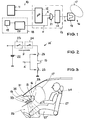
- the occupant protection system comprises an impact detection device 10 with one or more Accelerometer arrangement 11 comprising accelerometers, the output signals of which are supplied to an evaluation circuit 12, which can be a microprocessor (mP), for example, in a trigger electronics 13.
- an evaluation circuit 12 which can be a microprocessor (mP), for example, in a trigger electronics 13.
- the evaluation circuit 12 supplies an output signal A 'to an output circuit 14, which then emits a trigger signal A.
- the trigger signal A from the trigger electronics 13 is supplied to a trigger device 15 of a protective device 16 which, for example, has an airbag 17 as a means of protecting a person.
- a seat occupancy detection device 18 comprises a sensor unit 19, the output signal of which is fed to an evaluation circuit 20.
- the evaluation circuit 20 supplies an enable signal F to a gate circuit 21, via which the output signal A ′ of the evaluation circuit 12 is fed to the output circuit 14 of the trigger electronics 13 in order to generate a trigger signal A.
- the enable signal F directly to a microprocessor provided as the evaluation circuit 12 of the trigger electronics 13.
- the evaluation circuit 12 of the triggering electronics 13, the evaluation circuit 20 of the seat occupancy detection device 18 and the gate circuit 21 can, as shown in FIG. 1, by individual circuit elements, such as e.g. Microprocessors and logic circuits can be implemented, but they can also be provided together in a microprocessor of the trigger electronics 13.
- FIG. 2 shows an individual output stage 14 ′ provided in the output circuit 14 of the release electronics 13 for the release device 15, for example the squib of a gas generator for the airbag 17, in which a storage capacitor 22 via a mechanical safety switch 23, a normally closed switch 24 that can be controlled by the release signal and two trigger switches 25, controllable by the output signal A 'of the evaluation circuit 12, with which the trigger device 15 can be connected.
- the enable signal F acts directly on the correspondingly designed output stage 14 ', so that the gate circuit 21 can be dispensed with here.
- the sensor unit 19 can be installed at various locations in a motor vehicle, for. B. in the roof area. However, it is particularly advantageous if the sensor unit 19 of the seat occupancy detection device 18 - as shown in FIG. 3 - is arranged according to the invention in the area of the footwell 26 of a seat 27 to be monitored, for example below a dashboard or a glove box 28 in a vehicle.
- the sensor unit 19 comprises an optical transmitter-receiver arrangement with an optical transmitter 31 and an optical receiver 32, e.g. B. a linear CCD image sensor, and preferably a passive infrared receiver 33 which responds to the infrared radiation emitted by humans.
- the linear optical receiver 32 is arranged such that it runs essentially parallel to the front edge 27 'of the seat 27 to be monitored.
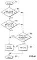
- the optical transmitter 31 transmits a monitoring signal periodically or continuously into an area lying in front of the seat 27, which is reflected on the legs of the person 27 when it is on the seat 27 to be monitored. This reflected signal is seen by the optical receiver 32 against the background of the floor of the vehicle interior. The receiver 32 generates corresponding receive signals which are processed in the evaluation circuit. The result of this evaluation is evaluated within the evaluation circuit according to FIG. 4 together with an evaluated output signal from the infrared receiver 33 in order to generate an enable signal F.
- step S2 shows, after starting an evaluation routine S1 in step S2, the first question is whether the output signal of the optical receiver 32 indicates two feet in the footwell 26. If this is the case, it is checked in step S3 whether the evaluation of the infrared signal is also positive, that is, whether a person's legs are in the footwell. If this is also the case, the monitored seat 27 is recognized as occupied and in step S4 a release signal enabling the corresponding triggering device 15 is generated. The evaluation routine is then ended (S5).
- step S6 it is checked in step S6 whether there is a single one Object is in the footwell 26, the width of which is greater than a certain width, for example about 20 cm. If this is not the case, then in step S7 the footwell 26 is rated as empty and the seat is thus not occupied.
- the release signal F assumes a value that prevents the release.
- the evaluation routine is then ended (S5).
- step S6 If an object wider than the predetermined width is recognized in step S6, it is initially assumed that these are the legs of a person lying on top of one another on the seat to be monitored. In step S3, it is then checked whether the infrared evaluation, that is to say the evaluation of the output signal of the infrared receiver, is positive, ie whether the output signal of the infrared receiver 33 also indicates the legs of a person. If this is not the case, then in step S7 the release of the assigned trigger device 15 is prevented, while in the positive case the release takes place in step S4.
- the infrared evaluation that is to say the evaluation of the output signal of the infrared receiver
- Step S6 of the evaluation routine ensures that even in the case in which a person on the seat to be monitored has crossed his legs, these can be recognized as legs in order to reliably detect the seat occupancy.
- the evaluation routine described with reference to FIG. 4 is repeated at a suitable interval for continuous or quasi-continuous monitoring of the seat occupancy. This ensures that it is reliably recognized during vehicle operation when a person on the monitored seat changes from a permitted to a prohibited sitting position and back. Accordingly, the triggerability of the associated protective device is enabled or blocked depending on the seating position of the person to be protected.
- the sensor unit 19 of the seat occupancy detection device 18 has an infrared receiver 33 in addition to the optical transmitter-receiver arrangement 31, 32, it is also possible to use the optical transmitter-receiver arrangement 31, 32 only to realize.
- step S3 in the evaluation routine according to FIG. 4 that is to say Infrared monitoring, not applicable, does not affect the safety of a person in the monitored seat.
- an acoustic, for. B. ultrasonic sensor unit 19 can be used. It is also possible to use an infrared transmitter-receiver unit in order to observe the footwell 26 of the seat to be monitored. If an infrared receiver unit which responds in particular to human heat radiation and whose output signals are suitable for image recognition is used, a particularly reliable detection of a seat occupancy can be implemented.
Abstract
Description
Die Erfindung betrifft ein Insassenschutzsystem für Fahrzeuge zur Personenbeförderung nach dem Oberbegriff des Patentanspruchs 1.The invention relates to an occupant protection system for vehicles for the transportation of passengers according to the preamble of
Derartige Insassenschutzsysteme umfassen im allgemeinen Rückhalteeinrichtungen für Personen, wie z.B. Airbags und/oder mit Gurtstraffern versehene Sicherheitsgurte, die jeweils einem bestimmten Sitz im Fahrzeug zugeordnet sind, um im Falle eines gefährlichen Unfalls zum Schutz einer auf dem jeweiligen Sitz befindlichen Person betätigt zu werden.Such occupant protection systems generally include restraints for people, e.g. Airbags and / or seat belts provided with belt tensioners, each of which is assigned to a specific seat in the vehicle in order to be actuated in the event of a dangerous accident to protect a person on the respective seat.
Während im Falle eines gefährlichen Aufpralls des Fahrzeugs die Rückhalteeinrichtungen für den Fahrer stets ausgelöst werden, ist eine Betätigung der Rückhaltevorrichtungen für den Beifahrer jedoch nur dann erforderlich, wenn der Beifahrersitz tatsächlich von einer Person belegt ist.While the restraint devices for the driver are always triggered in the event of a dangerous collision of the vehicle, actuation of the restraint devices for the front passenger is only necessary if the front passenger seat is actually occupied by one person.
Bekannte Insassenschutzsysteme sind daher bereits mit einer Sitzbelegungserkennungseinrichtung mit Fühlereinheiten ausgerüstet, die, wenn der überwachte Sitz von einer zu schützenden Person belegt ist, ein Freigabesignal an das die Rückhalteeinrichtungen betätigende Auslösegerät liefert, um die Auslösung der entsprechenden Rückhalteeinrichtungen für den belegten Sitz freizugeben.Known occupant protection systems are therefore already equipped with a seat occupancy detection device with sensor units, which, when the monitored seat is occupied by a person to be protected, delivers a release signal to the triggering device actuating the restraint devices in order to release the triggering of the corresponding restraint devices for the occupied seat.
Dabei kann eine Sitzbelegungserkennungseinrichtung beispielsweise durch eine druckempfindliche Sensormatte gebildet sein, die sich im Beifahrersitz befindet und deren Ausgangssignal ausgewertet wird, um anhand des erfaßten Gewichts oder Drucks zu entscheiden, ob sich auf dem überwachten Sitz eine Person befindet. Das Prinzip der Gewichts- oder Druckauswertung hat jedoch den Nachteil, daß eine schwere Einkaufstasche oder dergleichen, die sich auf dem überwachten Sitz befindet, nicht immer von einer echten Person unterschieden werden kann, so daß sich im Falle eines gefährlichen Aufpralls eine an sich nicht erforderliche Auslösung der Rückhalteeinrichtungen aus Sicherheitsgründen nicht immer vermeiden läßt.A seat occupancy detection device can be formed, for example, by a pressure-sensitive sensor mat which is located in the front passenger seat and whose output signal is evaluated in order to decide on the basis of the detected weight or pressure whether there is a person on the monitored seat. The principle of weight or pressure evaluation has the disadvantage, however, that a heavy shopping bag or the like, which is located on the monitored seat, cannot always be distinguished from a real person, so that, in the event of a dangerous impact, a triggering of the restraint devices which is not required per se is not always for safety reasons can be avoided.
Aus der DE 40 23 109 A1 ist bereits ein Insassenschutzsystem bekannt, dessen Sitzbelegungserkennungseinrichtung zwei mit einem akustischen oder optischen Sensor und einem geeigneten Empfänger ausgerüstete Abstandsmeßeinrichtungen aufweist, so daß nicht nur die Sitzbelegung, sondern auch die Position eines Körperteils, z.B. des Kopfes, einer auf dem Beifahrersitz befindlichen Person relativ zur Rückhalteeinrichtung festgestellt werden kann.From DE 40 23 109 A1 an occupant protection system is already known, the seat occupancy detection device of which has two distance measuring devices equipped with an acoustic or optical sensor and a suitable receiver, so that not only the seat occupancy but also the position of a body part, e.g. of the head, a person in the passenger seat can be determined relative to the restraint device.
Weiter wurde bereits vorgeschlagen, zur Sitzbelegungserkennung eine optische Bilderkennung durchzuführen. Hierfür ist eine entsprechende Sende-Empfängereinheit vorgesehen, die im Dachbereich des Fahrzeugs angeordnet ist. Die dabei zur Bilderkennung erforderliche Auswertung der Ausgangssignale der Sender-Empfängereinheit ist jedoch sehr aufwendig, da nicht nur eine auf dem Sitz befindliche Person von einem unbelebten Gegenstand, wie z.B. einer Tasche oder dergleichen, sondern auch von einem Kindersitz sicher unterschieden werden muß. Während im ersten Fall im Zweifel eine Auslösung der Rückhalteeinrichtung relativ unkritisch ist, darf im zweiten Fall, also wenn sich ein Kindersitz mit einem Kind auf dem Beifahrersitz befindet, die Auslösung der Rückhalteeinrichtung, insbesondere des Airbags, sicher ausgeschlossen sein, da es sonst zu Verletzungen des in dem Kindersitz befindlichen Kindes kommen kann.Furthermore, it has already been proposed to carry out an optical image recognition for seat occupancy detection. For this purpose, a corresponding transceiver unit is provided, which is arranged in the roof area of the vehicle. However, the evaluation of the output signals of the transmitter-receiver unit required for image recognition is very complex, since not only a person sitting on the seat is affected by an inanimate object, e.g. a bag or the like, but must also be distinguished from a child seat. While in the first case, a deployment of the restraint device is relatively uncritical, in the second case, i.e. if there is a child seat with a child in the front passenger seat, the deployment of the restraint device, in particular the airbag, can be safely ruled out, otherwise it could result in injury of the child in the child seat can come.
So weist die DE 44 33 601 C1 eine Vorrichtung zur Sitzbelegungserkennung auf, wobei die Sensoren im Kopf- oder Schalterbereich des Sitzes angeordnet sind.For example, DE 44 33 601 C1 has a device for detecting seat occupancy, the sensors being arranged in the head or switch area of the seat.
Aus der DE 44 42 841 A1 sowie der DE 40 16 610 C2 sind Vorrichtungen zum Erfassen eines Insassen eines Fahrzeugsitzes bekannt, bei der Gewichtssensoren unter anderem auch im Fußraum angeordnet sind, um die Ungenauigkeit des im Sitz befindlichen Drucksensors aufgrund unterschiedlicher Gewichtsverteilung bei unterschiedlichen Sitzpositionen zu kompensieren.From DE 44 42 841 A1 and DE 40 16 610 C2 devices for detecting an occupant of a vehicle seat are known, in which weight sensors are also arranged in the footwell, in order to reduce the inaccuracy of the pressure sensor located in the seat due to different weight distribution in different seating positions compensate.
Die DE 40 23 109 A1, die DE 38 02 159 A1 sowie die GB 22 89 332 A weisen wiederum Sensoren im Kopfbereich auf.DE 40 23 109 A1, DE 38 02 159 A1 and GB 22 89 332 A in turn have sensors in the head area.
Davon ausgehend liegt der Erfindung die Aufgabe zugrunde, ein weiteres Insassenschutzsystem der eingangs genannten Art bereitzustellen, das insbesondere eine zuverlässige Sitzbelegungserkennung auf einfache Weise ermöglicht.Based on this, the object of the invention is to provide a further occupant protection system of the type mentioned at the outset, which in particular enables reliable seat occupancy detection in a simple manner.
Diese Aufgabe wird bei einem gattungsgemäßen Insassenschutzsystem durch die kennzeichnenden Merkmale des Anspruchs 1 gelöst.This object is achieved in a generic occupant protection system by the characterizing features of
Erfindungsgemäß ist also die Fühlereinrichtung der Sitzbelegungserkennungseinrichtung so angeordnet, daß sie den Fußraum des zu überwachenden Sitzes beobachtet. Die erfindungsgemäße Ausbildung des Insassenschutzsystems hat den Vorteil, daß keine Differenzierung zwischen einer Person und einem Kindersitz erforderlich ist, da auf dem zu überwachenden Sitz befindliche Gegenstände wie Einkaufstaschen oder ähnliches ebenso unberücksichtigt bleiben, wie ein Kindersitz. Ein weiterer Vorteil besteht darin, daß auch in dem Fall eine Auslösung der Rückhalteeinrichtung, insbesondere des Airbags, verhindert wird, wenn der Beifahrer verbotenerweise seine Füße auf das Armaturenbrett legt. In diesem Fall wird der Sitz automatisch als unbelegt erkannt und damit die Auslösung des Airbags verhindert, die zu einer erheblichen Verletzung des Beifahrers führen könnte.According to the invention, the sensor device of the seat occupancy detection device is arranged so that it monitors the footwell of the seat to be monitored. The configuration of the occupant protection system according to the invention has the advantage that no differentiation between a person and a child seat is required, since objects such as shopping bags or the like located on the seat to be monitored are also disregarded as a child seat. Another advantage is that triggering of the restraint, in particular of the airbag, is prevented even if the passenger forbids his feet on the dashboard. In this case, the seat is automatically recognized as unoccupied, thus preventing the airbag from deploying, which could lead to serious injury to the front passenger.
Ein weiterer Vorteil der Erfindung besteht darin, daß die Fühlereinheit zur Überwachung des Fußraum an verschiedenen Montageorten im Kraftfahrzeug, z. B. im Dachbereich oder unterhalb des Armaturenbretts, angeordnet werden kann. Insbesondere brauchen dabei keine zu großen Anforderungen an die Einbaugenauigkeit und die Justierung der den Fußraum überwachenden Fühlereinheit gestellt zu werden, wenn die Fühlereinheit in geringerem Abstand zum zu überwachenden Bereich angeordnet ist, als bei einer Überwachung der Sitzfläche. Hinzukommt, daß auch die Auswertung der von der Fühlereinheit ausgegebenen Signale wesentlich vereinfacht ist. Insbesondere ist es bei der Auswertung der Ausgangssignale der Fühlereinheit nicht erforderlich, unterschiedliche Sitzhöhen, Sitzneigungen und Lehnenwinkel zu berücksichtigen.Another advantage of the invention is that the sensor unit for monitoring the footwell at various locations in the motor vehicle, for. B. in the roof area or below the dashboard. In particular, there is no need to make too great demands on the installation accuracy and the adjustment of the sensor unit monitoring the footwell if the sensor unit is arranged at a closer distance to the area to be monitored than when monitoring the seat surface. In addition, the evaluation of the signals output by the sensor unit is also considerably simplified. In particular, when evaluating the output signals of the sensor unit, it is not necessary to take into account different seat heights, seat inclinations and backrest angles.
Daneben besteht ein weiterer Vorteil darin, daß kein wertvoller Knotenpunkt im Fahrzeuginnenraum für die Montage benötigt wird.Another advantage is that no valuable node in the vehicle interior is required for assembly.
Bei einer besonders vorteilhaften Weiterbildung der Erfindung ist Vorgesehen, daß ein auf die Wärmestrahlung des menschlichen Körpers ansprechender Infrarotempfänger zusätzlich zu einer optischen Sender-Empfänger-Anordnung vorgesehen ist. Hierdurch läßt sich die Verwechselung von Gegenständen mit den Beinen einer auf dem zu überwachenden Sitz befindlichen Person besonders sicher ausschließen.A particularly advantageous development of the invention provides that an infrared receiver which responds to the heat radiation of the human body is provided in addition to an optical transmitter-receiver arrangement. In this way, the confusion of objects with the legs of a person located on the seat to be monitored can be particularly reliably excluded.
Weitere vorteilhafte Ausgestaltungen der Erfindung sind in den Unteransprüchen beschrieben.Further advantageous embodiments of the invention are described in the subclaims.
Die Erfindung wird im folgenden beispielsweise anhand der Zeichnung näher erläutert. In dieser zeigt:
- Fig. 1
- ein schematisches Blockschaltbild eines erfindungsgemäßen Insassenschutzsystems,
- Fig. 2
- ein vereinfachtes Schaltbild eines Ausgangsschaltkreises einer Auslöseelektronik bei einer anderen Ausgestaltung des erfindungsgemäßen Insassenschutzsystems,
- Fig. 3
- eine vereinfachte, schematische Darstellung eines Fahrzeugs zur Veranschaulichung des Einbauortes einer Fühlereinheit einer Sitzbelegungserkennungseinrichtung für ein erfindungsgemäßes Insassenschutzsystem und
- Fig. 4
- ein Flußdiagramm der Auswertung der Ausgangssignale der Fühlereinheit.
- Fig. 1
- 1 shows a schematic block diagram of an occupant protection system according to the invention,
- Fig. 2
- 1 shows a simplified circuit diagram of an output circuit of a trigger electronics in another configuration of the occupant protection system according to the invention,
- Fig. 3
- a simplified, schematic representation of a vehicle to illustrate the installation location of a sensor unit of a seat occupancy detection device for an occupant protection system according to the invention and
- Fig. 4
- a flow chart of the evaluation of the output signals of the sensor unit.
In den verschiedenen Figuren der Zeichnung sind einander entsprechende Teile mit gleichen Bezugszeichen versehen.Corresponding parts in the various figures of the drawing are provided with the same reference symbols.
Das erfindungsgemäße Insassenschutzsystem umfaßt, wie Figur 1 zeigt, eine Aufprallerkennungseinrichtung 10 mit einer einen oder mehrere Beschleunigungsaufnehmer umfassenden Beschleunigungsaufnehmeranordnung 11, deren Ausgangssignale an eine Auswerteschaltung 12, die beipielsweise ein Mikroprozessor (mP) sein kann, in einer Auslöseelektronik 13 geliefert werden. Die Auswerteschaltung 12 liefert im Falle eines gefährlichen Aufpralls ein Ausgangssignal A' an einen Ausgangsschaltkreis 14, der daraufhin ein Auslösesignal A abgibt. Das Auslösesignal A von der Auslöseelektronik 13 wird an eine Auslöseeinrichtung 15 einer Schutzeinrichtung 16 geliefert, die z.B. einen Airbag 17 als ein eine Person schützendes Mittel aufweist.As shown in FIG. 1, the occupant protection system according to the invention comprises an
Eine Sitzbelegungserkennungseinrichtung 18 umfaßt eine Fühlereinheit 19, deren Ausgangssignal einer Auswerteschaltung 20 zugeführt ist. Die Auswerteschaltung 20 liefert im dargestellten Ausführungsbeispiel ein Freigabesignal F an eine Torschaltung 21, über die das Ausgangssignal A' der Auswerteschaltung 12 zur Erzeugung eines Auslösesignals A an den Ausgangsschaltkreis 14 der Auslöseelektronik 13 geführt wird. Es ist jedoch auch möglich, das Freigabesignal F direkt einem als Auswerteschaltung 12 der Auslöseelektronik 13 vorgesehenen Mikroprozessor zuzuführen.A seat
Die Auswerteschaltung 12 der Auslöseelektronik 13, die Auswerteschaltung 20 der Sitzbelegungserkennungseinrichtung 18 und die Torschaltung 21 können, wie in Figur 1 dargestellt, durch einzelne Schaltungselemente, wie z.B. Mikroprozessoren und Logikschaltkreise realisiert werden, sie können aber auch in einem Mikroprozessor der Auslöseelektronik 13 gemeinsam vorgesehen sein.The
Figur 2 zeigt eine einzelne im Ausgangsschaltkreis 14 der Auslöseelektronik 13 vorgesehene Ausgangsstufe 14' für die Auslöseeinrichtung 15, z.B. die Zündpille eines Gasgenerators für den Airbag 17, in der ein Speicherkondensator 22 über einen mechanischen Sicherheitsschalter 23, einen vom Freigabesignal steuerbaren, normalerweise geschlossenen Schalter 24 und zwei vom Ausgangssignal A' der Auswerteschaltung 12 steuerbare Auslöseschalter 25, mit der Auslöseeinrichtung 15 verbindbar ist. Bei der Ausgestaltung nach Figur 2 wirkt das Freigabesignal F unmittelbar auf die entsprechend ausgelegte Ausgangsstufe 14' ein, so daß hierbei auf die Torschaltung 21 verzichtet werden kann.FIG. 2 shows an
Die Fühlereinheit 19 läßt sich an verschiedenen Montageorten in einem Kraftfahrzeug, z. B. im Dachbereich, anordnen. Besonders vorteilhaft ist es jedoch, wenn die Fühlereinheit 19 der Sitzbelegungserkennungseinrichtung 18 - wie in Figur 3 dargestellt - erfindungsgemäß im Bereich des Fußraums 26 eines zu überwachenden Sitzes 27 beispielsweise unterhalb eines Armaturenbretts oder eines Handschuhfachs 28 in einem Fahrzeug angeordnet ist. Die Fühlereinheit 19 umfaßt eine optische Sender-Empfänger-Anordnung mit einem optischen Sender 31 und einem optischen Empfänger 32, z. B. einen linienförmigen CCD-Bildsensor, sowie vorzugsweise einen passiven Infrarotempfänger 33, der auf die vom Menschen ausgesandte Infrarotstrahlung anspricht. Der linienförmige optische Empfänger 32 ist dabei so angeordnet, daß er im wesentlichen parallel zur Sitzvorderkante 27' des zu überwachenden Sitzes 27 verläuft.The
Zur Überwachung des Fußraums 26 sendet der optische Sender 31 periodisch oder kontinuierlich ein Überwachungssignal in einen vor dem Sitz 27 liegenden Bereich aus, das, wenn sich eine Person 34 auf dem zu überwachenden Sitz 27 befindet, an deren Beinen reflektiert wird. Dieses reflektierte Signal wird vom optischen Empfänger 32 vor dem Hintergrund des Bodens des Fahrzeuginnenraums gesehen. Der Empfänger 32 erzeugt entsprechende Empfangssignale, die in der Auswerteschaltung verarbeitet werden. Das Ergebnis dieser Auswertung wird innerhalb der Auswerteschaltung entsprechend Figur 4 gemeinsam mit einem bewerteten Ausgangssignal des Infrarotempfängers 33 zur Erzeugung eines Freigabesignals F bewertet.To monitor the
Wie Figur 4 zeigt, wird nach dem Start S1 einer Bewertungsroutine im Schritt S2 zunächst gefragt, ob das Ausgangssignal des optischen Empfängers 32 zwei Füße im Fußraum 26 anzeigt. Ist dies der Fall, wird im Schritt S3 überprüft, ob die Auswertung des Infrarotsignals ebenfalls positiv ist, ob sich also die Beine eines Menschen im Fußraum befinden. Ist dies ebenfalls der Fall, so wird der überwachte Sitz 27 als belegt erkannt und im Schritt S4 wird ein die entsprechende Auslöseeinrichtung 15 freigebendes Freigabesignal erzeugt. Damit ist die Bewertungsroutine beendet (S5).As FIG. 4 shows, after starting an evaluation routine S1 in step S2, the first question is whether the output signal of the
Wird jedoch im Schritt S2 festgestellt, daß sich im Fußraum keine zwei Füße oder Beine befinden, so wird im Schritt S6 überprüft, ob sich ein einzelner Gegenstand im Fußraum 26 befindet, dessen Breite größer als eine bestimmte Breite, z.B. etwa 20 cm, ist. Ist dies nicht der Fall, so wird in Schritt S7 der Fußraum 26 als leer und damit der Sitz als nicht belegt bewertet. Das Freigabesignal F nimmt einen wert an, der die Freigabe verhindert. Daraufhin wird die Bewertungsroutine beendet (S5).However, if it is determined in step S2 that there are no two feet or legs in the footwell, then it is checked in step S6 whether there is a single one Object is in the
Wird im Schritt S6 ein Gegenstand breiter als die vorgegebene Breite erkannt, so wird zunächst angenommen, daß es sich hierbei um die übereinander geschlagenen Beine einer auf dem zu überwachenden Sitz befindlichen Person handelt. Im Schritt S3 wird daraufhin überprüft, ob die Infrarotauswertung, also die Auswertung des Ausgangssignals des Infrarotempfängers positiv ist, ob also auch das Ausgangssignal des Infrarotempfängers 33 die Beine einer Person anzeigt. Ist dies nicht der Fall, so wird anschließend im Schritt S7 die Freigabe der zugeordneten Auslöseeinrichtung 15 verhindert, während im positiven Fall die Freigabe im Schritt S4 erfolgt.If an object wider than the predetermined width is recognized in step S6, it is initially assumed that these are the legs of a person lying on top of one another on the seat to be monitored. In step S3, it is then checked whether the infrared evaluation, that is to say the evaluation of the output signal of the infrared receiver, is positive, ie whether the output signal of the
Durch den Schritt S6 der Bewertungsroutine wird sichergestellt, daß auch in dem Fall, in dem eine auf dem zu überwachenden Sitz befindliche Person ihre Beine übereinander geschlagen hat, diese als Beine erkannt werden können, um die Sitzbelegung sicher zu erfassen.Step S6 of the evaluation routine ensures that even in the case in which a person on the seat to be monitored has crossed his legs, these can be recognized as legs in order to reliably detect the seat occupancy.
Die anhand von Figur 4 beschriebene Bewertungsroutine wird zu einer kontinuierlichen oder quasi-kontinuierlichen Überwachung der Sitzbelegung in geeigneten Abständen wiederholt. Hierdurch wird gewährleistet, daß während des Fahrzeugbetriebs sicher erkannt wird, wenn eine auf dem überwachten Sitz befindliche Person aus einer erlaubten in eine verbotene Sitzposition und zurück wechselt. Dementsprechend wird die Auslösbarkeit der zugeordneten Schutzeinrichtung in Abhängigkeit von der Sitzposition der zu schützenden Person freigegeben oder gesperrt.The evaluation routine described with reference to FIG. 4 is repeated at a suitable interval for continuous or quasi-continuous monitoring of the seat occupancy. This ensures that it is reliably recognized during vehicle operation when a person on the monitored seat changes from a permitted to a prohibited sitting position and back. Accordingly, the triggerability of the associated protective device is enabled or blocked depending on the seating position of the person to be protected.
Obwohl bei dem beschriebenen, bevorzugten Ausführungsbeispiel der Erfindung die Fühlereinheit 19 der Sitzbelegungserkennungseinrichtung 18 neben der optischen Sender-Empfänger-Anordnung 31, 32 einen Infrarotempfänger 33 aufweist, ist es auch möglich, die Erfindung nur mit der optischen Sender-Empfänger-Anordnung 31, 32 zu realisieren. Obwohl in diesem Fall der Schritt S3 in der Bewertungsroutine nach Fig. 4, also die Infrarotüberwachung, entfällt, wird die Sicherheit einer auf dem überwachten Sitz befindlichen Person nicht beeinträchtigt.Although in the described preferred embodiment of the invention the
Anstelle der beschriebenen optischen Sender-Empfänger-Anordnung 31, 32 kann bei dem erfindungsgemäßen Insassenschutzsystem auch eine akustische, z. B. mit Ultraschall arbeitende Fühlereinheit 19 eingesetzt werden. Weiter ist es möglich, eine Infrarotsender-Empfängereinheit einzusetzen, um den Fußraum 26 des zu überwachenden Sitzes zu beobachten. Wenn eine insbesondere auf die menschliche Wärmestrahlung ansprechende Infrarotempfängereinheit eingesetzt wird, deren Ausgangssignale für eine Bilderkennung geeignet sind, ist eine besonders sichere Erkennung einer Sitzbelegung realisierbar.Instead of the optical transmitter-
Claims (7)
daß mindestens eine der Fühlereinheiten (19) als optische Sender-Empfänger-Anordnung (31, 32) ausgestaltet und auf den Fußraum gerichtet ist.Occupant protection system for vehicles for passenger transportation,
that at least one of the sensor units (19) is designed as an optical transmitter-receiver arrangement (31, 32) and is directed towards the footwell.
Applications Claiming Priority (2)
| Application Number | Priority Date | Filing Date | Title |
|---|---|---|---|
| DE1996111073 DE19611073B4 (en) | 1996-03-21 | 1996-03-21 | Occupant protection system for vehicles for the transportation of passengers |
| DE19611073 | 1996-03-21 |
Publications (2)
| Publication Number | Publication Date |
|---|---|
| EP0796773A2 true EP0796773A2 (en) | 1997-09-24 |
| EP0796773A3 EP0796773A3 (en) | 1997-12-29 |
Family
ID=7788925
Family Applications (1)
| Application Number | Title | Priority Date | Filing Date |
|---|---|---|---|
| EP97104469A Withdrawn EP0796773A3 (en) | 1996-03-21 | 1997-03-15 | Occupant protection system for passenger transport vehicles |
Country Status (2)
| Country | Link |
|---|---|
| EP (1) | EP0796773A3 (en) |
| DE (1) | DE19611073B4 (en) |
Families Citing this family (13)
| Publication number | Priority date | Publication date | Assignee | Title |
|---|---|---|---|---|
| DE19812830B4 (en) * | 1998-03-24 | 2006-07-20 | Volkswagen Ag | Method and device for triggering an airbag with seat position detection |
| DE19909403B4 (en) | 1999-03-05 | 2004-08-26 | Conti Temic Microelectronic Gmbh | Method for controlling an occupant protection system |
| DE10026383B4 (en) * | 1999-07-14 | 2011-03-10 | Volkswagen Ag | Method and device for detecting the position of an object, in particular a vehicle occupant, on a seat in a motor vehicle |
| DE10106732B4 (en) * | 2000-02-29 | 2006-02-23 | Conti Temic Microelectronic Gmbh | Method for operating an occupant protection system |
| DE10144689B4 (en) * | 2001-09-11 | 2010-04-08 | Volkswagen Ag | Method and device for detecting objects |
| DE10235881B4 (en) * | 2002-08-06 | 2007-02-22 | Daimlerchrysler Ag | Occupant detection system in a motor vehicle |
| DE102006019720A1 (en) * | 2006-04-27 | 2007-10-31 | Siemens Ag | Safety arrangement for e.g. motor vehicle, has sensor device detecting allocation of transportation area, and control unit locking door of area e.g. rear seat, based on detected allocation of area of vehicle |
| DE102009016052B4 (en) | 2009-04-02 | 2018-09-27 | Bayerische Motoren Werke Aktiengesellschaft | Device for detecting an exit movement of a vehicle user |
| DE102014117794A1 (en) * | 2014-12-03 | 2016-06-09 | Valeo Schalter Und Sensoren Gmbh | Device for detecting an object in an interior of a motor vehicle, motor vehicle and associated method |
| US9604588B1 (en) * | 2015-11-25 | 2017-03-28 | Ford Global Technologies, Llc | Rear row knee bolster deployment control |
| US9744929B2 (en) * | 2015-11-25 | 2017-08-29 | Ford Global Technologies, Llc | Front passenger knee bolster deployment control |
| US10137802B2 (en) | 2016-03-11 | 2018-11-27 | Ford Global Technologies, Llc | Detecting occupant presence on a vehicle seat |
| US20190322233A1 (en) * | 2018-04-24 | 2019-10-24 | Ford Global Technologies, Llc | Controlling Airbag Activation Status At A Motor Vehicle |
Citations (6)
| Publication number | Priority date | Publication date | Assignee | Title |
|---|---|---|---|---|
| US4951963A (en) * | 1989-10-02 | 1990-08-28 | Automotive Systems Laboratory, Inc. | Self-adjusting knee bolster |
| EP0473324A1 (en) * | 1990-08-27 | 1992-03-04 | Automotive Systems Laboratory Inc. | Restraint system with passenger out-of-position sensor for vehicles |
| WO1995018028A1 (en) * | 1993-12-29 | 1995-07-06 | Sensor Technology Co., Ltd. | Operation judgement system for an occupant protection device for a front passenger seat |
| DE4406906A1 (en) * | 1994-03-03 | 1995-09-07 | Docter Optik Wetzlar Gmbh | Inside room monitoring device |
| WO1995027635A1 (en) * | 1994-04-12 | 1995-10-19 | Aerojet General Corporation | Automotive occupant sensor system and method of operation by sensor fusion |
| EP0734921A2 (en) * | 1995-03-31 | 1996-10-02 | Toyota Jidosha Kabushiki Kaisha | Air bag apparatus for passenger seat |
Family Cites Families (9)
| Publication number | Priority date | Publication date | Assignee | Title |
|---|---|---|---|---|
| DE3802159C2 (en) * | 1988-01-26 | 1996-09-05 | Porsche Ag | Seat occupancy detection device |
| DE4016610A1 (en) * | 1990-05-23 | 1991-11-28 | Audi Ag | SAFETY DEVICE ON A MOTOR VEHICLE WITH AN INFLATABLE GAS PILLOW |
| DE4042722C2 (en) * | 1990-07-20 | 2002-11-21 | Conti Temic Microelectronic | Procedure for triggering occupant protection devices |
| US5573269A (en) * | 1993-12-02 | 1996-11-12 | Trw Vehicle Safety Systems Inc. | Apparatus and method for sensing and restraining an occupant of a vehicle seat |
| JP3044518B2 (en) * | 1993-12-13 | 2000-05-22 | 株式会社イナックス | Human body detection device |
| DE4409971C2 (en) * | 1994-03-23 | 1996-01-18 | Daimler Benz Ag | Device for recognizing a child seat strapped to the front passenger seat of a motor vehicle |
| JP2876387B2 (en) * | 1994-04-28 | 1999-03-31 | 小糸工業株式会社 | Seating detection device |
| GB2289332B (en) * | 1994-05-09 | 1999-01-06 | Automotive Tech Int | Vehicle interior identification and monitoring system |
| DE4433601C1 (en) * | 1994-09-21 | 1996-04-04 | Kurt Bruse | Activation device for vehicle passengers safety systems |
-
1996
- 1996-03-21 DE DE1996111073 patent/DE19611073B4/en not_active Expired - Fee Related
-
1997
- 1997-03-15 EP EP97104469A patent/EP0796773A3/en not_active Withdrawn
Patent Citations (6)
| Publication number | Priority date | Publication date | Assignee | Title |
|---|---|---|---|---|
| US4951963A (en) * | 1989-10-02 | 1990-08-28 | Automotive Systems Laboratory, Inc. | Self-adjusting knee bolster |
| EP0473324A1 (en) * | 1990-08-27 | 1992-03-04 | Automotive Systems Laboratory Inc. | Restraint system with passenger out-of-position sensor for vehicles |
| WO1995018028A1 (en) * | 1993-12-29 | 1995-07-06 | Sensor Technology Co., Ltd. | Operation judgement system for an occupant protection device for a front passenger seat |
| DE4406906A1 (en) * | 1994-03-03 | 1995-09-07 | Docter Optik Wetzlar Gmbh | Inside room monitoring device |
| WO1995027635A1 (en) * | 1994-04-12 | 1995-10-19 | Aerojet General Corporation | Automotive occupant sensor system and method of operation by sensor fusion |
| EP0734921A2 (en) * | 1995-03-31 | 1996-10-02 | Toyota Jidosha Kabushiki Kaisha | Air bag apparatus for passenger seat |
Also Published As
| Publication number | Publication date |
|---|---|
| DE19611073B4 (en) | 2004-04-15 |
| EP0796773A3 (en) | 1997-12-29 |
| DE19611073A1 (en) | 1997-09-25 |
Similar Documents
| Publication | Publication Date | Title |
|---|---|---|
| DE69935803T2 (en) | SEAT OCCUPANCY DETECTION | |
| DE69928789T2 (en) | DETECTOR FOR VEHICLE INITIALS | |
| DE4005598C2 (en) | Protection procedure for vehicle occupants and device for carrying out the procedure | |
| DE69924246T2 (en) | SEAT OCCUPANCY DETECTION | |
| DE69820869T2 (en) | AIR BAG CONTROL SYSTEM AND METHOD | |
| DE102015210438B4 (en) | Method and system for protecting occupants in a vehicle | |
| DE19637108B4 (en) | Occupant protection system for motor vehicles and a method for continuously monitoring the seating position of the occupant | |
| DE69932045T2 (en) | SEAT OCCUPANCY DETECTION | |
| DE4433601C1 (en) | Activation device for vehicle passengers safety systems | |
| DE10060649B4 (en) | System and method for controlling a vehicle occupant protection device | |
| DE10345726B4 (en) | A restraint system for restraining an occupant in a motor vehicle and method for dynamically controlling such a restraint system | |
| DE4426090C2 (en) | Devices for protecting vehicle occupants and the body in a motor vehicle | |
| DE10215386B4 (en) | A method and apparatus for controlling an actuatable restraint that uses switched thresholds based on lateral acceleration | |
| DE10123921C1 (en) | Occupant restraint system with a belt force limiting device | |
| EP2607180B1 (en) | Method for the determination of the weight of at least one occupant of a vehicle | |
| DE19930384B4 (en) | Protection device for vehicle occupants | |
| DE102006021824B4 (en) | Method and apparatus for controlling an actuatable restraint using XY side satellite accelerometers | |
| DE19814678B4 (en) | Airbag control system for passenger seats | |
| DE10215384B4 (en) | A method and apparatus for controlling an actuatable restraint that uses switched thresholds based on crush zone sensors | |
| EP1136327A2 (en) | Vehicle occupant position sensor | |
| DE19611073B4 (en) | Occupant protection system for vehicles for the transportation of passengers | |
| DE102006024977A1 (en) | A method and apparatus for controlling a front actuatable restraint device using lateral satellite containment sensors | |
| DE102017011827A1 (en) | Method for operating an occupant protection device | |
| WO2017220331A1 (en) | System and method for passenger compartment detection in a vehicle | |
| EP1012007B1 (en) | Device for protecting occupants in an automobile and a method for controlling the inflation of a bag in an automobile |
Legal Events
| Date | Code | Title | Description |
|---|---|---|---|
| PUAI | Public reference made under article 153(3) epc to a published international application that has entered the european phase |
Free format text: ORIGINAL CODE: 0009012 |
|
| AK | Designated contracting states |
Kind code of ref document: A2 Designated state(s): DE ES FR GB IT SE |
|
| PUAL | Search report despatched |
Free format text: ORIGINAL CODE: 0009013 |
|
| AK | Designated contracting states |
Kind code of ref document: A3 Designated state(s): DE ES FR GB IT SE |
|
| STAA | Information on the status of an ep patent application or granted ep patent |
Free format text: STATUS: THE APPLICATION IS DEEMED TO BE WITHDRAWN |
|
| 18D | Application deemed to be withdrawn |
Effective date: 19980630 |