EP0797272A1 - Process and device for securing a wire bundle to a telephone or data terminal block - Google Patents
Process and device for securing a wire bundle to a telephone or data terminal block Download PDFInfo
- Publication number
- EP0797272A1 EP0797272A1 EP97420045A EP97420045A EP0797272A1 EP 0797272 A1 EP0797272 A1 EP 0797272A1 EP 97420045 A EP97420045 A EP 97420045A EP 97420045 A EP97420045 A EP 97420045A EP 0797272 A1 EP0797272 A1 EP 0797272A1
- Authority
- EP
- European Patent Office
- Prior art keywords
- strip
- plug
- arm
- hook
- patch cord
- Prior art date
- Legal status (The legal status is an assumption and is not a legal conclusion. Google has not performed a legal analysis and makes no representation as to the accuracy of the status listed.)
- Granted
Links
Images


Classifications
-
- H—ELECTRICITY
- H01—ELECTRIC ELEMENTS
- H01R—ELECTRICALLY-CONDUCTIVE CONNECTIONS; STRUCTURAL ASSOCIATIONS OF A PLURALITY OF MUTUALLY-INSULATED ELECTRICAL CONNECTING ELEMENTS; COUPLING DEVICES; CURRENT COLLECTORS
- H01R13/00—Details of coupling devices of the kinds covered by groups H01R12/70 or H01R24/00 - H01R33/00
- H01R13/62—Means for facilitating engagement or disengagement of coupling parts or for holding them in engagement
- H01R13/627—Snap or like fastening
- H01R13/6275—Latching arms not integral with the housing
Definitions
- the present invention relates to a method and to a device for the secure connection of a patch cord on a strip for interconnection of telephone or computer lines.
- a telephone or computer installation can include a very large number of strips on the same chassis, these strips being very close to one another. We are then in the presence of a real forest of patch cords which are tight against each other. If each patch cord is simply plugged into its strip, it may happen that by handling it, the operator accidentally disconnects one or more other neighboring patch cords, and then does not know where to reconnect these. It can also happen that it only partially dislocates one or more neighboring cords, and that it then does not notice it, so that one or more lines then remain disconnected without being aware of it.
- connection plug of a patch cord called "push-pull”
- push-pull which is provided on the one hand with a locking piece which surrounds this connection plug and which comprises several elastic arms with hooks which come to be plugged into natural interstices of the strip, and on the other hand an unlocking part movable axially with respect to said locking piece, which surrounds the latter and which cooperates with it to undo the snap-fastening of the elastic arms with hooks on the strip when it is pulled axially on this unlocking part.
- This known secure connection device does not require any modification of the strip.
- its unlocking which requires grasping the unlocking piece between two fingers, to pull it backwards, becomes practically impossible, without using a specially adapted tool, when one is in the presence of a forest of cords of brewing tightly against each other because there is not enough room to pass the fingers.
- such a device is quite complex and therefore expensive to produce.
- this additional cavity is formed in the insulating space which separates, on this large face of the strip, two insulation displacement contacts of the same pair.
- this additional cavity is formed in the insulating space which separates, on this large face of the strip, two insulation displacement contacts of the same pair.
- the reference 1 designates a portion of the plastic body of a strip for interconnection of telephone or computer lines, for example a strip as described in document EP-A-0.524 .115 cited above. More specifically, a front portion of the strip is shown here which includes the connection relating to a single pair, that is to say in fact a first pair of contacts 2, 3 on the large upper face 4 of the strip and another pair of contacts 5, 6 on the large underside of the strip, these two pairs being for example interconnected, by an elastic connection, inside the strip.
- the arm 12 swings around a metal axis 16 which is positioned transversely in the upper part 17 of the plastic body of the connection plug 8, approximately halfway along the arm 12.
- a groove 20 is provided in this upper part 17 of the plastic body of the plug to allow free passage to the arm 12.
- the pin 19 crashes and resiliently pushes arm 12 as if to make it tilt back forward.
- a slight elastic deformation (not visible in the drawing) of this arm also creates an elastic repulsion effect towards the front when the rear part 18 is pressed against the resistance due to the stop. 19.
- the plug 8 could include several pairs instead of one and the arm 12 could be made of any other rigid or semi-rigid material, for example metal.
- the strip 1 is designed to receive several patch cords 7, each provided with a connector 8, so that in reality the face 4 has several cavities 9, preferably one cavity 9 per pair 2, 3.
- all or part of these cavities 9 could be provided on the other large face of the strip, to the counterpart of the location shown in Figure 1 for the face 4 and then the corresponding locking arms or paddles 12 would be provided accordingly at the bottom of connector 8.
Abstract
Description
La présente invention se rapporte à un procédé et à un dispositif de connexion sécurisée d'un cordon de brassage sur une réglette d'interconnexion de lignes téléphoniques ou informatiques.The present invention relates to a method and to a device for the secure connection of a patch cord on a strip for interconnection of telephone or computer lines.
Il est connu d'interconnecter deux réglettes entre elles à l'aide d'un ou plusieurs « cordons de brassage » Le document EP-A-0.524.115 de la Société Demanderesse décrit, entre autres, comment on réalise, par une fiche de connexion appropriée, le branchement d'un tel cordon sur une réglette. Ces cordons de brassage sont par ailleurs nécessaires lorsque l'on travaille avec des lignes à haut débit, soit pour connecter une ou plusieurs lignes sur un appareil électrique, soit pour connecter des lignes entre elles.It is known to interconnect two strips with one another using one or more “patch cords”. Document EP-A-0.524.115 from the Applicant Company describes, among other things, how a plug is made appropriate connection, the connection of such a cord to a strip. These patch cords are also necessary when working with high speed lines, either to connect one or more lines to an electrical device, or to connect lines between them.
Une installation téléphonique ou informatique peut comporter un très grand nombre de réglettes sur un même châssis, ces réglettes étant très rapprochées l'une de l'autre. On est alors en présence d'une véritable forêt de cordons de brassage qui sont serrés l'un contre l'autre. Si chaque cordon de brassage est simplement enfiché sur sa réglette, il peut arriver qu'en le manipulant, l'opérateur débranche accidentellement un ou plusieurs autres cordons de brassage voisins, et ne sache alors plus où rebrancher ceux-ci. Il peut aussi arriver qu'il ne déboîte que partiellement un ou plusieurs cordons voisins, et qu'il ne s'en aperçoive alors pas, de sorte qu'une ou plusieurs lignes restent alors débranchées sans qu'on le sache.A telephone or computer installation can include a very large number of strips on the same chassis, these strips being very close to one another. We are then in the presence of a real forest of patch cords which are tight against each other. If each patch cord is simply plugged into its strip, it may happen that by handling it, the operator accidentally disconnects one or more other neighboring patch cords, and then does not know where to reconnect these. It can also happen that it only partially dislocates one or more neighboring cords, and that it then does not notice it, so that one or more lines then remain disconnected without being aware of it.
Le document FR-A-2.698.511 décrit à ce propos une fiche de connexion d'un cordon de brassage, dite « push-pull », qui est munie d'une part d'une pièce de verrouillage qui entoure cette fiche de connexion et qui comporte plusieurs bras élastiques à crochets qui viennent s'enficher dans des interstices naturels de la réglette, et d'autre part d'une pièce de déverrouillage mobile axialement par rapport à ladite pièce de verrouillage, qui entoure cette dernière et qui coopère avec elle pour défaire l'encliquetage des bras élastiques à crochets sur la réglette lorsqu'on tire axialement sur cette pièce de déverrouillage.The document FR-A-2,698,511 describes in this connection a connection plug of a patch cord, called "push-pull", which is provided on the one hand with a locking piece which surrounds this connection plug and which comprises several elastic arms with hooks which come to be plugged into natural interstices of the strip, and on the other hand an unlocking part movable axially with respect to said locking piece, which surrounds the latter and which cooperates with it to undo the snap-fastening of the elastic arms with hooks on the strip when it is pulled axially on this unlocking part.
Ce dispositif de connexion sécurisée connu ne nécessite aucune modification de la réglette. En revanche, son déverrouillage, qui nécessite de saisir entre deux doigts la pièce de déverrouillage, pour la tirer vers l'arrière, devient pratiquement impossible, sans utiliser un outil spécialement adapté, lorsqu'on est en présence d'un forêt de cordons de brassage serrés l'un contre l'autre car la place n'est pas suffisante pour passer les doigts. En outre, un tel dispositif est de réalisation assez complexe et donc onéreuse.This known secure connection device does not require any modification of the strip. On the other hand, its unlocking, which requires grasping the unlocking piece between two fingers, to pull it backwards, becomes practically impossible, without using a specially adapted tool, when one is in the presence of a forest of cords of brewing tightly against each other because there is not enough room to pass the fingers. In addition, such a device is quite complex and therefore expensive to produce.
L'invention vise à remédier à ces inconvénients. Elle se rapporte à cet effet à un procédé et à un dispositif pour réaliser, de manière sécurisée, la connexion de la fiche d'extrémité d'un cordon de brassage sur une réglette réceptrice, ce procédé consistant :
- d'une part à ménager, dans la partie isolante d'au moins une des deux grandes faces de la réglette, dans l'espace isolant qui sépare, sur cette grande face de la réglette, deux contacts autodénudants d'une même paire et sensiblement au niveau de la rangée correspondante de contacts de connexion autodénudante, au moins une cavité additionnelle
- et d'autre part à équiper cette fiche de connexion du cordon de brassage d'un bras, longiligne et basculant, de verrouillage dont une extrémité libre porte un crochet qui vient, par effet de rappel élastique de basculement, s'encliqueter, avec effet de verrouillage, dans ladite cavité lorsque cette fiche est installée en position sur la réglette, et dont l'autre extrémité libre est positionnée à l'arrière de cette fiche et constitue un levier de déverrouillage, par basculement forcé, de ce bras de verrouillage.
- on the one hand, in the insulating part of at least one of the two large faces of the strip, in the insulating space which separates, on this large face of the strip, two insulating contacts of the same pair and substantially at the level of the corresponding row of insulation displacement connection contacts, at least one additional cavity
- and on the other hand to equip this connection plug of the patch cord with a long, tilting arm, of locking, of which a free end carries a hook which comes, by elastic tilting return effect, to snap in, with effect locking, in said cavity when this plug is installed in position on the strip, and the other free end of which is positioned at the rear of this plug and constitutes an unlocking lever, by forced tilting, of this locking arm.
Avantageusement, cette cavité additionnelle est ménagée dans l'espace isolant qui sépare, sur cette grande face de la réglette, deux contacts autodénudants d'une même paire.Advantageously, this additional cavity is formed in the insulating space which separates, on this large face of the strip, two insulation displacement contacts of the same pair.
Avantageusement, cette cavité additionnelle est ménagée dans l'espace isolant qui sépare, sur cette grande face de la réglette, deux contacts autodénudants d'une même paire.Advantageously, this additional cavity is formed in the insulating space which separates, on this large face of the strip, two insulation displacement contacts of the same pair.
De toute façon, l'invention sera bien comprise, et ses divers avantages et caractéristiques ressortiront mieux, lors de la description suivante d'un exemple non limitatif de réalisation, en référence au dessin schématique annexé dans lequel :
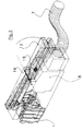
- Figure 1 est une vue en perspective partiellement éclatée d'un dispositif conforme à l'invention, de connexion sécurisée d'un cordon de brassage sur une réglette.
- Figure 2 montre ce cordon de brassage connecté, de manière sécurisée, sur cette réglette.
- Figure 3, 4, 5 sont respectivement une vue latérale, une vue de dessus et une vue en bout par l'arrière, de la connexion sécurisée selon Figure 2.
- Figure 1 is a partially exploded perspective view of a device according to the invention, for secure connection of a patch cord on a strip.
- Figure 2 shows this patch cord connected securely to this strip.
- Figure 3, 4, 5 are respectively a side view, a top view and an end view from the rear, of the secure connection according to Figure 2.
En se référant à l'ensemble des figures 1 à 5, la référence 1 désigne une portion du corps plastique d'une réglette d'interconnexion de lignes téléphoniques ou informatiques, par exemple une réglette telle que décrite dans le document EP-A-0.524.115 précité. Plus précisément, il est ici représenté une portion avant de la réglette qui inclut la connectique relative à une seule paire, c'est-à-dire en fait une première paire de contacts 2, 3 sur la grande face supérieure 4 de la réglette et une autre paire de contacts 5, 6 sur la grande face inférieure de la réglette, ces deux paires étant par exemple interconnectées, par une liaison élastique, à l'intérieur de la réglette.Referring to all of FIGS. 1 to 5, the
Comme il est décrit plus en détails dans le document EP-A-0.524. 115, il est possible d'enficher, sur la portion 1 seule ou sur plusieurs portions adjacentes, un cordon de brassage 7 pour relier les contacts de ligne 2, 3, 5, 6 soit à une autre réglette, soit à un appareil électronique. Ce cordon de brassage est muni en conséquence d'une fiche d'extrémité, ou connecteur, qui vient s'enficher sur la ou les portions de réglette 1 considérées.As described in more detail in document EP-A-0.524. 115, it is possible to insert, on the
Conformément à l'invention et pour éviter que la fiche 8 ne se désemboîte accidentellement, deux dispositions concomitantes sont prévues :
- Une
petite cavité 9, de section rectangulaire, est ménagée sur la grande face supérieure 4 du corps plastique de la réglette. Cette cavité est positionnée légèrement en retrait de la face avant 10 de la réglette, c'est-à-dire sensiblement au niveau de la partie avant de la rangée correspondante de contacts de connexion autodénudante. Elle est ici ménagée au milieu de laportion 1 qui englobe lespaires 2, 3 - 5, 6 enfourchées par leconnecteur 8 et dans l'espace isolant 11 qui sépare, sur cettegrande face 4 de la réglette, les deux contacts autodénudants de la paire supérieure 2, 3. - Le connecteur, ou fiche de connexion, 8 du cordon de
brassage 7 est équipé d'un bras basculant 12, d'axe parallèle à celui de ceconnecteur 8. Cebras 12 est réalisé en matière plastique semi-rigide, et son extrémité libre avant 13 est positionnée légèrement en arrière de la face d'embouchure 15 duconnecteur 8 et porte un crochet 14 de verrouillage par encliquetage dans lacavité 9 précitée.
- A
small cavity 9, of rectangular section, is formed on the largeupper face 4 of the plastic body of the strip. This cavity is positioned slightly behind thefront face 10 of the strip, that is to say substantially at the level of the front part of the corresponding row of insulation displacement connection contacts. It is here provided in the middle of theportion 1 which includes thepairs 2, 3 - 5, 6 straddled by theconnector 8 and in theinsulating space 11 which separates, on thislarge face 4 of the strip, the two insulation displacement contacts of theupper pair - The connector, or connection plug, 8 of the
patch cord 7 is equipped with a tiltingarm 12, with an axis parallel to that of thisconnector 8. Thisarm 12 is made of semi-rigid plastic, and itsfree end front 13 is positioned slightly behind themouth face 15 of theconnector 8 and carries a hook 14 for snap locking in theaforementioned cavity 9.
Le bras 12 bascule autour d'un axe métallique 16 qui est positionné transversalement dans la partie supérieure 17 du corps plastique de la fiche de connexion 8, environ à mi-longueur du bras 12. Une saignée 20 est prévue dans cette partie supérieure 17 du corps plastique de la fiche pour laisser libre passage au bras 12.The
L'extrémité arrière 18 de ce bras basculant 12 arrive à l'arrière de la fiche 8, de sorte qu'il est aisé d'appuyer sur cette extrémité arrière 18 pour faire basculer le bras 12 dans le but de déverrouiller le crochet avant 14 de la cavité 9 qui le retient normalement.The
Afin de créer un effet de rappel élastique tendant à faire basculer le crochet 14 vers l'avant, un picot, ou protubérance, 19, en matière élastique telle qu'en élastomère, est prévu, dans le corps de la fiche 8, en arrière de l'axe de basculement 16. Lorsque l'on appuie sur l'extrémité arrière 18 du bras 12 pour le faire basculer vers l'arrière, le picot 19 s'écrase et repousse élastiquement le bras 12 comme pour le faire rebasculer vers l'avant. En outre, une légère déformation élastique (non visible sur le dessin) de ce bras, crée aussi un effet de répulsion élastique vers l'avant lorsque l'on appuie sur sa partie arrière 18 à l'encontre de la résistance due à la butée 19.In order to create an elastic return effect tending to tilt the hook 14 forwards, a pin, or protuberance, 19, made of elastic material such as an elastomer, there is provided, in the body of the
Comme il va de soi, l'invention n'est pas limitée à l'exemple de réalisation qui vient d'être décrit. C'est ainsi que la fiche 8 pourrait englober plusieurs paires au lieu d'une seule et que le bras 12 pourrait être réalisé en toute autre matière rigide ou semi-rigide, par exemple en métal.It goes without saying that the invention is not limited to the embodiment which has just been described. Thus the
Bien entendu, la réglette 1 est prévue pour recevoir plusieurs cordons de brassage 7, munis chacun d'un connecteur 8, de sorte qu'en réalité la face 4 comporte plusieurs cavités 9, préférentiellement une cavité 9 par paire 2, 3. Bien entendu aussi, tout ou partie de ces cavités 9 pourraient être prévues sur l'autre grande face de la réglette, à l'homologue de l'emplacement représenté en Figure 1 pour la face 4 et alors les bras ou palettes de verrouillage correspondantes 12 seraient prévues en conséquence en bas du connecteur 8.Of course, the
Claims (4)
Applications Claiming Priority (2)
| Application Number | Priority Date | Filing Date | Title |
|---|---|---|---|
| FR9603839 | 1996-03-22 | ||
| FR9603839A FR2746552B1 (en) | 1996-03-22 | 1996-03-22 | METHOD AND DEVICE FOR SECURE CONNECTION OF A BREWING CORD ON A RULE FOR INTERCONNECTING TELEPHONE OR COMPUTER LINES |
Publications (2)
| Publication Number | Publication Date |
|---|---|
| EP0797272A1 true EP0797272A1 (en) | 1997-09-24 |
| EP0797272B1 EP0797272B1 (en) | 2005-12-21 |
Family
ID=9490620
Family Applications (1)
| Application Number | Title | Priority Date | Filing Date |
|---|---|---|---|
| EP97420045A Expired - Lifetime EP0797272B1 (en) | 1996-03-22 | 1997-03-18 | Process and device for securing a wire bundle to a telephone or data terminal block |
Country Status (5)
| Country | Link |
|---|---|
| EP (1) | EP0797272B1 (en) |
| AT (1) | ATE313862T1 (en) |
| DE (1) | DE69734909T2 (en) |
| ES (1) | ES2251014T3 (en) |
| FR (1) | FR2746552B1 (en) |
Cited By (2)
| Publication number | Priority date | Publication date | Assignee | Title |
|---|---|---|---|---|
| GB2347282A (en) * | 1999-02-24 | 2000-08-30 | Whitaker Corp | Connector assembly with latching system and terminal modules |
| EP1172897A2 (en) * | 2000-07-11 | 2002-01-16 | Itt Manufacturing Enterprises, Inc. | Connector assembly with latching arrangement |
Citations (4)
| Publication number | Priority date | Publication date | Assignee | Title |
|---|---|---|---|---|
| EP0039568A2 (en) * | 1980-05-06 | 1981-11-11 | AMP INCORPORATED (a New Jersey corporation) | A kit of parts for tapping selected contacts of an electrical connector |
| US4773867A (en) * | 1986-07-02 | 1988-09-27 | Amp Incorporated | Premise distribution cross connect apparatus |
| EP0401937A1 (en) * | 1989-06-06 | 1990-12-12 | Connector Systems Technology N.V. | A connector assembly with latching means |
| US5297975A (en) * | 1991-08-22 | 1994-03-29 | Krone Aktiengesellschaft | Terminal bank for the telecommunication and data technology |
-
1996
- 1996-03-22 FR FR9603839A patent/FR2746552B1/en not_active Expired - Lifetime
-
1997
- 1997-03-18 AT AT97420045T patent/ATE313862T1/en not_active IP Right Cessation
- 1997-03-18 ES ES97420045T patent/ES2251014T3/en not_active Expired - Lifetime
- 1997-03-18 DE DE69734909T patent/DE69734909T2/en not_active Expired - Fee Related
- 1997-03-18 EP EP97420045A patent/EP0797272B1/en not_active Expired - Lifetime
Patent Citations (4)
| Publication number | Priority date | Publication date | Assignee | Title |
|---|---|---|---|---|
| EP0039568A2 (en) * | 1980-05-06 | 1981-11-11 | AMP INCORPORATED (a New Jersey corporation) | A kit of parts for tapping selected contacts of an electrical connector |
| US4773867A (en) * | 1986-07-02 | 1988-09-27 | Amp Incorporated | Premise distribution cross connect apparatus |
| EP0401937A1 (en) * | 1989-06-06 | 1990-12-12 | Connector Systems Technology N.V. | A connector assembly with latching means |
| US5297975A (en) * | 1991-08-22 | 1994-03-29 | Krone Aktiengesellschaft | Terminal bank for the telecommunication and data technology |
Cited By (4)
| Publication number | Priority date | Publication date | Assignee | Title |
|---|---|---|---|---|
| GB2347282A (en) * | 1999-02-24 | 2000-08-30 | Whitaker Corp | Connector assembly with latching system and terminal modules |
| GB2347282B (en) * | 1999-02-24 | 2003-01-15 | Whitaker Corp | Connector assembly with latching system |
| EP1172897A2 (en) * | 2000-07-11 | 2002-01-16 | Itt Manufacturing Enterprises, Inc. | Connector assembly with latching arrangement |
| EP1172897A3 (en) * | 2000-07-11 | 2003-03-05 | Itt Manufacturing Enterprises, Inc. | Connector assembly with latching arrangement |
Also Published As
| Publication number | Publication date |
|---|---|
| ATE313862T1 (en) | 2006-01-15 |
| DE69734909T2 (en) | 2006-07-13 |
| EP0797272B1 (en) | 2005-12-21 |
| FR2746552A1 (en) | 1997-09-26 |
| DE69734909D1 (en) | 2006-01-26 |
| ES2251014T3 (en) | 2006-04-16 |
| FR2746552B1 (en) | 1998-05-07 |
Similar Documents
| Publication | Publication Date | Title |
|---|---|---|
| CA2548636C (en) | Locking lever for connector | |
| FR2488060A1 (en) | POWER CABIN CONNECTOR WITH RESTRAINT SPRING | |
| EP2428715B1 (en) | Device for attaching at least one elongate element on a mounting support | |
| EP1916743B1 (en) | Electric device comprising at least one spring connection terminal | |
| EP3206260A1 (en) | Electrical apparatus having a terminal for connection by pressure with a support clip guiding and limiting the resilient deformation of the contact spring | |
| FR2923659A1 (en) | EASY ASSEMBLY CONNECTOR FOR MULTICONDUCTOR CABLE. | |
| EP2466692A1 (en) | Connector for a printed circuit board | |
| FR3026897A1 (en) | ELECTRICAL CONNECTOR | |
| EP0466528B1 (en) | Quick coupling device for a battery terminal post | |
| EP0797272B1 (en) | Process and device for securing a wire bundle to a telephone or data terminal block | |
| EP1673838A2 (en) | Electrical connector which is equipped with a rapid disconnection system | |
| EP3790126B1 (en) | Assembly for connectors adapted for blind mounting | |
| US7785130B2 (en) | Cable end connector having improved latch | |
| EP3350888B1 (en) | Socket connector comprising locking means | |
| EP2581924B1 (en) | Device for transcribing a mechanical position into an electrical state | |
| EP3487006A1 (en) | Electrical system comprising an electrical apparatus and an interchangeable connector module | |
| EP0220977A2 (en) | Locking device for a pin contact of a measuring apparatus | |
| EP1286427B1 (en) | Terminal-block with lock-arm for plug connector | |
| EP0805518B1 (en) | Connecting device with insulation displacing contacts | |
| FR2936367A1 (en) | ELECTRICAL CONNECTOR | |
| WO2008099093A2 (en) | Connector with simplified mounting for a multiple conductor cable | |
| EP1928058B9 (en) | Automatic electrical connection terminal | |
| FR2688350A1 (en) | Electrical connection device and, more particularly, a charging (load) connector | |
| FR2998423A1 (en) | COMPACT ELECTRICAL CONNECTOR | |
| FR3004013A1 (en) | REMOVABLE ELEMENT FOR A MODULAR ELECTRICAL EQUIPMENT WITH A SWIVEL HANDLE |
Legal Events
| Date | Code | Title | Description |
|---|---|---|---|
| PUAI | Public reference made under article 153(3) epc to a published international application that has entered the european phase |
Free format text: ORIGINAL CODE: 0009012 |
|
| AK | Designated contracting states |
Kind code of ref document: A1 Designated state(s): AT BE CH DE DK ES FI FR GB GR IE IT LI LU MC NL PT SE |
|
| 17P | Request for examination filed |
Effective date: 19980227 |
|
| 17Q | First examination report despatched |
Effective date: 20021104 |
|
| GRAP | Despatch of communication of intention to grant a patent |
Free format text: ORIGINAL CODE: EPIDOSNIGR1 |
|
| GRAS | Grant fee paid |
Free format text: ORIGINAL CODE: EPIDOSNIGR3 |
|
| GRAA | (expected) grant |
Free format text: ORIGINAL CODE: 0009210 |
|
| AK | Designated contracting states |
Kind code of ref document: B1 Designated state(s): AT BE CH DE DK ES FI FR GB GR IE IT LI LU MC NL PT SE |
|
| PG25 | Lapsed in a contracting state [announced via postgrant information from national office to epo] |
Ref country code: NL Free format text: LAPSE BECAUSE OF FAILURE TO SUBMIT A TRANSLATION OF THE DESCRIPTION OR TO PAY THE FEE WITHIN THE PRESCRIBED TIME-LIMIT Effective date: 20051221 Ref country code: IE Free format text: LAPSE BECAUSE OF FAILURE TO SUBMIT A TRANSLATION OF THE DESCRIPTION OR TO PAY THE FEE WITHIN THE PRESCRIBED TIME-LIMIT Effective date: 20051221 Ref country code: FI Free format text: LAPSE BECAUSE OF FAILURE TO SUBMIT A TRANSLATION OF THE DESCRIPTION OR TO PAY THE FEE WITHIN THE PRESCRIBED TIME-LIMIT Effective date: 20051221 Ref country code: AT Free format text: LAPSE BECAUSE OF FAILURE TO SUBMIT A TRANSLATION OF THE DESCRIPTION OR TO PAY THE FEE WITHIN THE PRESCRIBED TIME-LIMIT Effective date: 20051221 |
|
| REG | Reference to a national code |
Ref country code: GB Ref legal event code: FG4D Free format text: NOT ENGLISH |
|
| REG | Reference to a national code |
Ref country code: CH Ref legal event code: NV Representative=s name: E. BLUM & CO. PATENTANWAELTE Ref country code: CH Ref legal event code: EP |
|
| GBT | Gb: translation of ep patent filed (gb section 77(6)(a)/1977) |
Effective date: 20051221 |
|
| REG | Reference to a national code |
Ref country code: IE Ref legal event code: FG4D Free format text: LANGUAGE OF EP DOCUMENT: FRENCH |
|
| REF | Corresponds to: |
Ref document number: 69734909 Country of ref document: DE Date of ref document: 20060126 Kind code of ref document: P |
|
| PG25 | Lapsed in a contracting state [announced via postgrant information from national office to epo] |
Ref country code: SE Free format text: LAPSE BECAUSE OF FAILURE TO SUBMIT A TRANSLATION OF THE DESCRIPTION OR TO PAY THE FEE WITHIN THE PRESCRIBED TIME-LIMIT Effective date: 20060321 Ref country code: GR Free format text: LAPSE BECAUSE OF FAILURE TO SUBMIT A TRANSLATION OF THE DESCRIPTION OR TO PAY THE FEE WITHIN THE PRESCRIBED TIME-LIMIT Effective date: 20060321 Ref country code: DK Free format text: LAPSE BECAUSE OF FAILURE TO SUBMIT A TRANSLATION OF THE DESCRIPTION OR TO PAY THE FEE WITHIN THE PRESCRIBED TIME-LIMIT Effective date: 20060321 |
|
| PG25 | Lapsed in a contracting state [announced via postgrant information from national office to epo] |
Ref country code: MC Free format text: LAPSE BECAUSE OF NON-PAYMENT OF DUE FEES Effective date: 20060331 Ref country code: LU Free format text: LAPSE BECAUSE OF NON-PAYMENT OF DUE FEES Effective date: 20060331 Ref country code: BE Free format text: LAPSE BECAUSE OF NON-PAYMENT OF DUE FEES Effective date: 20060331 |
|
| REG | Reference to a national code |
Ref country code: ES Ref legal event code: FG2A Ref document number: 2251014 Country of ref document: ES Kind code of ref document: T3 |
|
| PG25 | Lapsed in a contracting state [announced via postgrant information from national office to epo] |
Ref country code: PT Free format text: LAPSE BECAUSE OF FAILURE TO SUBMIT A TRANSLATION OF THE DESCRIPTION OR TO PAY THE FEE WITHIN THE PRESCRIBED TIME-LIMIT Effective date: 20060522 |
|
| NLV1 | Nl: lapsed or annulled due to failure to fulfill the requirements of art. 29p and 29m of the patents act | ||
| REG | Reference to a national code |
Ref country code: IE Ref legal event code: FD4D |
|
| PLBE | No opposition filed within time limit |
Free format text: ORIGINAL CODE: 0009261 |
|
| STAA | Information on the status of an ep patent application or granted ep patent |
Free format text: STATUS: NO OPPOSITION FILED WITHIN TIME LIMIT |
|
| 26N | No opposition filed |
Effective date: 20060922 |
|
| REG | Reference to a national code |
Ref country code: CH Ref legal event code: PFA Owner name: POUYET S.A. Free format text: POUYET S.A.#6/8 RUE DU VIEUX CHEMIN#94207 IVRY SUR SEINE (FR) -TRANSFER TO- POUYET S.A.#6/8 RUE DU VIEUX CHEMIN#94207 IVRY SUR SEINE (FR) |
|
| BERE | Be: lapsed |
Owner name: POUYET S.A. Effective date: 20060331 |
|
| PGFP | Annual fee paid to national office [announced via postgrant information from national office to epo] |
Ref country code: ES Payment date: 20080326 Year of fee payment: 12 Ref country code: CH Payment date: 20080328 Year of fee payment: 12 |
|
| PGFP | Annual fee paid to national office [announced via postgrant information from national office to epo] |
Ref country code: GB Payment date: 20080327 Year of fee payment: 12 |
|
| PGFP | Annual fee paid to national office [announced via postgrant information from national office to epo] |
Ref country code: DE Payment date: 20080430 Year of fee payment: 12 |
|
| PGFP | Annual fee paid to national office [announced via postgrant information from national office to epo] |
Ref country code: IT Payment date: 20080328 Year of fee payment: 12 |
|
| REG | Reference to a national code |
Ref country code: CH Ref legal event code: PL |
|
| GBPC | Gb: european patent ceased through non-payment of renewal fee |
Effective date: 20090318 |
|
| PG25 | Lapsed in a contracting state [announced via postgrant information from national office to epo] |
Ref country code: LI Free format text: LAPSE BECAUSE OF NON-PAYMENT OF DUE FEES Effective date: 20090331 Ref country code: DE Free format text: LAPSE BECAUSE OF NON-PAYMENT OF DUE FEES Effective date: 20091001 Ref country code: CH Free format text: LAPSE BECAUSE OF NON-PAYMENT OF DUE FEES Effective date: 20090331 |
|
| PG25 | Lapsed in a contracting state [announced via postgrant information from national office to epo] |
Ref country code: GB Free format text: LAPSE BECAUSE OF NON-PAYMENT OF DUE FEES Effective date: 20090318 |
|
| REG | Reference to a national code |
Ref country code: ES Ref legal event code: FD2A Effective date: 20090320 |
|
| PG25 | Lapsed in a contracting state [announced via postgrant information from national office to epo] |
Ref country code: ES Free format text: LAPSE BECAUSE OF NON-PAYMENT OF DUE FEES Effective date: 20090320 |
|
| PG25 | Lapsed in a contracting state [announced via postgrant information from national office to epo] |
Ref country code: IT Free format text: LAPSE BECAUSE OF NON-PAYMENT OF DUE FEES Effective date: 20090318 |
|
| REG | Reference to a national code |
Ref country code: FR Ref legal event code: PLFP Year of fee payment: 19 |
|
| PGFP | Annual fee paid to national office [announced via postgrant information from national office to epo] |
Ref country code: FR Payment date: 20150309 Year of fee payment: 19 |
|
| REG | Reference to a national code |
Ref country code: FR Ref legal event code: ST Effective date: 20161130 |
|
| PG25 | Lapsed in a contracting state [announced via postgrant information from national office to epo] |
Ref country code: FR Free format text: LAPSE BECAUSE OF NON-PAYMENT OF DUE FEES Effective date: 20160331 |