EP0797414B1 - A prosthesis for a blood vessel - Google Patents
A prosthesis for a blood vessel Download PDFInfo
- Publication number
- EP0797414B1 EP0797414B1 EP95940411A EP95940411A EP0797414B1 EP 0797414 B1 EP0797414 B1 EP 0797414B1 EP 95940411 A EP95940411 A EP 95940411A EP 95940411 A EP95940411 A EP 95940411A EP 0797414 B1 EP0797414 B1 EP 0797414B1
- Authority
- EP
- European Patent Office
- Prior art keywords
- spiral wound
- prosthesis
- blood vessel
- rings
- rigid
- Prior art date
- Legal status (The legal status is an assumption and is not a legal conclusion. Google has not performed a legal analysis and makes no representation as to the accuracy of the status listed.)
- Expired - Lifetime
Links
Images


Classifications
-
- A—HUMAN NECESSITIES
- A61—MEDICAL OR VETERINARY SCIENCE; HYGIENE
- A61F—FILTERS IMPLANTABLE INTO BLOOD VESSELS; PROSTHESES; DEVICES PROVIDING PATENCY TO, OR PREVENTING COLLAPSING OF, TUBULAR STRUCTURES OF THE BODY, e.g. STENTS; ORTHOPAEDIC, NURSING OR CONTRACEPTIVE DEVICES; FOMENTATION; TREATMENT OR PROTECTION OF EYES OR EARS; BANDAGES, DRESSINGS OR ABSORBENT PADS; FIRST-AID KITS
- A61F2/00—Filters implantable into blood vessels; Prostheses, i.e. artificial substitutes or replacements for parts of the body; Appliances for connecting them with the body; Devices providing patency to, or preventing collapsing of, tubular structures of the body, e.g. stents
- A61F2/82—Devices providing patency to, or preventing collapsing of, tubular structures of the body, e.g. stents
-
- A—HUMAN NECESSITIES
- A61—MEDICAL OR VETERINARY SCIENCE; HYGIENE
- A61F—FILTERS IMPLANTABLE INTO BLOOD VESSELS; PROSTHESES; DEVICES PROVIDING PATENCY TO, OR PREVENTING COLLAPSING OF, TUBULAR STRUCTURES OF THE BODY, e.g. STENTS; ORTHOPAEDIC, NURSING OR CONTRACEPTIVE DEVICES; FOMENTATION; TREATMENT OR PROTECTION OF EYES OR EARS; BANDAGES, DRESSINGS OR ABSORBENT PADS; FIRST-AID KITS
- A61F2/00—Filters implantable into blood vessels; Prostheses, i.e. artificial substitutes or replacements for parts of the body; Appliances for connecting them with the body; Devices providing patency to, or preventing collapsing of, tubular structures of the body, e.g. stents
- A61F2/02—Prostheses implantable into the body
- A61F2/04—Hollow or tubular parts of organs, e.g. bladders, tracheae, bronchi or bile ducts
- A61F2/06—Blood vessels
-
- A—HUMAN NECESSITIES
- A61—MEDICAL OR VETERINARY SCIENCE; HYGIENE
- A61B—DIAGNOSIS; SURGERY; IDENTIFICATION
- A61B17/00—Surgical instruments, devices or methods, e.g. tourniquets
- A61B17/04—Surgical instruments, devices or methods, e.g. tourniquets for suturing wounds; Holders or packages for needles or suture materials
- A61B17/06—Needles ; Sutures; Needle-suture combinations; Holders or packages for needles or suture materials
- A61B17/06066—Needles, e.g. needle tip configurations
- A61B2017/06076—Needles, e.g. needle tip configurations helically or spirally coiled
-
- A—HUMAN NECESSITIES
- A61—MEDICAL OR VETERINARY SCIENCE; HYGIENE
- A61B—DIAGNOSIS; SURGERY; IDENTIFICATION
- A61B17/00—Surgical instruments, devices or methods, e.g. tourniquets
- A61B17/04—Surgical instruments, devices or methods, e.g. tourniquets for suturing wounds; Holders or packages for needles or suture materials
- A61B17/06—Needles ; Sutures; Needle-suture combinations; Holders or packages for needles or suture materials
- A61B17/06166—Sutures
- A61B2017/06171—Sutures helically or spirally coiled
-
- A—HUMAN NECESSITIES
- A61—MEDICAL OR VETERINARY SCIENCE; HYGIENE
- A61F—FILTERS IMPLANTABLE INTO BLOOD VESSELS; PROSTHESES; DEVICES PROVIDING PATENCY TO, OR PREVENTING COLLAPSING OF, TUBULAR STRUCTURES OF THE BODY, e.g. STENTS; ORTHOPAEDIC, NURSING OR CONTRACEPTIVE DEVICES; FOMENTATION; TREATMENT OR PROTECTION OF EYES OR EARS; BANDAGES, DRESSINGS OR ABSORBENT PADS; FIRST-AID KITS
- A61F2/00—Filters implantable into blood vessels; Prostheses, i.e. artificial substitutes or replacements for parts of the body; Appliances for connecting them with the body; Devices providing patency to, or preventing collapsing of, tubular structures of the body, e.g. stents
- A61F2/02—Prostheses implantable into the body
- A61F2/04—Hollow or tubular parts of organs, e.g. bladders, tracheae, bronchi or bile ducts
- A61F2/06—Blood vessels
- A61F2/064—Blood vessels with special features to facilitate anastomotic coupling
-
- A—HUMAN NECESSITIES
- A61—MEDICAL OR VETERINARY SCIENCE; HYGIENE
- A61F—FILTERS IMPLANTABLE INTO BLOOD VESSELS; PROSTHESES; DEVICES PROVIDING PATENCY TO, OR PREVENTING COLLAPSING OF, TUBULAR STRUCTURES OF THE BODY, e.g. STENTS; ORTHOPAEDIC, NURSING OR CONTRACEPTIVE DEVICES; FOMENTATION; TREATMENT OR PROTECTION OF EYES OR EARS; BANDAGES, DRESSINGS OR ABSORBENT PADS; FIRST-AID KITS
- A61F2250/00—Special features of prostheses classified in groups A61F2/00 - A61F2/26 or A61F2/82 or A61F9/00 or A61F11/00 or subgroups thereof
- A61F2250/0004—Special features of prostheses classified in groups A61F2/00 - A61F2/26 or A61F2/82 or A61F9/00 or A61F11/00 or subgroups thereof adjustable
- A61F2250/001—Special features of prostheses classified in groups A61F2/00 - A61F2/26 or A61F2/82 or A61F9/00 or A61F11/00 or subgroups thereof adjustable for adjusting a diameter
Definitions
- the present invention relates to a prosthesis for blood vessels as specified in the preamble of claim 1.
- a prosthesis is known e.g. from US-A-4 190 909 or EP-A-0 326 426 or GB-A-2 269 104.
- prostheses of this particular type consist in a portion of tube fashioned from a biocompatible material and implanted in the body of a patient diagnosed as suffering from an aneurysm.
- Aneurysm is the name given in the field of medicine to localized swellings that occur in the walls of blood vessels; such swellings are encountered particularly in the aorta, along the part between the lung wall and the femoral region. If aneurysm is not diagnosed early, the walls of the blood vessel affected by the swelling may rupture hazardously, and possibly cause bleeding from the vessel.
- Such ruptures are prevented by a surgical operation of which the initial step consists in making a longitudinal incision along the middle of the sac produced by the swelling of the aorta wall and removing the blood clot that will have formed within the passage; thereafter, further incisions are made circumferentially (extending in length some two thirds of the circumference presented by the aorta) to coincide with the points where the sac meets healthy tissue on either side.
- the incisions serve in this manner to create two flaps resembling a pair of doors, affording access to the inside of the aorta, through which the surgeon proceeds to insert the aforementioned prosthesis of biocompatible material in such a way that its two ends are disposed in contact with respective cylindrical terminating portions of the aorta on either side of the open section; with the prosthesis in place, the ends are secured internally of the respective cylindrical portions by sutures. Finally, the two flaps are flattened against the already anchored prosthesis and sutured so that the wall of the aorta remains permanently associated with the prosthesis.
- the object of the present invention is to set forth a prosthesis for blood vessels structured in such a way as to enable a simple and swiftly accomplished implant, guaranteed efficient both from the mechanical standpoint and from that of its ability to contain the flow of blood, for which the overall operating time is notably shorter than that mentioned above.
- the present invention relates to a prosthesis (denoted 1 in its entirety) implantable in a section 4 of a blood vessel 2 and comprising: a tubular cylindrical element 3, a pair of first spiral wound guide and locating elements 6, also a pair of respective second spiral wound stitching elements 7.
- the tubular cylindrical element 3 is to all intents and purposes a flexible sleeve fashioned from a biocompatible material, for example DacronTM (a proprietary polyester fibre made by Du Pont de Nemours, USA), such as can be implanted in a section 4 of a blood vessel 2 laid open as illustrated in fig 2 (the procedure to be described in due course).
- a biocompatible material for example DacronTM (a proprietary polyester fibre made by Du Pont de Nemours, USA)
- DacronTM a proprietary polyester fibre made by Du Pont de Nemours, USA
- the sleeve 3 comprises a pair of first rigid rings 5 located one at each end and embodied integrally with the tubular structure, such as can be offered in direct contact to cylindrical portions 2c of the blood vessel 2, and it is with these same first rigid rings 5 that the aforementioned first spiral wound guide and locating elements 6 (likewise fashioned from a biocompatible material) are associated; more precisely, each first spiral wound element 6 ensheaths and remains permanently associated with a filiform element 8 or second ring which in turn encircles an external portion of the relative first rigid ring 5, occupying a circumferential channel denoted 9.
- the filiform element 8 can be anchored by one end 8a, which is bent inwards and insertable thus into a socket 15 afforded by the first ring 5.
- each first spiral wound element 6 ensheaths and is permanently associated likewise with a filiform element 8 or second ring similar to that described previously, though in this instance extending circumferentially around an internal portion of the first rigid ring 5, occupying an inward-facing circumferential channel 10.
- Each first spiral wound element 6 is ensheathed in turn by the relative second or stitching spiral wound element 7, which again will be fashioned in a biocompatible material; this same second element 7 is embodied with a sharp point 7a and proportioned such that when rotated helically around the respective first spiral wound element 6 and caused thus to advance along its own longitudinal axis X, the first rigid ring 5 will be secured circumferentially and continuously to the relative cylindrical portion 2c of the blood vessel 2: as the point is rotated, in effect, a given thickness S of the cylindrical portion 2c will become interposed between the two spiral wound elements 6 and 7.
- the internal diameter Di of the second spiral wound element 7 is greater than the external diameter De of the respective first spiral wound element 6, and the second spiral wound element 7 functions exactly in the manner of a worm or lead screw, winding around and at the same time advancing along the first spiral wound element 6 in such a way as to pierce, or rather "stitch" the wall of the cylindrical portion 2c (see arrow F) to a given depth S, from either the inside or the outside. Accordingly, a portion of the blood vessel 2 remains pinned to this same depth S, which corresponds to the difference between the two aforementioned diameters Di and De, by a continuous succession of stitches of which the frequency or gauge is determined by the distance between successive single coils of the second spiral wound element 7. The result is to establish a permanent association between the first rigid ring 5 and the cylindrical portion 2c of the blood vessel 2.
- a method by which the prosthesis 1 of the present invention is inserted into a blood vessel 2 affected with a localized swelling R and the aforementioned permanent association duly obtained comprises a succession of steps now to be described (see figs 2, 3 and 6).
- the procedure would comprise the steps of:
- the second spiral wound elements 7 are anchored by their sharp points 7a to the respective first spiral wound elements 6, each with the remaining length trailing loose externally of the sleeve 3.
- This initial arrangement notably facilitates the task of the surgeon, who has no need to verify whether or not the second spiral wound element 7 is correctly coupled with the first spiral wound element 6 when embarking on the step of screwing the one around and along the other.
- the step of screwing the second spiral wound element 7 into place is accomplished preferably by coupling the end 7b remote from the sharp point 7a with a spindle 70 connected rotatably to a power driver 71, so that the time taken to effect the stitching operation proper will be significantly minimized.
- the object stated at the outset is realized by the prosthesis disclosed with notable advantages: adopting the structural arrangement of a sleeve and two spiral wound elements, the time taken to stitch the sleeve in place is reduced markedly in comparison to earlier conventional methods, thus making a positive impact on the surgical operation as a whole; with the two spiral wound elements, moreover, the blood vessel is anchored by a succession of closely spaced stitches certain to provide a sound mechanical bond and efficiently contain the flow of blood through the vessel.
Abstract
Description
- The present invention relates to a prosthesis for blood vessels as specified in the preamble of
claim 1. Such a prosthesis is known e.g. from US-A-4 190 909 or EP-A-0 326 426 or GB-A-2 269 104. - At present, prostheses of this particular type consist in a portion of tube fashioned from a biocompatible material and implanted in the body of a patient diagnosed as suffering from an aneurysm.
- Aneurysm is the name given in the field of medicine to localized swellings that occur in the walls of blood vessels; such swellings are encountered particularly in the aorta, along the part between the lung wall and the femoral region. If aneurysm is not diagnosed early, the walls of the blood vessel affected by the swelling may rupture hazardously, and possibly cause bleeding from the vessel.
- Such ruptures are prevented by a surgical operation of which the initial step consists in making a longitudinal incision along the middle of the sac produced by the swelling of the aorta wall and removing the blood clot that will have formed within the passage; thereafter, further incisions are made circumferentially (extending in length some two thirds of the circumference presented by the aorta) to coincide with the points where the sac meets healthy tissue on either side.
- The incisions serve in this manner to create two flaps resembling a pair of doors, affording access to the inside of the aorta, through which the surgeon proceeds to insert the aforementioned prosthesis of biocompatible material in such a way that its two ends are disposed in contact with respective cylindrical terminating portions of the aorta on either side of the open section; with the prosthesis in place, the ends are secured internally of the respective cylindrical portions by sutures. Finally, the two flaps are flattened against the already anchored prosthesis and sutured so that the wall of the aorta remains permanently associated with the prosthesis.
- This type of surgery is lengthy and laborious (typically requiring two to three hours at least), and has a markedly low rate of success (no more than 25% according to published research data). The length of the operation dictates that circulation must be diverted outside the body, a necessity that brings its own well-documented consequences, whilst the low success rate is also due to the fact that the sutures are performed manually by the surgeon utilizing traditional means (needle and biocompatible thread) which can neither guarantee a faultless mechanical closure, nor ensure that the flow of blood through the joined portions of the prosthesis and the aorta will be fully contained over time, since the closure consists in no more than discrete points of contact where the biocompatible suture simply "pinches" the wall of the vessel against the prosthesis.
- The object of the present invention is to set forth a prosthesis for blood vessels structured in such a way as to enable a simple and swiftly accomplished implant, guaranteed efficient both from the mechanical standpoint and from that of its ability to contain the flow of blood, for which the overall operating time is notably shorter than that mentioned above.
- The invention will now be described in detail, by way of example, with the aid of the accompanying drawings, in which:
- fig 1 is an exploded illustration of the prosthesis for a blood vessel according to the present invention, viewed in perspective;
- figs 2 and 3 illustrate two steps in a procedure by which the prosthesis of fig 1 is inserted and implanted in a blood vessel, the one viewed in perspective and the other in a side elevation with certain parts omitted;
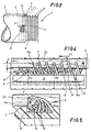
- figs 4 and 5 are respective details of fig 3, seen enlarged and partly in section, illustrating the step of securing two spiral wound elements to the blood vessel;
- fig 6 shows a further step in the procedure of inserting and implanting the prosthesis of fig 1, namely securing the prosthesis to the blood vessel, illustrated in perspective with certain parts omitted better to reveal others;
- figs 7, 7a and 8 show respective steps in an alternative method of inserting and implanting the prosthesis according to the invention, all of which illustrated in side elevation with certain parts omitted.
- Referring to the figures of the accompanying drawings, and in particular to fig 1, the present invention relates to a prosthesis (denoted 1 in its entirety) implantable in a section 4 of a
blood vessel 2 and comprising: a tubularcylindrical element 3, a pair of first spiral wound guide and locatingelements 6, also a pair of respective second spiralwound stitching elements 7. - The tubular
cylindrical element 3 is to all intents and purposes a flexible sleeve fashioned from a biocompatible material, for example Dacron™ (a proprietary polyester fibre made by Du Pont de Nemours, USA), such as can be implanted in a section 4 of ablood vessel 2 laid open as illustrated in fig 2 (the procedure to be described in due course). - The
sleeve 3 comprises a pair of firstrigid rings 5 located one at each end and embodied integrally with the tubular structure, such as can be offered in direct contact tocylindrical portions 2c of theblood vessel 2, and it is with these same firstrigid rings 5 that the aforementioned first spiral wound guide and locating elements 6 (likewise fashioned from a biocompatible material) are associated; more precisely, each firstspiral wound element 6 ensheaths and remains permanently associated with afiliform element 8 or second ring which in turn encircles an external portion of the relative firstrigid ring 5, occupying a circumferential channel denoted 9. Thefiliform element 8 can be anchored by oneend 8a, which is bent inwards and insertable thus into asocket 15 afforded by thefirst ring 5. - Similarly, in an alternative solution (see also figs 7 and 8), each first
spiral wound element 6 ensheaths and is permanently associated likewise with afiliform element 8 or second ring similar to that described previously, though in this instance extending circumferentially around an internal portion of the firstrigid ring 5, occupying an inward-facingcircumferential channel 10. - Each first
spiral wound element 6 is ensheathed in turn by the relative second or stitchingspiral wound element 7, which again will be fashioned in a biocompatible material; this samesecond element 7 is embodied with asharp point 7a and proportioned such that when rotated helically around the respective firstspiral wound element 6 and caused thus to advance along its own longitudinal axis X, the firstrigid ring 5 will be secured circumferentially and continuously to the relativecylindrical portion 2c of the blood vessel 2: as the point is rotated, in effect, a given thickness S of thecylindrical portion 2c will become interposed between the twospiral wound elements - In practice (see fig 4), the internal diameter Di of the second
spiral wound element 7 is greater than the external diameter De of the respective firstspiral wound element 6, and the secondspiral wound element 7 functions exactly in the manner of a worm or lead screw, winding around and at the same time advancing along the firstspiral wound element 6 in such a way as to pierce, or rather "stitch" the wall of thecylindrical portion 2c (see arrow F) to a given depth S, from either the inside or the outside. Accordingly, a portion of theblood vessel 2 remains pinned to this same depth S, which corresponds to the difference between the two aforementioned diameters Di and De, by a continuous succession of stitches of which the frequency or gauge is determined by the distance between successive single coils of the secondspiral wound element 7. The result is to establish a permanent association between the firstrigid ring 5 and thecylindrical portion 2c of theblood vessel 2. - A method by which the
prosthesis 1 of the present invention is inserted into ablood vessel 2 affected with a localized swelling R and the aforementioned permanent association duly obtained, comprises a succession of steps now to be described (see figs 2, 3 and 6). - In a first solution, which utilizes first
spiral wound elements 6 located externally of the firstrigid rings 5, the steps are those of: - -a) making incisions in the
blood vessel 2 at the site of the swelling R both longitudinally and around some two thirds of the circumference of the vessel at the respective areas ofcontact 11 between the swelling R and the healthy stretches on either side, in such a manner as to create anopening 12 in the wall of thevessel 2 and a pair of mutually opposedflaps - -b) inserting the
sleeve 3 into theopening 12 in such a way that the tworigid rings 5 are accommodated internally of the correspondingcylindrical portions 2c of theblood vessel 2 on either side of the opening (see fig 3); - -c) securing the two
cylindrical portions 2c of theblood vessel 2 to the respective firstrigid rings 5 by screwing each secondspiral wound element 7 around the corresponding firstspiral wound element 6 and along its own longitudinal axis X (see arrow F) through at least 360° about the axis of the tubularcylindrical element 3, in such a manner as to anchor a portion of thecylindrical portion 2c between the firstspiral wound element 6 and the secondspiral wound element 7, of which the thickness S (as already intimated) is equivalent at least to the difference between the internal diameter Di and the external diameter De respectively of the secondspiral wound element 7 and of the first spiral wound element 6 (see figs 4 and 6); in performing this particular step, the surgeon will take care to keep eachcylindrical portion 2c pressed steadily against the relative firstrigid ring 5 so as to ensure faultless contact during the stitching process; and, - -d) finally, flattening the two
flaps sleeve 3 and suturing the edges to encapsulate the prosthesis internally of the repair. -
- By contrast, in the event that the first
spiral wound elements 6 extend circumferentially aroundchannels 10 facing toward the inside of the sleeve, the procedure would comprise the steps of: - -a) excising at least the part of the
blood vessel 2 that exhibits the swelling R, in such a manner as to produce two distinct and mutually opposedopen ends 2c of the healthy vessel separated by a distance L less than the longitudinal dimension of the sleeve 3 (see fig 7a); - -b) interposing the
sleeve 3 between the twoopen ends 2c, in such a way that eachend 2c is inserted into a respective first rigid ring 5 (see fig 7); - -c) introducing an expandable element 20 (a conventional
balloon, for example, as illustrated in fig 8) into the
blood vessel 2 at a point remote from the site of the implant, utilizing aconventional catheter 21 by means of which theelement 20 can be positioned to coincide with the twoopen ends 2c; thereafter, inflating theelement 20 first at one end and then at the other, in such a way as to establish a firm core around which the cylindrical configuration of theopen ends 2c can be maintained during the subsequent step; - -d) securing the two cylindrical
open ends 2c of theblood vessel 2 to the respective firstrigid rings 5 by screwing each secondspiral wound element 7 around the corresponding first spiral wound element 6 (and along its own longitudinal axis X) through at least 360° about the axis of the tubularcylindrical element 3, in such a way that a given thickness S of theopen end 2c remains anchored permanently between the firstspiral wound element 6 and the second spiral wound element 7 (see fig 8) . In both of the procedures described above, the step of securing the ends is followed by the further step of: - -e) trimming off the excess length of each second
spiral wound element 7 that remains outside the dimensional compass of thesleeve 3, i.e. the part not utilized in effecting the stitching operation (see fig 6). -
- More exactly, before the
sleeve 3 is offered to thecylindrical portions 2c (in the first solution illustrated) or the cylindricalopen ends 2c (in the latter instance), the secondspiral wound elements 7 are anchored by theirsharp points 7a to the respective firstspiral wound elements 6, each with the remaining length trailing loose externally of thesleeve 3. - This initial arrangement notably facilitates the task of the surgeon, who has no need to verify whether or not the second
spiral wound element 7 is correctly coupled with the firstspiral wound element 6 when embarking on the step of screwing the one around and along the other. - The step of screwing the second
spiral wound element 7 into place is accomplished preferably by coupling theend 7b remote from thesharp point 7a with aspindle 70 connected rotatably to apower driver 71, so that the time taken to effect the stitching operation proper will be significantly minimized. - As discernible from the foregoing specification, the object stated at the outset is realized by the prosthesis disclosed with notable advantages: adopting the structural arrangement of a sleeve and two spiral wound elements, the time taken to stitch the sleeve in place is reduced markedly in comparison to earlier conventional methods, thus making a positive impact on the surgical operation as a whole; with the two spiral wound elements, moreover, the blood vessel is anchored by a succession of closely spaced stitches certain to provide a sound mechanical bond and efficiently contain the flow of blood through the vessel.
Claims (6)
- A prosthesis (1) for a blood vessel (2), comprising a tubular cylindrical element (3) of biocompatible material implantable in a section (4) of the opened blood vessel (2) and affording a pair of first rigidly embodied rings (5) positioned one at either end, such as can be disposed in direct contact with corresponding cylindrical portions (2c) of the blood vessel (2), also a pair of first spiral wound guide and locating elements (6) fashioned likewise in a biocompatible material, respectively associated with and extending circumferentially around the first rigid rings (5) through an angular distance not less than 360°, each freely and slidably ensheathed by a respective second spiral wound stitching element (7) of biocompatible material furnished with a sharp point (7a) in which sliding movement is induced by rotation about its own longitudinal axis (X), such that when each of the second spiral wound elements (7) is rotated helically about the respective first spiral wound element (6) and caused thus to advance along its own axis (X), the first rigid rings (5) are anchored stably and continuously to the relative cylindrical portions (2c) as a given thickness (S) of each cylindrical portion (2c) becomes interposed between the two spiral wound elements (6, 7).
- A prosthesis as in claim 1, wherein the second spiral wound element (7) exhibits an internal diameter (Di) greater than the external diameter (De) of the respective first spiral wound element (6), such that a given thickness (S) of the corresponding cylindrical portion (2c) can be interposed within the space afforded by the difference between the two diameters (Di, De).
- A prosthesis as in claim 1, wherein the first spiral wound element (6) ensheaths and is permanently associated with a filiform element (8) performing the function of a second ring extending circumferentially and externally around each of the first rigid rings (5) and stably associated therewith through a distance not less than 360°.
- A prosthesis as in claim 1, wherein the first spiral wound element (6) ensheaths and is permanently associated with a filiform element (8) performing the function of a second ring extending circumferentially and internally around each of the first rigid rings (5) and stably associated therewith through a distance not less than 360°.
- A prosthesis as in claim 3 or 4, wherein the filiform element (8) is seated in a circumferential channel (9, 10) afforded by the first rigid ring (5).
- A prosthesis as in claim 1 wherein the tubular cylindrical element (3) consists in a flexible sleeve with the pair of rigid rings (5) embodied integrally one at either end.
Applications Claiming Priority (3)
| Application Number | Priority Date | Filing Date | Title |
|---|---|---|---|
| ITBO940552A IT1273855B (en) | 1994-12-16 | 1994-12-16 | PROSTHESIS FOR VENOUS CAVITY |
| ITBO940552 | 1994-12-16 | ||
| PCT/IT1995/000218 WO1996018360A1 (en) | 1994-12-16 | 1995-12-13 | A prosthesis for a blood vessel |
Publications (2)
| Publication Number | Publication Date |
|---|---|
| EP0797414A1 EP0797414A1 (en) | 1997-10-01 |
| EP0797414B1 true EP0797414B1 (en) | 2001-08-29 |
Family
ID=11340155
Family Applications (1)
| Application Number | Title | Priority Date | Filing Date |
|---|---|---|---|
| EP95940411A Expired - Lifetime EP0797414B1 (en) | 1994-12-16 | 1995-12-13 | A prosthesis for a blood vessel |
Country Status (9)
| Country | Link |
|---|---|
| US (1) | US5800524A (en) |
| EP (1) | EP0797414B1 (en) |
| JP (1) | JPH10511865A (en) |
| BR (1) | BR9510020A (en) |
| CA (1) | CA2206341C (en) |
| DE (1) | DE69522470T2 (en) |
| ES (1) | ES2163532T3 (en) |
| IT (1) | IT1273855B (en) |
| WO (1) | WO1996018360A1 (en) |
Families Citing this family (31)
| Publication number | Priority date | Publication date | Assignee | Title |
|---|---|---|---|---|
| US6331188B1 (en) | 1994-08-31 | 2001-12-18 | Gore Enterprise Holdings, Inc. | Exterior supported self-expanding stent-graft |
| US6015429A (en) | 1994-09-08 | 2000-01-18 | Gore Enterprise Holdings, Inc. | Procedures for introducing stents and stent-grafts |
| US7204848B1 (en) | 1995-03-01 | 2007-04-17 | Boston Scientific Scimed, Inc. | Longitudinally flexible expandable stent |
| US6042605A (en) | 1995-12-14 | 2000-03-28 | Gore Enterprose Holdings, Inc. | Kink resistant stent-graft |
| JP2000503559A (en) | 1995-12-14 | 2000-03-28 | ゴア エンタープライズ ホールディングス,インコーポレイティド | Apparatus and method for deploying a stent-graft |
| US5871537A (en) * | 1996-02-13 | 1999-02-16 | Scimed Life Systems, Inc. | Endovascular apparatus |
| US6551350B1 (en) * | 1996-12-23 | 2003-04-22 | Gore Enterprise Holdings, Inc. | Kink resistant bifurcated prosthesis |
| US6352561B1 (en) | 1996-12-23 | 2002-03-05 | W. L. Gore & Associates | Implant deployment apparatus |
| US6494904B1 (en) * | 1996-12-27 | 2002-12-17 | Ramus Medical Technologies | Method and apparatus for forming vascular prostheses |
| US5944750A (en) * | 1997-06-30 | 1999-08-31 | Eva Corporation | Method and apparatus for the surgical repair of aneurysms |
| US6395019B2 (en) | 1998-02-09 | 2002-05-28 | Trivascular, Inc. | Endovascular graft |
| US5989287A (en) * | 1998-05-06 | 1999-11-23 | Av Healing Llc | Vascular graft assemblies and methods for implanting same |
| US6926724B1 (en) * | 1999-05-04 | 2005-08-09 | City Of Hope | Visceral anastomotic device and method of using same |
| IT1307268B1 (en) | 1999-09-30 | 2001-10-30 | Sorin Biomedica Cardio Spa | DEVICE FOR HEART VALVE REPAIR OR REPLACEMENT. |
| DE10147632B4 (en) * | 2001-06-08 | 2005-10-20 | Fraunhofer Ges Forschung | Device for connecting hollow organs and / or closing wall defects of hollow organs |
| US6902570B2 (en) | 2001-06-08 | 2005-06-07 | Rolf Dieter Schraft | Device and method for connecting hollow organs and/or sealing wall defects in hollow organs |
| US7104949B2 (en) * | 2001-08-31 | 2006-09-12 | Ams Research Corporation | Surgical articles for placing an implant about a tubular tissue structure and methods |
| US20060004393A1 (en) * | 2004-05-13 | 2006-01-05 | Amarant Paul D | Percutaneous anastomosis connection system |
| US7988720B2 (en) | 2006-09-12 | 2011-08-02 | Boston Scientific Scimed, Inc. | Longitudinally flexible expandable stent |
| EP1982658A1 (en) * | 2007-04-16 | 2008-10-22 | Corlife GbR | Vessel connector and kit with applicator for surgery |
| US8226701B2 (en) | 2007-09-26 | 2012-07-24 | Trivascular, Inc. | Stent and delivery system for deployment thereof |
| US8663309B2 (en) | 2007-09-26 | 2014-03-04 | Trivascular, Inc. | Asymmetric stent apparatus and method |
| US8066755B2 (en) | 2007-09-26 | 2011-11-29 | Trivascular, Inc. | System and method of pivoted stent deployment |
| CN101917929A (en) | 2007-10-04 | 2010-12-15 | 特里瓦斯库拉尔公司 | Modular vascular graft for low profile percutaneous delivery |
| US8083789B2 (en) | 2007-11-16 | 2011-12-27 | Trivascular, Inc. | Securement assembly and method for expandable endovascular device |
| US8328861B2 (en) | 2007-11-16 | 2012-12-11 | Trivascular, Inc. | Delivery system and method for bifurcated graft |
| CN102141059B (en) * | 2011-03-29 | 2013-07-24 | 江苏武进液压启闭机有限公司 | Method for detecting absolute displacement of ceramic piston rod |
| CN102141060B (en) * | 2011-03-29 | 2013-07-24 | 江苏武进液压启闭机有限公司 | Device for detecting absolute displacement of ceramic piston rod |
| US8992595B2 (en) | 2012-04-04 | 2015-03-31 | Trivascular, Inc. | Durable stent graft with tapered struts and stable delivery methods and devices |
| US9498363B2 (en) | 2012-04-06 | 2016-11-22 | Trivascular, Inc. | Delivery catheter for endovascular device |
| US20170042551A1 (en) * | 2015-08-13 | 2017-02-16 | The Brain Protection Company PTY LTD | Implantable damping devices for treating dementia and associated systems and methods of use |
Family Cites Families (11)
| Publication number | Priority date | Publication date | Assignee | Title |
|---|---|---|---|---|
| US3774615A (en) * | 1971-02-08 | 1973-11-27 | Ceskoslovenska Akademie Ved | Device for connecting or joining the ends of interrupted tubular organs in surgical operations without stitching |
| US4190909A (en) * | 1978-03-31 | 1980-03-04 | Ablaza Sariel G G | Apparatus and method for surgical repair of dissecting thoracic aneurysms and the like |
| US4368736A (en) * | 1980-11-17 | 1983-01-18 | Kaster Robert L | Anastomotic fitting |
| US4769029A (en) * | 1987-06-19 | 1988-09-06 | Patel Jayendrakumar I | Prosthetic graft for arterial system repair |
| JP2561853B2 (en) * | 1988-01-28 | 1996-12-11 | 株式会社ジェイ・エム・エス | Shaped memory molded article and method of using the same |
| SU1754094A1 (en) * | 1990-03-11 | 1992-08-15 | В.В.Емель нов.; ;. -.- | Intravascular framework |
| US5127413A (en) * | 1990-08-09 | 1992-07-07 | Ebert Edward A | Sinous suture |
| GB2269104A (en) * | 1992-04-09 | 1994-02-02 | Taha Roudan Lazim | Vascular graft apparatus |
| US5330490A (en) * | 1992-04-10 | 1994-07-19 | Wilk Peter J | Endoscopic device, prosthesis and method for use in endovascular repair |
| DE4304353A1 (en) * | 1992-10-24 | 1994-04-28 | Helmut Dipl Ing Wurster | Suturing device used in endoscopic surgical operations - has helical needle with fixed non-traumatic thread held and rotated by rollers attached to instrument head extended into patients body. |
| IT1269443B (en) * | 1994-01-19 | 1997-04-01 | Stefano Nazari | VASCULAR PROSTHESIS FOR THE REPLACEMENT OR INTERNAL COATING OF MEDIUM AND LARGE DIAMETER BLOOD VESSELS AND DEVICE FOR ITS APPLICATION WITHOUT INTERRUPTION OF BLOOD FLOW |
-
1994
- 1994-12-16 IT ITBO940552A patent/IT1273855B/en active IP Right Grant
-
1995
- 1995-12-13 BR BR9510020A patent/BR9510020A/en not_active Application Discontinuation
- 1995-12-13 ES ES95940411T patent/ES2163532T3/en not_active Expired - Lifetime
- 1995-12-13 EP EP95940411A patent/EP0797414B1/en not_active Expired - Lifetime
- 1995-12-13 DE DE69522470T patent/DE69522470T2/en not_active Expired - Fee Related
- 1995-12-13 JP JP8518563A patent/JPH10511865A/en not_active Ceased
- 1995-12-13 WO PCT/IT1995/000218 patent/WO1996018360A1/en active IP Right Grant
- 1995-12-13 CA CA002206341A patent/CA2206341C/en not_active Expired - Fee Related
- 1995-12-13 US US08/849,681 patent/US5800524A/en not_active Expired - Lifetime
Also Published As
| Publication number | Publication date |
|---|---|
| DE69522470T2 (en) | 2002-05-08 |
| WO1996018360A1 (en) | 1996-06-20 |
| ITBO940552A1 (en) | 1996-06-16 |
| ES2163532T3 (en) | 2002-02-01 |
| BR9510020A (en) | 1998-06-02 |
| AU4187396A (en) | 1996-07-03 |
| AU694826B2 (en) | 1998-07-30 |
| EP0797414A1 (en) | 1997-10-01 |
| DE69522470D1 (en) | 2001-10-04 |
| IT1273855B (en) | 1997-07-11 |
| CA2206341C (en) | 2006-07-04 |
| ITBO940552A0 (en) | 1994-12-16 |
| CA2206341A1 (en) | 1996-06-20 |
| US5800524A (en) | 1998-09-01 |
| JPH10511865A (en) | 1998-11-17 |
Similar Documents
| Publication | Publication Date | Title |
|---|---|---|
| EP0797414B1 (en) | A prosthesis for a blood vessel | |
| US5713917A (en) | Apparatus and method for engrafting a blood vessel | |
| US6852116B2 (en) | Method for engrafting a blood vessel | |
| US8696689B2 (en) | Medical suturing device and method for use thereof | |
| US5895404A (en) | Apparatus and methods for percutaneously forming a passageway between adjacent vessels or portions of a vessel | |
| US5820631A (en) | Device and method for suturing tissue adjacent to a blood vessel | |
| US4327709A (en) | Apparatus and method for the percutaneous introduction of intra-aortic balloons into the human body | |
| US6926723B1 (en) | Implantable prosthesis and method and apparatus for loading and delivering an implantable prosthesis | |
| US20100106171A1 (en) | Transcaval mesenteric venous anastomosis and access system | |
| EP1917913A2 (en) | Placement system for an implant | |
| JPH0838486A (en) | System and method for forked form multicapsule pipe intracavitary transplant | |
| JP5329594B2 (en) | Device for joining vessels | |
| EP1126795A2 (en) | Medical graft connector component and methods of making and installing same | |
| US11413043B2 (en) | Anchor device for vascular anastomosis | |
| WO2011067756A1 (en) | Device system and method for tissue access site closure | |
| US6059821A (en) | Method for controlling circulation of blood in a body | |
| CN109833112B (en) | Intraoperative stent and application method thereof | |
| CN107072649A (en) | Biological absorbable wound closure device and method | |
| CN113747861A (en) | Systems, devices, and methods for remodeling a valve annulus | |
| AU694826C (en) | A prosthesis for a blood vessel | |
| JP5306212B2 (en) | Artificial blood vessel |
Legal Events
| Date | Code | Title | Description |
|---|---|---|---|
| PUAI | Public reference made under article 153(3) epc to a published international application that has entered the european phase |
Free format text: ORIGINAL CODE: 0009012 |
|
| 17P | Request for examination filed |
Effective date: 19970614 |
|
| AK | Designated contracting states |
Kind code of ref document: A1 Designated state(s): BE CH DE DK ES FR GB IE IT LI NL PT SE |
|
| RAP1 | Party data changed (applicant data changed or rights of an application transferred) |
Owner name: BARD GALWAY LIMITED |
|
| RAP1 | Party data changed (applicant data changed or rights of an application transferred) |
Owner name: C.R. BARD, INC. |
|
| GRAG | Despatch of communication of intention to grant |
Free format text: ORIGINAL CODE: EPIDOS AGRA |
|
| 17Q | First examination report despatched |
Effective date: 20001110 |
|
| GRAG | Despatch of communication of intention to grant |
Free format text: ORIGINAL CODE: EPIDOS AGRA |
|
| GRAH | Despatch of communication of intention to grant a patent |
Free format text: ORIGINAL CODE: EPIDOS IGRA |
|
| GRAH | Despatch of communication of intention to grant a patent |
Free format text: ORIGINAL CODE: EPIDOS IGRA |
|
| GRAA | (expected) grant |
Free format text: ORIGINAL CODE: 0009210 |
|
| AK | Designated contracting states |
Kind code of ref document: B1 Designated state(s): BE CH DE DK ES FR GB IE IT LI NL PT SE |
|
| PG25 | Lapsed in a contracting state [announced via postgrant information from national office to epo] |
Ref country code: NL Free format text: LAPSE BECAUSE OF FAILURE TO SUBMIT A TRANSLATION OF THE DESCRIPTION OR TO PAY THE FEE WITHIN THE PRESCRIBED TIME-LIMIT Effective date: 20010829 Ref country code: LI Free format text: LAPSE BECAUSE OF FAILURE TO SUBMIT A TRANSLATION OF THE DESCRIPTION OR TO PAY THE FEE WITHIN THE PRESCRIBED TIME-LIMIT Effective date: 20010829 Ref country code: CH Free format text: LAPSE BECAUSE OF FAILURE TO SUBMIT A TRANSLATION OF THE DESCRIPTION OR TO PAY THE FEE WITHIN THE PRESCRIBED TIME-LIMIT Effective date: 20010829 Ref country code: BE Free format text: LAPSE BECAUSE OF FAILURE TO SUBMIT A TRANSLATION OF THE DESCRIPTION OR TO PAY THE FEE WITHIN THE PRESCRIBED TIME-LIMIT Effective date: 20010829 |
|
| REG | Reference to a national code |
Ref country code: CH Ref legal event code: EP |
|
| REG | Reference to a national code |
Ref country code: IE Ref legal event code: FG4D |
|
| REF | Corresponds to: |
Ref document number: 69522470 Country of ref document: DE Date of ref document: 20011004 |
|
| PG25 | Lapsed in a contracting state [announced via postgrant information from national office to epo] |
Ref country code: SE Free format text: LAPSE BECAUSE OF FAILURE TO SUBMIT A TRANSLATION OF THE DESCRIPTION OR TO PAY THE FEE WITHIN THE PRESCRIBED TIME-LIMIT Effective date: 20011129 Ref country code: PT Free format text: LAPSE BECAUSE OF FAILURE TO SUBMIT A TRANSLATION OF THE DESCRIPTION OR TO PAY THE FEE WITHIN THE PRESCRIBED TIME-LIMIT Effective date: 20011129 Ref country code: DK Free format text: LAPSE BECAUSE OF FAILURE TO SUBMIT A TRANSLATION OF THE DESCRIPTION OR TO PAY THE FEE WITHIN THE PRESCRIBED TIME-LIMIT Effective date: 20011129 |
|
| PG25 | Lapsed in a contracting state [announced via postgrant information from national office to epo] |
Ref country code: IE Free format text: LAPSE BECAUSE OF FAILURE TO SUBMIT A TRANSLATION OF THE DESCRIPTION OR TO PAY THE FEE WITHIN THE PRESCRIBED TIME-LIMIT Effective date: 20011213 |
|
| REG | Reference to a national code |
Ref country code: GB Ref legal event code: IF02 |
|
| EN | Fr: translation not filed | ||
| NLV1 | Nl: lapsed or annulled due to failure to fulfill the requirements of art. 29p and 29m of the patents act | ||
| REG | Reference to a national code |
Ref country code: ES Ref legal event code: FG2A Ref document number: 2163532 Country of ref document: ES Kind code of ref document: T3 |
|
| REG | Reference to a national code |
Ref country code: CH Ref legal event code: PL |
|
| PLBE | No opposition filed within time limit |
Free format text: ORIGINAL CODE: 0009261 |
|
| STAA | Information on the status of an ep patent application or granted ep patent |
Free format text: STATUS: NO OPPOSITION FILED WITHIN TIME LIMIT |
|
| 26N | No opposition filed | ||
| REG | Reference to a national code |
Ref country code: IE Ref legal event code: MM4A |
|
| ET | Fr: translation filed | ||
| REG | Reference to a national code |
Ref country code: FR Ref legal event code: ERR Free format text: BOPI DE PUBLICATION N: 02/04 PAGES: 243 PARTIE DU BULLETIN CONCERNEE: BREVETS EUROPEENS DONT LA TRADUCTION N'A PAS ETE REMISE A I'INPI IL Y A LIEU DE SUPPRIMER: LA MENTION DE LA NON REMISE. LA REMISE DE LA TRADUCTION EST PUBLIEE DANS LE PRESENT BOPI. |
|
| PGFP | Annual fee paid to national office [announced via postgrant information from national office to epo] |
Ref country code: ES Payment date: 20080118 Year of fee payment: 13 |
|
| PGFP | Annual fee paid to national office [announced via postgrant information from national office to epo] |
Ref country code: IT Payment date: 20071228 Year of fee payment: 13 Ref country code: DE Payment date: 20071206 Year of fee payment: 13 |
|
| PG25 | Lapsed in a contracting state [announced via postgrant information from national office to epo] |
Ref country code: DE Free format text: LAPSE BECAUSE OF NON-PAYMENT OF DUE FEES Effective date: 20090701 |
|
| REG | Reference to a national code |
Ref country code: ES Ref legal event code: FD2A Effective date: 20081215 |
|
| PG25 | Lapsed in a contracting state [announced via postgrant information from national office to epo] |
Ref country code: ES Free format text: LAPSE BECAUSE OF NON-PAYMENT OF DUE FEES Effective date: 20081215 |
|
| PGFP | Annual fee paid to national office [announced via postgrant information from national office to epo] |
Ref country code: FR Payment date: 20101224 Year of fee payment: 16 |
|
| PGFP | Annual fee paid to national office [announced via postgrant information from national office to epo] |
Ref country code: GB Payment date: 20101208 Year of fee payment: 16 |
|
| GBPC | Gb: european patent ceased through non-payment of renewal fee |
Effective date: 20111213 |
|
| REG | Reference to a national code |
Ref country code: FR Ref legal event code: ST Effective date: 20120831 |
|
| PG25 | Lapsed in a contracting state [announced via postgrant information from national office to epo] |
Ref country code: GB Free format text: LAPSE BECAUSE OF NON-PAYMENT OF DUE FEES Effective date: 20111213 |
|
| PG25 | Lapsed in a contracting state [announced via postgrant information from national office to epo] |
Ref country code: FR Free format text: LAPSE BECAUSE OF NON-PAYMENT OF DUE FEES Effective date: 20120102 |
|
| PG25 | Lapsed in a contracting state [announced via postgrant information from national office to epo] |
Ref country code: IT Free format text: LAPSE BECAUSE OF NON-PAYMENT OF DUE FEES Effective date: 20081213 |