EP0800103A2 - Fiber optic switching device and method using free space scanning - Google Patents
Fiber optic switching device and method using free space scanning Download PDFInfo
- Publication number
- EP0800103A2 EP0800103A2 EP97302012A EP97302012A EP0800103A2 EP 0800103 A2 EP0800103 A2 EP 0800103A2 EP 97302012 A EP97302012 A EP 97302012A EP 97302012 A EP97302012 A EP 97302012A EP 0800103 A2 EP0800103 A2 EP 0800103A2
- Authority
- EP
- European Patent Office
- Prior art keywords
- fiber
- light
- fibers
- fiber bundle
- collimator
- Prior art date
- Legal status (The legal status is an assumption and is not a legal conclusion. Google has not performed a legal analysis and makes no representation as to the accuracy of the status listed.)
- Withdrawn
Links
Images

Classifications
-
- G—PHYSICS
- G02—OPTICS
- G02B—OPTICAL ELEMENTS, SYSTEMS OR APPARATUS
- G02B6/00—Light guides; Structural details of arrangements comprising light guides and other optical elements, e.g. couplings
- G02B6/24—Coupling light guides
- G02B6/26—Optical coupling means
- G02B6/35—Optical coupling means having switching means
- G02B6/3586—Control or adjustment details, e.g. calibrating
- G02B6/359—Control or adjustment details, e.g. calibrating of the position of the moving element itself during switching, i.e. without monitoring the switched beams
-
- G—PHYSICS
- G02—OPTICS
- G02B—OPTICAL ELEMENTS, SYSTEMS OR APPARATUS
- G02B6/00—Light guides; Structural details of arrangements comprising light guides and other optical elements, e.g. couplings
- G02B6/24—Coupling light guides
- G02B6/26—Optical coupling means
- G02B6/35—Optical coupling means having switching means
- G02B6/351—Optical coupling means having switching means involving stationary waveguides with moving interposed optical elements
- G02B6/3512—Optical coupling means having switching means involving stationary waveguides with moving interposed optical elements the optical element being reflective, e.g. mirror
-
- G—PHYSICS
- G02—OPTICS
- G02B—OPTICAL ELEMENTS, SYSTEMS OR APPARATUS
- G02B6/00—Light guides; Structural details of arrangements comprising light guides and other optical elements, e.g. couplings
- G02B6/24—Coupling light guides
- G02B6/26—Optical coupling means
- G02B6/35—Optical coupling means having switching means
- G02B6/351—Optical coupling means having switching means involving stationary waveguides with moving interposed optical elements
- G02B6/3524—Optical coupling means having switching means involving stationary waveguides with moving interposed optical elements the optical element being refractive
- G02B6/3528—Optical coupling means having switching means involving stationary waveguides with moving interposed optical elements the optical element being refractive the optical element being a prism
-
- G—PHYSICS
- G02—OPTICS
- G02B—OPTICAL ELEMENTS, SYSTEMS OR APPARATUS
- G02B6/00—Light guides; Structural details of arrangements comprising light guides and other optical elements, e.g. couplings
- G02B6/24—Coupling light guides
- G02B6/26—Optical coupling means
- G02B6/35—Optical coupling means having switching means
- G02B6/354—Switching arrangements, i.e. number of input/output ports and interconnection types
- G02B6/3554—3D constellations, i.e. with switching elements and switched beams located in a volume
- G02B6/3556—NxM switch, i.e. regular arrays of switches elements of matrix type constellation
-
- G—PHYSICS
- G02—OPTICS
- G02B—OPTICAL ELEMENTS, SYSTEMS OR APPARATUS
- G02B6/00—Light guides; Structural details of arrangements comprising light guides and other optical elements, e.g. couplings
- G02B6/24—Coupling light guides
- G02B6/26—Optical coupling means
- G02B6/35—Optical coupling means having switching means
- G02B6/3564—Mechanical details of the actuation mechanism associated with the moving element or mounting mechanism details
- G02B6/3568—Mechanical details of the actuation mechanism associated with the moving element or mounting mechanism details characterised by the actuating force
Definitions
- the present invention relates to fiber optic switches used for optically connecting at least one optical fiber to at least one other optical fiber.
- OTDR optical time domain reflectometry
- the light source of a testing apparatus is selectively coupled to the fibers in a network, thereby providing a means for testing each of the fibers within the network.
- the output of the testing light source must be switched to each of the fibers in the network during the testing period.
- a single OTDR testing apparatus is typically shared by a large number (N) of fibers in a network using a 1 X N switching arrangement.
- N large number
- Arbitrarily large switches have been constructed from smaller banks of optomechanical switches.
- the cost of the switching configuration grows proportionately.
- a simple way to provide optical fiber switching has been to perform the switching manually, via manually operated switchboard panels.
- Such switchboard panels use mechanically manipulated connectors.
- the use of mechanically operated switchboard panels is limited to applications where the number of fibers to be switched is relatively small and a slow switching time is acceptable.
- optomechanical switches have a switching response of the order 10 ms - 50 ms, which is far more rapid than is possible for a manually operated switchboard panel. Furthermore, optomechanical switches have good crosstalk, back reflection, insertion loss characteristics and are relatively inexpensive compared to faster integrated optics switches.
- a lensed input fiber is mechanically moved across a bank of lensed output fibers. As the lensed input fiber passes each lensed output fiber, the optical signal from the lensed input fiber is optically transferred to the lensed output fiber.
- optomechanical switches require that a lensed input fiber be mechanically moved across a bank of lensed output fibers, optomechanical switches are well adapted for applications where output fibers in a bank are sequentially coupled to a source fiber, such as in the previously described OTDR testing procedure.
- microlenses For conventional optomechanical switches, microlenses must be aligned to each fiber being tested. In other conventional switching arrangements, such as those that use electro-optic waveguides, alignment procedures to align the switching device to each fiber being tested must also be employed. In applications requiring larger switches, the cost of fiber alignment is the dominant cost, wherein the cost of aligning the switching device is more expensive than the switching device itself. As a result, the overall cost of using a switching assembly has been directly proportional to the number of fibers to be switched.
- an optical switch employs a free space optical arrangement, wherein a signal from a source fiber is reflected through an optical system and redirected to other fibers.
- This switch uses of a quarter period graded-refractive-index rod lens, wherein the input and the output fibers are arranged in a circular configuration. An input fiber is placed at the center of the graded-refractive-index rod lens.
- the signal from the input fiber passes through the center of the lens, reflects off a rotating mirror and is directed to one of the output fibers that are positioned along a circular path around the center input fiber.
- This switch configuration is also limited in its application because the spot positioning accuracy is insufficient for single mode fibers.
- the present invention is an optical switching device and method for selectively optically connecting at least one input fiber in a fiber bundle to at least one output fiber in a fiber bundle.
- a light directing mechanism is provided proximate a face of a fiber bundle that contains the input fiber.
- the light from the input fiber is directed toward the output fibers by varying the orientation of the light directing mechanism relative the face of the fiber bundle.
- the light directing mechanism thereby enables the light from the input fiber to be selectively directed to each of the output fibers.
- the orientation of the light directing mechanism By selectively controlling the orientation of the light directing mechanism, the light from the input fiber can be scanned to any number of output fibers, thereby producing a 1 X N optical switch.
- the present invention switching system and method can be used in a number of different applications where it is desired to selectively optically connect at least one input fiber in a fiber bundle to a least one output fiber in the same or different fiber bundle.
- the present invention switching system and method are particularly useful in the optical time domain reflectometry (OTDR) testing of fibers in a network. Accordingly, the present invention system and method will be described with regard to an exemplary OTDR testing application.
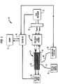
- the present invention switching system 10 is shown in conjunction with a fiber bundle 12.
- the size and configuration of the fiber bundle 12 is not critical to practicing the present invention.
- the fiber bundle 12 can be an organized array of individual optical fibers or can be any collection of fibers or groups of fibers in a configuration that is not organized.
- the fiber bundle 12 can contain any number of individual fibers.
- a fiber contained within the fiber bundle 12 is selected as the input fiber 14 and is coupled to an optical signal source 16. It is possible for the input fiber 14 to terminate at any location on a face 13 of the fiber bundle 12. As such, the input fiber 14 need not be in the center of the fiber bundle 12.
- a fiber 18 contained within the fiber bundle 12 can be selected as the calibration fiber and can be coupled to a calibration detector 20. The selected calibration fiber 18 can also terminate at a location on the fiber bundle face 13 which does not correspond to the bundle's center. The remainder of the fibers extending from the fiber bundle 12 opposite the fiber bundle face 13 are considered output fibers 22 and it is these output fibers 22 that can be selectively optically connected to the input fiber 14.
- a collimator lens assembly 24 is positioned in front of the face 13 of the fiber bundle 12.
- the collimator lens assembly 24 contains at least one lens that collimates the light emitted from the input fiber 14 at the face 13 of the fiber bundle 12.
- the collimator lens assembly 24 should be proportionately sized with respect to the fiber bundle 12 so that the light emitted by the input fiber 14 will be collimated by the collimator lens assembly 24 substantially independent of the location of the input fiber 14 within the fiber bundle 12.
- a reflector such as a mirror 30 is positioned at a location so as to receive the collimated light passing through the collimator lens assembly 24. As light impinges upon the mirror 30, the light is reflected back through the collimator lens assembly 24, wherein the reflected light becomes uncollimated and is focused at a particular location on the face 13 of the fiber bundle 12.
- the mirror 30 is coupled to a scan mechanism 32 that enables the orientation of the mirror 30 to be varied relative the path of the collimated light that impinges upon the mirror 30.
- the scan mechanism 32 can be an electromechanical mechanism coupled to the mirror 30 that can selectively change the orientation of the mirror 30 along a first and second axis. Alternatively, the scan mechanism can be an non mechanical device such as a liquid crystal or electro-optical deflector.
- the scan mechanism 32 enables the mirror 30 to selectively reflect light back against the face 13 of the fiber bundle 12 at any location on the fiber bundle face 13, substantially independent of the position of the input fiber 14 within the fiber bundle 12.
- the mirror 30 and the scan mechanism 32 act in unison to produce a light directing mechanism that is capable of selectively directing the collimated light passing through the collimator lens assembly 24 back through the collimator lens assembly 24 and to any location on the fiber bundle face 13.
- the present invention switching system 10 does not require the alignment of the individual fibers contained within the fiber bundle 12. As a result, when a fiber bundle 12 is first positioned in line with the collimator lens assembly 24, the position of the various output fibers 22 may be initially unknown. This requires the present invention switching system 10 to be calibrated prior to its use.
- an optical detector 36 such as an optical power meter, is placed in the optical path of the output fibers 22 within the fiber bundle 12. A strong light signal is then emitted through the input fiber 14, wherein the light is passed through the collimator lens assembly 24, reflected off the mirror 30, redirected through the collimator lens assembly 24 and focused at the fiber bundle face 13.
- the orientation of the mirror 30 is changed by the scan mechanism 32, thereby causing the reflected input fiber light to scan across the face 13 of the fiber bundle 12.
- each of the output fibers 22 in the fiber bundle 12 receives the reflected light for a corresponding time interval.
- the light scans across the core of an output fiber 22, the light is propagated along the core and is detected by the optical detector 36.
- the optical detector 36 measures an increased light intensity for a particular output fiber 22, it is known that the reflected light scanning over the fiber bundle face 13 was received by a core of that output fiber.
- a controller 40 is provided that is coupled to both the scan mechanism 32 and the optical detector 36. Each time the optical detector 36 detects increased light intensity from an output fiber 22, the controller 40 reads the positional address of the scan mechanism 32. That positional address is saved in a memory 41, wherein the memory 41 stores the positional address as corresponding to an output fiber 22. By scanning the face 13 of the fiber bundle 12, a scan mechanism positional address is obtained for each of the output fibers 22. The controller 40 therefore can determine the positional address of all the output fibers 22 in the fiber bundle 12. However, the identity of each output fiber at each positional address is not known. To determine the identity of each of the output fibers 22, each output fiber 22 in turn is connected individually to the optical detector 36. The light from the input fiber 12 is then directed to N known addresses on the fiber bundle face 13 so that the controller 40 can identify the specific positional address of each output fiber 22 on the face 13 of the fiber bundle 12.
- the optical detector 36 and the controller 40 need not be the same sophisticated devices used during calibration. Rather, the optical detector 36 can be any circuit capable of detecting the light from the input fiber 14 and the controller 40 can be a simple circuit with an EPROM memory.
- the calibration detector 20 is provided to compensate for any subtle changes in the position of the output fibers 22.
- the light from the input fiber 14 is intermittently scanned across the calibration fiber 18 on the face 13 of the fiber bundle 12. As the light strikes the calibration fiber 18, the intensity of the light is detected by the calibration detector 20. If the intensity of light detected by the calibration detector 20 changes, it is assumed that there has been a positional shift in the fiber bundle 12.
- the controller 40 coupled to the calibration detector 20, compensates the scan pattern until the calibration detector 20 again properly receives light from the input fiber 14. By correcting the scan pattern for the calibration detector 20, the scan pattern is corrected for all the other output fibers 22 in the fiber bundle 12.
- the shown embodiment uses only one calibration fiber 18 within the fiber bundle 12, it should be understood that a plurality of fibers in the fiber bundle 12 can be designated as calibration fibers and can be coupled to the calibration detector 20. By using a plurality of calibration fibers at different points within the fiber bundle 12, more accurate corrections can be made by the controller 40 should the initial position of the output fibers 22 in the fiber bundle 12 be slightly altered.
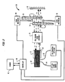
- FIG. 2 An alternate embodiment 50 of a switching system in accordance with the invention and having substantially increased light directing resolution is shown in FIG. 2.
- the fiber bundle 12, containing an input fiber 14, output fibers 22 and at least one calibration fiber 18 are substantially identical to those components depicted in FIG. 1 and are identified by like reference numbers for clarity.
- the collimator lens assembly 24 for collimating the light of the input fiber 14 is also substantially the same as the previous embodiment.
- a fixed mirror 52 is provided, wherein the plane of the fixed mirror 52 is perpendicular to the path of the collimated light passing through the collimator lens assembly 24.
- a light directing mechanism Disposed between the collimator lens assembly 24 and the fixed mirror 52 is a light directing mechanism that includes two prisms 54, 56 coupled to a rotating scan mechanism 58, 59 that enables each prism 54, 56 to be rotated.
- the rotating scan mechanisms 58, 59 can include most any rotating control but preferably include galvo scanners.
- the two prisms 54, 56 provide a form of optical leverage which allows for the full rotation of the prisms 54, 56 to convert to a very small tilt of the light's path. This increases accuracy and decreases errors created by drift and shaft wobble.
- the reflected light is then directed back through the two prisms 54, 56 and back through the collimator lens assembly 24, wherein the light is refocused onto the fiber bundle 12.
- Each of the prisms 54, 56 should have a wedge angle selected so that the controlled rotation of the two prisms 54, 56 enable the light from the input fiber 14 to be scanned across the entire width and height of the fiber bundle 12.
- the wedge angle for each of the two prisms 54, 56 is determined by the refractive index of the material used to make the prisms 54, 56 and the size of the fiber bundle face 13.
- the wedge angle for each of the two prisms is selected so that the reflected light passing through the two prisms can be selective directed to any location on the fiber bundle face 13.
- the rotational movement of the two prisms 54, 56, via the scan mechanisms 58, 59, is controlled by the controller 40.
- the controller 40 controls the scan mechanisms 58, 59 to produce a desired scan pattern and adjusts the scan pattern during operation, if needed, for calibration.
- Fig. 1 uses a light directing mechanism that includes a moveable mirror with no prisms and the embodiment of Fig. 2 uses a light directing mechanism that includes a fixed mirror with two moving prisms
- a hybrid configuration of a light directing mechanism can be produced using a single prism and a tilted mirror, wherein the tilted mirror and the prism can be selectively rotated.
- the present invention so that it provides a transmissive version of a switch. In such a configuration the input fiber and the output fiber can be part of different optical bundles.
- a reflective surface can be used to direct light from one fiber bundle to another, or the reflective surface can be eliminated whereby the light from one fiber bundle impinges directly upon another after passing through a light directing mechanism.
- separate lens arrangements can be used to collimate the incoming light and focus the outgoing light. All such alternate embodiments of a light directing mechanism are intended to be included within the scope of this disclosure.
- the fiber bundle 72 is an organized matrix of fibers arranged in uniform rows and columns.
- a plurality of fibers can be designated as input fibers 74 and can be coupled to a light source 76.
- the plurality of fibers selected as input fibers 74 can be any row of the matrix, any column of the matrix or any portion thereof.
- the shown embodiment illustrates the row 78 second to the bottom of the matrix as containing the input fibers 74.
- a collimator lens assembly 80 is provided that has a sufficient size to collimate the light produced by all of the input fibers 74.
- the collimated light is then directed to a mirror 82 that reflects the light back through the collimator lens assembly 80 and back toward the fiber bundle 72.
- whole rows of the fiber bundle 72 can simultaneously be scanned.
- the result is the substantially simultaneous switching of one entire row of input fibers to one of several entire rows of output fibers.
- a single fiber can be designated as a calibration fiber or any plurality of fibers can be used as calibration fibers provided the calibration fibers are positioned to be simultaneously scanned by the input fiber light reflecting from the mirror.
Abstract
An optical switching device and method for selectively optically connecting at least one input fiber in a fiber bundle to at least one output fiber in a fiber bundle. To perform the optical switching, a light directing mechanism is provided proximate a face of a fiber bundle that contains the input fiber. The light from the input fiber is directed toward the output fibers by varying the orientation of the light directing mechanism relative the face of the fiber bundle. The light directing mechanism thereby enables the light from the input fiber to be selectively directed to each of the output fibers. By selectively controlling the orientation of the light directing mechanism, the light from the input fiber can be scanned to any number of output fibers, thereby producing a 1 X N optical switch.
Description
- The present invention relates to fiber optic switches used for optically connecting at least one optical fiber to at least one other optical fiber.
- There are many applications in the prior art that require the selective switching between optical fibers, wherein a signal traveling along a source fiber is selectively directed to a number of other optical fibers. One such prior art application is optical time domain reflectometry (OTDR), wherein fiber link integrity is monitored by sending short optical pulses into fibers and measuring the back reflections as a function of time. In OTDR, the light source of a testing apparatus is selectively coupled to the fibers in a network, thereby providing a means for testing each of the fibers within the network. However, in order to test all of the fibers contained within a network, the output of the testing light source must be switched to each of the fibers in the network during the testing period.
- During an OTDR testing procedure, a single OTDR testing apparatus is typically shared by a large number (N) of fibers in a network using a 1 X N switching arrangement. Arbitrarily large switches have been constructed from smaller banks of optomechanical switches. However, as the smaller banks of optomechanical switches are combined, the cost of the switching configuration grows proportionately.
- A simple way to provide optical fiber switching has been to perform the switching manually, via manually operated switchboard panels. Such switchboard panels use mechanically manipulated connectors. However, the use of mechanically operated switchboard panels is limited to applications where the number of fibers to be switched is relatively small and a slow switching time is acceptable.
- Switching applications that require a rapid switching response and include a large number of optical fibers, typically use automated switching devices. Certain optomechanical switches have a switching response of the order 10 ms - 50 ms, which is far more rapid than is possible for a manually operated switchboard panel. Furthermore, optomechanical switches have good crosstalk, back reflection, insertion loss characteristics and are relatively inexpensive compared to faster integrated optics switches. In optomechanical switches, a lensed input fiber is mechanically moved across a bank of lensed output fibers. As the lensed input fiber passes each lensed output fiber, the optical signal from the lensed input fiber is optically transferred to the lensed output fiber.
- Since optomechanical switches require that a lensed input fiber be mechanically moved across a bank of lensed output fibers, optomechanical switches are well adapted for applications where output fibers in a bank are sequentially coupled to a source fiber, such as in the previously described OTDR testing procedure.
- For conventional optomechanical switches, microlenses must be aligned to each fiber being tested. In other conventional switching arrangements, such as those that use electro-optic waveguides, alignment procedures to align the switching device to each fiber being tested must also be employed. In applications requiring larger switches, the cost of fiber alignment is the dominant cost, wherein the cost of aligning the switching device is more expensive than the switching device itself. As a result, the overall cost of using a switching assembly has been directly proportional to the number of fibers to be switched.
- In MULTIPOSITIONAL OPTICAL-FIBRE SWITCH, by Tomlinson et al., ELECTRONICS LETTERS, Vol. 15, No. 6 pp. 192 et seq. (15th March 1979), an optical switch is disclosed that employs a free space optical arrangement, wherein a signal from a source fiber is reflected through an optical system and redirected to other fibers. This switch uses of a quarter period graded-refractive-index rod lens, wherein the input and the output fibers are arranged in a circular configuration. An input fiber is placed at the center of the graded-refractive-index rod lens. The signal from the input fiber passes through the center of the lens, reflects off a rotating mirror and is directed to one of the output fibers that are positioned along a circular path around the center input fiber. However, achieving and maintaining optical alignment of the circular configuration is difficult and costly. This switch configuration is also limited in its application because the spot positioning accuracy is insufficient for single mode fibers.
- A need therefore exists in the art for a low cost optical fiber switch that is capable of rapidly switching a large number of fibers and does not require individual fiber alignment, yet is adaptable to a wide variety of fiber configurations such as optical time domain reflectometry testing applications for fiber networks.
- The present invention is an optical switching device and method for selectively optically connecting at least one input fiber in a fiber bundle to at least one output fiber in a fiber bundle. To perform the optical switching, a light directing mechanism is provided proximate a face of a fiber bundle that contains the input fiber. The light from the input fiber is directed toward the output fibers by varying the orientation of the light directing mechanism relative the face of the fiber bundle. The light directing mechanism thereby enables the light from the input fiber to be selectively directed to each of the output fibers. By selectively controlling the orientation of the light directing mechanism, the light from the input fiber can be scanned to any number of output fibers, thereby producing a 1 X N optical switch.
- For a better understanding of the present invention, reference is made to the following description of exemplary embodiments thereof, considered in conjunction with the accompanying drawings, in which:
- FIG. 1 is a schematic view of an embodiment of a switching assembly in accordance with the invention, wherein a scanning mirror is used to direct reflected light;
- FIG. 2 is a schematic view of an alternate embodiment of the switching assembly, wherein prisms are used to direct reflected light; and
- FIG. 3 is a schematic view of another alternate embodiment of the switching assembly containing multiple fiber inputs that are scanned in unison.
- The present invention switching system and method can be used in a number of different applications where it is desired to selectively optically connect at least one input fiber in a fiber bundle to a least one output fiber in the same or different fiber bundle. The present invention switching system and method are particularly useful in the optical time domain reflectometry (OTDR) testing of fibers in a network. Accordingly, the present invention system and method will be described with regard to an exemplary OTDR testing application.
- Referring to Fig. 1, the present invention switching system 10 is shown in conjunction with a
fiber bundle 12. The size and configuration of thefiber bundle 12 is not critical to practicing the present invention. Thefiber bundle 12 can be an organized array of individual optical fibers or can be any collection of fibers or groups of fibers in a configuration that is not organized. Furthermore, thefiber bundle 12 can contain any number of individual fibers. - A fiber contained within the
fiber bundle 12 is selected as theinput fiber 14 and is coupled to anoptical signal source 16. It is possible for theinput fiber 14 to terminate at any location on aface 13 of thefiber bundle 12. As such, theinput fiber 14 need not be in the center of thefiber bundle 12. Optionally, afiber 18 contained within thefiber bundle 12 can be selected as the calibration fiber and can be coupled to acalibration detector 20. Theselected calibration fiber 18 can also terminate at a location on thefiber bundle face 13 which does not correspond to the bundle's center. The remainder of the fibers extending from thefiber bundle 12 opposite thefiber bundle face 13 are consideredoutput fibers 22 and it is theseoutput fibers 22 that can be selectively optically connected to theinput fiber 14. - A
collimator lens assembly 24 is positioned in front of theface 13 of thefiber bundle 12. Thecollimator lens assembly 24 contains at least one lens that collimates the light emitted from theinput fiber 14 at theface 13 of thefiber bundle 12. Thecollimator lens assembly 24 should be proportionately sized with respect to thefiber bundle 12 so that the light emitted by theinput fiber 14 will be collimated by thecollimator lens assembly 24 substantially independent of the location of theinput fiber 14 within thefiber bundle 12. - A reflector such as a
mirror 30 is positioned at a location so as to receive the collimated light passing through thecollimator lens assembly 24. As light impinges upon themirror 30, the light is reflected back through thecollimator lens assembly 24, wherein the reflected light becomes uncollimated and is focused at a particular location on theface 13 of thefiber bundle 12. Themirror 30 is coupled to ascan mechanism 32 that enables the orientation of themirror 30 to be varied relative the path of the collimated light that impinges upon themirror 30. Thescan mechanism 32 can be an electromechanical mechanism coupled to themirror 30 that can selectively change the orientation of themirror 30 along a first and second axis. Alternatively, the scan mechanism can be an non mechanical device such as a liquid crystal or electro-optical deflector. Thescan mechanism 32 enables themirror 30 to selectively reflect light back against theface 13 of thefiber bundle 12 at any location on thefiber bundle face 13, substantially independent of the position of theinput fiber 14 within thefiber bundle 12. As such, themirror 30 and thescan mechanism 32 act in unison to produce a light directing mechanism that is capable of selectively directing the collimated light passing through thecollimator lens assembly 24 back through thecollimator lens assembly 24 and to any location on thefiber bundle face 13. - The present invention switching system 10 does not require the alignment of the individual fibers contained within the
fiber bundle 12. As a result, when afiber bundle 12 is first positioned in line with thecollimator lens assembly 24, the position of thevarious output fibers 22 may be initially unknown. This requires the present invention switching system 10 to be calibrated prior to its use. To calibrate the switching system 10 for aparticular fiber bundle 12, anoptical detector 36, such as an optical power meter, is placed in the optical path of theoutput fibers 22 within thefiber bundle 12. A strong light signal is then emitted through theinput fiber 14, wherein the light is passed through thecollimator lens assembly 24, reflected off themirror 30, redirected through thecollimator lens assembly 24 and focused at thefiber bundle face 13. During such a calibration procedure, the orientation of themirror 30 is changed by thescan mechanism 32, thereby causing the reflected input fiber light to scan across theface 13 of thefiber bundle 12. - As the reflected light from the
input fiber 14 scans across theface 13 of thefiber bundle 12, each of theoutput fibers 22 in thefiber bundle 12 receives the reflected light for a corresponding time interval. As the light scans across the core of anoutput fiber 22, the light is propagated along the core and is detected by theoptical detector 36. As a result, each time theoptical detector 36 measures an increased light intensity for aparticular output fiber 22, it is known that the reflected light scanning over thefiber bundle face 13 was received by a core of that output fiber. - A
controller 40 is provided that is coupled to both thescan mechanism 32 and theoptical detector 36. Each time theoptical detector 36 detects increased light intensity from anoutput fiber 22, thecontroller 40 reads the positional address of thescan mechanism 32. That positional address is saved in amemory 41, wherein thememory 41 stores the positional address as corresponding to anoutput fiber 22. By scanning theface 13 of thefiber bundle 12, a scan mechanism positional address is obtained for each of theoutput fibers 22. Thecontroller 40 therefore can determine the positional address of all theoutput fibers 22 in thefiber bundle 12. However, the identity of each output fiber at each positional address is not known. To determine the identity of each of theoutput fibers 22, eachoutput fiber 22 in turn is connected individually to theoptical detector 36. The light from theinput fiber 12 is then directed to N known addresses on the fiber bundle face 13 so that thecontroller 40 can identify the specific positional address of eachoutput fiber 22 on theface 13 of thefiber bundle 12. - During switching, the
optical detector 36 and thecontroller 40 need not be the same sophisticated devices used during calibration. Rather, theoptical detector 36 can be any circuit capable of detecting the light from theinput fiber 14 and thecontroller 40 can be a simple circuit with an EPROM memory. - After calibration is complete, the particular orientations of the
mirror 30 needed to direct reflected light to the individualrespective output fibers 22 are known. Theoptical power meter 36 is removed and the switch is ready for use. Although the position of thevarious output fibers 22 becomes known after calibration, these positions may change slightly due to vibrations, thermal expansion or other such variables. In accordance with another aspect of the invention, thecalibration detector 20 is provided to compensate for any subtle changes in the position of theoutput fibers 22. During operation, the light from theinput fiber 14 is intermittently scanned across thecalibration fiber 18 on theface 13 of thefiber bundle 12. As the light strikes thecalibration fiber 18, the intensity of the light is detected by thecalibration detector 20. If the intensity of light detected by thecalibration detector 20 changes, it is assumed that there has been a positional shift in thefiber bundle 12. Thecontroller 40, coupled to thecalibration detector 20, compensates the scan pattern until thecalibration detector 20 again properly receives light from theinput fiber 14. By correcting the scan pattern for thecalibration detector 20, the scan pattern is corrected for all theother output fibers 22 in thefiber bundle 12. - Although the shown embodiment uses only one
calibration fiber 18 within thefiber bundle 12, it should be understood that a plurality of fibers in thefiber bundle 12 can be designated as calibration fibers and can be coupled to thecalibration detector 20. By using a plurality of calibration fibers at different points within thefiber bundle 12, more accurate corrections can be made by thecontroller 40 should the initial position of theoutput fibers 22 in thefiber bundle 12 be slightly altered. - An
alternate embodiment 50 of a switching system in accordance with the invention and having substantially increased light directing resolution is shown in FIG. 2. In this embodiment, thefiber bundle 12, containing aninput fiber 14,output fibers 22 and at least onecalibration fiber 18 are substantially identical to those components depicted in FIG. 1 and are identified by like reference numbers for clarity. Similarly, thecollimator lens assembly 24 for collimating the light of theinput fiber 14 is also substantially the same as the previous embodiment. In Fig. 2, a fixedmirror 52 is provided, wherein the plane of the fixedmirror 52 is perpendicular to the path of the collimated light passing through thecollimator lens assembly 24. Disposed between thecollimator lens assembly 24 and the fixedmirror 52 is a light directing mechanism that includes twoprisms rotating scan mechanism prism rotating scan mechanisms collimator lens assembly 24 passes through the twoprisms mirror 52 at an angle. The twoprisms prisms prisms collimator lens assembly 24, wherein the light is refocused onto thefiber bundle 12. Each of theprisms prisms input fiber 14 to be scanned across the entire width and height of thefiber bundle 12. The wedge angle for each of the twoprisms prisms fiber bundle face 13. The wedge angle for each of the two prisms is selected so that the reflected light passing through the two prisms can be selective directed to any location on thefiber bundle face 13. The rotational movement of the twoprisms scan mechanisms controller 40. Thecontroller 40 controls thescan mechanisms - Although the embodiment of Fig. 1 uses a light directing mechanism that includes a moveable mirror with no prisms and the embodiment of Fig. 2 uses a light directing mechanism that includes a fixed mirror with two moving prisms, it will be understood that many other configurations of a light directing mechanism can be used to reflect light from the input fiber and scan that light across the face of the fiber bundle. For example, a hybrid configuration of a light directing mechanism can be produced using a single prism and a tilted mirror, wherein the tilted mirror and the prism can be selectively rotated. It is also possible to configure the present invention so that it provides a transmissive version of a switch. In such a configuration the input fiber and the output fiber can be part of different optical bundles. In such a configuration, a reflective surface can be used to direct light from one fiber bundle to another, or the reflective surface can be eliminated whereby the light from one fiber bundle impinges directly upon another after passing through a light directing mechanism. In such alternate embodiments, separate lens arrangements can be used to collimate the incoming light and focus the outgoing light. All such alternate embodiments of a light directing mechanism are intended to be included within the scope of this disclosure.
- Referring to Fig. 3, yet another
embodiment 70 of aswitch system 70 in accordance with the invention is shown. In this embodiment, thefiber bundle 72 is an organized matrix of fibers arranged in uniform rows and columns. In such an organized fiber bundle configuration, a plurality of fibers can be designated asinput fibers 74 and can be coupled to alight source 76. The plurality of fibers selected asinput fibers 74 can be any row of the matrix, any column of the matrix or any portion thereof. For the purposes of example, the shown embodiment illustrates the row 78 second to the bottom of the matrix as containing theinput fibers 74. - A collimator lens assembly 80 is provided that has a sufficient size to collimate the light produced by all of the
input fibers 74. The collimated light is then directed to amirror 82 that reflects the light back through the collimator lens assembly 80 and back toward thefiber bundle 72. By adjusting the orientation of themirror 82, whole rows of thefiber bundle 72 can simultaneously be scanned. The result is the substantially simultaneous switching of one entire row of input fibers to one of several entire rows of output fibers. In such a configuration, a single fiber can be designated as a calibration fiber or any plurality of fibers can be used as calibration fibers provided the calibration fibers are positioned to be simultaneously scanned by the input fiber light reflecting from the mirror. - It will be understood that many components of the present invention as described and illustrated have functional equivalents that can be used in alternate embodiments by a person skilled in the art. All such modifications and alternate embodiments are intended to be included within the scope of the present invention as defined within the appended claims.
Claims (26)
- A method for optical switching between at least one input fiber and at least one output fiber, said output fiber being located in a fiber bundle, the method comprising:positioning a light directing mechanism proximate a face of said fiber bundle; anddirecting light emitted by said input fiber at said output fiber using said light directing mechanism at a particular orientation relative to said fiber bundle face, wherein said particular orientation of said light directing mechanism is established by the steps of:transmitting a test light signal through said input fiber;changing said orientation of said light directing mechanism to cause a scanning of said fiber bundle face with said test light signal; andidentifying an orientation of said light directing mechanism during the scanning that directs light to said output fiber, wherein said identified orientation is said particular orientation.
- The method according to Claim 1, wherein said light directing mechanism includes a reflective surface and said step of changing said orientation of said light directing mechanism includes reflecting said test light signal toward said at least one output fiber with said reflective surface.
- The method according to Claim 1, wherein said light directing mechanism includes at least one prism and said step of changing said orientation of said light directing mechanism includes passing said test light signal through said at least one prism.
- The method according to Claim 3, further including the step of rotating said at least one prism, wherein said at least one prism scans the test light signal.
- The method according to Claim 2, further including the steps of:
positioning a collimator between said fiber bundle and said reflective surface, wherein said collimator collimates said test light signal emitted by said at least one input fiber when said test light signal travels toward said reflective surface and said collimator focuses said test light signal at said at least one output fiber when said test light signal is redirected back from said reflective surface. - The method according to Claim 5, further including the step of identifying at least one position on said fiber bundle corresponding to said at least one output fiber.
- The method according to Claim 6, wherein said step of identifying a position includes:coupling an optical detector to said at least one output fiber;scanning said test light signal reflected from said reflecting surface across said fiber bundle using a scan mechanism; andstoring a positional address from said scan mechanism when said optical detector detects said test light signal reflected from the reflecting surface as it scans across said fiber bundle.
- The method according to Claim 5, further including the step of calibrating said scanning pattern.
- The method according to Claim 8, wherein said step of calibrating said scanning pattern includes:coupling an optical detector to at least one selected fiber in said fiber bundle, wherein said at least one selected fiber corresponds in location to a known scanning position contained within said scanning pattern;scanning said test light signal reflected from said reflective surface in said scanning pattern;detecting if said test light signal reflected from said reflective surface scans across said at least one selected fiber when said scanning pattern is at said known scanning position; andaltering said scanning pattern so that said test light signal reflected from said reflective surface does scan across said at least one selected fiber at said known scanning position.
- An optical switching device for selectively optically connecting at least one first fiber in a fiber bundle to at least one second fiber in the fiber bundle, comprising:a collimator for collimating light emitted by said at least one first fiber and producing a substantially collimated beam; anda light directing mechanism for reflecting said substantially collimated beam back through said collimator along an optical path, wherein said collimator focuses said substantially collimated beam at said at least one second fiber in the fiber bundle.
- The device according to Claim 10, wherein said light directing mechanism includes a reflective mirror and a scan mechanism coupled to said mirror for selectively altering the orientation of said mirror relative said collimator.
- The device according to Claim 10, wherein said light directing mechanism includes a reflective mirror and at least one prism disposed between said mirror and said collimator, whereby said substantially collimated beam passes through said at least one prism.
- The device according to Claim 12, wherein said at least one prism has a given orientation relative said collimator and said light directing mechanism further includes a scan mechanism for altering the orientation of said at least one prism relative said collimator.
- The device according to Claim 12, wherein said scan mechanism is capable of selectively rotating said at least one prism.
- The device according to Claim 10, wherein said mirror is fixed at one orientation relative to said collimator.
- The device according to Claim 10, wherein said device is configured to have multiple second fibers, and wherein said light directing mechanism is capable of selectively controlling said optical path to form a scan pattern, whereby the light emitted from said at least one first fiber is scanned across each of said multiple second fibers.
- The device according to Claim 16, further including a memory for storing a positional address in said scan pattern that corresponds to each of said multiple second fibers.
- The device according to Claim 10, wherein said device is configured to have a plurality of first fibers and a plurality of second fibers.
- A device for determining the location of at least one fiber contained within a fiber bundle, comprising:a light source coupled to a first of said fibers within said fiber bundle, whereby light from said light source is emitted through said first of said fibers;a light directing mechanism for reflecting light emitted from said first of said fibers back toward said fiber bundle in a scanning pattern;a detector coupled to at least one second fiber in said fiber bundle, wherein said detector detects when the light reflected by said light directing mechanism impinges upon said at least one second fiber;a controller coupled to said light directing mechanism and said detector for determining a positional address associated with said light detecting mechanism each time the light reflected by said reflective surface is detected by said detector; anda memory for storing each said positional address.
- The device according to Claim 19, wherein said light directing mechanism includes a mirror and a scan mechanism for selectively altering said mirror relative said fiber bundle.
- The device according to Claim 19, further including a collimator disposed between said light directing mechanism and said fiber bundle for collimating the light emitted by said first of said fibers.
- The device according to Claim 19, wherein said light directing mechanism includes a mirror and at least one prism disposed between said mirror and said fiber bundle, wherein the light emitted by said first of said fibers passes through said at least one prism.
- In an optical system where light is scanned in a scanning pattern across optical fibers in an array, a method of calibrating the optical system comprising the steps of:coupling an optical detector to at least one of said optical fibers in said array, wherein said at least one of said optical fibers corresponds in location to a known scanning position contained within said scanning pattern;scanning the light in said scanning pattern;detecting, via said optical detector, if the light scans across said at least one of said optical fibers when said scanning pattern is at each said known scanning position; andaltering said scanning pattern so that the light does scan across said at least one of said optical fibers at each said known scanning position.
- An optical switching device for selectively optically connecting at least one 1 x M array of fibers in a fiber matrix to at least one second 1 x M array of fibers in the fiber matrix, comprising:a collimator for collimating light emitted by said at least one first 1 x M array and producing substantially collimated beams; anda light directing mechanism for reflecting said substantially collimated beams back through said collimator along an optical path, wherein said collimator focuses said substantially collimated beams at said at least one second 1 X M array in the fiber matrix.
- The device according to Claim 24, wherein said light directing mechanism includes a reflective mirror and a scan mechanism coupled to said mirror for selectively altering the orientation of said mirror relative said collimator.
- The device according to Claim 24, wherein said light directing mechanism includes a reflective mirror and at least one prism disposed between said mirror and said collimator, whereby said substantially collimated beams pass through said at least one prism.
Applications Claiming Priority (2)
| Application Number | Priority Date | Filing Date | Title |
|---|---|---|---|
| US626653 | 1990-12-12 | ||
| US08/626,653 US5621829A (en) | 1996-04-02 | 1996-04-02 | Fiber optic switching device and method using free space scanning |
Publications (2)
| Publication Number | Publication Date |
|---|---|
| EP0800103A2 true EP0800103A2 (en) | 1997-10-08 |
| EP0800103A3 EP0800103A3 (en) | 1998-09-02 |
Family
ID=24511270
Family Applications (1)
| Application Number | Title | Priority Date | Filing Date |
|---|---|---|---|
| EP97302012A Withdrawn EP0800103A3 (en) | 1996-04-02 | 1997-03-25 | Fiber optic switching device and method using free space scanning |
Country Status (3)
| Country | Link |
|---|---|
| US (1) | US5621829A (en) |
| EP (1) | EP0800103A3 (en) |
| JP (1) | JPH1039142A (en) |
Families Citing this family (59)
| Publication number | Priority date | Publication date | Assignee | Title |
|---|---|---|---|---|
| US5832148A (en) * | 1995-12-20 | 1998-11-03 | California Institute Of Technology | Electrically controlled wavelength multiplexing waveguide filter |
| US6301403B1 (en) | 1996-07-30 | 2001-10-09 | Iolon, Inc. | Optical microswitch with rotary electrostatic microactuator |
| US5715337A (en) * | 1996-09-19 | 1998-02-03 | The Mirco Optical Corporation | Compact display system |
| US5796880A (en) * | 1996-11-18 | 1998-08-18 | Lucent Technologies Inc. | Technique for modulating optical signals in optical communications |
| US5940552A (en) * | 1997-10-14 | 1999-08-17 | The Whitaker Corporation | Optical switch with multiple refractive elements pivoted into respective binary states |
| US6002818A (en) * | 1997-12-05 | 1999-12-14 | Lucent Technologies Inc | Free-space optical signal switch arrangement |
| US6498870B1 (en) | 1998-04-20 | 2002-12-24 | Omm, Inc. | Micromachined optomechanical switches |
| US6137930A (en) * | 1998-07-08 | 2000-10-24 | Optical Switch Corporation | Method and apparatus for aligning optical fibers |
| US6253007B1 (en) | 1998-07-08 | 2001-06-26 | Optical Switch Corporation | Method and apparatus for connecting optical fibers |
| US6236787B1 (en) | 1998-07-08 | 2001-05-22 | Optical Switch Corporation | Method and apparatus for aligning optical fibers using an alignment spacer |
| US6236778B1 (en) | 1998-12-16 | 2001-05-22 | Optical Switch Corporation | Frustrated total internal reflection bus and method of operation |
| US6243511B1 (en) | 1999-02-04 | 2001-06-05 | Optical Switch Corporation | System and method for determining the condition of an optical signal |
| US6453083B1 (en) | 1999-05-28 | 2002-09-17 | Anis Husain | Micromachined optomechanical switching cell with parallel plate actuator and on-chip power monitoring |
| US6445840B1 (en) | 1999-05-28 | 2002-09-03 | Omm, Inc. | Micromachined optical switching devices |
| US6449406B1 (en) | 1999-05-28 | 2002-09-10 | Omm, Inc. | Micromachined optomechanical switching devices |
| US6445841B1 (en) | 1999-05-28 | 2002-09-03 | Omm, Inc. | Optomechanical matrix switches including collimator arrays |
| US6453084B1 (en) | 2000-01-17 | 2002-09-17 | Optical Switch Corporation | System and method for beam-steering using a reference signal feedback |
| US6636664B2 (en) * | 2000-02-01 | 2003-10-21 | Soquel Technology, Inc. | Single channel M x N optical fiber switch |
| US6353692B1 (en) * | 2000-02-17 | 2002-03-05 | Jds Uniphase Inc. | Optical switch |
| WO2001063351A1 (en) * | 2000-02-22 | 2001-08-30 | Light Management Group Inc. | Acousto-optical switch for fiber optic lines |
| US7023604B2 (en) | 2000-03-25 | 2006-04-04 | Analog Devices, Inc. | Three dimensional optical switches and beam steering modules |
| US6456751B1 (en) | 2000-04-13 | 2002-09-24 | Calient Networks, Inc. | Feedback stabilization of a loss optimized switch |
| US6778729B1 (en) | 2000-04-17 | 2004-08-17 | The Boeing Company | Device and method for optical signal switching |
| US6543911B1 (en) * | 2000-05-08 | 2003-04-08 | Farlight Llc | Highly efficient luminaire having optical transformer providing precalculated angular intensity distribution and method therefore |
| US8360615B2 (en) * | 2000-05-08 | 2013-01-29 | Farlight, Llc | LED light module for omnidirectional luminaire |
| US6631222B1 (en) | 2000-05-16 | 2003-10-07 | Photuris, Inc. | Reconfigurable optical switch |
| EP1283000A2 (en) * | 2000-05-16 | 2003-02-12 | Photuris, Inc. | A reconfigurable optical switch |
| US6728016B1 (en) | 2000-06-05 | 2004-04-27 | Calient Networks, Inc. | Safe procedure for moving mirrors in an optical cross-connect switch |
| US6587611B1 (en) | 2000-06-06 | 2003-07-01 | Calient Networks, Inc. | Maintaining path integrity in an optical switch |
| US6920269B1 (en) * | 2000-07-14 | 2005-07-19 | The Gates Corporation | Lens |
| US6587612B1 (en) | 2000-09-06 | 2003-07-01 | Southwest Research Institute | Thermally actuated spectroscopic optical switch |
| WO2002025358A2 (en) * | 2000-09-22 | 2002-03-28 | Movaz Networks, Inc. | Variable transmission multi-channel optical switch |
| US6567574B1 (en) | 2000-10-06 | 2003-05-20 | Omm, Inc. | Modular three-dimensional optical switch |
| US6522802B2 (en) | 2000-12-11 | 2003-02-18 | Agilent Technologies, Inc. | Optical switch using support structures with both fixed mirrors and pivotable mirrors |
| US6731833B2 (en) * | 2001-01-16 | 2004-05-04 | T-Rex Enterprises Corp. | Optical cross connect switch |
| US6541892B2 (en) | 2001-01-16 | 2003-04-01 | Agilent Technologies, Inc. | Actuator with a flexure arrangement to accommodate a long range of motion |
| US20040212802A1 (en) * | 2001-02-20 | 2004-10-28 | Case Steven K. | Optical device with alignment compensation |
| US20020168147A1 (en) * | 2001-02-20 | 2002-11-14 | Case Steven K. | Optical circuit pick and place machine |
| US6859578B2 (en) * | 2001-05-18 | 2005-02-22 | Nuonics, Inc. | Fault-tolerant fiber-optical multiwavelength processor |
| US6988815B1 (en) * | 2001-05-30 | 2006-01-24 | Farlight Llc | Multiple source collimated beam luminaire |
| US6543087B2 (en) | 2001-06-01 | 2003-04-08 | Aip Networks, Inc. | Micro-electromechanical hinged flap structure |
| DE10133847A1 (en) * | 2001-07-12 | 2003-02-06 | Rodenstock Praez Soptik Gmbh & | Device for deflecting the laser beam |
| US7110633B1 (en) | 2001-08-13 | 2006-09-19 | Calient Networks, Inc. | Method and apparatus to provide alternative paths for optical protection path switch arrays |
| US6707960B2 (en) * | 2001-11-28 | 2004-03-16 | Ac Photonics, Inc. | Reflection type compact optical switch |
| US7623142B2 (en) * | 2004-09-14 | 2009-11-24 | Hewlett-Packard Development Company, L.P. | Flexure |
| US7295748B2 (en) * | 2005-08-08 | 2007-11-13 | Jds Uniphase Corporation | Variable optical attenuator with wavelength dependent loss compensation |
| US7419308B2 (en) | 2006-09-15 | 2008-09-02 | The Boeing Company | Fiber bundle termination with reduced fiber-to-fiber pitch |
| US8204384B2 (en) * | 2008-11-21 | 2012-06-19 | Cubic Corporation | Phase-modulating communication device |
| US9654848B2 (en) | 2012-07-19 | 2017-05-16 | Finisar Corporation | Polarization diverse wavelength selective switch |
| US9575259B2 (en) | 2013-07-02 | 2017-02-21 | Finisar Corporation | N×N optical switch |
| US10371596B2 (en) | 2014-08-07 | 2019-08-06 | Exfo Inc. | Testing fiber arrangement in multi-fiber cables |
| US10288524B2 (en) * | 2016-02-11 | 2019-05-14 | Exfo Inc. | Testing fiber arrangement in multi-fiber cables |
| US10382843B2 (en) * | 2016-08-24 | 2019-08-13 | Verizon Patent And Licensing Inc. | Colorless, directionless, contentionless, spaceless, and flexible grid reconfigurable optical node |
| RU180123U1 (en) * | 2017-12-18 | 2018-06-05 | Акционерное общество "Научно-производственное объединение "Государственный институт прикладной оптики" (АО "НПО ГИПО") | DEMULTIPLEXOR WITH SPECTRAL DIVISION OF CHANNELS |
| RU2669098C1 (en) * | 2017-12-18 | 2018-10-08 | Акционерное общество "Научно-производственное объединение "Государственный институт прикладной оптики" (АО "НПО ГИПО") | Demultiplexer with spectral separation of channels |
| RU2689780C1 (en) * | 2018-04-23 | 2019-05-29 | Акционерное общество "Научно-производственное объединение "Государственный институт прикладной оптики" (АО "НПО ГИПО") | Demultiplexer with spectral division of channels |
| RU188439U1 (en) * | 2018-04-23 | 2019-04-12 | Акционерное общество "Научно-производственное объединение "Государственный институт прикладной оптики" (АО "НПО ГИПО") | DEMULTIPLEXOR WITH SPECTRAL SEPARATION OF CHANNELS |
| CN109617612A (en) * | 2018-12-25 | 2019-04-12 | 杭州耀芯科技有限公司 | Optical signal aligned transmissions device, system and method in free space |
| US10996138B2 (en) | 2019-08-30 | 2021-05-04 | Viavi Solutions Inc. | Parallel optics based optical time domain reflectometer acquisition |
Citations (7)
| Publication number | Priority date | Publication date | Assignee | Title |
|---|---|---|---|---|
| DE3020461A1 (en) * | 1979-05-30 | 1980-12-04 | Thomson Csf Mat Tel | OPTICAL SWITCHING DEVICE WITH A LARGE NUMBER OF WAYS |
| US4304460A (en) * | 1978-03-10 | 1981-12-08 | Matsushita Electric Industrial Co., Ltd. | Optical switching device |
| DE3103010A1 (en) * | 1980-02-04 | 1981-12-17 | Herzl Rehovot Laor | DEVICE FOR SELECTIVE POSITIONING OF THE END OF AN OPTICAL FIBER |
| US4696062A (en) * | 1985-07-12 | 1987-09-22 | Labudde Edward V | Fiber optic switching system and method |
| WO1988001064A1 (en) * | 1986-08-08 | 1988-02-11 | Photon Devices, Ltd. | Graphic input device including a fiber optic bundle with electronic means for improving images |
| US5444801A (en) * | 1994-05-27 | 1995-08-22 | Laughlin; Richard H. | Apparatus for switching optical signals and method of operation |
| EP0565276B1 (en) * | 1992-04-06 | 1999-06-09 | AT&T Corp. | Free-space optical switching apparatus |
Family Cites Families (5)
| Publication number | Priority date | Publication date | Assignee | Title |
|---|---|---|---|---|
| US3925727A (en) * | 1973-09-28 | 1975-12-09 | Bell Telephone Labor Inc | Optical sampling oscilloscope utilizing organ arrays of optical fibers |
| US3892468A (en) * | 1973-09-28 | 1975-07-01 | Bell Telephone Labor Inc | Optical scanner utilizing organ arrays of optical fibers |
| US4626066A (en) * | 1983-12-30 | 1986-12-02 | At&T Bell Laboratories | Optical coupling device utilizing a mirror and cantilevered arm |
| US5159656A (en) * | 1991-04-29 | 1992-10-27 | Advanced Technology Consortium, Inc. | Optical fiber scanning/imaging/printing system |
| EP0574686A2 (en) * | 1992-05-13 | 1993-12-22 | The Spectranetics Corporation | Linear scan method and system for cloupling energy into an optical fiber bundle |
-
1996
- 1996-04-02 US US08/626,653 patent/US5621829A/en not_active Expired - Lifetime
-
1997
- 1997-03-25 EP EP97302012A patent/EP0800103A3/en not_active Withdrawn
- 1997-04-02 JP JP9083191A patent/JPH1039142A/en active Pending
Patent Citations (7)
| Publication number | Priority date | Publication date | Assignee | Title |
|---|---|---|---|---|
| US4304460A (en) * | 1978-03-10 | 1981-12-08 | Matsushita Electric Industrial Co., Ltd. | Optical switching device |
| DE3020461A1 (en) * | 1979-05-30 | 1980-12-04 | Thomson Csf Mat Tel | OPTICAL SWITCHING DEVICE WITH A LARGE NUMBER OF WAYS |
| DE3103010A1 (en) * | 1980-02-04 | 1981-12-17 | Herzl Rehovot Laor | DEVICE FOR SELECTIVE POSITIONING OF THE END OF AN OPTICAL FIBER |
| US4696062A (en) * | 1985-07-12 | 1987-09-22 | Labudde Edward V | Fiber optic switching system and method |
| WO1988001064A1 (en) * | 1986-08-08 | 1988-02-11 | Photon Devices, Ltd. | Graphic input device including a fiber optic bundle with electronic means for improving images |
| EP0565276B1 (en) * | 1992-04-06 | 1999-06-09 | AT&T Corp. | Free-space optical switching apparatus |
| US5444801A (en) * | 1994-05-27 | 1995-08-22 | Laughlin; Richard H. | Apparatus for switching optical signals and method of operation |
Also Published As
| Publication number | Publication date |
|---|---|
| US5621829A (en) | 1997-04-15 |
| JPH1039142A (en) | 1998-02-13 |
| EP0800103A3 (en) | 1998-09-02 |
Similar Documents
| Publication | Publication Date | Title |
|---|---|---|
| US5621829A (en) | Fiber optic switching device and method using free space scanning | |
| US6597829B2 (en) | 1xN optical fiber switch | |
| US6636664B2 (en) | Single channel M x N optical fiber switch | |
| JP4676057B2 (en) | Optical cross-connect monitoring device | |
| US6711319B2 (en) | Optical switch with converging optical element | |
| US6980712B2 (en) | Optical system for calibration and control of an optical fiber switch | |
| CA2096120C (en) | Scene projector | |
| US4906922A (en) | Voltage mapping device having fast time resolution | |
| JPH07287178A (en) | Optical changeover device | |
| CN103384845A (en) | Laser beam selectors | |
| US6922500B2 (en) | Optical configuration for optical fiber switch | |
| US20030128437A1 (en) | Collimator array | |
| US9696499B2 (en) | Optical switch and beam stabilization device | |
| JP2002517771A (en) | 1 × N optical switch | |
| EP1357408B1 (en) | An optical switch fabric comprising a micro mirror array and method therefore | |
| US20030210856A1 (en) | Telecentric 1xN optical fiber switches | |
| CN1672075A (en) | System architecture of optical switching fabric | |
| US5815268A (en) | Lithographic lens wavefront and distortion tester | |
| JP3078133B2 (en) | Method for inspecting alignment state of optical waveguide and optical waveguide | |
| Ford et al. | 1 x N fiber bundle scanning switch | |
| JP3890891B2 (en) | Laser drawing device | |
| JP2002287044A (en) | Optical path switching device | |
| US5473423A (en) | Method and apparatus for obtaining measurements in a plurality of light waveguides | |
| US5375179A (en) | Method and apparatus for coupling optical fibers comprises digitizing the image of fields of view | |
| US6721474B2 (en) | Fiber optic switch using galvanometer-driven x-y scanning |
Legal Events
| Date | Code | Title | Description |
|---|---|---|---|
| PUAI | Public reference made under article 153(3) epc to a published international application that has entered the european phase |
Free format text: ORIGINAL CODE: 0009012 |
|
| AK | Designated contracting states |
Kind code of ref document: A2 Designated state(s): DE |
|
| PUAL | Search report despatched |
Free format text: ORIGINAL CODE: 0009013 |
|
| AK | Designated contracting states |
Kind code of ref document: A3 Designated state(s): DE |
|
| 17P | Request for examination filed |
Effective date: 19990218 |
|
| 17Q | First examination report despatched |
Effective date: 20021018 |
|
| STAA | Information on the status of an ep patent application or granted ep patent |
Free format text: STATUS: THE APPLICATION HAS BEEN WITHDRAWN |
|
| 18W | Application withdrawn |
Effective date: 20030128 |