EP0803145B1 - Head rail-mounted mini-blind actuator for vertical blinds and pleated shades - Google Patents
Head rail-mounted mini-blind actuator for vertical blinds and pleated shades Download PDFInfo
- Publication number
- EP0803145B1 EP0803145B1 EP95944035A EP95944035A EP0803145B1 EP 0803145 B1 EP0803145 B1 EP 0803145B1 EP 95944035 A EP95944035 A EP 95944035A EP 95944035 A EP95944035 A EP 95944035A EP 0803145 B1 EP0803145 B1 EP 0803145B1
- Authority
- EP
- European Patent Office
- Prior art keywords
- motor
- signal
- actuator
- control signal
- rod
- Prior art date
- Legal status (The legal status is an assumption and is not a legal conclusion. Google has not performed a legal analysis and makes no representation as to the accuracy of the status listed.)
- Expired - Lifetime
Links
- 230000004044 response Effects 0.000 claims abstract description 24
- 230000033001 locomotion Effects 0.000 claims description 10
- 230000003287 optical effect Effects 0.000 claims description 10
- 230000008878 coupling Effects 0.000 claims description 9
- 238000010168 coupling process Methods 0.000 claims description 9
- 238000005859 coupling reaction Methods 0.000 claims description 9
- 238000012545 processing Methods 0.000 claims description 5
- 230000003213 activating effect Effects 0.000 claims 2
- 230000002441 reversible effect Effects 0.000 claims 2
- 230000009467 reduction Effects 0.000 description 37
- 235000014676 Phragmites communis Nutrition 0.000 description 16
- 239000003990 capacitor Substances 0.000 description 11
- 239000002184 metal Substances 0.000 description 8
- 229910052751 metal Inorganic materials 0.000 description 8
- 230000008859 change Effects 0.000 description 6
- 238000001514 detection method Methods 0.000 description 6
- 239000002991 molded plastic Substances 0.000 description 4
- 238000010276 construction Methods 0.000 description 3
- 230000000994 depressogenic effect Effects 0.000 description 3
- 230000001413 cellular effect Effects 0.000 description 2
- 230000000881 depressing effect Effects 0.000 description 2
- 238000010586 diagram Methods 0.000 description 2
- 238000000034 method Methods 0.000 description 2
- 230000002035 prolonged effect Effects 0.000 description 2
- 239000002904 solvent Substances 0.000 description 2
- 239000000853 adhesive Substances 0.000 description 1
- 230000001070 adhesive effect Effects 0.000 description 1
- DMFGNRRURHSENX-UHFFFAOYSA-N beryllium copper Chemical compound [Be].[Cu] DMFGNRRURHSENX-UHFFFAOYSA-N 0.000 description 1
- 230000005540 biological transmission Effects 0.000 description 1
- 238000004891 communication Methods 0.000 description 1
- 230000001419 dependent effect Effects 0.000 description 1
- 230000000694 effects Effects 0.000 description 1
- 238000004134 energy conservation Methods 0.000 description 1
- 239000003292 glue Substances 0.000 description 1
- 238000009434 installation Methods 0.000 description 1
- 238000004519 manufacturing process Methods 0.000 description 1
- 239000000463 material Substances 0.000 description 1
- 230000007246 mechanism Effects 0.000 description 1
- 238000012986 modification Methods 0.000 description 1
- 230000004048 modification Effects 0.000 description 1
- 238000013021 overheating Methods 0.000 description 1
- 230000002093 peripheral effect Effects 0.000 description 1
- 239000004033 plastic Substances 0.000 description 1
- 230000008569 process Effects 0.000 description 1
- 230000001902 propagating effect Effects 0.000 description 1
- 230000001105 regulatory effect Effects 0.000 description 1
- 239000007787 solid Substances 0.000 description 1
- 125000006850 spacer group Chemical group 0.000 description 1
- 210000003462 vein Anatomy 0.000 description 1
Images

Classifications
-
- E—FIXED CONSTRUCTIONS
- E06—DOORS, WINDOWS, SHUTTERS, OR ROLLER BLINDS IN GENERAL; LADDERS
- E06B—FIXED OR MOVABLE CLOSURES FOR OPENINGS IN BUILDINGS, VEHICLES, FENCES OR LIKE ENCLOSURES IN GENERAL, e.g. DOORS, WINDOWS, BLINDS, GATES
- E06B9/00—Screening or protective devices for wall or similar openings, with or without operating or securing mechanisms; Closures of similar construction
- E06B9/24—Screens or other constructions affording protection against light, especially against sunshine; Similar screens for privacy or appearance; Slat blinds
- E06B9/26—Lamellar or like blinds, e.g. venetian blinds
- E06B9/28—Lamellar or like blinds, e.g. venetian blinds with horizontal lamellae, e.g. non-liftable
- E06B9/30—Lamellar or like blinds, e.g. venetian blinds with horizontal lamellae, e.g. non-liftable liftable
- E06B9/303—Lamellar or like blinds, e.g. venetian blinds with horizontal lamellae, e.g. non-liftable liftable with ladder-tape
- E06B9/307—Details of tilting bars and their operation
-
- E—FIXED CONSTRUCTIONS
- E06—DOORS, WINDOWS, SHUTTERS, OR ROLLER BLINDS IN GENERAL; LADDERS
- E06B—FIXED OR MOVABLE CLOSURES FOR OPENINGS IN BUILDINGS, VEHICLES, FENCES OR LIKE ENCLOSURES IN GENERAL, e.g. DOORS, WINDOWS, BLINDS, GATES
- E06B9/00—Screening or protective devices for wall or similar openings, with or without operating or securing mechanisms; Closures of similar construction
- E06B9/24—Screens or other constructions affording protection against light, especially against sunshine; Similar screens for privacy or appearance; Slat blinds
- E06B9/26—Lamellar or like blinds, e.g. venetian blinds
- E06B9/28—Lamellar or like blinds, e.g. venetian blinds with horizontal lamellae, e.g. non-liftable
- E06B9/30—Lamellar or like blinds, e.g. venetian blinds with horizontal lamellae, e.g. non-liftable liftable
- E06B9/32—Operating, guiding, or securing devices therefor
-
- E—FIXED CONSTRUCTIONS
- E06—DOORS, WINDOWS, SHUTTERS, OR ROLLER BLINDS IN GENERAL; LADDERS
- E06B—FIXED OR MOVABLE CLOSURES FOR OPENINGS IN BUILDINGS, VEHICLES, FENCES OR LIKE ENCLOSURES IN GENERAL, e.g. DOORS, WINDOWS, BLINDS, GATES
- E06B9/00—Screening or protective devices for wall or similar openings, with or without operating or securing mechanisms; Closures of similar construction
- E06B9/24—Screens or other constructions affording protection against light, especially against sunshine; Similar screens for privacy or appearance; Slat blinds
- E06B9/26—Lamellar or like blinds, e.g. venetian blinds
- E06B9/36—Lamellar or like blinds, e.g. venetian blinds with vertical lamellae ; Supporting rails therefor
- E06B9/362—Travellers; Lamellae suspension stems
- E06B9/364—Operating mechanisms therein
-
- E—FIXED CONSTRUCTIONS
- E06—DOORS, WINDOWS, SHUTTERS, OR ROLLER BLINDS IN GENERAL; LADDERS
- E06B—FIXED OR MOVABLE CLOSURES FOR OPENINGS IN BUILDINGS, VEHICLES, FENCES OR LIKE ENCLOSURES IN GENERAL, e.g. DOORS, WINDOWS, BLINDS, GATES
- E06B9/00—Screening or protective devices for wall or similar openings, with or without operating or securing mechanisms; Closures of similar construction
- E06B9/24—Screens or other constructions affording protection against light, especially against sunshine; Similar screens for privacy or appearance; Slat blinds
- E06B9/26—Lamellar or like blinds, e.g. venetian blinds
- E06B9/36—Lamellar or like blinds, e.g. venetian blinds with vertical lamellae ; Supporting rails therefor
- E06B9/368—Driving means other than pulling cords
-
- E—FIXED CONSTRUCTIONS
- E06—DOORS, WINDOWS, SHUTTERS, OR ROLLER BLINDS IN GENERAL; LADDERS
- E06B—FIXED OR MOVABLE CLOSURES FOR OPENINGS IN BUILDINGS, VEHICLES, FENCES OR LIKE ENCLOSURES IN GENERAL, e.g. DOORS, WINDOWS, BLINDS, GATES
- E06B9/00—Screening or protective devices for wall or similar openings, with or without operating or securing mechanisms; Closures of similar construction
- E06B9/24—Screens or other constructions affording protection against light, especially against sunshine; Similar screens for privacy or appearance; Slat blinds
- E06B9/26—Lamellar or like blinds, e.g. venetian blinds
- E06B9/28—Lamellar or like blinds, e.g. venetian blinds with horizontal lamellae, e.g. non-liftable
- E06B2009/285—Means for actuating a rod (being tilt rod or lift rod)
-
- Y—GENERAL TAGGING OF NEW TECHNOLOGICAL DEVELOPMENTS; GENERAL TAGGING OF CROSS-SECTIONAL TECHNOLOGIES SPANNING OVER SEVERAL SECTIONS OF THE IPC; TECHNICAL SUBJECTS COVERED BY FORMER USPC CROSS-REFERENCE ART COLLECTIONS [XRACs] AND DIGESTS
- Y02—TECHNOLOGIES OR APPLICATIONS FOR MITIGATION OR ADAPTATION AGAINST CLIMATE CHANGE
- Y02A—TECHNOLOGIES FOR ADAPTATION TO CLIMATE CHANGE
- Y02A30/00—Adapting or protecting infrastructure or their operation
- Y02A30/24—Structural elements or technologies for improving thermal insulation
-
- Y—GENERAL TAGGING OF NEW TECHNOLOGICAL DEVELOPMENTS; GENERAL TAGGING OF CROSS-SECTIONAL TECHNOLOGIES SPANNING OVER SEVERAL SECTIONS OF THE IPC; TECHNICAL SUBJECTS COVERED BY FORMER USPC CROSS-REFERENCE ART COLLECTIONS [XRACs] AND DIGESTS
- Y02—TECHNOLOGIES OR APPLICATIONS FOR MITIGATION OR ADAPTATION AGAINST CLIMATE CHANGE
- Y02B—CLIMATE CHANGE MITIGATION TECHNOLOGIES RELATED TO BUILDINGS, e.g. HOUSING, HOUSE APPLIANCES OR RELATED END-USER APPLICATIONS
- Y02B80/00—Architectural or constructional elements improving the thermal performance of buildings
Definitions
- the present invention relates generally to window covering peripherals and more particularly to remotely-controlled mini-blind actuators.
- Louvered blinds such as Levellor R mini-blinds, are used as window coverings in a vast number of business buildings and dwellings.
- the typical blind has a number of horizontal elongated parallelepiped-shaped louvers, i.e., rotationally-movable slats, which are collectively oriented with their major surfaces parallel to the ground ("open") to permit light to pass between adjacent slats, or with their major surfaces perpendicular to the ground (“closed”), to block light from passing between adjacent slats, or any intermediate position between open and closed.
- the slats can be rotated about their respective longitudinal axes, i.e., about respective lines which are parallel to the ground, to open or close the blind.
- the slats may be oriented vertically for rotation about their respective longitudinal axes (i.e., for rotation about respective lines that are perpendicular to the ground), for opening and closing the blind.
- an elongated actuating baton is coupled to structure on the blind such that when the baton is manually rotated about its longitudinal axis, the slats move in unison between the open and closed positions.
- blinds can be used to effectively regulate the amount of light which passes into the room in which the blind is located.
- blinds can be opened during the day to permit sunlight to enter the room, or closed during particularly warm days to prevent overheating of the room.
- blinds can be closed at night for security purposes, and to prevent heat within the room from dissipating through the window into the cool evening air.
- U.S. Patent No. 4,644,990 to Webb, Sr. et al. teaches a system for automatically moving a set of venetian-type window blinds in response to sensing a predetermined level of sunlight.
- U.S. Patent No. 3,860,055 to Wild teaches a system for automatically raising or lowering a shutter upon sensing a predetermined level of sunlight.
- Ringle, III discloses a system for opening a blind, wherein the Ringle, m system is mounted in the head rail of the blind and operates the blind in response to an electromagnetic control signal.
- the document JP 61-109890 discloses a blind opening and closing system for use with ian type blinds. It has a drive circuit which is alleged to control the driving of a DC motor, which is powered by a dry cell.
- the systems mentioned above like many, if not most, automatic blind control systems, are somewhat complicated in operation and cumbersome and bulky in installation, and consequently are relatively expensive.
- the Webb, Sr. et al. system requires that a housing be mated with the blind structure for holding the various components of the patented system, which includes, inter alia, ratchets, pawls, gears, clutches, levers, and springs.
- the Wild invention requires the use of, among other components, a rather bulky gas-driven piston-and-cylinder to raise and lower the shutter. Precisely how the piston-and-cylinder is mounted on an existing shutter assembly is not discussed by Wild.
- the Ringle, III device consumes a relatively large amount of power to sense its control signal, and thus exhausts its battery quickly, in part because of its relatively complicated limit switch mechanism and because Ringle, III does not provide any electronic signal processing which would enable the Ringle, III device to sense a control signal efficiently, with little power consumption.
- Figures 1 to 7 of the drawings illustrate an actuator for rotating an actuating baton of a blind which is described and claimed in European Patent No. 0702855 (Patent Application No. 94920290.7).
- Figures 8 and 9 illustrate a window blind actuator as described and claimed in European Patent No. (Patent Application No. 94919344.5). Because many of the component parts and the mode of operation of the actuator described in relation to those Figures are similar to the actuator of the present invention, Figures 1 to 9 and the related description are included herein as an aid to the understanding of the claimed invention.
- an actuator is shown, generally designated 10. As shown, the actuator 10 is in operable engagement with a rotatable operating baton 12 of a mini-blind 14 having a plurality of louvered slats 16.
- the mini-blind 14 is a Levellor R -type mini-blind which is mounted on a window frame 18 to cover a window 20, and the baton 12 is rotatable about its longitudinal axis.
- each of the slats 16 is caused to rotate about its respective longitudinal axis to move the mini-blind 14 between an open configuration, wherein a light passageway is established between each pair of adjacent slats, and a closed configuration, wherein no light passageways are established between adjacent slats.
- the baton 12 has a hexagonally-shaped transverse cross-section, and the baton 12 is slidably engageable with a channel 22 of the actuator 10. Accordingly, the actuator 10 can be slidably engaged with the baton 12 substantially anywhere along the length of the baton 12.
- Figure 2 shows that the actuator 10 includes a fastening element, preferably a clip 23, for fastening the actuator 10 to a head rail 24 of the mini-blind 14.
- the clip 23 engages the head rail 24 in a close interference fit to hold the actuator 10 onto the head rail 24.
- a support 25 is connected to or molded integrally with the actuator 10, and the support 25 extends below the head rail 24 and above the top slat 16a of the blind 14 to laterally support the actuator 10.
- the actuator 10 can be fastened to the window frame 18.
- a strip of tape (not shown) having adhesive material on both of its opposed major surfaces is adhered to a portion of the actuator 10, and when the actuator 10 is gently pressed against the window frame 18, the tape adheres to the window frame 18 to fasten the actuator 10 to the window frame 18.
- the actuator 10 alternatively may be attached to the frame 18 by bolts, screws, glue, nails, or other well-known fasteners.
- the actuator 10 has a rigid solid plastic light pipe 26 which, when the actuator 10 is mounted on the window frame 18 as shown, extends between the window 20 and the mini-blind 14. Accordingly, a light passageway is established by the light pipe 26 from the window 20 to the actuator 10.
- the light pipe 26 has an end 27 which has a relatively rough, e.g., thirty micron (30 ⁇ ) finish, while the remainder of the surface of the light pipe 26 has a three micron (3 ⁇ ) finish.
- the light pipe 26 also provides lateral support to the actuator 10, in the same manner as provided by the support 25.
- a control signal generator preferably a daylight sensor 28 (shown in phantom in Figure 3) is mounted on the actuator 10 by means well-known in the art, e.g., solvent bonding.
- the daylight sensor 28 is in light communication with the light guide 26.
- the sensor 28 is electrically connected to electronic components within the actuator 10 to send a control signal to the components, as more fully disclosed below. Consequently, with the arrangement shown, the daylight sensor 28 can detect light that propagates through the window 20, independent of whether the mini-blind 14 is in the open configuration or the closed configuration.
- the actuator 10 includes another control signal generator, preferably a signal sensor 29, for receiving an optical, preferably visible red modulated user command signal.
- the user command signal is generated by a hand-held user command signal generator 31, which advantageously is a television remote-control unit.
- the generator 31 generates a pulsed optical signal having a pulse rate of between about fifteen hundred microseconds and five thousand microseconds (1500 ⁇ s-5000 ⁇ s).
- the signal sensor 29 is electrically connected to electronic components within the actuator 10. As discussed in greater detail below, either one of the daylight sensor 28 and signal sensor 29 can generate an electrical control signal to activate the actuator 10 and thereby cause the mini-blind 14 to move toward the open or closed configuration, as appropriate.
- both the daylight sensor 28 and signal sensor 29 are light detectors which have low dark currents, to conserve power when the actuator 10 is deactivated. More particularly, the sensors 28, 29 have dark currents equal to or less than about 10 -8 amperes and preferably equal to or less than about 2x10 -9 amperes.
- the daylight sensor 28 and signal sensor 29 are selected double-end type phototransistors made by Sharp Electronics, part no. PT 460.
- the actuator 10 includes a hollow, generally parallelepiped-shaped lightweight metal or molded plastic clamshell housing 30.
- the housing 30 has a first half 32 which is snappingly engageable with a second half 34.
- the first half 32 of the housing 30 can be glued or bolted to the second half 34.
- Two openings 36, 38 are formed in the housing 30 to establish the channel 22 shown in Figure 1.
- the housing 30 has a slightly convex front surface 39.
- a molded plastic battery carriage 40 is positioned within the housing 30.
- the battery carriage 40 generally conforms to the inside contour of the housing 30, i.e., the housing 30 "captures" the battery carriage 40 and holds the carriage 40 stationary within the housing 30.
- a power supply 42 is mounted in the battery carriage 40.
- the power supply 42 includes four type AA direct current (dc) alkaline batteries 44, 46, 48, 50.
- the batteries 44, 46, 48, 50 are mounted in the battery carriage 40 in electrical series with each other by means well-known in the art.
- each of the batteries 44, 46, 48, 50 is positioned between respective positive and negative metal clips 45 to hold the batteries 44, 46, 48, 50 within the carriage 40 and to establish an electrical path between the batteries 44, 46, 48, 50 and their respective clips.
- FIG 3 further shows that an electronic circuit board 52 is positioned in the housing 30 adjacent the battery carriage 40. It is to be understood that an electrical path is established between the battery clips and the electronic circuit board. Consequently, the batteries 44, 46, 48, 50 are electrically connected to the electronic circuit board 52.
- the electronic components of the circuit board 52 are discussed in more detail in reference to Figure 7 below.
- a lightweight metal or molded plastic gear box 56 is attached to or formed integrally with the battery carriage 40.
- the gear box 56 is formed with a gear box opening 58 for receiving the baton 12 therein.
- FIG 3 also shows that a small, lightweight electric motor 60 is attached to the gear box 56, preferably by bolting the motor 60 to the gear box 56.
- the motor 60 is a direct current (dc) motor, type FC-130-10300, made by Mabuchi Motor America Corp. of New York.
- the gear box 56 holds a gear assembly which causes the baton 12 to rotate at a fraction of the angular velocity of the motor 60.
- the motor 60 can be energized by the power supply 42 through the circuit board 52.
- the gear box 56 includes a plurality of lightweight metal or molded plastic gears, i.e., a gear assembly, and each gear is rotatably mounted within the gear box 56.
- the gear box 56 is a clamshell structure which includes a first half 62 and a second half 64, and the halves 62, 64 of the gear box 56 are snappingly engageable together by means well-known in the art.
- a post 66 in the second half 64 of the gear box 56 engages a hole 68 in the first half 62 of the gear box 56 in an interference fit to hold the halves 62, 64 together.
- Each half 62, 64 includes a respective opening 70, 72, and the openings 70, 72 of the gear box 56 establish the gear box opening 58 ( Figure 3) and are coaxial with the channel 22 of the housing 30 for slidably receiving the baton 12 therethrough.
- a motor gear 74 is connected to the rotor 76 of the motor 60.
- the motor gear 74 is engaged with a first reduction gear 78
- the first reduction gear 78 is engaged with a second reduction gear 80.
- the second reduction gear 80 is engaged with a main reduction gear 82.
- the main reduction gear 82 has a hexagonally-shaped channel 84.
- the channel 84 of the main reduction gear 82 is coaxial with the openings 70, 72 (and, thus, with the gear box opening 58 of the gear box 56 shown in Figure 3). Consequently, the channel 84 of the main reduction gear 82 is also coaxial with the channel 22 of the housing 30, for receiving the baton 12 therethrough.
- the reduction gears 78, 80, 82 cause the baton 12 to rotate at a fraction of the angular velocity of the motor 60.
- the reduction gears 78, 80, 82 reduce the angular velocity of the motor 60 such that the baton 12 rotates at about one revolution per second.
- the channel 84 of the main reduction gear 82 can have other shapes suitable for conforming to the shape of the particular baton being used.
- the channel 84 will have a circular cross-section.
- a set screw (not shown) is threadably engaged with the main reduction gear 82 for extending into the channel 84 to abut the baton and hold the baton stationary within the channel 84.
- the gears 74, 78, 80, 82 described above establish a coupling which operably engages the motor 60 with the baton 12.
- the main reduction gear 82 is formed on a hollow shaft 86, and the shaft 86 is closely received within the opening 70 of the first half 62 of the gear box 56 for rotatable motion therein.
- a first travel limit reduction gear 88 is formed on the shaft 86 of the main reduction gear 82. The first travel limit reduction gear 88 is engaged with a second travel limit reduction gear 90, and the second travel limit reduction gear 90 is in turn engaged with a third travel limit reduction gear 92.
- Figure 4 best shows that the third travel limit reduction gear 92 is engaged with a linear rack gear 94.
- the main reduction gear 82 is coupled to the rack gear 94 through the travel limit reduction gears 88, 90, 92, and the rotational speed (i.e., angular velocity) of the main reduction gear 82 is reduced through the first, second, and third travel limit reduction gears 88, 90, 92.
- the rotational motion of the main reduction gear 82 is translated into linear motion by the operation of the third travel limit reduction gear 92 and rack gear 94.
- Figure 4 shows that the second reduction gear 80 and second and third travel limit reduction gears 90, 92 are rotatably engaged with respective metal post axles 80a, 90a, 92a which are anchored in the first half 62 of the gear box 56.
- the first reduction gear 78 is rotatably engaged with a metal post axle 78a which is anchored in the second half 64 of the gear box 56.
- the rack gear 94 is slidably engaged with a groove 96 that is formed in the first half 62 of the gear box 56.
- First and second travel limiters 98, 100 are connected to the rack gear 94.
- the travel limiters 98, 100 are threaded, and are threadably engaged with the rack gear 94.
- travel limiters (not shown) having smooth surfaces may be slidably engaged with the rack gear 94 in an interference fit therewith, and may be manually moved relative to the rack gear 94.
- travel limiters may be provided which are formed with respective detents (not shown).
- the rack gear is formed with a channel having a series of openings for receiving the detents, and the travel limiters can be manipulated to engage their detents with a preselected pair of the openings in the rack gear channel.
- the position of the travel limiters of the present invention relative to the rack gear 94 may be manually adjusted.
- each travel limiter 98, 100 has a respective abutment surface 102, 104.
- the abutment surfaces 102, 104 can contact a reed switch 106 which is mounted on a base 107.
- the base 107 is in turn anchored on the second half 64 of the gear box 56.
- the reed switch 106 includes electrically conductive, preferably beryllium-copper first and second spring arms 108, 112 and an electrically conductive, preferably beryllium-copper center arm 110.
- one end of each spring arm 108, 112 is attached to the base 107, and the opposite ends of the spring arms 108, 112 can move relative to the base 107.
- one end of the center arm 110 is attached to the base 107.
- the abutment surface 102 of the first travel limiter 98 contacts the first spring arm 108 of the reed switch 106 to urge the first spring arm 108 against the stationary center arm 110 of the reed switch 106.
- the abutment surface 104 of the second travel limiter 100 contacts the second spring arm 112 of the reed switch 106 to urge the second spring arm 112 against the stationary center arm 110 of the reed switch 106.
- Figure 6 best shows that an electrically conductive, preferably gold-plated contact 114 is deposited on the first spring arm 108, and electrically conductive, preferably gold-plated contacts 116a, 116b are deposited on opposed surfaces of the center arm 110. Also, an electrically conductive, preferably gold-plated contact 118 is deposited on the second spring arm 112.
- the contact 114 of the first spring arm 108 contacts the contact 116a of the center arm 110 to complete an electrical circuit.
- the contact 118 of the second spring arm 112 contacts the contact 116b of the center arm 110 to complete an electrical circuit. It can be appreciated in reference to Figure 4 that the reed switch 106 is electrically connected to the circuit board 52 ( Figure 3) via an electrical lead 119.
- the completion of either one of the electrical circuits discussed above causes the motor 60 to deenergize and consequently stops the rotation of the main reduction gear 82 and, hence, the rotation the baton 12.
- the travel limiters 98, 100 may be manually adjusted relative to the rack gear 94 as appropriate for limiting the rotation of the baton 12 by the actuator 10.
- spacers 120, 122 may be molded onto the halves 62, 64 for structural stability when the halves 62, 64 of the gear box 56 are snapped together.
- the electrical circuit board 52 includes a pulse modulation detector 130 and a beam and manual direction controller 132 for processing the user command signal generated by the user command signal generator 31 and sensed by the signal sensor 29 ( Figure 1) for opening and closing the blind 14. Also, to operate the blind 14 in response to a predetermined level of sunlight as sensed by the daylight sensor 28 ( Figure 3), the circuit board 52 includes a daylight detector 134, a daylight direction controller 136, and an edge detector 138. The edge detector 138 prevents operation of the blind 14 in response to spurious light signals, e.g., automobile headlights. Additionally, the circuit board 52 has an output amplifier 140 for powering the motor 60 shown in Figure 3.
- Figure 7 shows that the pulse modulation detector 130 includes a switch, preferably a first type 4093 Schmidt trigger 142 that is electrically connected to the signal sensor 29 for receiving the pulse modulated detection signal therefrom.
- the signal is sent to first and second stages 144, 146 of a type 4538 activity sensor, and from thence to a first type 4093 NAND gate inverter 148.
- the NAND gate inverter 148 functions as an inverter, generating a FALSE signal output signal from two TRUE input signals and a TRUE signal output otherwise.
- the signal is sent through a first type 1N4148 diode 150 to a capacitor C2.
- the signal is sent through a second type 1N4148 diode 152 to a capacitor C8.
- the first trigger 142 When the first trigger 142 senses a pulsed optical signal from the signal sensor 29, the first trigger 142 generates an output signal having the same pulse rate as the optical signal from the signal sensor 29.
- the output signal of the trigger 142 has a pulse rate greater than 5000 ⁇ s, the output signal of the first stage 144 is FALSE. Consequently, the output of the NAND gate inverter 148 is TRUE.
- a TRUE output signal from the NAND gate inverter 148 maintains a positive voltage on the capacitor C2. As more fully discussed below, when a positive voltage is maintained on the capacitor C2, energization of the motor 60 is prevented.
- the output signal of the first trigger 142 has a pulse rate less than fifteen thousand microseconds (1500 ⁇ s)
- the output signal of the second stage 146 will be FALSE. Consequently, the capacitor C8 discharges, which causes the input signal of the NAND gate inverter 148 from the second stage 146 to become FALSE.
- the output of the NAND gate inverter 148 is TRUE, which, as discussed above, maintains a positive voltage on the capacitor C2 to prevent energization of the motor 60.
- the output signal of the first trigger 142 has a pulse rate between fifteen hundred microseconds and five thousand microseconds (1500 ⁇ s-5000 ⁇ s) (indicating reception by the signal sensor 29 of a proper optical control signal having a pulse rate of between 1500 ⁇ s-5000 ⁇ s)
- the output signals of both the first and second stages 144, 146 are TRUE.
- the output signal of the first NAND gate inverter 148 is FALSE, permitting the capacitor C2 to discharge and thereby permit energization of the motor 60.
- R2 and C2 are selected to require that the output signal of the first NAND gate inverter 148 remains FALSE for at least three hundred thirty milliseconds (330ms) before the capacitor C2 fully discharges to enable energization of the motor 60.
- the skilled artisan will further appreciate that when a two-position switch 154 having an "ON" position and an “OFF" position ( Figures 1 and 7) is manually moved to the "OFF" position, voltage from the power supply 42 is conducted to the capacitor C2 to prevent the automatic energization of the motor 60 described above.
- the motor 60 may nevertheless be energized when the two-position switch 154 is in the "OFF” position, however, by manually depressing a thumbswitch 156 ( Figures 1 and 7), as more fully disclosed below.
- Figure 7 shows that the beam and manual direction controller 132 includes a second type 4093 NAND gate inverter 158, the input signal of which is the output signal of the first NAND gate inverter 148.
- the second NAND gate inverter 158 Upon receipt of a "FALSE" input signal from the first NAND gate inverter 148 (indicating reception by the signal sensor 29 of a proper optical control signal having a pulse rate of between 1500 ⁇ s-5000 ⁇ s for at least 330ms), the second NAND gate inverter 158 generates an output clocking signal.
- Figure 7 shows that when the thumbswitch 156 is depressed, a "FALSE" input signal is sent to the second NAND gate inverter 158, and an output clocking signal is consequently generated by the inverter 158.
- the output clocking signal of the second NAND gate inverter 158 is sent in turn to a type 4013 "D" motor run flip-flop 160.
- the flip-flop 160 is in the so-called “toggle” configuration (i.e., pin 2 of the flip-flop 160 is electrically connected to its pin 5). Accordingly, the flip-flop 160 changes state each time it receives a clocking signal.
- Figure 7 shows that the motor run flip-flop 160 is electrically connected to a type 4013 "D" motor direction flip-flop 162. Like the motor run flip-flop 160, the motor direction flip-flop 162 is in the "toggle" configuration.
- the motor run flip-flop 160 generates either a "motor run” or “motor stop” output signal, while the motor direction flip-flop 162 generates either a "clockwise” or “counterclockwise” output signal.
- the motor run flip-flop 160 receives a clocking signal, it changes state.
- the motor run flip-flop 160 is reset to a "stop motor” state, it toggles the motor direction flip-flop 162 via a line 163 to change state.
- the user signal generator 31 ( Figure 1) is manipulated to generate a first user command signal (or the thumbswitch 156 is depressed). Then, to cause the motor run flip-flop 160 to generate a "motor stop” output signal, the user signal generator 31 is manipulated to generate a second user command signal (or the thumbswitch 156 is again depressed).
- the motor run flip-flop 160 Upon receiving the second clocking signal, the motor run flip-flop 160 toggles the motor direction flip-flop 162 to change state (i.e., to counterclockwise). Then, manipulation of the user signal generator 31 to generate yet a third user command signal (or again depressing the thumbswitch 156) causes the motor run flip-flop to generate a "motor run" signal. Yet a fourth signal causes the motor 60 to again stop, and so on.
- the state of the motor run flip-flop 160 is caused to change when the motor 60 reaches its predetermined clockwise or counterclockwise limits of travel, as established by the positions of the travel limiters 98, 100 relative to the rack gear 94 ( Figure 4). This prevents continued energization of the motor 60 after the motor 60 has reached a travel limit, as sensed by the reed switch 106.
- the motor direction flip-flop 162 In describing this means of changing the state of the motor run flip-flop 160 in response to travel motion limitations, the motor direction flip-flop 162 generates either a clockwise ("CW") output signal or a counterclockwise (“CCW”) output signal, as mentioned above and indicated in Figure 7 by lines CW and CCW.
- clockwise rotation of the motor 60 corresponds to opening the blind 14, while counterclockwise rotation of the motor 60 corresponds to closing, i.e., shutting, the blind 14.
- the "CW" output signal of the motor direction flip-flop 162 is sent to a first type 4093 limit switch NAND gate 164, whereas the "CCW” output signal of the motor direction flip-flop 162 is sent to a second type 4093 limit switch NAND gate 166.
- the output signals of the first and second limit switch NAND gates 164, 166 are sent in turn to a third type 4093 limit switch NAND gate 168, and the output signal of the third limit switch NAND gate 168 is sent to the motor run flip-flop 160.
- Figure 7 also shows that the first and second limit switch NAND gates 164, 166 receive respective upper limit reached (“USW”) and lower limit reached (“LSW”) input signals.
- USW upper limit reached
- LSW lower limit reached
- the "USW” signal is generated by a type 4093 USW NAND gate 170
- the "LSW” signal is generated by a type 4093 LSW NAND gate 172.
- Both NAND gates 170, 172 receive input signals from a type 4093 direction NAND gate 174.
- the direction NAND gate 174 receives an input signal indicating the direction of actual rotation of the motor 60 (i.e., the "motor run CW” signal or the "motor run CCW” signal.
- the "motor run CW” signal has been designated “DRCW”
- the "motor run CCW” signal has been designated “DRCCW”
- the generation of both the "DRCW” and “DRCCW” signals is discussed more fully below.
- the output signal of the direction NAND gate 174 is always “TRUE”, unless it senses that the motor 60 has been simultaneously given both a “motor run CW” (“DRCW”) signal and a “motor run CCW” (“DRCCW”) signal, in which case the output signal of the direction NAND gate is "FALSE”.
- DRCW motor run CW
- DRCCW motor run CCW
- the USW NAND gate 170 receives an input signal from the reed switch 106 when the abutment surface 102 of the travel limiter 98 ( Figure 4) urges the first arm 108 against the center arm 110 of the switch 106, indicating that the rack gear 94 (and, hence, the motor 60) has reached the predetermined upper, i.e., clockwise, limit of travel.
- the LSW NAND gate 172 receives an input signal from the reed switch 106 when the abutment surface 104 of the travel limiter 100 ( Figure 4) urges the second arm 112 against the center arm 110 of the switch 106, indicating that the rack gear 94 (and, hence, the motor 60) has reached the predetermined lower, i.e., counterclockwise, limit of travel.
- the USW NAND gate 170 upon receipt of the appropriate signal from the reed switch 106, the USW NAND gate 170 generates the USW signal. Likewise, upon receipt of the appropriate signal from the reed switch 106, the LSW NAND gate 172 generates the LSW signal.
- the USW NAND gate 170 generates a USW signal
- the LSW NAND gate 172 generates a LSW signal. Consequently, the motor 60 will be caused to stop if the direction NAND gate 174 senses the simultaneous existence of both a "motor run CW” (i.e., a "DRCW”) signal and a "motor run CCW” (i.e., a "DRCCW”) signal.
- the LSW and USW signals are sent to the first and second limit switch NAND gates 164, 166, which generate input signals to the third limit switch NAND gate 168.
- the third limit switch NAND gate 168 sends a clocking signal to the motor run flip-flop 160 to cause the motor run flip-flop 160 to change state, i.e., to the "motor off" state.
- the reed switch 106 when the motor 60 is rotating clockwise and the upper (i.e., clockwise) limit of rotation is reached, the reed switch 106 generates a signal which is sent via the following path to change the state of the motor run flip-flop 160 to cause the motor 60 to stop: USW NAND gate 170, first limit switch NAND gate 164, third limit switch NAND gate 168.
- the reed switch 106 when the motor 60 is rotating counterclockwise and the lower (i.e., counterclockwise) limit of rotation is reached, the reed switch 106 generates a signal which is sent via the following path to change the state of the motor run flip-flop 160 to cause the motor 60 to stop: LSW NAND gate 172, second limit switch NAND gate 166, third limit switch NAND gate 168.
- FIG 7 additionally shows that the "USW” and "LSW” signals are also sent to the motor direction flip-flop 162 via respective resistors R22, R23 to reset the flip-flop 162 to the appropriate state.
- the "USW” signal is sent to the motor direction flip-flop 162 via resistor R22 to reset the flip-flop 162 to the counterclockwise state
- the "LSW” signal is sent to the motor direction flip-flop 162 via resistor R23 to reset the flip-flop 162 to the clockwise state, when the appropriate travel limits have been reached.
- the output signals of the flip-flops 160, 162 are each gated to type 4093 flip-flop CW and CCW NAND gates 176, 178. More specifically, both output signals of the motor run flip-flop 160 are gated to the NAND gates 176, 178, whereas only the "CW” output signal of the motor direction flip-flop 162 is gated to the CW NAND gate 176, and the "CCW" signal from the motor direction flip-flop 162 is gated to the CCW NAND gate 178.
- the flip-flop CW NAND gate 176 generates a "motor run CW” (i.e., the "DRCW”) output signal only when the motor run flip-flop 160 inputs a "motor run” signal to the CW NAND gate 176 and the motor direction flip-flop 162 inputs a "CW” signal to the NAND gate 176.
- the flip-flop CCW NAND gate 178 generates a "motor run CCW” (i.e., "DRCCW”) output signal only when the motor run flip-flop 160 inputs a "motor run” signal to the CCW NAND gate 178 and the motor direction flip-flop 162 inputs a "CCW” signal to the NAND gate 178.
- the daylight detector 134 shown in Figure 7 the purpose of which is to energize the motor 60 to open or close the blind 14 upon detection of a predetermined level of light that is present at the daylight sensor 28, the daylight sensor 28 is electrically connected to a switch, preferably a first type 2N3904 transistor Q2. Accordingly, when light impinges upon the daylight sensor 28, the sensor 28 sends a signal to the transistor Q2.
- energization of the motor 60 in response to signals generated by the daylight sensor 28 can be disabled by appropriately manipulating a two-position daylight disable switch 180.
- the switch 180 has an "AUTO" position, wherein automatic operation of the actuator 10 in response to signals from the daylight sensor 28 is enabled, and an "OFF" position, wherein automatic operation of the actuator 10 in response to signals from the daylight sensor 28 is disabled.
- the first transistor Q2 After receiving the signal from the daylight sensor 28, the first transistor Q2 turns on, and consequently causes a first type 2N3906 transistor Q1 to turn on.
- the output signal of the second transistor Q1 is sent via a resistor R4 to the base of the first transistor Q2, to establish a hysterisis-based electronic signal latch.
- the output signal of the second transistor Q1 is sent to a type 4093 light NAND gate 182. Whenever the light NAND gate 182 receives a signal from the second transistor Q1, the NAND gate 182 changes state.
- Figure 7 shows that the output signal generated by the light NAND gate inverter 182 is sent to the so-called “D” input ports of type 4013 first and second stages 184, 186 of the daylight direction controller 136.
- the output signals of the stages 184, 186 are "motor run CW ("DRCW”) and “motor run CCW” (DRCCW”) signals, and are in turn respectively sent to type 4093 CW and CCW NAND gate motor controllers 188, 190 of the output amplifier circuitry 140.
- DRCW motor run CW
- DRCCW motor run CCW NAND gate motor controllers 188, 190 of the output amplifier circuitry 140.
- the stages 184, 186 of the daylight direction controller 136 must also receive input signals from the edge detector 138.
- the edge detector 138 functions to prevent automatic operation of the blind 14 in the presence of detection signals generated by the daylight detector 136 in response to spurious light signals, e.g., automobile headlights at night.
- Figure 7 shows that the edge detector 138 includes a type 4077 exclusive NOR gate 194.
- the exclusive NOR gate 194 receives a first input signal directly from the light NAND gate 182 and a second input signal which originates at the NAND gate 182 and which is passed through the network established by a resistor R13 and a capacitor C4. With this arrangement, the exclusive NOR gate 194 generates a positive pulse output signal each time the light NAND gate 182 changes state.
- the output signal of the exclusive NOR gate 194 is sent to a type 4020 fourteen (14) stage binary counter 196.
- the counter 196 is associated with an oscillator 198 that includes a type 4093 NAND gate 199, and the counter is also associated with first and second type 4077 exclusive NOR gate inverters 200, 202.
- the exclusive NOR gate inverters 200, 202 cooperate to ensure correct phasing of the oscillator output clocking signal.
- this signal is sent to the exclusive NOR gate 194 in the edge detector 138 and to the first and second stages 184, 186 in the daylight direction controller 136.
- the first and second stages 184, 186 do not immediately generate an output signal in response.
- the exclusive NOR gate 194 immediately sends an output signal to the counter 196.
- the counter 196 enables the oscillator 198 to generate output clocking signals, and the counter 196 commences counting the output clocking signals from the oscillator 198 until the first thirteen (13) stages of the counter have been filled with clocking signals. Then, the counter 196 sends an output signal to each of the first and second stages 184, 186 of the daylight direction controller 136.
- the oscillator 198 operates between about five Hertz and ten Hertz (5Hz-10Hz), and the thirteen (13) stages of counter 196 can store a total of eight thousand one hundred ninety two (8192) clocking signals.
- the counter 196 sends an output signal to the first and second stages 184, 186 of the daylight direction controller 136 about fifteen to twenty (15-20) minutes after receiving its input signal from the exclusive NOR gate 194.
- Figure 7 shows that the first and second stages 184, 186 of the daylight direction controller 136 receive both the signal from the counter 196, and the signal from the light NAND gate 182.
- the first and second stages 184, 186 of the daylight direction controller 136 receive both the signal from the counter 196, and the signal from the light NAND gate 182.
- the state of the light amplifier 182 as indicated by whether its output signal is "TRUE” or "FALSE"
- one of the stages 184, 186 will send a motor run signal to its associated NAND gate motor controller 188, 190 of the output amplifier circuitry 140 to cause the blind 14 to be opened or closed.
- the first stage 184 sends an output DRCW signal to the CW NAND gate motor controller 188 when the blind 14 is desired to be open.
- the second stage 186 sends an output DRCCW signal to the CCW NAND gate motor controller 190 when the blind 14 is desired to be shut. In either case, the blind 14 is operated only after a predetermined light level has been sensed continuously for 15-20 minutes by the daylight sensor 28.
- Figure 7 shows that the first stage 184 receives the "USW” signal, while the second stage 186 receives the "LSW” signal.
- the first stage 184 Upon receipt of the "USW” signal, indicating that the blind 14 is fully open, the first stage 184 stops sending its "motor run” output signal to the NAND gate motor controller 188.
- the second stage 186 stops sending its "motor run” output signal to the NAND gate motor controller 190.
- the output amplifier 140 includes the two NAND gate motor controllers 188, 190. As shown in Figure 7, the NAND gate motor controllers 188, 190 each receive inputs from the beam and manual detection controller 132, for opening and closing the blind 14 in response to user-generated signals from either the pushbutton 156 or the user signal generator 31, and from the daylight direction controller 136, for opening and closing the blind 14 in response to predetermined levels of daylight.
- the CW NAND gate motor controller 188 receives a DRCW input signal from the flip-flop CW NAND gate 176 only when the motor run flip-flop 160 inputs a "motor run” signal to the CW NAND gate 176 and when the motor direction flip-flop 162 inputs a "CW” signal to the NAND gate 176. Also, the CW NAND gate motor controller 188 can receive an input DRCW signal from the first stage 184.
- the CCW NAND gate motor controller 190 receives a DRCCW input signal from the flip-flop CCW NAND gate 178 only when the motor run flip-flop 160 inputs a "motor run” signal to the CCW NAND gate 178 and when the motor direction flip-flop 162 inputs a "CCW” signal to the NAND gate 178. Also, the CCW NAND gate motor controller 190 can receive an input DRCCW signal from the second stage 186.
- the CW NAND gate motor controller 188 Upon receipt of either of its input DRCW signals, the CW NAND gate motor controller 188 sends the DRCW signal to a type 2N3904 CW gating transistor Q7 to turn on the gating transistor Q7, and the gating transistor Q7 then turns on a type 2N4403 CW power transistor Q6 and a type 2N4401 CW power transistor Q5.
- the CW power transistors Q6, Q5 complete the electrical path (starting at a terminal 204) from the power supply 42, to the motor 60, and to ground (represented at a ground terminal 206) such that the motor 60 is caused to rotate clockwise to thereby move the blind 14 toward the open configuration.
- the CCW NAND gate motor controller 190 sends the DRCCW signal to a type 2N3904 CCW gating transistor Q4 to turn on the gating transistor Q4.
- the gating transistor Q4 turns on a type 2N4403 CCW power transistors Q3 and a type 2N4401 CCW power transistor Q8.
- the CCW power transistors Q8, Q3 complete the electrical path (starting at a terminal 204) from the power supply 42, to the motor 60, and to ground (represented at a ground terminal 206) such that the motor 60 is caused to rotate counterclockwise to thereby move the blind 14 toward the closed configuration.
- the circuitry described above essentially functions as an electronic power switch having an open configuration and a closed configuration for selectively energizing the motor 60.
- power conservation resistors R15, R17, R20, R21 are provided to maintain the transistors Q3, Q5, Q6, Q8 off in the absence of a signal from the NAND gate motor controllers 188, 190.
- the life of the power supply 42 is prolonged. More particularly, under normal operating conditions, with the use of light sensors 28, 29 that have low dark currents, and the use of the power conservation resistors R15, R17, R20, R21, as well as the remainder of the electronic circuit, the four batteries 44, 46, 48, 50 can operate the blind 14 for a relatively prolonged period because the optical signal is sensed and processed energy-efficiently.
- the use of a larger power supply in turn facilitates the use of light sensors having high dark currents.
- the use of relatively sophisticated electronics (e.g., transistors) in the sensor circuitry further prolongs the life of the power supply.
- the presently preferred embodiment achieves a relatively long life for the inexpensive, simple, and convenient dc power supply 42, with comparatively simple electronic components.
- an alternate embodiment of the actuator of the present invention is shown, generally designated 300, which is adapted to rotate a tilt rod 302 that is rotatably mounted by means of a block 304 in a head rail 306 of a mini-blind 308 to open and close the blind 308.
- the mini-blind 308 is in all other essential respects identical in construction and operation to the blind 14 shown in Figure 1.
- the actuator 300 shown in Figure 8 is essentially identical to the actuator 10 shown in Figure 1, except that the actuator 300 engages the tilt rod 302 of the blind 308 vice the operating baton (not shown) of the blind. Accordingly, the actuator 300 has a gear box 310 that is in all essential respects identical to the gear box 56 shown in Figure 4, and a channel 312 of the gear box 310 engages the tilt rod 302.
- a dc motor 314 is coupled to the gear box 310, and dc batteries 316 are electrically connected to the motor 314 through the electronic circuitry of a circuit board 318.
- the circuit board 318 can be fastened to the head rail 306, e.g., by screws (not shown) or other well-known method, and the motor 314, gear box 310, and batteries 316 mounted on the circuit board 318.
- a daylight sensor 320 and a signal sensor 322 are mounted on the circuit board 318 and electrically connected thereto.
- the sensors 320, 322 are preferably identical in construction to the sensors 28, 29 shown in Figures 1 and 2.
- a manually manipulable operating switch 324 is electrically connected to the circuit board 318.
- the switch 324 shown in Figure 8 is substantially similar to the switch 156 shown in Figure 1.
- a three-position mode switch 326 is electrically connected to the circuit board 318.
- the switch 326 has an "off" position, wherein the daylight sensor 320 is not enabled, a "day open” position, wherein the blind 308 will be opened by the actuator 300 in response to daylight impinging on the sensor 320, and a "day shut” position, wherein the blind 308 will be shut by the actuator 300 in response to daylight impinging on the sensor 320.
- Figure 8 further shows that a manually manipulable adjuster 328 is rotatably mounted on the circuit board 318 by means of a bracket 330.
- the periphery of the adjuster 328 extends beyond the head rail 306, so that a person can turn the adjuster 328.
- the adjuster 328 has a metal strip 332 attached thereto, and the strip 332 on the adjuster 328 can contact a metal tongue 334 which is mounted on the tilt rod 302 when the tilt rod 302 has rotated in the open direction.
- the adjuster 328 can be rotationally positioned as appropriate such that the strip 332 contacts the tongue 334 at a predetermined angular position of the tilt rod 302.
- the tilt rod 302 has a closed position, wherein the blind 308 is fully closed, and an open position, wherein the blind 308 is open, and the open position is selectively established by manipulating the adjuster 328.
- Figure 9 shows that the circuit board 318 of the actuator 300 has an electrical circuit 336 that, with the following exceptions, is in all essential respects identical to the circuit shown in Figure 7, i.e., the electrical circuit 336 facilitates the energy-efficient detection and processing of an optical signal.
- an upper electrical limit switch 338 is closed when the strip 332 contacts the tongue 334 ( Figure 8), to indicate that the tilt rod 302 has rotated to the predetermined open position established by the angular position of the adjuster 328, and, hence, that the blind 308 has reached its maximum open position.
- the electrical path between the batteries 316 and the motor 314 is interrupted.
- the fully closed position of the blind 308 is established by an electrical switch 340 which is in turn closed by a rack gear (not shown) of the gear box 310, or by a stop (not shown) that can be fastened to one of the gears within the gear box 310.
- the mode switch 326 has been integrated as shown in two places in the electrical circuit 336, designated switch positions 341, 342.
- switch positions 341, 342 When the switch 326 is in the "day open” or “day shut” position, the position 341 is open, as shown. Otherwise, the position 341 is shut.
- a ten million ohm resistor R30 and a type 4093 NAND gate 344 are connected as shown to the position 341 of the mode switch 326.
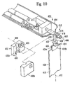
- Figure 10 shows a mini-blind actuator, generally designated 400, that is used to rotate a rod 402 that is rotatably mounted in an elongated head rail 404 of a so-called vertical blind 406. It is to be understood that the actuator 400 is in all essential respects identical with the actuator 300 shown in Figures 8 and 9.
- the rod 402 defines a first axis of rotation 408, and a plurality of elongated slats (only a single slat 410 shown in Figure 10 for clarity of disclosure) are connected to the rod 402.
- the slat 410 defines a second axis of rotation 412 which is oriented substantially perpendicularly to the first axis of rotation 408.
- rotation of the rod 402 about the first axis 408 causes rotation of the slat 410 about the second axis 412.
- the head rail 404 and rod 402 define a long axis 408, and the slat 410 defines a long axis 412, with the slat 410 depending downwardly from the head rail 404 such that the long axis 412 of the slat 410 is perpendicular to the long axis 408 of the head rail 404 and rod 402.
- Figure 10 shows that the slat 410 is connected to the rod 402 via a connector, generally designated 414.
- the connector 414 includes a hollow rod element 416 which is surroundingly engaged with the rod 402 in a close fit therewith, such that the rod element 416 can slide on the rod 402 but cannot rotate relative to the rod 402. Consequently, rotation of the rod 402 causes rotation of the rod element 416 about the first axis of rotation 408.
- the rod element 416 is formed with a bore which is configured substantially identically to the radial cross-sectional configuration, e.g., hexagonal as shown, of the rod 402.
- rotation between the rod 402 and rod element 416 can be prevented by other means, e.g., a set screw (not shown).
- Figure 10 shows that the rod element 416 is formed with an outer raised helical surface 418.
- the helical surface 418 "travels" longitudinally with respect to the rod 402.
- the connector 414 includes a slat element 420 that is formed with a plurality of channels 422. As shown, each channel 422 is oriented perpendicularly to the first axis of rotation 408. As further shown, at least one channel 422 is threadably engaged with the helical surface 418 of the rod element 416. Moreover, the slat element 420 is formed with a clip segment 424.
- the clip segment 424 includes left and right co-parallel parallelepiped-shaped clip plates 424a, 424b which define a slot 426 therebetween, and the slat 410 is fixedly held within the slot 426 by, e.g., a close interference fit or a solvent bond. Consequently, rotation of the rod element 416 about the first axis of rotation 408 causes rotation of the slat element 420 and, hence, slat 410, about the second axis of rotation 412.
- a disc-shaped collar 428 is formed on the slat element 420.
- the collar 428 engages a groove 430 that is formed in a two-piece molded connector housing 432. having halves 432a, 432b to support the slat element 420 and hold the slat element 420 in threadable engagement with the rod element 416.
- each half 432a, 432b of the connector housing 432 is configured with a hole 433 that slidably engages the rod 402, and the connector housing 432 encloses and supports the connector 414.
- the blind 406 includes a plurality of slats, each of which is substantially identical in configuration and operation with the slat 410 with connector 414.
- the switch of the present invention i.e., the first trigger 142 or transistor Q2
- receives a control signal from the sensors 28, 29, respectively and then activates the electronic circuit in response thereto to permit the circuit to cause the power supply 42 to energize the motor 60.
- the electronic circuit is deactivated in the absence of the control signal.
- the circuit shown in Figure 9 is deactivated in the absence of the control signal.
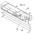
- FIG 11 shows a mini-blind actuator, generally designated 500, that is used to rotate a shaft-like rod 502 that is rotatably mounted in an elongated head rail 504 of a so-called pleated or cellular shade 506.
- the shade 506 is an accordion-type window covering, i.e., the shade 506 compressively accordions upwardly to a raised configuration and expansively accordions downwardly to a lowered configuration.
- the rod 502 is keyed to a capstan 507 for rotating the capstan 507 while permitting slidable motion of the capstan 507 relative to the rod 502.
- U.S. Patent No. 4,623,012 to Rude et al. incorporated herein by reference, discloses one acceptable shaft-capstan arrangement for use with pleated shades.
- actuator 500 is in all essential respects identical with the actuator 300 shown in Figures 8 and 9.
- the shade 506 includes a plurality of elongated sections 508 that are joined at their respective left and right edges 510, 512. As shown, the sections 508 are horizontally mounted, i.e., the long axes of the sections 508 are parallel to the long axis 514 of the head rail 504. A drawstring 516 is partially wound around the capstan 507 and is engaged by means well-known in the art to at least a bottom-most section 508a.
- the actuator 500 can be actuated to rotate the rod 502 and capstan 507 and thereby raise or lower the bottom-most section 508a of the shade 506 relative to the head rail 504.
- the rod 502 can be rotated to cause the bottom-most section 508a to move translationally relative to the head rail 504, with the bottom-most section 508a (and, indeed, the remaining sections 508) staying parallel to the head rail 504 during the raising and lowering process.
Abstract
Description
- The present application is a continuation-in-part of and claims priority from the following co-pending U.S. patent applications: Serial No. 08/076,556 for an invention entitled "Mini-Blind Actuator" filed June 11, 1993; and Serial No. 08/094,570 for an invention entitled "Head Rail-Mounted Mini-Blind Actuator" filed July 20, 1993, both assigned to the same assignee as the present invention.
- The present invention relates generally to window covering peripherals and more particularly to remotely-controlled mini-blind actuators.
- Louvered blinds, such as LevellorR mini-blinds, are used as window coverings in a vast number of business buildings and dwellings. The typical blind has a number of horizontal elongated parallelepiped-shaped louvers, i.e., rotationally-movable slats, which are collectively oriented with their major surfaces parallel to the ground ("open") to permit light to pass between adjacent slats, or with their major surfaces perpendicular to the ground ("closed"), to block light from passing between adjacent slats, or any intermediate position between open and closed. Stated differently, the slats can be rotated about their respective longitudinal axes, i.e., about respective lines which are parallel to the ground, to open or close the blind. Alternatively, the slats may be oriented vertically for rotation about their respective longitudinal axes (i.e., for rotation about respective lines that are perpendicular to the ground), for opening and closing the blind.
- Ordinarily, to provide for movement of the slats of a blind between the open and closed positions, an elongated actuating baton is coupled to structure on the blind such that when the baton is manually rotated about its longitudinal axis, the slats move in unison between the open and closed positions. It will accordingly be appreciated that by proper manual operation of the baton, blinds can be used to effectively regulate the amount of light which passes into the room in which the blind is located. Thus, blinds can be opened during the day to permit sunlight to enter the room, or closed during particularly warm days to prevent overheating of the room. Likewise, blinds can be closed at night for security purposes, and to prevent heat within the room from dissipating through the window into the cool evening air.
- While most existing manually-operated blinds accordingly provide an effective means for regulating the amount of light propagating into or out of a room, it is often advantageous to provide for remote or automatic positioning of the blinds. For example, it would be advantageous to provide for the automatic nighttime closing of blinds in a business premises, for both security reasons and energy conservation, rather than to rely on personnel to remember to manually close all blinds before vacating the premises for the evening. Also, remote operation of blinds would enable many invalid persons to regulate the amount of light entering their rooms, without requiring the persons to manually operate the actuating baton.
- Not surprisingly, several systems have been introduced for either lowering and raising the slats of a blind, or for moving the slats between the open and closed positions. For example, U.S. Patent No. 4,644,990 to Webb, Sr. et al. teaches a system for automatically moving a set of venetian-type window blinds in response to sensing a predetermined level of sunlight. Likewise, U.S. Patent No. 3,860,055 to Wild teaches a system for automatically raising or lowering a shutter upon sensing a predetermined level of sunlight. Also, U.S. Patent No. 4,096,903 to Ringle, III discloses a system for opening a blind, wherein the Ringle, m system is mounted in the head rail of the blind and operates the blind in response to an electromagnetic control signal. The document JP 61-109890 discloses a blind opening and closing system for use with venitian type blinds. It has a drive circuit which is alleged to control the driving of a DC motor, which is powered by a dry cell.
- Unfortunately, the systems mentioned above, like many, if not most, automatic blind control systems, are somewhat complicated in operation and cumbersome and bulky in installation, and consequently are relatively expensive. For example, the Webb, Sr. et al. system requires that a housing be mated with the blind structure for holding the various components of the patented system, which includes, inter alia, ratchets, pawls, gears, clutches, levers, and springs. In a similar vein, the Wild invention requires the use of, among other components, a rather bulky gas-driven piston-and-cylinder to raise and lower the shutter. Precisely how the piston-and-cylinder is mounted on an existing shutter assembly is not discussed by Wild. The Ringle, III device consumes a relatively large amount of power to sense its control signal, and thus exhausts its battery quickly, in part because of its relatively complicated limit switch mechanism and because Ringle, III does not provide any electronic signal processing which would enable the Ringle, III device to sense a control signal efficiently, with little power consumption.
- Accordingly, it is an object of the present invention to provide a comparatively simple device for opening and closing blinds, in particular pleated or cellular, or accordion-type shades, or shades having vertical slats. It is another object of the present invention to provide a remote control device for opening and closing blinds which is compact and easy to install. Yet another object of the present invention is to provide a device for remotely and automatically opening and closing blinds. Still another object of the present invention is to provide a device for remotely and automatically opening and closing mini-blinds which consumes relatively little power. Further, it is an object of the present invention to provide a device for remotely and automatically opening and closing blinds which is easy to use and cost-effective to manufacture.
- Two embodiments of the actuator according to the invention are defined by claims 1 and 2.
- Several other embodiments are defined by dependent claims 3 to 11.
- The details of the present invention, both as to its construction and operation, can best be understood in reference to the accompanying drawings, in which like numerals refer to like parts. Figures 1 to 7 of the drawings illustrate an actuator for rotating an actuating baton of a blind which is described and claimed in European Patent No. 0702855 (Patent Application No. 94920290.7). Figures 8 and 9 illustrate a window blind actuator as described and claimed in European Patent No. (Patent Application No. 94919344.5). Because many of the component parts and the mode of operation of the actuator described in relation to those Figures are similar to the actuator of the present invention, Figures 1 to 9 and the related description are included herein as an aid to the understanding of the claimed invention.
-
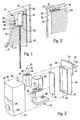
- Figure 1 is a perspective view of the actuator of the present invention, shown in one intended environment;
- Figure 2 is another perspective view of the actuator of the present invention, shown in one intended environment;
- Figure 3 is an exploded view of the actuator of the present invention;
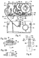
- Figure 4 is a perspective view of the gear assembly of the actuator of the present invention, with portions broken away;
- Figure 5A is a perspective view of the main reduction gear of the actuator of the present invention;
- Figure 5B is a cross-sectional view of the main reduction gear of the actuator of the present invention, as seen along the
line 5B-5B in Figure 5A; - Figure 6 is a perspective view of the reed switch of the actuator of the present invention;
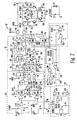
- Figure 7 is a schematic diagram of the electronic circuitry of the actuator of the present invention;
- Figure 8 is a perspective view of an alternate embodiment of the blind actuator present invention, with portions of the head rail of the blind cut away for clarity;
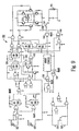
- Figure 9 is a schematic diagram of the electronic circuitry of the actuator shown in Figure 8;
- Figure 10 is a partially exploded perspective view of still another alternate embodiment of the blind actuator present invention in conjunction with a vertical blind, with portions of the head rail of the blind cut away for clarity; and
- Figure 11 is a perspective view of another alternate embodiment of the blind actuator present invention in conjunction with a pleated shade, with portions of the head rail of the blind cut away for clarity.
- Referring initially to Figure 1, an actuator is shown, generally designated 10. As shown, the
actuator 10 is in operable engagement with arotatable operating baton 12 of a mini-blind 14 having a plurality oflouvered slats 16. - In the embodiment shown, the mini-blind 14 is a LevellorR-type mini-blind which is mounted on a
window frame 18 to cover awindow 20, and thebaton 12 is rotatable about its longitudinal axis. When thebaton 12 is rotated about its longitudinal axis, each of theslats 16 is caused to rotate about its respective longitudinal axis to move the mini-blind 14 between an open configuration, wherein a light passageway is established between each pair of adjacent slats, and a closed configuration, wherein no light passageways are established between adjacent slats. - While the embodiment described above discusses a mini-blind, it is to be understood that the principles of the present invention apply to a wide range of window coverings that have louvered slats.
- As can be appreciated in reference to Figure 1, the
baton 12 has a hexagonally-shaped transverse cross-section, and thebaton 12 is slidably engageable with achannel 22 of theactuator 10. Accordingly, theactuator 10 can be slidably engaged with thebaton 12 substantially anywhere along the length of thebaton 12. - Figure 2 shows that the
actuator 10 includes a fastening element, preferably aclip 23, for fastening theactuator 10 to ahead rail 24 of the mini-blind 14. In the embodiment shown, theclip 23 engages thehead rail 24 in a close interference fit to hold theactuator 10 onto thehead rail 24. Asupport 25 is connected to or molded integrally with theactuator 10, and thesupport 25 extends below thehead rail 24 and above thetop slat 16a of the blind 14 to laterally support theactuator 10. - Alternatively, the
actuator 10 can be fastened to thewindow frame 18. In such an embodiment, a strip of tape (not shown) having adhesive material on both of its opposed major surfaces is adhered to a portion of theactuator 10, and when theactuator 10 is gently pressed against thewindow frame 18, the tape adheres to thewindow frame 18 to fasten theactuator 10 to thewindow frame 18. It is to be understood that theactuator 10 alternatively may be attached to theframe 18 by bolts, screws, glue, nails, or other well-known fasteners. - In cross-reference to Figures 2 and 3, the
actuator 10 has a rigid solid plasticlight pipe 26 which, when theactuator 10 is mounted on thewindow frame 18 as shown, extends between thewindow 20 and the mini-blind 14. Accordingly, a light passageway is established by thelight pipe 26 from thewindow 20 to theactuator 10. To facilitate the transmission of light through thelight pipe 26, thelight pipe 26 has anend 27 which has a relatively rough, e.g., thirty micron (30µ) finish, while the remainder of the surface of thelight pipe 26 has a three micron (3µ) finish. It will be appreciated in reference to Figures 1 and 2 that thelight pipe 26 also provides lateral support to theactuator 10, in the same manner as provided by thesupport 25. - A control signal generator, preferably a daylight sensor 28 (shown in phantom in Figure 3) is mounted on the
actuator 10 by means well-known in the art, e.g., solvent bonding. In accordance with the present invention, thedaylight sensor 28 is in light communication with thelight guide 26. Also, thesensor 28 is electrically connected to electronic components within theactuator 10 to send a control signal to the components, as more fully disclosed below. Consequently, with the arrangement shown, thedaylight sensor 28 can detect light that propagates through thewindow 20, independent of whether the mini-blind 14 is in the open configuration or the closed configuration. - Further, the
actuator 10 includes another control signal generator, preferably asignal sensor 29, for receiving an optical, preferably visible red modulated user command signal. Preferably, the user command signal is generated by a hand-held usercommand signal generator 31, which advantageously is a television remote-control unit. In one presently preferred embodiment, thegenerator 31 generates a pulsed optical signal having a pulse rate of between about fifteen hundred microseconds and five thousand microseconds (1500µs-5000µs). - Like the
daylight sensor 28, thesignal sensor 29 is electrically connected to electronic components within theactuator 10. As discussed in greater detail below, either one of thedaylight sensor 28 andsignal sensor 29 can generate an electrical control signal to activate theactuator 10 and thereby cause the mini-blind 14 to move toward the open or closed configuration, as appropriate. - Preferably, both the
daylight sensor 28 andsignal sensor 29 are light detectors which have low dark currents, to conserve power when theactuator 10 is deactivated. More particularly, thesensors daylight sensor 28 andsignal sensor 29 are selected double-end type phototransistors made by Sharp Electronics, part no. PT 460. - Referring now to Figure 3, the
actuator 10 includes a hollow, generally parallelepiped-shaped lightweight metal or moldedplastic clamshell housing 30. As shown, thehousing 30 has afirst half 32 which is snappingly engageable with asecond half 34. Alternatively, thefirst half 32 of thehousing 30 can be glued or bolted to thesecond half 34. Twoopenings housing 30 to establish thechannel 22 shown in Figure 1. As also shown in Figures 1 and 3, thehousing 30 has a slightly convexfront surface 39. - As shown best in Figure 3, a molded
plastic battery carriage 40 is positioned within thehousing 30. Preferably, thebattery carriage 40 generally conforms to the inside contour of thehousing 30, i.e., thehousing 30 "captures" thebattery carriage 40 and holds thecarriage 40 stationary within thehousing 30. - A
power supply 42 is mounted in thebattery carriage 40. In the preferred embodiment, thepower supply 42 includes four type AA direct current (dc)alkaline batteries batteries battery carriage 40 in electrical series with each other by means well-known in the art. For example, in the embodiment shown, each of thebatteries negative metal clips 45 to hold thebatteries carriage 40 and to establish an electrical path between thebatteries - Figure 3 further shows that an
electronic circuit board 52 is positioned in thehousing 30 adjacent thebattery carriage 40. It is to be understood that an electrical path is established between the battery clips and the electronic circuit board. Consequently, thebatteries electronic circuit board 52. The electronic components of thecircuit board 52 are discussed in more detail in reference to Figure 7 below. - Still referring to Figure 3, a lightweight metal or molded
plastic gear box 56 is attached to or formed integrally with thebattery carriage 40. Thegear box 56 is formed with agear box opening 58 for receiving thebaton 12 therein. - Figure 3 also shows that a small, lightweight
electric motor 60 is attached to thegear box 56, preferably by bolting themotor 60 to thegear box 56. In the presently preferred embodiment, themotor 60 is a direct current (dc) motor, type FC-130-10300, made by Mabuchi Motor America Corp. of New York. As more fully disclosed in reference to Figure 4 below, thegear box 56 holds a gear assembly which causes thebaton 12 to rotate at a fraction of the angular velocity of themotor 60. As further discussed below more fully in reference to Figure 7, themotor 60 can be energized by thepower supply 42 through thecircuit board 52. - Now referring to Figures 4, 5A, 5B, and 6, the details of the
gear box 56 can be seen. As shown best in Figure 4, thegear box 56 includes a plurality of lightweight metal or molded plastic gears, i.e., a gear assembly, and each gear is rotatably mounted within thegear box 56. In the presently preferred embodiment, thegear box 56 is a clamshell structure which includes afirst half 62 and asecond half 64, and thehalves gear box 56 are snappingly engageable together by means well-known in the art. For example, in the embodiment shown, apost 66 in thesecond half 64 of thegear box 56 engages ahole 68 in thefirst half 62 of thegear box 56 in an interference fit to hold thehalves - Each
half respective opening openings gear box 56 establish the gear box opening 58 (Figure 3) and are coaxial with thechannel 22 of thehousing 30 for slidably receiving thebaton 12 therethrough. - As shown in Figure 4, a
motor gear 74 is connected to therotor 76 of themotor 60. In turn, themotor gear 74 is engaged with afirst reduction gear 78, and thefirst reduction gear 78 is engaged with asecond reduction gear 80. - As shown in Figure 4, the
second reduction gear 80 is engaged with amain reduction gear 82. To closely receive a hexagonally-shaped baton, themain reduction gear 82 has a hexagonally-shapedchannel 84. As intended by the present invention, thechannel 84 of themain reduction gear 82 is coaxial with theopenings 70, 72 (and, thus, with thegear box opening 58 of thegear box 56 shown in Figure 3). Consequently, thechannel 84 of themain reduction gear 82 is also coaxial with thechannel 22 of thehousing 30, for receiving thebaton 12 therethrough. - It can be appreciated in reference to Figure 4 that when the
main reduction gear 82 is rotated, and thebaton 12 is engaged with thechannel 84 of themain reduction gear 82, the sides of thechannel 84 contact thebaton 12 to prevent rotational relative motion between thebaton 12 and themain reduction gear 82. Further, the reduction gears 78, 80, 82 cause thebaton 12 to rotate at a fraction of the angular velocity of themotor 60. Preferably, the reduction gears 78, 80, 82 reduce the angular velocity of themotor 60 such that thebaton 12 rotates at about one revolution per second. - It is to be understood that the
channel 84 of themain reduction gear 82 can have other shapes suitable for conforming to the shape of the particular baton being used. For example, for a baton (not shown) having a circular transverse cross-sectional shapes, thechannel 84 will have a circular cross-section. In such an embodiment, a set screw (not shown) is threadably engaged with themain reduction gear 82 for extending into thechannel 84 to abut the baton and hold the baton stationary within thechannel 84. In other words, thegears motor 60 with thebaton 12. - In cross-reference to Figures 4, 5A, and 5B, the
main reduction gear 82 is formed on ahollow shaft 86, and theshaft 86 is closely received within theopening 70 of thefirst half 62 of thegear box 56 for rotatable motion therein. Also, a first travellimit reduction gear 88 is formed on theshaft 86 of themain reduction gear 82. The first travellimit reduction gear 88 is engaged with a second travellimit reduction gear 90, and the second travellimit reduction gear 90 is in turn engaged with a third travel limit reduction gear 92. - Figure 4 best shows that the third travel limit reduction gear 92 is engaged with a linear rack gear 94. Thus, the
main reduction gear 82 is coupled to the rack gear 94 through the travel limit reduction gears 88, 90, 92, and the rotational speed (i.e., angular velocity) of themain reduction gear 82 is reduced through the first, second, and third travel limit reduction gears 88, 90, 92. Also, the rotational motion of themain reduction gear 82 is translated into linear motion by the operation of the third travel limit reduction gear 92 and rack gear 94. - Figure 4 shows that the
second reduction gear 80 and second and third travel limit reduction gears 90, 92 are rotatably engaged with respectivemetal post axles first half 62 of thegear box 56. In contrast, thefirst reduction gear 78 is rotatably engaged with ametal post axle 78a which is anchored in thesecond half 64 of thegear box 56. - Still referring to Figure 4, the rack gear 94 is slidably engaged with a
groove 96 that is formed in thefirst half 62 of thegear box 56. First andsecond travel limiters travel limiters - As yet another alternative, travel limiters (not shown) may be provided which are formed with respective detents (not shown). In such an embodiment, the rack gear is formed with a channel having a series of openings for receiving the detents, and the travel limiters can be manipulated to engage their detents with a preselected pair of the openings in the rack gear channel. In any case, it will be appreciated that the position of the travel limiters of the present invention relative to the rack gear 94 may be manually adjusted.
- Figure 4 shows that each
travel limiter respective abutment surface 102, 104. In cross-reference to Figures 4 and 6, the abutment surfaces 102, 104 can contact areed switch 106 which is mounted on abase 107. Thebase 107 is in turn anchored on thesecond half 64 of thegear box 56. As intended by the present invention, thereed switch 106 includes electrically conductive, preferably beryllium-copper first andsecond spring arms copper center arm 110. As shown, one end of eachspring arm base 107, and the opposite ends of thespring arms base 107. As also shown, one end of thecenter arm 110 is attached to thebase 107. - When the
main reduction gear 82 has rotated sufficiently counterclockwise, the abutment surface 102 of thefirst travel limiter 98 contacts thefirst spring arm 108 of thereed switch 106 to urge thefirst spring arm 108 against thestationary center arm 110 of thereed switch 106. On the other hand, when themain reduction gear 82 has rotated clockwise a sufficient amount, theabutment surface 104 of thesecond travel limiter 100 contacts thesecond spring arm 112 of thereed switch 106 to urge thesecond spring arm 112 against thestationary center arm 110 of thereed switch 106. - Figure 6 best shows that an electrically conductive, preferably gold-plated
contact 114 is deposited on thefirst spring arm 108, and electrically conductive, preferably gold-platedcontacts center arm 110. Also, an electrically conductive, preferably gold-platedcontact 118 is deposited on thesecond spring arm 112. - Thus, when the
first spring arm 108 is urged against thecenter arm 110, thecontact 114 of thefirst spring arm 108 contacts thecontact 116a of thecenter arm 110 to complete an electrical circuit. On the other hand, when thesecond spring arm 112 is urged against thecenter arm 110, thecontact 118 of thesecond spring arm 112 contacts thecontact 116b of thecenter arm 110 to complete an electrical circuit. It can be appreciated in reference to Figure 4 that thereed switch 106 is electrically connected to the circuit board 52 (Figure 3) via anelectrical lead 119. - As more fully disclosed below in reference to Figure 7, the completion of either one of the electrical circuits discussed above causes the
motor 60 to deenergize and consequently stops the rotation of themain reduction gear 82 and, hence, the rotation thebaton 12. Stated differently, thetravel limiters baton 12 by theactuator 10. - Referring briefly back to Figure 4,
spacers halves halves gear box 56 are snapped together. - Now referring to Figure 7, the details of the electrical circuitry contained on the
circuit board 52 may be seen. In overview, theelectrical circuit board 52 includes apulse modulation detector 130 and a beam andmanual direction controller 132 for processing the user command signal generated by the usercommand signal generator 31 and sensed by the signal sensor 29 (Figure 1) for opening and closing the blind 14. Also, to operate the blind 14 in response to a predetermined level of sunlight as sensed by the daylight sensor 28 (Figure 3), thecircuit board 52 includes adaylight detector 134, adaylight direction controller 136, and anedge detector 138. Theedge detector 138 prevents operation of the blind 14 in response to spurious light signals, e.g., automobile headlights. Additionally, thecircuit board 52 has anoutput amplifier 140 for powering themotor 60 shown in Figure 3. - For clarity of disclosure, the discussion below focusses on the salient components of the
electrical circuit board 52. Table 1 below, however, sets forth the values of all of the resistors and capacitors of thecircuit board 52 of the preferred embodiment. - Figure 7 shows that the
pulse modulation detector 130 includes a switch, preferably a first type 4093Schmidt trigger 142 that is electrically connected to thesignal sensor 29 for receiving the pulse modulated detection signal therefrom. From thefirst trigger 142, the signal is sent to first andsecond stages NAND gate inverter 148. TheNAND gate inverter 148 functions as an inverter, generating a FALSE signal output signal from two TRUE input signals and a TRUE signal output otherwise. From theNAND gate inverter 148, the signal is sent through a firsttype 1N4148 diode 150 to a capacitor C2. Also, from thesecond stage 146, the signal is sent through a secondtype 1N4148 diode 152 to a capacitor C8. - When the
first trigger 142 senses a pulsed optical signal from thesignal sensor 29, thefirst trigger 142 generates an output signal having the same pulse rate as the optical signal from thesignal sensor 29. When the output signal of thetrigger 142 has a pulse rate greater than 5000µs, the output signal of thefirst stage 144 is FALSE. Consequently, the output of theNAND gate inverter 148 is TRUE. A TRUE output signal from theNAND gate inverter 148 maintains a positive voltage on the capacitor C2. As more fully discussed below, when a positive voltage is maintained on the capacitor C2, energization of themotor 60 is prevented. - Additionally, when the output signal of the
first trigger 142 has a pulse rate less than fifteen thousand microseconds (1500µs), the output signal of thesecond stage 146 will be FALSE. Consequently, the capacitor C8 discharges, which causes the input signal of theNAND gate inverter 148 from thesecond stage 146 to become FALSE. In response, the output of theNAND gate inverter 148 is TRUE, which, as discussed above, maintains a positive voltage on the capacitor C2 to prevent energization of themotor 60. - In contrast, when the output signal of the
first trigger 142 has a pulse rate between fifteen hundred microseconds and five thousand microseconds (1500µs-5000µs) (indicating reception by thesignal sensor 29 of a proper optical control signal having a pulse rate of between 1500µs-5000µs), the output signals of both the first andsecond stages NAND gate inverter 148 is FALSE, permitting the capacitor C2 to discharge and thereby permit energization of themotor 60. - The skilled artisan will appreciate that the values of R2 and C2 are selected to require that the output signal of the first
NAND gate inverter 148 remains FALSE for at least three hundred thirty milliseconds (330ms) before the capacitor C2 fully discharges to enable energization of themotor 60. The skilled artisan will further appreciate that when a two-position switch 154 having an "ON" position and an "OFF" position (Figures 1 and 7) is manually moved to the "OFF" position, voltage from thepower supply 42 is conducted to the capacitor C2 to prevent the automatic energization of themotor 60 described above. Themotor 60 may nevertheless be energized when the two-position switch 154 is in the "OFF" position, however, by manually depressing a thumbswitch 156 (Figures 1 and 7), as more fully disclosed below. - Figure 7 shows that the beam and
manual direction controller 132 includes a second type 4093NAND gate inverter 158, the input signal of which is the output signal of the firstNAND gate inverter 148. Upon receipt of a "FALSE" input signal from the first NAND gate inverter 148 (indicating reception by thesignal sensor 29 of a proper optical control signal having a pulse rate of between 1500µs-5000µs for at least 330ms), the secondNAND gate inverter 158 generates an output clocking signal. Also, Figure 7 shows that when thethumbswitch 156 is depressed, a "FALSE" input signal is sent to the secondNAND gate inverter 158, and an output clocking signal is consequently generated by theinverter 158. - The output clocking signal of the second
NAND gate inverter 158 is sent in turn to a type 4013 "D" motor run flip-flop 160. As shown in Figure 7, the flip-flop 160 is in the so-called "toggle" configuration (i.e., pin 2 of the flip-flop 160 is electrically connected to its pin 5). Accordingly, the flip-flop 160 changes state each time it receives a clocking signal. - Figure 7 shows that the motor run flip-
flop 160 is electrically connected to a type 4013 "D" motor direction flip-flop 162. Like the motor run flip-flop 160, the motor direction flip-flop 162 is in the "toggle" configuration. - In accordance with the present invention, the motor run flip-
flop 160 generates either a "motor run" or "motor stop" output signal, while the motor direction flip-flop 162 generates either a "clockwise" or "counterclockwise" output signal. As discussed above, each time the motor run flip-flop 160 receives a clocking signal, it changes state. Also, each time the motor run flip-flop 160 is reset to a "stop motor" state, it toggles the motor direction flip-flop 162 via a line 163 to change state. - Thus, with the motor direction flip-flop 162 initially in the clockwise state, to cause the motor run flip-
flop 160 to generate a "motor run" output signal, the user signal generator 31 (Figure 1) is manipulated to generate a first user command signal (or thethumbswitch 156 is depressed). Then, to cause the motor run flip-flop 160 to generate a "motor stop" output signal, theuser signal generator 31 is manipulated to generate a second user command signal (or thethumbswitch 156 is again depressed). - Upon receiving the second clocking signal, the motor run flip-
flop 160 toggles the motor direction flip-flop 162 to change state (i.e., to counterclockwise). Then, manipulation of theuser signal generator 31 to generate yet a third user command signal (or again depressing the thumbswitch 156) causes the motor run flip-flop to generate a "motor run" signal. Yet a fourth signal causes themotor 60 to again stop, and so on. - Additionally, the state of the motor run flip-
flop 160 is caused to change when themotor 60 reaches its predetermined clockwise or counterclockwise limits of travel, as established by the positions of thetravel limiters motor 60 after themotor 60 has reached a travel limit, as sensed by thereed switch 106. - In describing this means of changing the state of the motor run flip-
flop 160 in response to travel motion limitations, the motor direction flip-flop 162 generates either a clockwise ("CW") output signal or a counterclockwise ("CCW") output signal, as mentioned above and indicated in Figure 7 by lines CW and CCW. In the presently preferred embodiment, clockwise rotation of themotor 60 corresponds to opening the blind 14, while counterclockwise rotation of themotor 60 corresponds to closing, i.e., shutting, the blind 14. - In further disclosing the cooperation of the motor direction flip-flop 162 with the motor run flip-
flop 160, the "CW" output signal of the motor direction flip-flop 162 is sent to a first type 4093 limit switch NAND gate 164, whereas the "CCW" output signal of the motor direction flip-flop 162 is sent to a second type 4093 limit switch NAND gate 166. The output signals of the first and second limit switch NAND gates 164, 166 are sent in turn to a third type 4093 limit switch NAND gate 168, and the output signal of the third limit switch NAND gate 168 is sent to the motor run flip-flop 160. - Figure 7 also shows that the first and second limit switch NAND gates 164, 166 receive respective upper limit reached ("USW") and lower limit reached ("LSW") input signals. As shown in Figure 7, the "USW" signal is generated by a type 4093
USW NAND gate 170, and the "LSW" signal is generated by a type 4093LSW NAND gate 172. - Both
NAND gates direction NAND gate 174. In turn, thedirection NAND gate 174 receives an input signal indicating the direction of actual rotation of the motor 60 (i.e., the "motor run CW" signal or the "motor run CCW" signal. In Figure 7, the "motor run CW" signal has been designated "DRCW", and the "motor run CCW" signal has been designated "DRCCW", and the generation of both the "DRCW" and "DRCCW" signals is discussed more fully below. - The output signal of the
direction NAND gate 174 is always "TRUE", unless it senses that themotor 60 has been simultaneously given both a "motor run CW" ("DRCW") signal and a "motor run CCW" ("DRCCW") signal, in which case the output signal of the direction NAND gate is "FALSE". Thus, the "DRCCW" and "DRCW" signals are gated as described above to prevent damaging theoutput amplifier 140 if themotor 60 is erroneously commanded to simultaneously rotate in both the clockwise and counterclockwise directions. - Additionally, the
USW NAND gate 170 receives an input signal from thereed switch 106 when the abutment surface 102 of the travel limiter 98 (Figure 4) urges thefirst arm 108 against thecenter arm 110 of theswitch 106, indicating that the rack gear 94 (and, hence, the motor 60) has reached the predetermined upper, i.e., clockwise, limit of travel. Also, theLSW NAND gate 172 receives an input signal from thereed switch 106 when theabutment surface 104 of the travel limiter 100 (Figure 4) urges thesecond arm 112 against thecenter arm 110 of theswitch 106, indicating that the rack gear 94 (and, hence, the motor 60) has reached the predetermined lower, i.e., counterclockwise, limit of travel. - Accordingly, upon receipt of the appropriate signal from the
reed switch 106, theUSW NAND gate 170 generates the USW signal. Likewise, upon receipt of the appropriate signal from thereed switch 106, theLSW NAND gate 172 generates the LSW signal. - Further, independent of the position of the
reed switch 106, in the event that the output signal of thedirection NAND gate 174 is "FALSE", theUSW NAND gate 170 generates a USW signal, and theLSW NAND gate 172 generates a LSW signal. Consequently, themotor 60 will be caused to stop if thedirection NAND gate 174 senses the simultaneous existence of both a "motor run CW" (i.e., a "DRCW") signal and a "motor run CCW" (i.e., a "DRCCW") signal. - As discussed above, the LSW and USW signals are sent to the first and second limit switch NAND gates 164, 166, which generate input signals to the third limit switch NAND gate 168. In turn, the third limit switch NAND gate 168 sends a clocking signal to the motor run flip-
flop 160 to cause the motor run flip-flop 160 to change state, i.e., to the "motor off" state. - Accordingly, when the
motor 60 is rotating clockwise and the upper (i.e., clockwise) limit of rotation is reached, thereed switch 106 generates a signal which is sent via the following path to change the state of the motor run flip-flop 160 to cause themotor 60 to stop:USW NAND gate 170, first limit switch NAND gate 164, third limit switch NAND gate 168. - Likewise, when the
motor 60 is rotating counterclockwise and the lower (i.e., counterclockwise) limit of rotation is reached, thereed switch 106 generates a signal which is sent via the following path to change the state of the motor run flip-flop 160 to cause themotor 60 to stop:LSW NAND gate 172, second limit switch NAND gate 166, third limit switch NAND gate 168. - Figure 7 additionally shows that the "USW" and "LSW" signals are also sent to the motor direction flip-flop 162 via respective resistors R22, R23 to reset the flip-flop 162 to the appropriate state. Stated differently, the "USW" signal is sent to the motor direction flip-flop 162 via resistor R22 to reset the flip-flop 162 to the counterclockwise state, and the "LSW" signal is sent to the motor direction flip-flop 162 via resistor R23 to reset the flip-flop 162 to the clockwise state, when the appropriate travel limits have been reached.
- The output signals of the flip-
flops 160, 162 are each gated to type 4093 flip-flop CW andCCW NAND gates 176, 178. More specifically, both output signals of the motor run flip-flop 160 are gated to theNAND gates 176, 178, whereas only the "CW" output signal of the motor direction flip-flop 162 is gated to theCW NAND gate 176, and the "CCW" signal from the motor direction flip-flop 162 is gated to the CCW NAND gate 178. - As intended by the present invention, the flip-flop
CW NAND gate 176 generates a "motor run CW" (i.e., the "DRCW") output signal only when the motor run flip-flop 160 inputs a "motor run" signal to theCW NAND gate 176 and the motor direction flip-flop 162 inputs a "CW" signal to theNAND gate 176. Likewise, the flip-flop CCW NAND gate 178 generates a "motor run CCW" (i.e., "DRCCW") output signal only when the motor run flip-flop 160 inputs a "motor run" signal to the CCW NAND gate 178 and the motor direction flip-flop 162 inputs a "CCW" signal to the NAND gate 178. - Now referring to the
daylight detector 134 shown in Figure 7, the purpose of which is to energize themotor 60 to open or close the blind 14 upon detection of a predetermined level of light that is present at thedaylight sensor 28, thedaylight sensor 28 is electrically connected to a switch, preferably a first type 2N3904 transistor Q2. Accordingly, when light impinges upon thedaylight sensor 28, thesensor 28 sends a signal to the transistor Q2. - If desired, energization of the
motor 60 in response to signals generated by thedaylight sensor 28 can be disabled by appropriately manipulating a two-position daylight disableswitch 180. Theswitch 180 has an "AUTO" position, wherein automatic operation of theactuator 10 in response to signals from thedaylight sensor 28 is enabled, and an "OFF" position, wherein automatic operation of theactuator 10 in response to signals from thedaylight sensor 28 is disabled. - After receiving the signal from the
daylight sensor 28, the first transistor Q2 turns on, and consequently causes a first type 2N3906 transistor Q1 to turn on. The output signal of the second transistor Q1 is sent via a resistor R4 to the base of the first transistor Q2, to establish a hysterisis-based electronic signal latch. Also, the output signal of the second transistor Q1 is sent to a type 4093 light NAND gate 182. Whenever the light NAND gate 182 receives a signal from the second transistor Q1, the NAND gate 182 changes state. - Figure 7 shows that the output signal generated by the light NAND gate inverter 182 is sent to the so-called "D" input ports of type 4013 first and
second stages daylight direction controller 136. The output signals of thestages gate motor controllers output amplifier circuitry 140. - To generate their motor run output signals, the
stages daylight direction controller 136 must also receive input signals from theedge detector 138. As intended by the present invention, theedge detector 138 functions to prevent automatic operation of the blind 14 in the presence of detection signals generated by thedaylight detector 136 in response to spurious light signals, e.g., automobile headlights at night. - Figure 7 shows that the
edge detector 138 includes a type 4077 exclusive NOR gate 194. As shown, the exclusive NOR gate 194 receives a first input signal directly from the light NAND gate 182 and a second input signal which originates at the NAND gate 182 and which is passed through the network established by a resistor R13 and a capacitor C4. With this arrangement, the exclusive NOR gate 194 generates a positive pulse output signal each time the light NAND gate 182 changes state. - As further shown in Figure 7, the output signal of the exclusive NOR gate 194 is sent to a type 4020 fourteen (14)
stage binary counter 196. Thecounter 196 is associated with anoscillator 198 that includes a type 4093NAND gate 199, and the counter is also associated with first and second type 4077 exclusive NORgate inverters gate inverters - As disclosed above, when a detection signal is received from the light NAND gate 182 of the
daylight detector 134, this signal is sent to the exclusive NOR gate 194 in theedge detector 138 and to the first andsecond stages daylight direction controller 136. The first andsecond stages - Instead, the exclusive NOR gate 194 immediately sends an output signal to the
counter 196. In response, thecounter 196 enables theoscillator 198 to generate output clocking signals, and thecounter 196 commences counting the output clocking signals from theoscillator 198 until the first thirteen (13) stages of the counter have been filled with clocking signals. Then, thecounter 196 sends an output signal to each of the first andsecond stages daylight direction controller 136. - In the embodiment shown, the
oscillator 198 operates between about five Hertz and ten Hertz (5Hz-10Hz), and the thirteen (13) stages ofcounter 196 can store a total of eight thousand one hundred ninety two (8192) clocking signals. With this combination of structure, thecounter 196 sends an output signal to the first andsecond stages daylight direction controller 136 about fifteen to twenty (15-20) minutes after receiving its input signal from the exclusive NOR gate 194. - Figure 7 shows that the first and
second stages daylight direction controller 136 receive both the signal from thecounter 196, and the signal from the light NAND gate 182. Depending upon whether the blind 14 is to be opened at the onset of day or vice-versa, based upon the state of the light amplifier 182 as indicated by whether its output signal is "TRUE" or "FALSE", one of thestages gate motor controller output amplifier circuitry 140 to cause the blind 14 to be opened or closed. - In the embodiment shown, the
first stage 184 sends an output DRCW signal to the CW NANDgate motor controller 188 when the blind 14 is desired to be open. On the other hand, thesecond stage 186 sends an output DRCCW signal to the CCW NANDgate motor controller 190 when the blind 14 is desired to be shut. In either case, the blind 14 is operated only after a predetermined light level has been sensed continuously for 15-20 minutes by thedaylight sensor 28. - Also, Figure 7 shows that the
first stage 184 receives the "USW" signal, while thesecond stage 186 receives the "LSW" signal. Upon receipt of the "USW" signal, indicating that the blind 14 is fully open, thefirst stage 184 stops sending its "motor run" output signal to the NANDgate motor controller 188. Likewise, upon receipt of the "LSW" signal, indicating that the blind 14 is fully shut, thesecond stage 186 stops sending its "motor run" output signal to the NANDgate motor controller 190. - The
output amplifier 140 includes the two NANDgate motor controllers gate motor controllers manual detection controller 132, for opening and closing the blind 14 in response to user-generated signals from either thepushbutton 156 or theuser signal generator 31, and from thedaylight direction controller 136, for opening and closing the blind 14 in response to predetermined levels of daylight. - More particularly, the CW NAND
gate motor controller 188 receives a DRCW input signal from the flip-flopCW NAND gate 176 only when the motor run flip-flop 160 inputs a "motor run" signal to theCW NAND gate 176 and when the motor direction flip-flop 162 inputs a "CW" signal to theNAND gate 176. Also, the CW NANDgate motor controller 188 can receive an input DRCW signal from thefirst stage 184. - On the other hand, the CCW NAND
gate motor controller 190 receives a DRCCW input signal from the flip-flop CCW NAND gate 178 only when the motor run flip-flop 160 inputs a "motor run" signal to the CCW NAND gate 178 and when the motor direction flip-flop 162 inputs a "CCW" signal to the NAND gate 178. Also, the CCW NANDgate motor controller 190 can receive an input DRCCW signal from thesecond stage 186. - Upon receipt of either of its input DRCW signals, the CW NAND
gate motor controller 188 sends the DRCW signal to a type 2N3904 CW gating transistor Q7 to turn on the gating transistor Q7, and the gating transistor Q7 then turns on a type 2N4403 CW power transistor Q6 and a type 2N4401 CW power transistor Q5. Once energized, the CW power transistors Q6, Q5 complete the electrical path (starting at a terminal 204) from thepower supply 42, to themotor 60, and to ground (represented at a ground terminal 206) such that themotor 60 is caused to rotate clockwise to thereby move the blind 14 toward the open configuration. - In contrast, upon receipt of either of its DRCCW input signals, the CCW NAND
gate motor controller 190 sends the DRCCW signal to a type 2N3904 CCW gating transistor Q4 to turn on the gating transistor Q4. In turn, the gating transistor Q4 turns on a type 2N4403 CCW power transistors Q3 and a type 2N4401 CCW power transistor Q8. Once energized, the CCW power transistors Q8, Q3 complete the electrical path (starting at a terminal 204) from thepower supply 42, to themotor 60, and to ground (represented at a ground terminal 206) such that themotor 60 is caused to rotate counterclockwise to thereby move the blind 14 toward the closed configuration. Thus, the circuitry described above essentially functions as an electronic power switch having an open configuration and a closed configuration for selectively energizing themotor 60. - To conserve power when it is not desired to move the blind 14, power conservation resistors R15, R17, R20, R21 are provided to maintain the transistors Q3, Q5, Q6, Q8 off in the absence of a signal from the NAND
gate motor controllers - The skilled artisan will appreciate that with the combination of structure disclosed above, the life of the
power supply 42 is prolonged. More particularly, under normal operating conditions, with the use oflight sensors batteries dc power supply 42, with comparatively simple electronic components.

- Now referring to Figures 8 and 9, an alternate embodiment of the actuator of the present invention is shown, generally designated 300, which is adapted to rotate a
tilt rod 302 that is rotatably mounted by means of ablock 304 in ahead rail 306 of a mini-blind 308 to open and close the blind 308. The mini-blind 308 is in all other essential respects identical in construction and operation to the blind 14 shown in Figure 1. - The
actuator 300 shown in Figure 8 is essentially identical to theactuator 10 shown in Figure 1, except that theactuator 300 engages thetilt rod 302 of the blind 308 vice the operating baton (not shown) of the blind. Accordingly, theactuator 300 has agear box 310 that is in all essential respects identical to thegear box 56 shown in Figure 4, and achannel 312 of thegear box 310 engages thetilt rod 302. - A
dc motor 314 is coupled to thegear box 310, anddc batteries 316 are electrically connected to themotor 314 through the electronic circuitry of acircuit board 318. It can be appreciated in reference to Figure 8 that thecircuit board 318 can be fastened to thehead rail 306, e.g., by screws (not shown) or other well-known method, and themotor 314,gear box 310, andbatteries 316 mounted on thecircuit board 318. - A
daylight sensor 320 and asignal sensor 322 are mounted on thecircuit board 318 and electrically connected thereto. Thesensors sensors - Also, a manually
manipulable operating switch 324 is electrically connected to thecircuit board 318. Theswitch 324 shown in Figure 8 is substantially similar to theswitch 156 shown in Figure 1. Further, a three-position mode switch 326 is electrically connected to thecircuit board 318. Theswitch 326 has an "off" position, wherein thedaylight sensor 320 is not enabled, a "day open" position, wherein the blind 308 will be opened by theactuator 300 in response to daylight impinging on thesensor 320, and a "day shut" position, wherein the blind 308 will be shut by theactuator 300 in response to daylight impinging on thesensor 320. - Figure 8 further shows that a manually
manipulable adjuster 328 is rotatably mounted on thecircuit board 318 by means of abracket 330. The periphery of theadjuster 328 extends beyond thehead rail 306, so that a person can turn theadjuster 328. - As intended by the present invention, the
adjuster 328 has ametal strip 332 attached thereto, and thestrip 332 on theadjuster 328 can contact ametal tongue 334 which is mounted on thetilt rod 302 when thetilt rod 302 has rotated in the open direction. - When the
strip 332 contacts thetongue 334, electrical contact is made therebetween to signal the electrical circuit shown in Figure 9 to deenergize themotor 314. Accordingly, theadjuster 328 can be rotationally positioned as appropriate such that thestrip 332 contacts thetongue 334 at a predetermined angular position of thetilt rod 302. Stated differently, thetilt rod 302 has a closed position, wherein the blind 308 is fully closed, and an open position, wherein the blind 308 is open, and the open position is selectively established by manipulating theadjuster 328. - Figure 9 shows that the
circuit board 318 of theactuator 300 has anelectrical circuit 336 that, with the following exceptions, is in all essential respects identical to the circuit shown in Figure 7, i.e., theelectrical circuit 336 facilitates the energy-efficient detection and processing of an optical signal. - More particularly, an upper
electrical limit switch 338 is closed when thestrip 332 contacts the tongue 334 (Figure 8), to indicate that thetilt rod 302 has rotated to the predetermined open position established by the angular position of theadjuster 328, and, hence, that the blind 308 has reached its maximum open position. When this occurs, the electrical path between thebatteries 316 and themotor 314 is interrupted. As was the case with the circuit shown in Figure 7, however, the fully closed position of the blind 308 is established by anelectrical switch 340 which is in turn closed by a rack gear (not shown) of thegear box 310, or by a stop (not shown) that can be fastened to one of the gears within thegear box 310. - Also, the
mode switch 326 has been integrated as shown in two places in theelectrical circuit 336, designatedswitch positions 341, 342. When theswitch 326 is in the "day open" or "day shut" position, the position 341 is open, as shown. Otherwise, the position 341 is shut. A ten million ohm resistor R30 and a type 4093NAND gate 344 are connected as shown to the position 341 of themode switch 326. - When the
switch 326 is in the "day open" position, theposition 342 is open, as shown. Otherwise, theposition 342 is shut. A ten million ohm resistor R29 is connected as shown to theposition 342 of themode switch 326. - The architecture of the
circuit 336 shown in Figure 9 is in all essential respects identical to the architecture of the circuit shown in Figure 7, with the following exceptions. Type 4070 Exclusive ORgates battery 316 voltage) have been inserted in the circuit as shown in Figure 9, in place of the exclusive NORgates - Figure 10 shows a mini-blind actuator, generally designated 400, that is used to rotate a
rod 402 that is rotatably mounted in anelongated head rail 404 of a so-called vertical blind 406. It is to be understood that theactuator 400 is in all essential respects identical with theactuator 300 shown in Figures 8 and 9. - As can be appreciated in reference to Figure 10, the
rod 402 defines a first axis ofrotation 408, and a plurality of elongated slats (only asingle slat 410 shown in Figure 10 for clarity of disclosure) are connected to therod 402. As can be further appreciated in reference to Figure 10, theslat 410 defines a second axis of rotation 412 which is oriented substantially perpendicularly to the first axis ofrotation 408. In accordance with the present invention, rotation of therod 402 about thefirst axis 408 causes rotation of theslat 410 about the second axis 412. - Stated differently, the
head rail 404 androd 402 define along axis 408, and theslat 410 defines a long axis 412, with theslat 410 depending downwardly from thehead rail 404 such that the long axis 412 of theslat 410 is perpendicular to thelong axis 408 of thehead rail 404 androd 402. - Figure 10 shows that the
slat 410 is connected to therod 402 via a connector, generally designated 414. As shown, theconnector 414 includes ahollow rod element 416 which is surroundingly engaged with therod 402 in a close fit therewith, such that therod element 416 can slide on therod 402 but cannot rotate relative to therod 402. Consequently, rotation of therod 402 causes rotation of therod element 416 about the first axis ofrotation 408. It is to be appreciated that to this end, therod element 416 is formed with a bore which is configured substantially identically to the radial cross-sectional configuration, e.g., hexagonal as shown, of therod 402. Alternatively, rotation between therod 402 androd element 416 can be prevented by other means, e.g., a set screw (not shown). - Figure 10 shows that the
rod element 416 is formed with an outer raisedhelical surface 418. As the skilled artisan will appreciate, when therod element 416 rotates, thehelical surface 418 "travels" longitudinally with respect to therod 402. - Additionally, the
connector 414 includes aslat element 420 that is formed with a plurality ofchannels 422. As shown, eachchannel 422 is oriented perpendicularly to the first axis ofrotation 408. As further shown, at least onechannel 422 is threadably engaged with thehelical surface 418 of therod element 416. Moreover, theslat element 420 is formed with aclip segment 424. Theclip segment 424 includes left and right co-parallel parallelepiped-shapedclip plates slot 426 therebetween, and theslat 410 is fixedly held within theslot 426 by, e.g., a close interference fit or a solvent bond. Consequently, rotation of therod element 416 about the first axis ofrotation 408 causes rotation of theslat element 420 and, hence,slat 410, about the second axis of rotation 412. - A disc-shaped collar 428 is formed on the
slat element 420. The collar 428 engages agroove 430 that is formed in a two-piece moldedconnector housing 432. havinghalves slat element 420 and hold theslat element 420 in threadable engagement with therod element 416. As shown, each half 432a, 432b of theconnector housing 432 is configured with ahole 433 that slidably engages therod 402, and theconnector housing 432 encloses and supports theconnector 414. - It is to be understood that the blind 406 includes a plurality of slats, each of which is substantially identical in configuration and operation with the
slat 410 withconnector 414. - It is to be further understood in reference to the operation of the electrical circuit shown in Figure 7 that the switch of the present invention, i.e., the
first trigger 142 or transistor Q2, receives a control signal from thesensors power supply 42 to energize themotor 60. With this arrangement, the electronic circuit is deactivated in the absence of the control signal. Likewise, the circuit shown in Figure 9 is deactivated in the absence of the control signal. - Figure 11 shows a mini-blind actuator, generally designated 500, that is used to rotate a shaft-
like rod 502 that is rotatably mounted in anelongated head rail 504 of a so-called pleated orcellular shade 506. In the embodiment shown in Figure 11, theshade 506 is an accordion-type window covering, i.e., theshade 506 compressively accordions upwardly to a raised configuration and expansively accordions downwardly to a lowered configuration. Accordingly, in one presently preferred embodiment, therod 502 is keyed to acapstan 507 for rotating thecapstan 507 while permitting slidable motion of thecapstan 507 relative to therod 502. U.S. Patent No. 4,623,012 to Rude et al., incorporated herein by reference, discloses one acceptable shaft-capstan arrangement for use with pleated shades. - It is to be understood that the
actuator 500 is in all essential respects identical with theactuator 300 shown in Figures 8 and 9. - As is well-known in the art, the
shade 506 includes a plurality ofelongated sections 508 that are joined at their respective left andright edges 510, 512. As shown, thesections 508 are horizontally mounted, i.e., the long axes of thesections 508 are parallel to thelong axis 514 of thehead rail 504. Adrawstring 516 is partially wound around thecapstan 507 and is engaged by means well-known in the art to at least a bottom-most section 508a. - In accordance with the present invention, the
actuator 500 can be actuated to rotate therod 502 andcapstan 507 and thereby raise or lower the bottom-most section 508a of theshade 506 relative to thehead rail 504. In other words, therod 502 can be rotated to cause the bottom-most section 508a to move translationally relative to thehead rail 504, with the bottom-most section 508a (and, indeed, the remaining sections 508) staying parallel to thehead rail 504 during the raising and lowering process. - As the bottom-most section 508a is raised, the
shade 506 compressively accordions upwardly. On the other hand, as the bottom-most section 508a is lowered, theshade 506 expansively accordions downwardly. - While the particular head rail-mounted mini-blind actuator as herein shown and described in detail is fully capable of attaining the above-described objects of the invention, it is to be understood that modifications are possible within the scope of the appended claims.
Claims (11)
- A window shade actuator, comprising:a window shade (308) having a head rail (504) and a rod (502) rotatably mounted therein;a light sensor (320, 322) for detecting a light signal and generating a control signal in response thereto;a coupling (312) engaged with the rod (502) such that movement of the coupling causes rotation of the rod (502);a reversible electric direct current (dc) motor (314) operably engaged with the coupling (312) to move the coupling (312);a handheld user control signal generator (31) for selectively generating a user control signalat least one dc battery (316) mounted at the head rail (504) and electrically connected to the motor (314),the shade comprising an accordion-type window covering (506) engaged with the rod (502) for moving the window covering (506) between a raised configuration and a lowered configuration when the rod (502) is rotated, characterised in that it includes an electronic circuit (336) electrically connected to the light sensor(322) and the battery (316) for processing the control signal from the light sensor to cause the battery (316) to energize the motor (314), the light sensor having a dark current equal to or less than 10-5 amperes,the electronic circuit (336) including at least a switch (142; Q2) electrically connected to the light sensor (320, 322) for receiving the control signal and activating the electronic circuit in response thereto to permit the circuit to cause the dc battery to energize the motor to rotate the rod and the electronic circuit being deactivated in the absence of the control signal and including power conservation resistors (R15, R17, R20, R21) to prolong the life of the battery.
- A window shade actuator, comprising:a window shade (308) having a head rail (404) and a rod (402) rotatably mounted therein;a light sensor (320, 322) for detecting a light signal and generating a control signal in response thereto;a coupling (312) engaged with the rod (402) such that movement of the coupling causes rotation of the rod (402);a reversible electric direct current (dc) motor (314) operably engaged with the , coupling (312) to move the coupling (312);a handheld user control signal generator (31) for selectively generating a user control signal;at least one dc battery (316) mounted at the head rail (306) and electrically connected to the motor (314):characterised in that:the shade comprises a plurality of vertical slats (410), each slat (410) being connected to the rod (402), and the rod (402) defines a first axis of rotation (408), and each of the slats (410) defines a second axis of rotation (412) oriented perpendicularly to the first axis of rotation, wherein rotation of the rod (402) about the first axis (408) causes rotation of the slats about the respective second axes (412),and an electronic circuit (336) electrically connected to the light sensor (322) and the battery (316) for processing the control signal from the light sensor to cause the battery (316) to energize the motor (314), the light sensor having a dark current equal to or less than 10-5 amperes,the electronic circuit (336) including at least switch (142; Q2) electrically connected to the light sensor (320, 322) for receiving the control signal and activating the electronic circuit in response thereto to permit the circuit to cause the dc battery to energize the motor to rotate the rod, and the electronic circuit being deactivated in the absence of the control signal and including power conservation resistors (R15, R17, R20, R21) to prolong the life of the battery.
- A window shade actuator as claimed in claim 1 or 2, characterized in that the switch is a transistor (Q2) or an electronic trigger (142).
- A window shade actuator, as claimed in any of the preceding claims
characterised in that:
manipulation of the signal generator (31) generates a first control signal to cause a motor run flip flop (160) to generate a "motor run" output signal, and further manipulation of the signal generator (31) generates a second command signal to cause the motor run flip flop (160) to generate a "motor stop" output signal, to control operation of the motor (314). - An actuator as claimed in any of the preceding claims, characterised in that the light sensor includes a daylight sensor (320) and the control signal is generated by the daylight sensor (320) in response to a predetermined amount of light impinging on the daylight sensor (320).
- An actuator as claimed in any of the preceding claims, characterised in that the light sensor (320, 322) includes a phototransistor having a dark current less than 10-8 amperes, and preferably less than 2 x 10⁻⁹ amperes.
- An actuator as claimed in any of the preceding claims, characterised in that the electronic circuit (336) comprises an edge detector for delaying energization of the motor (314) for a predetermined time period after generation of the control signal by the daylight sensor (320).
- An actuator as claimed in any one of the preceding claims characterised in that the electronic circuit (336) includes a pulse modulation detector (130) electrically connected to the signal sensor for permitting energisation of the motor (60) upon reception by the signal sensor of a proper optical control signal.
- An actuator as claimed in Claim 8, characterised in that a proper optical control signal comprises a signal having a pulse rate between 1500 µs and 5000 µs.
- An actuator as claimed in any of Claims 1 to 9 characterised in that the dc battery (316) is mounted in the head rail (504).
- A window blind having a window shade actuator as claimed in Claim 1, characterised in that the window shade comprises:a pleated shade (506) having a head rail (504), a rod (502) rotatably mounted in the head rail (504), a plurality of sections (508) including a bottom-most section (508a) distanced from the head rail (504) and connected thereto, wherein rotation of the rod (502) causes translational motion of at least the bottom-most section (508a) relative to the head rail (504).
Applications Claiming Priority (3)
| Application Number | Priority Date | Filing Date | Title |
|---|---|---|---|
| US08/342,130 US5495153A (en) | 1993-06-11 | 1994-11-18 | Head rail-mounted mini-blind actuator for vertical blinds and pleated shades |
| US342130 | 1994-11-18 | ||
| PCT/US1995/015194 WO1996016466A1 (en) | 1994-11-18 | 1995-11-13 | Head rail-mounted mini-blind actuator for vertical blinds and pleated shades |
Publications (3)
| Publication Number | Publication Date |
|---|---|
| EP0803145A1 EP0803145A1 (en) | 1997-10-29 |
| EP0803145A4 EP0803145A4 (en) | 1997-11-12 |
| EP0803145B1 true EP0803145B1 (en) | 2006-09-13 |
Family
ID=23340470
Family Applications (1)
| Application Number | Title | Priority Date | Filing Date |
|---|---|---|---|
| EP95944035A Expired - Lifetime EP0803145B1 (en) | 1994-11-18 | 1995-11-13 | Head rail-mounted mini-blind actuator for vertical blinds and pleated shades |
Country Status (6)
| Country | Link |
|---|---|
| US (1) | US5495153A (en) |
| EP (1) | EP0803145B1 (en) |
| AT (1) | ATE339793T1 (en) |
| AU (1) | AU690416B2 (en) |
| DE (1) | DE69535222D1 (en) |
| WO (1) | WO1996016466A1 (en) |
Families Citing this family (42)
| Publication number | Priority date | Publication date | Assignee | Title |
|---|---|---|---|---|
| US5698958A (en) | 1993-06-11 | 1997-12-16 | Harmonic Design, Inc. | Head rail-mounted actuator for window coverings |
| US6060852A (en) * | 1993-06-11 | 2000-05-09 | Harmonic Design, Inc. | Head rail-mounted actuator for window covering |
| US5675487A (en) * | 1995-06-06 | 1997-10-07 | Iowa State University Research Foundation, Inc. | System for controlling energy through window |
| US5760558A (en) * | 1995-07-24 | 1998-06-02 | Popat; Pradeep P. | Solar-powered, wireless, retrofittable, automatic controller for venetian blinds and similar window converings |
| US6369530B2 (en) | 1996-09-06 | 2002-04-09 | Hunter Douglas Inc. | Battery-powered wireless remote-control motorized window covering assembly having controller components |
| US5793174A (en) | 1996-09-06 | 1998-08-11 | Hunter Douglas Inc. | Electrically powered window covering assembly |
| US5848634A (en) * | 1996-12-27 | 1998-12-15 | Latron Electronics Co. Inc. | Motorized window shade system |
| DE29709936U1 (en) * | 1997-06-07 | 1998-07-30 | Henkenjohann Johann | Operator for both ceiling and roller doors |
| US6648050B1 (en) | 1997-11-04 | 2003-11-18 | Andrew J. Toti | Spring drive system and window cover |
| ES2143957B1 (en) | 1998-06-17 | 2000-12-01 | C A S Locks S L | REMOTELY DRIVABLE MOTORIZED UNIT FOR DISPLACEMENT OF CURTAINS INSTALLED ON RAILS. |
| DE19834082C2 (en) * | 1998-07-29 | 2002-06-20 | Trietex Antriebstechnik Gmbh | Drive device for moving and turning the slats of a blind in a track |
| US6302182B1 (en) | 1999-01-07 | 2001-10-16 | Hunter Douglas Inc. | Control drum with adjustable friction |
| US6382294B1 (en) | 1999-01-11 | 2002-05-07 | Hunter Douglas Inc. | System for holding batteries in a headrail for powered coverings for architectural openings |
| US6410908B1 (en) | 1999-01-11 | 2002-06-25 | Hunter Douglas Inc. | Fiber optic signal-receiving system removably connected to a headrail housing |
| US6516858B1 (en) | 1999-01-11 | 2003-02-11 | Hunter Douglas | Headrail including a detachable battery holder for powered coverings for architectural openings |
| US6446693B1 (en) | 1999-01-11 | 2002-09-10 | Hunter Douglas Inc. | Headrail and control system for powered coverings for architectural openings |
| US6371192B1 (en) | 1999-01-11 | 2002-04-16 | Hunter Douglas Inc. | Headrail, including a trap door for accessing batteries for powered coverings for architectual openings |
| US6338377B1 (en) * | 2000-06-05 | 2002-01-15 | Harmonic Design, Incorporated | Skylight assembly with head rail-mounted actuator |
| US20030145956A1 (en) * | 2002-02-01 | 2003-08-07 | Domel Douglas R. | Operating signal system and method for controlling a motorized window covering |
| JP2003221988A (en) | 2002-02-01 | 2003-08-08 | Harmonic Design Inc | Motor driven window cover and its control method |
| US20050022946A1 (en) * | 2003-07-31 | 2005-02-03 | Douglas Domel | Drive mechanism for motorized window coverings |
| US20050072532A1 (en) * | 2003-10-01 | 2005-04-07 | Toby Holden | Self-powered motorized window awning |
| FR2860545B1 (en) | 2003-10-02 | 2006-03-03 | Somfy | AUTONOMOUS ACTUATOR FOR MOBILE ELEMENT FOR CLOSURE, OCCULTATION OR SOLAR PROTECTION. |
| US7389806B2 (en) * | 2005-02-24 | 2008-06-24 | Lawrence Kates | Motorized window shade system |
| US7941245B1 (en) | 2007-05-22 | 2011-05-10 | Pradeep Pranjivan Popat | State-based system for automated shading |
| US20090308543A1 (en) * | 2008-06-13 | 2009-12-17 | Lawrence Kates | Motorized window shade system and mount |
| US8193742B2 (en) * | 2008-07-22 | 2012-06-05 | Hunter Douglas Inc. | Programmable motor for window coverings |
| US8307878B2 (en) | 2009-01-14 | 2012-11-13 | Hunter Douglas Inc. | Noise dampening motor drive system for retractable covering for architectural openings |
| US9249623B2 (en) | 2010-02-23 | 2016-02-02 | Qmotion Incorporated | Low-power architectural covering |
| US8575872B2 (en) | 2010-02-23 | 2013-11-05 | Homerun Holdings Corporation | High efficiency roller shade and method for setting artificial stops |
| US9194179B2 (en) | 2010-02-23 | 2015-11-24 | Qmotion Incorporated | Motorized shade with the transmission wire passing through the support shaft |
| US8659246B2 (en) | 2010-02-23 | 2014-02-25 | Homerun Holdings Corporation | High efficiency roller shade |
| US8939190B2 (en) * | 2010-10-18 | 2015-01-27 | QMotion Limited | Motorizable tilt shade system and method |
| US9091115B2 (en) | 2010-10-18 | 2015-07-28 | Qmotion Incorporated | Motorizable tilt shade system and method |
| US8820388B2 (en) * | 2010-10-18 | 2014-09-02 | Qmotion Incorporated | Motorizable shade system and method |
| US8981681B2 (en) | 2011-01-28 | 2015-03-17 | Gholamali Malekpour | Motorized blind control devices, methods of use thereof |
| US9206638B1 (en) | 2012-06-05 | 2015-12-08 | Gholamali Malekpour | Motorized blind control devices, methods of use thereof |
| NL1039407C2 (en) | 2012-02-27 | 2013-08-28 | Hunter Douglas Ind Bv | Architectural covering having a drive mechanism for extending and retracting a covering member between opposite first and second end positions. |
| US9869124B2 (en) * | 2014-04-08 | 2018-01-16 | David R. Hall | Motorized gearbox assembly with through-channel design |
| US11414927B1 (en) * | 2018-04-29 | 2022-08-16 | Pradeep Pranjivan Popat | External motorized actuator for wand-operated venetian blinds |
| US11624234B2 (en) | 2020-01-06 | 2023-04-11 | Sunsa, Inc. | Motorized blind actuator wand |
| WO2022246537A1 (en) * | 2021-05-26 | 2022-12-01 | Idea Oven Labs Inc. | Device for controlling opening and closing of window blinds |
Citations (3)
| Publication number | Priority date | Publication date | Assignee | Title |
|---|---|---|---|---|
| US4492908A (en) * | 1982-02-19 | 1985-01-08 | International Standard Electric Corporation | Apparatus for synchronizing the slats of motor driven window blinds |
| WO1986004382A1 (en) * | 1985-01-16 | 1986-07-31 | Vermont Management Pty. Ltd. | Blind adjuster |
| US4807686A (en) * | 1987-02-25 | 1989-02-28 | Comfortex Corporation | Shade system |
Family Cites Families (43)
| Publication number | Priority date | Publication date | Assignee | Title |
|---|---|---|---|---|
| US595343A (en) * | 1897-12-14 | Solar rays | ||
| US2083726A (en) * | 1935-03-01 | 1937-06-15 | Mason Frederick William | Blind control |
| US2962647A (en) * | 1956-04-16 | 1960-11-29 | Arnold L Borenstein | Light sensitive motor control |
| US3064131A (en) * | 1959-12-21 | 1962-11-13 | Lemual G Brown | Solar operated louver apparatus |
| US3249148A (en) * | 1962-06-26 | 1966-05-03 | Ronald J Zablodil | Automatic venetian blinds |
| US3310099A (en) * | 1965-07-19 | 1967-03-21 | Hunter | Electric venetian blind |
| US3646985A (en) * | 1970-04-13 | 1972-03-07 | Justin Huppe Kg | Venetian blind with automatic control of room brightness |
| US3835911A (en) * | 1972-01-13 | 1974-09-17 | Hueppe Justin Fa | Electrically operable drive arrangement for venetian blinds |
| CH554996A (en) * | 1972-06-22 | 1974-10-15 | Staefa Control System Ag | LOCKING SYSTEM. |
| US3809143A (en) * | 1972-06-29 | 1974-05-07 | A Ipekgil | Automatic control for venetian blind |
| US4096903A (en) * | 1974-07-05 | 1978-06-27 | Ringle Iii John | Power drive for a venetian blind |
| FR2331668A1 (en) * | 1975-11-17 | 1977-06-10 | Carpano & Pons | DRIVE MECHANISM AND APPLICATION TO A BLIND WITH ORIENTABLE VERTICAL BLADES |
| US4664169A (en) * | 1980-09-02 | 1987-05-12 | Rca Corporation | Venetian blind construction |
| SE450143B (en) * | 1982-05-21 | 1987-06-09 | Ambient Energy Design | DEVICE FOR SIMILAR OPENING AND CLOSING OF GROUP OF BLINDERS |
| EP0111586A1 (en) * | 1982-12-21 | 1984-06-27 | Angel Agos Perez | Improvements of plain or rotating slides for vertical strips |
| FR2544887B1 (en) * | 1983-04-25 | 1985-07-19 | Somfy | AUTOMATIC DEVICE FOR CONTROLLING A SUN PROTECTION STORAGE OR THE LIKE |
| US4623012A (en) * | 1983-12-27 | 1986-11-18 | General Clutch Corporation | Headrail hardware for hanging window coverings |
| JPS61106887A (en) * | 1984-06-28 | 1986-05-24 | 兼松株式会社 | Remote control apparatus for opening and closing blind |
| DK158054C (en) * | 1985-01-10 | 1990-08-20 | Rasmussen Kann Ind As | ELECTRIC DRIVER ARRANGEMENT FOR PERSIENNE |
| US4712104A (en) * | 1985-04-19 | 1987-12-08 | Kuron Kabushiki Kaisha | Remote control blind system |
| US4644990A (en) * | 1985-09-03 | 1987-02-24 | William F. Dunn | Automatic closing system for window blinds |
| US4773464A (en) * | 1986-09-22 | 1988-09-27 | Kuron Corporation | Actuator for electric blinds |
| DE3768928D1 (en) * | 1986-12-29 | 1991-05-02 | Sharp Kk | ELECTRICALLY OPERABLE CURTAIN. |
| EP0288623A1 (en) * | 1987-04-28 | 1988-11-02 | Kuron Corporation | Electric blind |
| DE3801560A1 (en) * | 1988-01-20 | 1989-08-03 | Warema Renkhoff Gmbh & Co Kg | Acutating device for a Venetian blind with an electric motor |
| US4934438A (en) * | 1988-06-20 | 1990-06-19 | Rolscreen Company | Motorized window blind with manual overrride |
| US4902953A (en) * | 1988-08-19 | 1990-02-20 | Kraft David W | Motorized window blind electrical actuator |
| AU603930B2 (en) * | 1988-10-11 | 1990-11-29 | Nien Made Enterprise Co., Ltd. | Full automatic and vertical type louver |
| SE500651C2 (en) * | 1989-01-20 | 1994-08-01 | Ambient Energy Design | Device for controlling the drive motor of window blinds or awnings |
| US4914360A (en) * | 1989-03-10 | 1990-04-03 | Hsieh Chi Sheng | Venetian blind controller |
| US4979550A (en) * | 1989-04-25 | 1990-12-25 | Long Richard G | Window blind control apparatus |
| CA2004866C (en) * | 1989-12-21 | 1994-03-01 | Nien Ming | Attachable hand-operated/automatic dual usage venetian blind controller |
| US5139072A (en) * | 1990-02-07 | 1992-08-18 | Norbert Marocco | Coupling and transmission mechanism for drape or blind assembly |
| GB9008467D0 (en) * | 1990-04-12 | 1990-06-13 | Pickin David W | Remote control of window blinds and the like |
| DE4032221A1 (en) * | 1990-10-11 | 1992-04-16 | Warema Renkhoff Gmbh & Co Kg | METHOD AND DEVICE FOR CONTROLLING RAFFSTORES |
| US5170108A (en) * | 1991-01-31 | 1992-12-08 | Daylighting, Inc. | Motion control method and apparatus for motorized window blinds and and the like |
| US5081402A (en) * | 1991-02-22 | 1992-01-14 | Comfortex Corporation | Low power consumption wireless data transmission and control system |
| US5179990A (en) * | 1991-08-16 | 1993-01-19 | Norbert Marocco | Torque limiting drive for blinds |
| DE4131478A1 (en) * | 1991-09-21 | 1993-03-25 | Benthin Management Gmbh | VERTICAL BLINDS WITH ONE-ORGAN DRIVE |
| US5175478A (en) * | 1991-09-24 | 1992-12-29 | Waller Chen | Electrically operated driving shaft control device for a window blind |
| US5275219A (en) * | 1991-12-12 | 1994-01-04 | Giacomel Jeffrey A | Environmentally interactive automatic closing system for blinds and other louvered window coverings |
| US5391967A (en) * | 1993-06-11 | 1995-02-21 | Harmonic Design Inc. | Head rail-mounted mini-blind actuator |
| US5444339A (en) * | 1993-06-11 | 1995-08-22 | Harmonic Design, Inc. | Mini-blind actuator |
-
1994
- 1994-11-18 US US08/342,130 patent/US5495153A/en not_active Expired - Lifetime
-
1995
- 1995-11-13 AU AU45942/96A patent/AU690416B2/en not_active Expired
- 1995-11-13 DE DE69535222T patent/DE69535222D1/en not_active Expired - Lifetime
- 1995-11-13 WO PCT/US1995/015194 patent/WO1996016466A1/en active IP Right Grant
- 1995-11-13 AT AT95944035T patent/ATE339793T1/en not_active IP Right Cessation
- 1995-11-13 EP EP95944035A patent/EP0803145B1/en not_active Expired - Lifetime
Patent Citations (3)
| Publication number | Priority date | Publication date | Assignee | Title |
|---|---|---|---|---|
| US4492908A (en) * | 1982-02-19 | 1985-01-08 | International Standard Electric Corporation | Apparatus for synchronizing the slats of motor driven window blinds |
| WO1986004382A1 (en) * | 1985-01-16 | 1986-07-31 | Vermont Management Pty. Ltd. | Blind adjuster |
| US4807686A (en) * | 1987-02-25 | 1989-02-28 | Comfortex Corporation | Shade system |
Also Published As
| Publication number | Publication date |
|---|---|
| WO1996016466A1 (en) | 1996-05-30 |
| US5495153A (en) | 1996-02-27 |
| EP0803145A4 (en) | 1997-11-12 |
| AU690416B2 (en) | 1998-04-23 |
| AU4594296A (en) | 1996-06-17 |
| DE69535222D1 (en) | 2006-10-26 |
| EP0803145A1 (en) | 1997-10-29 |
| ATE339793T1 (en) | 2006-10-15 |
Similar Documents
| Publication | Publication Date | Title |
|---|---|---|
| EP0803145B1 (en) | Head rail-mounted mini-blind actuator for vertical blinds and pleated shades | |
| AU677675B2 (en) | Head rail-mounted mini-blind actuator | |
| EP0862752B1 (en) | Head rail-mounted actuator for window coverings | |
| EP0702855B1 (en) | Mini-blind actuator | |
| US5729103A (en) | Head rail-mounted actuator for window coverings | |
| US5517094A (en) | Head rail-mounted mini-blind actuator | |
| US6060852A (en) | Head rail-mounted actuator for window covering | |
| US7673667B2 (en) | Low power, high resolution position encoder for motorized window covering | |
| EP1333150A2 (en) | Motorized window covering and method for controlling the position of a motorized window covering | |
| CN86100215A (en) | The slatted blind of automatic and adjustable | |
| US20030145957A1 (en) | Low power, high resolution position encoder for motorized window covering | |
| US20040040674A1 (en) | System and method for controlling a motorized window covering | |
| CA2204643C (en) | Head rail-mounted mini-blind actuator for vertical blinds and pleated shades |
Legal Events
| Date | Code | Title | Description |
|---|---|---|---|
| PUAI | Public reference made under article 153(3) epc to a published international application that has entered the european phase |
Free format text: ORIGINAL CODE: 0009012 |
|
| 17P | Request for examination filed |
Effective date: 19970609 |
|
| AK | Designated contracting states |
Kind code of ref document: A1 Designated state(s): AT BE CH DE DK ES FR GB GR IE IT LI LU MC NL PT SE |
|
| AX | Request for extension of the european patent |
Free format text: LT PAYMENT 970609;LV PAYMENT 970609;SI PAYMENT 970609 |
|
| A4 | Supplementary search report drawn up and despatched |
Effective date: 19970925 |
|
| AK | Designated contracting states |
Kind code of ref document: A4 Designated state(s): AT BE CH DE DK ES FR GB GR IE IT LI LU MC NL PT SE |
|
| 17Q | First examination report despatched |
Effective date: 19980129 |
|
| RAP1 | Party data changed (applicant data changed or rights of an application transferred) |
Owner name: HARMONIC DESIGN, INC. |
|
| RAP1 | Party data changed (applicant data changed or rights of an application transferred) |
Owner name: SOMFY SAS |
|
| GRAP | Despatch of communication of intention to grant a patent |
Free format text: ORIGINAL CODE: EPIDOSNIGR1 |
|
| GRAS | Grant fee paid |
Free format text: ORIGINAL CODE: EPIDOSNIGR3 |
|
| GRAA | (expected) grant |
Free format text: ORIGINAL CODE: 0009210 |
|
| AK | Designated contracting states |
Kind code of ref document: B1 Designated state(s): AT BE CH DE DK ES FR GB GR IE IT LI LU MC NL PT SE |
|
| AX | Request for extension of the european patent |
Extension state: LT LV SI |
|
| PG25 | Lapsed in a contracting state [announced via postgrant information from national office to epo] |
Ref country code: LI Free format text: LAPSE BECAUSE OF FAILURE TO SUBMIT A TRANSLATION OF THE DESCRIPTION OR TO PAY THE FEE WITHIN THE PRESCRIBED TIME-LIMIT Effective date: 20060913 Ref country code: IT Free format text: LAPSE BECAUSE OF FAILURE TO SUBMIT A TRANSLATION OF THE DESCRIPTION OR TO PAY THE FEE WITHIN THE PRESCRIBED TIME-LIMIT;WARNING: LAPSES OF ITALIAN PATENTS WITH EFFECTIVE DATE BEFORE 2007 MAY HAVE OCCURRED AT ANY TIME BEFORE 2007. THE CORRECT EFFECTIVE DATE MAY BE DIFFERENT FROM THE ONE RECORDED. Effective date: 20060913 Ref country code: CH Free format text: LAPSE BECAUSE OF FAILURE TO SUBMIT A TRANSLATION OF THE DESCRIPTION OR TO PAY THE FEE WITHIN THE PRESCRIBED TIME-LIMIT Effective date: 20060913 Ref country code: BE Free format text: LAPSE BECAUSE OF FAILURE TO SUBMIT A TRANSLATION OF THE DESCRIPTION OR TO PAY THE FEE WITHIN THE PRESCRIBED TIME-LIMIT Effective date: 20060913 Ref country code: AT Free format text: LAPSE BECAUSE OF FAILURE TO SUBMIT A TRANSLATION OF THE DESCRIPTION OR TO PAY THE FEE WITHIN THE PRESCRIBED TIME-LIMIT Effective date: 20060913 |
|
| REG | Reference to a national code |
Ref country code: GB Ref legal event code: FG4D |
|
| REG | Reference to a national code |
Ref country code: CH Ref legal event code: EP |
|
| REG | Reference to a national code |
Ref country code: IE Ref legal event code: FG4D |
|
| REF | Corresponds to: |
Ref document number: 69535222 Country of ref document: DE Date of ref document: 20061026 Kind code of ref document: P |
|
| PG25 | Lapsed in a contracting state [announced via postgrant information from national office to epo] |
Ref country code: IE Free format text: LAPSE BECAUSE OF NON-PAYMENT OF DUE FEES Effective date: 20061113 |
|
| PG25 | Lapsed in a contracting state [announced via postgrant information from national office to epo] |
Ref country code: MC Free format text: LAPSE BECAUSE OF NON-PAYMENT OF DUE FEES Effective date: 20061130 |
|
| PG25 | Lapsed in a contracting state [announced via postgrant information from national office to epo] |
Ref country code: SE Free format text: LAPSE BECAUSE OF FAILURE TO SUBMIT A TRANSLATION OF THE DESCRIPTION OR TO PAY THE FEE WITHIN THE PRESCRIBED TIME-LIMIT Effective date: 20061213 Ref country code: DK Free format text: LAPSE BECAUSE OF FAILURE TO SUBMIT A TRANSLATION OF THE DESCRIPTION OR TO PAY THE FEE WITHIN THE PRESCRIBED TIME-LIMIT Effective date: 20061213 |
|
| PG25 | Lapsed in a contracting state [announced via postgrant information from national office to epo] |
Ref country code: DE Free format text: LAPSE BECAUSE OF FAILURE TO SUBMIT A TRANSLATION OF THE DESCRIPTION OR TO PAY THE FEE WITHIN THE PRESCRIBED TIME-LIMIT Effective date: 20061214 |
|
| PG25 | Lapsed in a contracting state [announced via postgrant information from national office to epo] |
Ref country code: ES Free format text: LAPSE BECAUSE OF FAILURE TO SUBMIT A TRANSLATION OF THE DESCRIPTION OR TO PAY THE FEE WITHIN THE PRESCRIBED TIME-LIMIT Effective date: 20061224 |
|
| PG25 | Lapsed in a contracting state [announced via postgrant information from national office to epo] |
Ref country code: PT Free format text: LAPSE BECAUSE OF FAILURE TO SUBMIT A TRANSLATION OF THE DESCRIPTION OR TO PAY THE FEE WITHIN THE PRESCRIBED TIME-LIMIT Effective date: 20070213 |
|
| LTIE | Lt: invalidation of european patent or patent extension |
Effective date: 20060913 |
|
| REG | Reference to a national code |
Ref country code: CH Ref legal event code: PL |
|
| ET | Fr: translation filed | ||
| PLBE | No opposition filed within time limit |
Free format text: ORIGINAL CODE: 0009261 |
|
| STAA | Information on the status of an ep patent application or granted ep patent |
Free format text: STATUS: NO OPPOSITION FILED WITHIN TIME LIMIT |
|
| 26N | No opposition filed |
Effective date: 20070614 |
|
| PG25 | Lapsed in a contracting state [announced via postgrant information from national office to epo] |
Ref country code: GR Free format text: LAPSE BECAUSE OF FAILURE TO SUBMIT A TRANSLATION OF THE DESCRIPTION OR TO PAY THE FEE WITHIN THE PRESCRIBED TIME-LIMIT Effective date: 20061214 |
|
| PG25 | Lapsed in a contracting state [announced via postgrant information from national office to epo] |
Ref country code: LU Free format text: LAPSE BECAUSE OF NON-PAYMENT OF DUE FEES Effective date: 20061113 |
|
| PGFP | Annual fee paid to national office [announced via postgrant information from national office to epo] |
Ref country code: FR Payment date: 20141107 Year of fee payment: 20 Ref country code: GB Payment date: 20141118 Year of fee payment: 20 |
|
| PGFP | Annual fee paid to national office [announced via postgrant information from national office to epo] |
Ref country code: NL Payment date: 20141024 Year of fee payment: 20 |
|
| REG | Reference to a national code |
Ref country code: NL Ref legal event code: MK Effective date: 20151112 |
|
| REG | Reference to a national code |
Ref country code: GB Ref legal event code: PE20 Expiry date: 20151112 |
|
| PG25 | Lapsed in a contracting state [announced via postgrant information from national office to epo] |
Ref country code: GB Free format text: LAPSE BECAUSE OF EXPIRATION OF PROTECTION Effective date: 20151112 |