EP0803474B1 - Electrodeionization apparatus and process for purifying a liquid - Google Patents
Electrodeionization apparatus and process for purifying a liquid Download PDFInfo
- Publication number
- EP0803474B1 EP0803474B1 EP97300606A EP97300606A EP0803474B1 EP 0803474 B1 EP0803474 B1 EP 0803474B1 EP 97300606 A EP97300606 A EP 97300606A EP 97300606 A EP97300606 A EP 97300606A EP 0803474 B1 EP0803474 B1 EP 0803474B1
- Authority
- EP
- European Patent Office
- Prior art keywords
- compartment
- ion
- compartments
- cathode
- particles
- Prior art date
- Legal status (The legal status is an assumption and is not a legal conclusion. Google has not performed a legal analysis and makes no representation as to the accuracy of the status listed.)
- Expired - Lifetime
Links
Images


Classifications
-
- C—CHEMISTRY; METALLURGY
- C02—TREATMENT OF WATER, WASTE WATER, SEWAGE, OR SLUDGE
- C02F—TREATMENT OF WATER, WASTE WATER, SEWAGE, OR SLUDGE
- C02F1/00—Treatment of water, waste water, or sewage
- C02F1/46—Treatment of water, waste water, or sewage by electrochemical methods
- C02F1/469—Treatment of water, waste water, or sewage by electrochemical methods by electrochemical separation, e.g. by electro-osmosis, electrodialysis, electrophoresis
- C02F1/4693—Treatment of water, waste water, or sewage by electrochemical methods by electrochemical separation, e.g. by electro-osmosis, electrodialysis, electrophoresis electrodialysis
- C02F1/4695—Treatment of water, waste water, or sewage by electrochemical methods by electrochemical separation, e.g. by electro-osmosis, electrodialysis, electrophoresis electrodialysis electrodeionisation
-
- B—PERFORMING OPERATIONS; TRANSPORTING
- B01—PHYSICAL OR CHEMICAL PROCESSES OR APPARATUS IN GENERAL
- B01D—SEPARATION
- B01D61/00—Processes of separation using semi-permeable membranes, e.g. dialysis, osmosis or ultrafiltration; Apparatus, accessories or auxiliary operations specially adapted therefor
- B01D61/42—Electrodialysis; Electro-osmosis ; Electro-ultrafiltration; Membrane capacitive deionization
- B01D61/44—Ion-selective electrodialysis
- B01D61/46—Apparatus therefor
- B01D61/48—Apparatus therefor having one or more compartments filled with ion-exchange material, e.g. electrodeionisation
-
- B—PERFORMING OPERATIONS; TRANSPORTING
- B01—PHYSICAL OR CHEMICAL PROCESSES OR APPARATUS IN GENERAL
- B01D—SEPARATION
- B01D61/00—Processes of separation using semi-permeable membranes, e.g. dialysis, osmosis or ultrafiltration; Apparatus, accessories or auxiliary operations specially adapted therefor
- B01D61/42—Electrodialysis; Electro-osmosis ; Electro-ultrafiltration; Membrane capacitive deionization
- B01D61/44—Ion-selective electrodialysis
- B01D61/52—Accessories; Auxiliary operation
-
- B—PERFORMING OPERATIONS; TRANSPORTING
- B01—PHYSICAL OR CHEMICAL PROCESSES OR APPARATUS IN GENERAL
- B01J—CHEMICAL OR PHYSICAL PROCESSES, e.g. CATALYSIS OR COLLOID CHEMISTRY; THEIR RELEVANT APPARATUS
- B01J47/00—Ion-exchange processes in general; Apparatus therefor
- B01J47/02—Column or bed processes
- B01J47/06—Column or bed processes during which the ion-exchange material is subjected to a physical treatment, e.g. heat, electric current, irradiation or vibration
- B01J47/08—Column or bed processes during which the ion-exchange material is subjected to a physical treatment, e.g. heat, electric current, irradiation or vibration subjected to a direct electric current
-
- C—CHEMISTRY; METALLURGY
- C02—TREATMENT OF WATER, WASTE WATER, SEWAGE, OR SLUDGE
- C02F—TREATMENT OF WATER, WASTE WATER, SEWAGE, OR SLUDGE
- C02F1/00—Treatment of water, waste water, or sewage
- C02F1/42—Treatment of water, waste water, or sewage by ion-exchange
-
- C—CHEMISTRY; METALLURGY
- C02—TREATMENT OF WATER, WASTE WATER, SEWAGE, OR SLUDGE
- C02F—TREATMENT OF WATER, WASTE WATER, SEWAGE, OR SLUDGE
- C02F1/00—Treatment of water, waste water, or sewage
- C02F1/46—Treatment of water, waste water, or sewage by electrochemical methods
- C02F1/4604—Treatment of water, waste water, or sewage by electrochemical methods for desalination of seawater or brackish water
-
- C—CHEMISTRY; METALLURGY
- C02—TREATMENT OF WATER, WASTE WATER, SEWAGE, OR SLUDGE
- C02F—TREATMENT OF WATER, WASTE WATER, SEWAGE, OR SLUDGE
- C02F2201/00—Apparatus for treatment of water, waste water or sewage
- C02F2201/46—Apparatus for electrochemical processes
- C02F2201/461—Electrolysis apparatus
- C02F2201/46105—Details relating to the electrolytic devices
- C02F2201/46115—Electrolytic cell with membranes or diaphragms
Definitions
- the invention relates to an electrodeionization process and apparatus adapted to purify aqueous liquids to effect the production of high purity water and to minimize scale formation.
- the invention employs an electrodeionization module adapted to transfer ions in a liquid under the influence of a polar field.
- the first apparatus and method for treating liquids by electrodeionization was described by Kollsman in U.S. Patent Nos. 2,689,826 and 2,815,320.
- the first of these patents describes an apparatus and,process for the removal of ions within a liquid mixture in a depleting chamber through a series of anionic and cationic membranes into a second volume of liquid in a concentrating chamber under the influence of an electrical potential which causes the preselected ions to travel in a predetermined direction.
- the volume of the liquid being treated is depleted of ions while the volume of the second liquid becomes enriched with the transferred ions and carries them in concentrated form.
- the second of these patents describes the use of macroporous beads formed of ion exchange resins as a filler material positioned between the anionic or cationic membranes.
- This ion exchange resin acts as a path for ion transfer and also serves as an increased conductivity bridge between the membranes for the movement of ions.
- Electrodeionization refers to the process wherein an ion exchange material is positioned between anion and cationic membranes.
- electroodialysis refers to such a process which does not utilize ion exchange resins between the anionic and cationic membranes.
- CaCO 3 calcium carbonate scale
- the potential for forming scale increases with an increase in calcium ion concentration, an increase in bicarbonate ion concentration or an increase in pH.
- the ion concentration increases when the electrodeionization module is operated to recover an increased percentage of incoming water as purified water.
- Water splitting within the diluting compartments is an additional source of OH - within the electrodeionization module.
- pH can become high resulting in areas with high risk of scale formation. Since pH is the negative log of the H + concentration, what appears to be a small change in pH will have a significant impact to scale potential. For example an increase in one pH unit will increase the scale potential by a factor of 10.
- Formation of scale within the electrodeionization module will result in a very high electrical resistance and blocked flow channels leading to a quick decline in water quality produced.
- Several methods or combinations of methods presently are used to reduce the risk of scale in an electrodeionization module.
- water is pretreated before it enters an electrodeionization module to reduce the levels of Ca 2+ and/or HCO 3 - or to decrease pH thereby reducing the potential to form scale.
- a properly functioning ion exchange softener will reduce Ca 2+ levels by exchanging 2Na + for the Ca 2+ in the feed water.
- the solubility of Na 2 CO 3 is very high with almost no risk of scale formation.
- the softener is regenerated by treating the resin with high concentrations of NaCI.
- RO reverse osmosis
- the apparatus utilizes ion depleting compartments containing an ion exchange solid composition and a concentrating compartment which is free of ion exchange solid material.
- the electrodeionization apparatus includes two terminal electrode chambers containing an anode and a cathode respectively which are utilized to pass direct current transversely through the body of the apparatus containing a plurality of ion depleting compartments and ion concentrating compartments.
- the dissolved ionized salts of the liquid are transferred through the appropriate membrane from the ion depleting compartments to the ion concentrating compartments.
- the ions collected in the ion concentrating compartments are removed through discharge outlets and are directed to waste.
- the deposit of insoluble scale within the cathode compartment has been a problem associated with this process.
- a third step is also employed comprising continuously flushing the cathode compartment with a sufficiently large volume of electrolyte solution to quickly remove any base generated therein.
- the direct current is reversed, the ion depleting compartments become the ion concentrating compartments and the ion concentrating compartments become the ion depleting compartments.
- This process can be undesirable since a large volume of liquid being purified must be discharged to waste in a time interval immediately following voltage polarity reversal since the concentration of electrolyte in the newly formed ion depleting compartments is too high for a period of time to render the purity of the liquid product acceptable.
- one or two additional valves typically are used to control flow rates to electrode streams in order to optimize pH shifts and scale prevention.
- This patent discloses that an electrode spacer having an ion permeable membrane and positioned adjacent to anode and cathode optionally can be filled with ion exchange resin.
- U.S. Patents 5,154,809; 5,308,466 and 5,316,637 discloses an electrodeionization apparatus utilizing concentration compartments containing ion exchange resin.
- the advantage provided by ion exchange resins in the concentrating compartments is improved performance and, specifically for improved removal or separation of highly charged, large highly hydrated, or weakly ionized species, silica, sulfate, calcium, heavy metals, and polar and ionized organics.
- the patent does not discuss the effect on scale formation as a result of utilizing resins in the concentrating compartments.
- U.S. Patent 4,226,688 discloses an electrodialysis apparatus including a cathode compartment and an anode compartment. A conductive slurry of carbon particles is continuously transferred between the electrode compartments at a rate of at least 1 ml/min/ per cm 2 of electrode area. Hydrogen produced at the cathode compartment is absorbed by the carbon particles and released at the anode compartment. Scale production and corrosion problems are reduced by this process. The process is undesirably complex in that it requires pumping, conduits and control apparatus.
- the present invention is based upon the discovery that the inclusion of electrically conductive particles such as beads, granules or fibers in the cathode compartment significantly reduces scale formation when operating an electrodeionization device having anode and cathode compartments.
- the reduction in scaling in the cathode compartment results from the formation of lower local concentrations of hydroxide ion in the cathode compartment which is affected by electron transfer from the cathode to a large surface area of electrically conductive particles in the cathode compartment.
- the large surface area of electrically conductive particles reduces the local concentration of the formed hydroxide by increasing the surface area over which the hydroxide is concentrated. This ensures that high local hydroxide concentrations do not occur.
- the significantly reduced potential for scale formation is attained without the need for additional mechanical, control or storage apparatus.
- EP-A-0,503,589 discloses an electrodialysis apparatus which provides a process for the softening of hard water by the precipitation therefrom of an amount of calcium carbonate and separate withdrawal of precipitated calcium carbonate and soft water, characterised in that feed hard water is rendered alkaline by electrodialysis against a brine containing a water soluble alkali metal or calcium salt with periodical current reversal, using an apparatus comprising alternating product and brine compartments within a stack of asymmetric bipolar ion-exchange membranes so arranged that each brine compartment is bound by two cation-exchange layers and each product compartment is bound by two anion-exchange layers, which asymmetric bipolar ion-exchange membranes are of a kind which when the anion-exchange layer thereof faces a cathode the rate of delivery of anions into a compartment distal from the cathode exceeds the rate of delivery of cations in the opposite direction and when the anion-exchange layer faces the anode H +
- the preferred electron-conducting particles are carbon particles, metal particles or a mixture thereof.
- one or other or each of the anode and cathode compartments can be connected to said means to feed water or other aqueous liquid, thereby in use to function as said at least one ion concentrating compartment.
- an electrodeionization apparatus and process which utilize a cathode compartment filled with high surface area particles which conduct electrons such as carbon and/or metal beads, granules, or fibers or the like.
- the electrodeionization apparatus can comprise one or a plurality of stages. Each stage comprises an anode compartment positioned at an end of a stack of depleting and concentrating compartments opposite from an end at which the filled cathode compartment is positioned.
- the anode and cathode includes an electrode spacer for passage of electrolyte and an ion permeable membrane. Only the spacer of the cathode compartment needs be filled with the electron conductive particles.
- the anode compartment also can be filled with the electron conductive particles.
- the remaining portion of each stage comprises a series of alternating depleting and concentration compartments.
- the depleting compartments contain ion exchange resin.
- the liquid to be depleted of ions can be passed in series, parallel or a combination of series and parallel through each depleting compartment in each stage while a second electrolyte liquid is passed through each concentrating compartment in each stage in order to effect transfer of ions from the first liquid in the depleting compartments to the second electrolyte liquid in the concentrating compartments.
- the concentrating compartments may also contain ion exchange resin.
- the liquid removed from depleting compartments in an upstream stage can be directed in series into the depleting compartments of the next adjacent downstream stage.
- the liquid removed from the concentrating compartments of an upstream stage can be directed in series to the concentrating compartments in the next adjacent downstream stage.
- These individual streams also can be split into multiple streams to feed a number of compartments in a parallel flow configuration.
- Electrolyte can be obtained from the feed product, neutral, or concentrate streams or from an independent source and passed through a spacer adjacent to each electrode in the electrodeionization apparatus and is removed from the electrodeionization apparatus.
- a neutral zone is a zone where little or no ion concentration or ion depletion occurs.
- electrolyte from the spacer adjacent to the electrode can be passed through one or more neutral zones or to the concentrate stream prior to being directed to waste.
- scale build up within the cathode is prevented by including therein materials which conduct electrons. Materials which conduct electrons provide improved control of or prevention of scale in the cathode as compared with particles which conduct ion species such as ion exchange resin particles.
- the materials utilized to conduct electrons also can contain a small amount, i.e. less than about 10 weight percent of particles which conduct ionic species, based upon the total weight of particles, without significantly reducing the effectiveness of the electron-conducting particles.
- the electrically conductive particles significantly increase the total effective surface area of the cathode. As a result, the electrode reaction and therefore the hydroxide ion produced is distributed over a significantly larger area so that the local hydroxide ion concentration and therefore the local pH is significantly reduced to a level wherein scale formation is minimized or prevented.
- the electron conducting particles comprising carbon and/or metal particles can be formed in any convenient configuration which provides a high surface area of the particles.
- the particles can be beads, granules, fibers or the like.
- the particles can be unsupported or supported on a matrix such a woven or nonwoven fibers such as polymeric fibers which are positioned within the liquid in the cathode compartment.
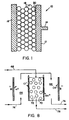
- the cathode compartment 10 includes a cathode plate member 12, a connection 14 to be connected to a source of DC voltage, an ion permeable membrane 16 and electrically conductive material 18.
- the electrically conductive material 18 provides a substantially increased effective cathode surface area as compared to the area of the surface 20 of cathode plate 12. As a result of the increased surface area, the local hydroxide concentration at the cathode surface is substantially reduced.
- Figures 2-6 provide representative process flow arrangements for balancing pH, ion concentration and liquid flow to minimize extreme process conditions and to limit the possibility of scale formation.
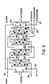
- a liquid flow path pattern is shown wherein concentrating electrolyte liquid 24 is passed in series through ion concentrating compartments 22 while liquid to be purified 26 is passed in series through ion depleting compartments 28.
- the ion depleting compartments 28 contain a mixture of anion and cation exchange resin beads.
- the ion concentrating compartments may also contain a mixture of anion and cation exchange resin.
- the ion concentrating compartments 22 and the ion depleting compartments 28 are bounded by anion permeable membranes, A, and cation permeable membranes, C.
- a third electrolyte liquid stream 30 is passed in series through anode compartments 32 and cathode compartment 34 containing electrically conductive material. Purified product 23 is recovered while concentrate 25 and electrode liquid 27 are sent to waste or recycled to their respective inlets.
- a liquid flow path pattern is shown wherein concentrating electrolyte liquid 40 is passed in series through anode compartment 32 and ion concentrating compartments 22 while liquid to be purified 26 is passed in series through ion depleting compartments 28.
- the ion concentrating compartments may also contain a mixture of anion and cation resin.
- the ion depleting compartments 28 contain a mixture of anion and cation exchange resin beads.
- the ion concentrating compartments 22 and the ion depleting compartments 28 are bounded by anion permeable membranes, A, and cation permeable membranes, C.
- a third electrolyte liquid stream 42 is passed through cathode compartment 34 containing electrically conductive material. Purified product 23 is recovered while concentrate 25 and electrode liquid 27 are sent to waste or recycled to their respective inlets.
- a liquid flow path pattern is shown wherein concentrating electrolyte liquid 44 is passed in series through anode compartment 32, ion concentrating compartments 22 and cathode compartment 34 containing electrically conductive material.
- Liquid to be purified 26 passes in series through ion depleting compartments 28.
- the ion depleting compartments 28 contain a mixture of anion and cation exchange resin heads.
- the ion concentrating compartments may also contain a mixture of anion and cation exchange resin.
- the concentrating compartments 22 and the ion depleting compartments 28 are bounded by anion permeable membranes, A, and cation permeable membranes C.
- Purified product 23 is recovered while concentrate and electrode liquid 43 is sent to waste or recycled to its inlet.
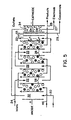
- concentrating electrolyte liquid 24 is passed in series through ion concentrating compartments 22 and neutral zone 33 while liquid to be purified 46 is passed in series through ion depleting compartments 28.
- the ion depleting compartments 28 contain a mixture of anion and cation exchange resin beads.
- the ion concentrating compartments may also contain a mixture of anion and cation exchange resin.
- the ion concentrating compartments 22 and the ion depleting compartments 28 are bounded by anion permeable membranes, A, and cation permeable membranes C.
- a third electrolyte liquid stream 30 is passed in series through the anode compartment 32 and cathode compartment 34 containing electrically conductive material. Purified product 23 is recovered while concentrate 29 and electrode liquid 27 are sent to waste or recycled to their respective inlets.
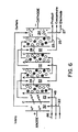
- concentrating electrolyte liquid 48 is passed in series through ion concentrating compartments 22 while liquid to be purified, 46, is passed in series through ion depleting compartments 28.
- the ion depleting compartments 28 contain a mixture of anion and cation exchange resin beads.
- the concentrating compartments may also contain a mixture of anion and cation exchange resin.
- the concentrating compartments 22 and the ion depleting compartments 28 are bounded by anion permeable membranes, A, and cation permeable membrane C.
- a third electrolyte liquid stream 30 is passed in series through anode compartments 32 and cathode compartment 34 containing electrically conductive materials. Purified product 23 is recovered while concentrate 25 and electrode liquid 27 are sent to waste or recycled to their respective inlets.
- the effect of the present invention on pH at the cathode is illustrated schematically.
- the conductive materials present in the cathode compartment are not shown.
- the cathode compartment 50 includes electrically conductive materials in contact with cathode plate 52.
- the ion depleting compartment 54 contains ion exchange resin beads 56 and is bounded by anion permeable membrane, A, and cation permeable membrane, C. Hydronium ions pass through membrane C so as to reduce pH at the membrane surface 58 in cathode compartment 50.
- hydroxide ion is produced at the cathode surface 58.
- the cathode compartment 64 and anode compartment 66 function as ion concentrating compartments.
- the aqueous liquid to be purified 68 passes through ion depleting compartment 70 including an anion permeable membrane A and a cation permeable membrane, C and including ion exchange resin beads 72.
- Aqueous liquid 74 for accepting ion species, e.g. Cl - and Na + is passes serially through anode compartment 66 and cathode compartment 64 containing electron conducting particles and is discarded as stream 76.
- Purified aqueous liquid 78 is recovered as product.
Abstract
Description
- The invention relates to an electrodeionization process and apparatus adapted to purify aqueous liquids to effect the production of high purity water and to minimize scale formation. The invention employs an electrodeionization module adapted to transfer ions in a liquid under the influence of a polar field.
- The purification of a liquid by reducing the concentration of ions or molecules in the liquid has been an area of substantial technological interest. Many techniques have been used to purify and isolate liquids or to obtain concentrated pools of specific ions or molecules from a liquid mixture. The most well-known processes include distillation, electrodialysis, reverse osmosis, liquid chromatography, membrane filtration and ion exchange. A lesser known method is electrodeionization, occasionally mistermed filled cell electrodialysis.
- The first apparatus and method for treating liquids by electrodeionization was described by Kollsman in U.S. Patent Nos. 2,689,826 and 2,815,320. The first of these patents describes an apparatus and,process for the removal of ions within a liquid mixture in a depleting chamber through a series of anionic and cationic membranes into a second volume of liquid in a concentrating chamber under the influence of an electrical potential which causes the preselected ions to travel in a predetermined direction. The volume of the liquid being treated is depleted of ions while the volume of the second liquid becomes enriched with the transferred ions and carries them in concentrated form. The second of these patents describes the use of macroporous beads formed of ion exchange resins as a filler material positioned between the anionic or cationic membranes. This ion exchange resin acts as a path for ion transfer and also serves as an increased conductivity bridge between the membranes for the movement of ions.
- The term "electrodeionization" refers to the process wherein an ion exchange material is positioned between anion and cationic membranes. The term "electrodialysis" refers to such a process which does not utilize ion exchange resins between the anionic and cationic membranes. Illustrative of other prior art attempts to use the combination of electrodialysis and ion exchange materials or resins to purify saline from brackish water are described in U.S. Pat. Nos. 2,794,770; 2,796,395; 2,947,688; 3,384,568; 2,923,674; 3,014,855 and 4,165,273. Attempts to improve electrodeionization apparatus are shown in U.S. Pat. Nos. 3,149,061; 3,291,713; 3,515,664; 3,562,139; 3,993,517 and 4,284,492.
- In any membrane separation process where ions become concentrated there is the potential to exceed solubility limits and form scale. In particular, calcium carbonate scale, CaCO3, is formed when the levels of Ca2+ and CO3 2- in water reach a solubility limit.
- Furthermore, the level of CO3 2- in water is function of the pH of the water and the equilibrium with bicarbonate, HCO3 -.
- By combining the equations above, the scale potential relative to calcium and bicarbonate concentrations and the pH of the water is defined.
- The potential for forming scale increases with an increase in calcium ion concentration, an increase in bicarbonate ion concentration or an increase in pH. In addition, the ion concentration increases when the electrodeionization module is operated to recover an increased percentage of incoming water as purified water.
- Reactions at the electrodeionization electrodes and water splitting in the electrodeionization process can create significant shifts in the pH of the waste water stream. The reactions occurring at the electrodes are shown below. The generation of OH- at the cathode creates an area of high scale potential.
Anode Reaction Cathode Reaction (4) 2H2O >> 4H+ + 4e- + O2 2Cl- >> 2e- + Cl2 (5) 2H2O +2e- >> 2OH- + H2 - Water splitting within the diluting compartments is an additional source of OH- within the electrodeionization module. In the concentrating compartment where OH- is entering through the anion membrane and especially along the surface of that anion membrane is were pH can become high resulting in areas with high risk of scale formation. Since pH is the negative log of the H+ concentration, what appears to be a small change in pH will have a significant impact to scale potential. For example an increase in one pH unit will increase the scale potential by a factor of 10.
- Formation of scale within the electrodeionization module will result in a very high electrical resistance and blocked flow channels leading to a quick decline in water quality produced. Several methods or combinations of methods presently are used to reduce the risk of scale in an electrodeionization module. In a first method water is pretreated before it enters an electrodeionization module to reduce the levels of Ca2+ and/or HCO3 - or to decrease pH thereby reducing the potential to form scale. For example, a properly functioning ion exchange softener will reduce Ca2+ levels by exchanging 2Na+ for the Ca2+ in the feed water. The solubility of Na2CO3 is very high with almost no risk of scale formation. The softener is regenerated by treating the resin with high concentrations of NaCI. Although a very effective method to reduce scale potential, softening has had limited success with the electrodeionization product. Improper maintenance, increases in feed water Ca2+ levels, and/or increases in the volume of water treated results in high leakage of Ca2+ and subsequent scaling of the electrodeionization module. In addition, the added cost and the size of a softener resin tank and salt regeneration tank are not desirable and especially does not fit with the concept of the compact, reliable and easy to use approach desired for a smaller laboratory water system.
- In a second pretreatment process, reverse osmosis (RO) is used to remove greater than 90 to 95% of the Ca2+ and HCO3 - in the feed water thereby significantly reducing the potential to form scale. However, in locations where the Ca2+ and HCO3 - levels are very high, (over 100 ppm of Ca2+ feeding the RO), enough Ca2+ and HCO3 - pass the RO so that an electrodeionization module can still suffer from scale formation. In these locations the current technology is forced to use softening to pretreat the RO prior to electrodeionization.
- A commercially successful electrodeionization apparatus and process is described in U.S. Pat No 4,632,745. The apparatus utilizes ion depleting compartments containing an ion exchange solid composition and a concentrating compartment which is free of ion exchange solid material. The electrodeionization apparatus includes two terminal electrode chambers containing an anode and a cathode respectively which are utilized to pass direct current transversely through the body of the apparatus containing a plurality of ion depleting compartments and ion concentrating compartments. In operation, the dissolved ionized salts of the liquid are transferred through the appropriate membrane from the ion depleting compartments to the ion concentrating compartments. The ions collected in the ion concentrating compartments are removed through discharge outlets and are directed to waste. The deposit of insoluble scale within the cathode compartment has been a problem associated with this process.
- It has been proposed in U.S. Pat; No. 3,341,441, in an electrodialysis process, to reverse periodically the direction of current flow in which case, the electrode once serving as the cathode becomes the anode while the anode chamber becomes the cathode. The solution flowing through the anode chamber becomes acidic due to anodic electrolytic action, and the acid thus formed tends to dissolve a small portion of scale formed therein during the time the electrode was cathodic. In the process the flow is reduced or stopped and thus the acid generated within the anode chamber is allowed to attain a sufficiently high concentration in the chamber so as to dissolve precipitated scale formed therein during the electrode's previous cathodic cycle and thereafter, reversing the polarity of the direct current is performed at periodic intervals. In a preferred form of the process, a third step is also employed comprising continuously flushing the cathode compartment with a sufficiently large volume of electrolyte solution to quickly remove any base generated therein. When the direct current is reversed, the ion depleting compartments become the ion concentrating compartments and the ion concentrating compartments become the ion depleting compartments. This process can be undesirable since a large volume of liquid being purified must be discharged to waste in a time interval immediately following voltage polarity reversal since the concentration of electrolyte in the newly formed ion depleting compartments is too high for a period of time to render the purity of the liquid product acceptable.
- It has also been proposed in U.S. Patent No. 4,956,071 to utilize voltage polarity reversal in an electrodeionization process in order to reduce scale formation. In the process, the voltage through the process is periodically reversed, typically every 15 to 20 minutes, with the voltage polarity in a given direction being approximately 50% of the time of process operation. With each voltage polarity reversal, the dilution compartments become concentration compartments and the concentration compartments become dilution compartments. As a result of the voltage polarity reversal, several valves are needed in the system for distributing the streams. Two valves typically are needed to direct the appropriate dilute stream to the final point of use. In addition, control means for these valves may be required to direct water to drain until acceptable purity levels are reached. In addition, one or two additional valves typically are used to control flow rates to electrode streams in order to optimize pH shifts and scale prevention. This patent discloses that an electrode spacer having an ion permeable membrane and positioned adjacent to anode and cathode optionally can be filled with ion exchange resin.
- Additional electrodeionization apparatus are disclosed by U.S. Patents 5,154,809; 5,308,466 and 5,316,637. U.S. Patent 5,308,466 discloses an electrodeionization apparatus utilizing concentration compartments containing ion exchange resin. The advantage provided by ion exchange resins in the concentrating compartments is improved performance and, specifically for improved removal or separation of highly charged, large highly hydrated, or weakly ionized species, silica, sulfate, calcium, heavy metals, and polar and ionized organics. The patent does not discuss the effect on scale formation as a result of utilizing resins in the concentrating compartments.
- U.S. Patent 4,226,688 discloses an electrodialysis apparatus including a cathode compartment and an anode compartment. A conductive slurry of carbon particles is continuously transferred between the electrode compartments at a rate of at least 1 ml/min/ per cm2 of electrode area. Hydrogen produced at the cathode compartment is absorbed by the carbon particles and released at the anode compartment. Scale production and corrosion problems are reduced by this process. The process is undesirably complex in that it requires pumping, conduits and control apparatus.
- Accordingly, it would be desirable to provide an electrodeionization process which minimizes or prevents scale formation. In addition, it would be desirable to provide such a process which does not require a complex piping, valving, pumping and control system for directing a newly produced dilute stream to a point of final use or to transfer scale reducing compositions between electrode components.
- The present invention is based upon the discovery that the inclusion of electrically conductive particles such as beads, granules or fibers in the cathode compartment significantly reduces scale formation when operating an electrodeionization device having anode and cathode compartments. The reduction in scaling in the cathode compartment results from the formation of lower local concentrations of hydroxide ion in the cathode compartment which is affected by electron transfer from the cathode to a large surface area of electrically conductive particles in the cathode compartment. The large surface area of electrically conductive particles reduces the local concentration of the formed hydroxide by increasing the surface area over which the hydroxide is concentrated. This ensures that high local hydroxide concentrations do not occur. The significantly reduced potential for scale formation is attained without the need for additional mechanical, control or storage apparatus.
- EP-A-0,503,589 discloses an electrodialysis apparatus which provides a process for the softening of hard water by the precipitation therefrom of an amount of calcium carbonate and separate withdrawal of precipitated calcium carbonate and soft water, characterised in that feed hard water is rendered alkaline by electrodialysis against a brine containing a water soluble alkali metal or calcium salt with periodical current reversal, using an apparatus comprising alternating product and brine compartments within a stack of asymmetric bipolar ion-exchange membranes so arranged that each brine compartment is bound by two cation-exchange layers and each product compartment is bound by two anion-exchange layers, which asymmetric bipolar ion-exchange membranes are of a kind which when the anion-exchange layer thereof faces a cathode the rate of delivery of anions into a compartment distal from the cathode exceeds the rate of delivery of cations in the opposite direction and when the anion-exchange layer faces the anode H+ and OH- ions are generated; and alkaline hard water is withdrawn from the stack and mixed with fresh hard water to produce an alkane diluate, which diluate is subjected to treatment by which calcium carbonate precipitation is induced; and mother liquor from such precipitation is recovered as product soft water.
- The present invention is as claimed in the claims.
- The preferred electron-conducting particles are carbon particles, metal particles or a mixture thereof.
- In apparatus according to this invention, one or other or each of the anode and cathode compartments can be connected to said means to feed water or other aqueous liquid, thereby in use to function as said at least one ion concentrating compartment.
- Preferred embodiments of the present invention will now be described with reference to the accompanying drawings, in which:
- Figure 1 is a partial cross-sectional view of the filled cathode compartment of this invention;
- Figure 2 is a schematic diagram of an electrodeionization process utilizing the apparatus of this invention;
- Figure 3 is a schematic diagram of an alternative electrodeionization process utilizing the apparatus of this invention;
- Figure 4 is a schematic diagram of an alternative electrodeionization process utilizing the apparatus of this invention;
- Figure 5 is a schematic diagram of an alternative electrodeionization process utilizing the apparatus of this invention ;
- Figure 6 is a schematic diagram of an alternative electrodeionization process utilizing the apparatus of this invention ;
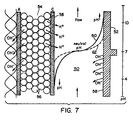
- Figure 7 illustrates the effect on pH in the cathode compartment as a result of this invention ; and
- Figure 8 is a schematic diagram of this invention wherein the concentrating compartments are only the anode compartment and the cathode compartment.
-
- In accordance with this invention, an electrodeionization apparatus and process are provided which utilize a cathode compartment filled with high surface area particles which conduct electrons such as carbon and/or metal beads, granules, or fibers or the like. The electrodeionization apparatus, can comprise one or a plurality of stages. Each stage comprises an anode compartment positioned at an end of a stack of depleting and concentrating compartments opposite from an end at which the filled cathode compartment is positioned. The anode and cathode includes an electrode spacer for passage of electrolyte and an ion permeable membrane. Only the spacer of the cathode compartment needs be filled with the electron conductive particles. However, if desired, the anode compartment also can be filled with the electron conductive particles. The remaining portion of each stage comprises a series of alternating depleting and concentration compartments. The depleting compartments contain ion exchange resin. The liquid to be depleted of ions can be passed in series, parallel or a combination of series and parallel through each depleting compartment in each stage while a second electrolyte liquid is passed through each concentrating compartment in each stage in order to effect transfer of ions from the first liquid in the depleting compartments to the second electrolyte liquid in the concentrating compartments. The concentrating compartments may also contain ion exchange resin. When a plurality of stages are utilized, the liquid removed from depleting compartments in an upstream stage can be directed in series into the depleting compartments of the next adjacent downstream stage. Similarly, the liquid removed from the concentrating compartments of an upstream stage can be directed in series to the concentrating compartments in the next adjacent downstream stage. These individual streams also can be split into multiple streams to feed a number of compartments in a parallel flow configuration. Electrolyte can be obtained from the feed product, neutral, or concentrate streams or from an independent source and passed through a spacer adjacent to each electrode in the electrodeionization apparatus and is removed from the electrodeionization apparatus. A neutral zone is a zone where little or no ion concentration or ion depletion occurs. Optionally, electrolyte from the spacer adjacent to the electrode can be passed through one or more neutral zones or to the concentrate stream prior to being directed to waste. In accordance with this invention, scale build up within the cathode is prevented by including therein materials which conduct electrons. Materials which conduct electrons provide improved control of or prevention of scale in the cathode as compared with particles which conduct ion species such as ion exchange resin particles. However, the materials utilized to conduct electrons also can contain a small amount, i.e. less than about 10 weight percent of particles which conduct ionic species, based upon the total weight of particles, without significantly reducing the effectiveness of the electron-conducting particles. The electrically conductive particles significantly increase the total effective surface area of the cathode. As a result, the electrode reaction and therefore the hydroxide ion produced is distributed over a significantly larger area so that the local hydroxide ion concentration and therefore the local pH is significantly reduced to a level wherein scale formation is minimized or prevented.
- The electron conducting particles comprising carbon and/or metal particles can be formed in any convenient configuration which provides a high surface area of the particles. Thus, the particles can be beads, granules, fibers or the like. In addition, the particles can be unsupported or supported on a matrix such a woven or nonwoven fibers such as polymeric fibers which are positioned within the liquid in the cathode compartment.
- Referring to Figure 1, a
cathode compartment 10 of this invention which is utilized with an electrodeionization apparatus is shown. Thecathode compartment 10 includes a cathode plate member 12, aconnection 14 to be connected to a source of DC voltage, an ionpermeable membrane 16 and electricallyconductive material 18. The electricallyconductive material 18 provides a substantially increased effective cathode surface area as compared to the area of thesurface 20 of cathode plate 12. As a result of the increased surface area, the local hydroxide concentration at the cathode surface is substantially reduced. - Figures 2-6 provide representative process flow arrangements for balancing pH, ion concentration and liquid flow to minimize extreme process conditions and to limit the possibility of scale formation.
- Referring to Figure 2, a liquid flow path pattern is shown wherein concentrating
electrolyte liquid 24 is passed in series throughion concentrating compartments 22 while liquid to be purified 26 is passed in series through ion depleting compartments 28. Theion depleting compartments 28 contain a mixture of anion and cation exchange resin beads. The ion concentrating compartments may also contain a mixture of anion and cation exchange resin. Theion concentrating compartments 22 and theion depleting compartments 28 are bounded by anion permeable membranes, A, and cation permeable membranes, C. A thirdelectrolyte liquid stream 30 is passed in series throughanode compartments 32 andcathode compartment 34 containing electrically conductive material.Purified product 23 is recovered whileconcentrate 25 andelectrode liquid 27 are sent to waste or recycled to their respective inlets. - Referrino to Figure 3, a liquid flow path pattern is shown wherein concentrating
electrolyte liquid 40 is passed in series throughanode compartment 32 andion concentrating compartments 22 while liquid to be purified 26 is passed in series through ion depleting compartments 28. The ion concentrating compartments may also contain a mixture of anion and cation resin. Theion depleting compartments 28 contain a mixture of anion and cation exchange resin beads. Theion concentrating compartments 22 and theion depleting compartments 28 are bounded by anion permeable membranes, A, and cation permeable membranes, C. A thirdelectrolyte liquid stream 42 is passed throughcathode compartment 34 containing electrically conductive material.Purified product 23 is recovered whileconcentrate 25 andelectrode liquid 27 are sent to waste or recycled to their respective inlets. - Referring to Figure 4, a liquid flow path pattern is shown wherein concentrating
electrolyte liquid 44 is passed in series throughanode compartment 32,ion concentrating compartments 22 andcathode compartment 34 containing electrically conductive material. Liquid to be purified 26 passes in series through ion depleting compartments 28. Theion depleting compartments 28 contain a mixture of anion and cation exchange resin heads. The ion concentrating compartments may also contain a mixture of anion and cation exchange resin. The concentrating compartments 22 and theion depleting compartments 28 are bounded by anion permeable membranes, A, and cation permeable membranesC. Purified product 23 is recovered while concentrate and electrode liquid 43 is sent to waste or recycled to its inlet. - Referring to Figure 5, a liquid flow path pattern is shown wherein concentrating
electrolyte liquid 24 is passed in series throughion concentrating compartments 22 andneutral zone 33 while liquid to be purified 46 is passed in series through ion depleting compartments 28. Theion depleting compartments 28 contain a mixture of anion and cation exchange resin beads. The ion concentrating compartments may also contain a mixture of anion and cation exchange resin. Theion concentrating compartments 22 and theion depleting compartments 28 are bounded by anion permeable membranes, A, and cation permeable membranes C. A thirdelectrolyte liquid stream 30 is passed in series through theanode compartment 32 andcathode compartment 34 containing electrically conductive material.Purified product 23 is recovered whileconcentrate 29 andelectrode liquid 27 are sent to waste or recycled to their respective inlets. - Referring to Figure 6, a liquid flow path pattern is shown wherein concentrating
electrolyte liquid 48 is passed in series throughion concentrating compartments 22 while liquid to be purified, 46, is passed in series through ion depleting compartments 28. Theion depleting compartments 28 contain a mixture of anion and cation exchange resin beads. The concentrating compartments may also contain a mixture of anion and cation exchange resin. The concentrating compartments 22 and theion depleting compartments 28 are bounded by anion permeable membranes, A, and cation permeable membrane C. A thirdelectrolyte liquid stream 30 is passed in series throughanode compartments 32 andcathode compartment 34 containing electrically conductive materials.Purified product 23 is recovered whileconcentrate 25 andelectrode liquid 27 are sent to waste or recycled to their respective inlets. - Referring to Figure 7, the effect of the present invention on pH at the cathode is illustrated schematically. For purposes of clarity in Figure 7, the conductive materials present in the cathode compartment are not shown. In fact, the
cathode compartment 50 includes electrically conductive materials in contact withcathode plate 52. Theion depleting compartment 54 contains ionexchange resin beads 56 and is bounded by anion permeable membrane, A, and cation permeable membrane, C. Hydronium ions pass through membrane C so as to reduce pH at themembrane surface 58 incathode compartment 50. During the purification process hydroxide ion is produced at thecathode surface 58. When conductive material is not present all the hydroxide ion is produced at thecathode surface 58 resulting in high local pH illustrated by thesolid line 60. With the presence of electrically conductive material, not shown, in thecathode compartment 50 the hydroxide ion is produced over the high surface area of the conductive material resulting in the lower local pH at thecathode surface 58 illustrated by the dottedline 62. The effect of the lower conductive material, not shown, in thecathode compartment 50 is to change the local surface pH from the values illustrated by thesolid line 60 to the values illustrated by the dottedline 62. - Referring to Figure 8, the
cathode compartment 64 andanode compartment 66 function as ion concentrating compartments. The aqueous liquid to be purified 68 passes throughion depleting compartment 70 including an anion permeable membrane A and a cation permeable membrane, C and including ionexchange resin beads 72.Aqueous liquid 74 for accepting ion species, e.g. Cl- and Na+ is passes serially throughanode compartment 66 andcathode compartment 64 containing electron conducting particles and is discarded asstream 76. Purifiedaqueous liquid 78 is recovered as product.
Claims (7)
- A process for purifying an impure aqueous liquid to remove ionic species in an electrodeionization apparatus by passing said impure aqueous liquid through an ion depleting compartment bounded by an anion permeable membrane (A) and a cation permeable membrane (C) and containing ion exchange resin beads (72) and passing water or other aqueous liquid for accepting said ionic species through an anode compartment (66) including an anion permeable membrane (A) and passing water or other aqueous liquid for accepting said ionic species through a cathode compartment (34,50,64) including a cation permeable membrane (16,58) said cathode compartment containing particles (18) capable of conducting electrons while producing an electrical potential between said cathode compartment (64) and said anode compartment (66) and passing electrical current through said ion depleting compartment (70).
- The process of claim 1, wherein said particles (18) capable of conducting electrons comprise metal particles, carbon particles, or a mixture containing metal and carbon particles.
- The process for purifying an impure aqueous liquid as claimed in either of claims 1 or 2 and including passing water or other aqueous liquid for accepting said ionic species through at least one ion concentrating compartment (22) bounded by an anion permeable membrane (A) and a cation permeable membrane (C).
- The process of claim 3, wherein said electrodeionization apparatus includes a plurality of ion depleting compartments (28) and a plurality of ion concentrating compartments (22).
- An electrodeionization apparatus for use in practising the method of any of claims 1 to 4, comprising an anode compartment (32;66), at least one ion depleting compartment (28;70) bounded by an anion permeable membrane (a) and a cation permeable membrane (C) and containing ion exchange resin beads (72), at least one ion concentrating compartment (22), an anode compartment (66) and a cathode compartment (34; 50; 64) the cathode compartment (34; 50; 64) containing particles (18) capable of conducting electrons, the apparatus including means to feed an impure aqueous liquid (26,46,68) to be purified to said at least one ion depleting compartment (28;70) and means to feed water or other aqueous liquid (30,42,44 or 74) through said cathode compartment.
- Apparatus according to claim 5, wherein the electron-conducting particles (18) are carbon particles, metal particles or a mixture thereof.
- Apparatus according to claim 5 or claim 6, wherein one or other or each of the anode and cathode compartment (64,66) is connected to said means to feed water or other aqueous liquid (74), and thereby in use to function as said at least one ion concentrating compartment.
Applications Claiming Priority (2)
| Application Number | Priority Date | Filing Date | Title |
|---|---|---|---|
| US08/638,040 US5593563A (en) | 1996-04-26 | 1996-04-26 | Electrodeionization process for purifying a liquid |
| US638040 | 1996-04-26 |
Publications (3)
| Publication Number | Publication Date |
|---|---|
| EP0803474A2 EP0803474A2 (en) | 1997-10-29 |
| EP0803474A3 EP0803474A3 (en) | 1998-07-08 |
| EP0803474B1 true EP0803474B1 (en) | 2003-04-02 |
Family
ID=24558395
Family Applications (1)
| Application Number | Title | Priority Date | Filing Date |
|---|---|---|---|
| EP97300606A Expired - Lifetime EP0803474B1 (en) | 1996-04-26 | 1997-01-30 | Electrodeionization apparatus and process for purifying a liquid |
Country Status (5)
| Country | Link |
|---|---|
| US (1) | US5593563A (en) |
| EP (1) | EP0803474B1 (en) |
| JP (1) | JP3416455B2 (en) |
| AT (1) | ATE236090T1 (en) |
| DE (1) | DE69720310T2 (en) |
Cited By (7)
| Publication number | Priority date | Publication date | Assignee | Title |
|---|---|---|---|---|
| US7744760B2 (en) | 2006-09-20 | 2010-06-29 | Siemens Water Technologies Corp. | Method and apparatus for desalination |
| US8045849B2 (en) | 2005-06-01 | 2011-10-25 | Siemens Industry, Inc. | Water treatment system and process |
| CN1902134B (en) * | 2003-11-13 | 2013-11-20 | 西门子工业公司 | Water treatment system and method |
| US9592472B2 (en) | 2006-06-13 | 2017-03-14 | Evoqua Water Technologies Llc | Method and system for irrigation |
| US10252923B2 (en) | 2006-06-13 | 2019-04-09 | Evoqua Water Technologies Llc | Method and system for water treatment |
| US10625211B2 (en) | 2006-06-13 | 2020-04-21 | Evoqua Water Technologies Llc | Method and system for water treatment |
| US11820689B2 (en) | 2017-08-21 | 2023-11-21 | Evoqua Water Technologies Llc | Treatment of saline water for agricultural and potable use |
Families Citing this family (60)
| Publication number | Priority date | Publication date | Assignee | Title |
|---|---|---|---|---|
| US5868915A (en) * | 1996-09-23 | 1999-02-09 | United States Filter Corporation | Electrodeionization apparatus and method |
| US5744028A (en) * | 1996-11-21 | 1998-04-28 | Konica Corporation | Water treating apparatus |
| EP1024885B1 (en) * | 1997-10-09 | 2002-12-18 | Millipore Corporation | Methods for producing solid subassemblies of fluidic particulate ion exchange material |
| US6017433A (en) * | 1997-11-12 | 2000-01-25 | Archer Daniels Midland Company | Desalting aqueous streams via filled cell electrodialysis |
| US6056878A (en) * | 1998-08-03 | 2000-05-02 | E-Cell Corporation | Method and apparatus for reducing scaling in electrodeionization systems and for improving efficiency thereof |
| US6284124B1 (en) | 1999-01-29 | 2001-09-04 | United States Filter Corporation | Electrodeionization apparatus and method |
| KR100339868B1 (en) * | 1999-02-10 | 2002-06-07 | 김용래 | A method for treating waste water using electrode reactor charged with particle electrode and device there of |
| US6296751B1 (en) | 1999-09-13 | 2001-10-02 | Leon Mir | Electrodeionization apparatus with scaling control |
| US6187162B1 (en) | 1999-09-13 | 2001-02-13 | Leon Mir | Electrodeionization apparatus with scaling control |
| US6241867B1 (en) | 1999-09-13 | 2001-06-05 | Leon Mir | Electrodeionization apparatus and packing therefor |
| US6254753B1 (en) | 1999-09-13 | 2001-07-03 | Leon Mir | High purity electrodeionization |
| US6241866B1 (en) | 1999-09-13 | 2001-06-05 | Leon Mir | Electrodeionization apparatus with fixed ion exchange materials |
| US6284117B1 (en) | 1999-12-22 | 2001-09-04 | Nanogen, Inc. | Apparatus and method for removing small molecules and ions from low volume biological samples |
| JP4481418B2 (en) * | 2000-03-23 | 2010-06-16 | オルガノ株式会社 | Electric deionized water production equipment |
| DE60143351D1 (en) | 2000-05-10 | 2010-12-09 | Millipore Corp | IMPROVED ELECTRIC INSULATION MODULE |
| GB0016846D0 (en) * | 2000-07-10 | 2000-08-30 | United States Filter Corp | Electrodeionisation Apparatus |
| US7147785B2 (en) * | 2000-09-28 | 2006-12-12 | Usfilter Corporation | Electrodeionization device and methods of use |
| JP3794268B2 (en) * | 2001-01-05 | 2006-07-05 | 栗田工業株式会社 | Electrodeionization apparatus and operation method thereof |
| US6607647B2 (en) | 2001-04-25 | 2003-08-19 | United States Filter Corporation | Electrodeionization apparatus with expanded conductive mesh electrode and method |
| US6649037B2 (en) | 2001-05-29 | 2003-11-18 | United States Filter Corporation | Electrodeionization apparatus and method |
| DE10147842B4 (en) * | 2001-09-27 | 2004-09-09 | Forschungszentrum Karlsruhe Gmbh | Device for magnetically ordered electrode ionization |
| AU2002337876A1 (en) | 2001-10-15 | 2003-04-28 | United States Filter Corporation | Apparatus for fluid purification and methods of manufacture and use thereof |
| DE60202512T2 (en) * | 2001-10-31 | 2005-12-22 | Kurita Water Industries, Ltd. | Device for electrodeionization |
| US7094325B2 (en) * | 2002-02-02 | 2006-08-22 | Ionics, Incorporated | EDI and related stacks and method and apparatus for preparing such |
| JP3864891B2 (en) | 2002-07-01 | 2007-01-10 | 栗田工業株式会社 | Electric deionizer |
| JP3794354B2 (en) * | 2002-07-08 | 2006-07-05 | 栗田工業株式会社 | Electrodeionization equipment |
| US7501061B2 (en) * | 2002-10-23 | 2009-03-10 | Siemens Water Technologies Holding Corp. | Production of water for injection using reverse osmosis |
| US7763157B2 (en) * | 2003-04-11 | 2010-07-27 | Millipore Corporation | Electrodeionization device |
| US7083733B2 (en) * | 2003-11-13 | 2006-08-01 | Usfilter Corporation | Water treatment system and method |
| US7862700B2 (en) * | 2003-11-13 | 2011-01-04 | Siemens Water Technologies Holding Corp. | Water treatment system and method |
| US7563351B2 (en) * | 2003-11-13 | 2009-07-21 | Siemens Water Technologies Holding Corp. | Water treatment system and method |
| JP5126772B2 (en) * | 2003-11-13 | 2013-01-23 | シーメンス インダストリー インコーポレイテッド | Water treatment system and method |
| US20050103717A1 (en) * | 2003-11-13 | 2005-05-19 | United States Filter Corporation | Water treatment system and method |
| US8377279B2 (en) | 2003-11-13 | 2013-02-19 | Siemens Industry, Inc. | Water treatment system and method |
| US7846340B2 (en) * | 2003-11-13 | 2010-12-07 | Siemens Water Technologies Corp. | Water treatment system and method |
| US7604725B2 (en) * | 2003-11-13 | 2009-10-20 | Siemens Water Technologies Holding Corp. | Water treatment system and method |
| GB0406141D0 (en) * | 2004-03-18 | 2004-04-21 | Boc Group Plc | Electromembrane process and apparatus |
| US7329358B2 (en) * | 2004-05-27 | 2008-02-12 | Siemens Water Technologies Holding Corp. | Water treatment process |
| US7452920B2 (en) * | 2004-09-17 | 2008-11-18 | Uchicago Argonne, Llc | Electronically and ionically conductive porous material and method for manufacture of resin wafers therefrom |
| US7658828B2 (en) * | 2005-04-13 | 2010-02-09 | Siemens Water Technologies Holding Corp. | Regeneration of adsorption media within electrical purification apparatuses |
| US20060231406A1 (en) * | 2005-04-13 | 2006-10-19 | Usfilter Corporation | Regeneration of adsorption media within electrical purification apparatuses |
| KR20080037050A (en) * | 2005-08-26 | 2008-04-29 | 엔테그리스, 아이엔씨. | Porous membranes containing exchange resin |
| US8114259B2 (en) * | 2006-06-13 | 2012-02-14 | Siemens Industry, Inc. | Method and system for providing potable water |
| US20080067069A1 (en) | 2006-06-22 | 2008-03-20 | Siemens Water Technologies Corp. | Low scale potential water treatment |
| US7820024B2 (en) * | 2006-06-23 | 2010-10-26 | Siemens Water Technologies Corp. | Electrically-driven separation apparatus |
| WO2008048656A2 (en) * | 2006-10-18 | 2008-04-24 | Kinetico Incorporated | Electroregeneration apparatus and water treatment method |
| KR101227853B1 (en) * | 2007-05-21 | 2013-01-31 | 삼성전자주식회사 | Water softening apparatus |
| BRPI0819884A2 (en) | 2007-11-30 | 2016-05-10 | Siemens Water Tech Corp | saltwater treatment method, water treatment system and electrically driven separation device |
| CN101468832A (en) * | 2007-12-25 | 2009-07-01 | 通用电气公司 | Electrolytic apparatus, method and washing facility including the electrolytic apparatus |
| JP2009220060A (en) * | 2008-03-18 | 2009-10-01 | Japan Organo Co Ltd | Electrically deionized water production apparatus and its deionization unit |
| JP4960288B2 (en) * | 2008-03-24 | 2012-06-27 | オルガノ株式会社 | Electric deionized water production apparatus and deionized water production method |
| CN102046253A (en) * | 2008-04-03 | 2011-05-04 | 西门子水处理技术公司 | Low energy system and method of desalinating seawater |
| KR20110000160A (en) * | 2009-06-26 | 2011-01-03 | 삼성전자주식회사 | Electrolysis apparatus and device with the apparatus |
| US8695343B2 (en) * | 2009-12-04 | 2014-04-15 | General Electric Company | Economical and sustainable disposal of zero liquid discharge salt byproduct |
| US8524062B2 (en) * | 2010-12-29 | 2013-09-03 | General Electric Company | Electrodeionization device and method with improved scaling resistance |
| JP5806038B2 (en) * | 2011-08-12 | 2015-11-10 | オルガノ株式会社 | Electric deionized water production equipment |
| US9339765B2 (en) | 2011-09-16 | 2016-05-17 | General Electric Company | Electrodialysis method and apparatus for passivating scaling species |
| JP2014087749A (en) * | 2012-10-30 | 2014-05-15 | Mitsui Eng & Shipbuild Co Ltd | Conductive filler for liquid junction ion transfer device and liquid junction ion transfer device |
| DE102013105177A1 (en) | 2013-05-21 | 2014-11-27 | Fraunhofer-Gesellschaft zur Förderung der angewandten Forschung e.V. | Process for obtaining metallic fractions and metal-depleted material from metal-containing materials |
| CN104250035B (en) * | 2014-09-18 | 2018-05-08 | 清华大学 | Electric drive departs from sub-device and the method using device processing water |
Family Cites Families (23)
| Publication number | Priority date | Publication date | Assignee | Title |
|---|---|---|---|---|
| NL96481C (en) | 1950-07-21 | |||
| US2794770A (en) | 1953-05-18 | 1957-06-04 | California Research Corp | Stabilization of cracked distillate fuel oils |
| US2796395A (en) | 1953-06-05 | 1957-06-18 | Dorr Oliver Inc | Electrolytic desalting of saline solutions |
| US2815320A (en) | 1953-10-23 | 1957-12-03 | Kollsman Paul | Method of and apparatus for treating ionic fluids by dialysis |
| US2947688A (en) | 1957-01-10 | 1960-08-02 | George W Murphy | Process and apparatus for the demineralization of saline water |
| GB879181A (en) | 1958-02-03 | 1961-10-04 | Permutit Co Ltd | Improvements relating to the removal of dissolved solids from liquids |
| GB882601A (en) | 1958-05-07 | 1961-11-15 | Permutit Co Ltd | Improvements relating to the treatment of aqueous liquids by electro-dialysis |
| NL288721A (en) | 1962-02-19 | |||
| GB1051659A (en) | 1962-11-22 | |||
| US3341441A (en) | 1964-01-07 | 1967-09-12 | Ionics | Method for preventing scale buildup during electrodialysis operation |
| US3291713A (en) | 1964-05-27 | 1966-12-13 | Ionics | Removal of weakly basic substances from solution by electrodeionization |
| US3515664A (en) | 1967-01-17 | 1970-06-02 | Allan M Johnson | Demineralizing process and apparatus |
| US3562139A (en) | 1968-08-05 | 1971-02-09 | Ionics | Cationic-anionic ion-exchange membrane |
| US3755135A (en) * | 1971-01-20 | 1973-08-28 | A Johnson | Electric demineralizing apparatus |
| US3993517A (en) | 1975-10-31 | 1976-11-23 | The United States Of America As Represented By The Secretary Of The Interior | Thin cell electromembrane separator |
| IL52758A0 (en) | 1977-08-16 | 1977-10-31 | Yeda Res & Dev | Improved device for electrodialysis |
| US4165273A (en) | 1977-12-20 | 1979-08-21 | Azarov Nikolai N | Device for producing deeply desalted water |
| US4284492A (en) | 1979-12-05 | 1981-08-18 | Karn William S | Reverse osmosis electrodialysis combined means |
| US4956071A (en) | 1984-07-09 | 1990-09-11 | Millipore Corporation | Electrodeionization apparatus and module |
| US5154809A (en) | 1984-07-09 | 1992-10-13 | Millipore Corporation | Process for purifying water |
| DE3568946D1 (en) | 1984-07-09 | 1989-04-27 | Millipore Corp | Improved electrodeionization apparatus and method |
| JP3009221B2 (en) | 1990-12-17 | 2000-02-14 | ユー・エス・フィルター/アイオンピュア・インコーポレーテッド | Electrodeionization equipment |
| IL97543A (en) * | 1991-03-14 | 1994-11-11 | Yeda Res & Dev | Electrodialysis reversal process and apparatus with bipolar membranes for hard-water softening |
-
1996
- 1996-04-26 US US08/638,040 patent/US5593563A/en not_active Expired - Lifetime
-
1997
- 1997-01-30 EP EP97300606A patent/EP0803474B1/en not_active Expired - Lifetime
- 1997-01-30 AT AT97300606T patent/ATE236090T1/en not_active IP Right Cessation
- 1997-01-30 DE DE69720310T patent/DE69720310T2/en not_active Expired - Lifetime
- 1997-04-24 JP JP12008297A patent/JP3416455B2/en not_active Expired - Lifetime
Cited By (8)
| Publication number | Priority date | Publication date | Assignee | Title |
|---|---|---|---|---|
| CN1902134B (en) * | 2003-11-13 | 2013-11-20 | 西门子工业公司 | Water treatment system and method |
| US8045849B2 (en) | 2005-06-01 | 2011-10-25 | Siemens Industry, Inc. | Water treatment system and process |
| US9592472B2 (en) | 2006-06-13 | 2017-03-14 | Evoqua Water Technologies Llc | Method and system for irrigation |
| US10252923B2 (en) | 2006-06-13 | 2019-04-09 | Evoqua Water Technologies Llc | Method and system for water treatment |
| US10625211B2 (en) | 2006-06-13 | 2020-04-21 | Evoqua Water Technologies Llc | Method and system for water treatment |
| US7744760B2 (en) | 2006-09-20 | 2010-06-29 | Siemens Water Technologies Corp. | Method and apparatus for desalination |
| US8182693B2 (en) | 2006-09-20 | 2012-05-22 | Siemens Industry, Inc. | Method and apparatus for desalination |
| US11820689B2 (en) | 2017-08-21 | 2023-11-21 | Evoqua Water Technologies Llc | Treatment of saline water for agricultural and potable use |
Also Published As
| Publication number | Publication date |
|---|---|
| EP0803474A2 (en) | 1997-10-29 |
| US5593563A (en) | 1997-01-14 |
| EP0803474A3 (en) | 1998-07-08 |
| DE69720310T2 (en) | 2004-02-12 |
| ATE236090T1 (en) | 2003-04-15 |
| DE69720310D1 (en) | 2003-05-08 |
| JP3416455B2 (en) | 2003-06-16 |
| JPH1043554A (en) | 1998-02-17 |
Similar Documents
| Publication | Publication Date | Title |
|---|---|---|
| EP0803474B1 (en) | Electrodeionization apparatus and process for purifying a liquid | |
| EP1133449B1 (en) | Method for preventing scaling in electrodeionization units | |
| US4956071A (en) | Electrodeionization apparatus and module | |
| US6896814B2 (en) | Fractional deionization process | |
| US5154809A (en) | Process for purifying water | |
| US4969983A (en) | Apparatus and process for the removal of acidic and basic gases from fluid mixtures using bipolar membranes | |
| USRE35741E (en) | Process for purifying water | |
| JP3244689B2 (en) | Electrodeionization and UV treatment method for purifying water | |
| US6056878A (en) | Method and apparatus for reducing scaling in electrodeionization systems and for improving efficiency thereof | |
| JP2002527238A5 (en) | ||
| US5376250A (en) | Method of producing water having a reduced salt content | |
| US20230182078A1 (en) | Electrodialysis process and bipolar membrane electrodialysis devices for silica removal | |
| WO2009051612A1 (en) | Electroregeneration apparatus and water treatment method | |
| JP2001198577A (en) | Electric deionizing device | |
| JP2002143854A (en) | Electrochemical water treating device | |
| JP3788318B2 (en) | Electrodeionization apparatus and electrodeionization method | |
| JPH08108184A (en) | Water treatment apparatus | |
| JP4531213B2 (en) | Desalination equipment | |
| JPH09294988A (en) | Pure water preparation device | |
| JP4250796B2 (en) | Electrodeionization equipment | |
| JP2000296314A (en) | Method and device for electrical desalting | |
| RU2001111863A (en) | Method and device for preventing scale formation in electrodeionization blocks |
Legal Events
| Date | Code | Title | Description |
|---|---|---|---|
| PUAI | Public reference made under article 153(3) epc to a published international application that has entered the european phase |
Free format text: ORIGINAL CODE: 0009012 |
|
| AK | Designated contracting states |
Kind code of ref document: A2 Designated state(s): AT BE CH DE DK ES FI FR GB GR IE IT LI LU MC NL PT SE |
|
| AX | Request for extension of the european patent |
Free format text: AL PAYMENT 970211;LT PAYMENT 970211;LV PAYMENT 970211;SI PAYMENT 970211 |
|
| PUAL | Search report despatched |
Free format text: ORIGINAL CODE: 0009013 |
|
| AK | Designated contracting states |
Kind code of ref document: A3 Designated state(s): AT BE CH DE DK ES FI FR GB GR IE IT LI LU MC NL PT SE |
|
| AX | Request for extension of the european patent |
Free format text: AL PAYMENT 970211;LT PAYMENT 970211;LV PAYMENT 970211;SI PAYMENT 970211 |
|
| 17P | Request for examination filed |
Effective date: 19981221 |
|
| 17Q | First examination report despatched |
Effective date: 19991229 |
|
| GRAG | Despatch of communication of intention to grant |
Free format text: ORIGINAL CODE: EPIDOS AGRA |
|
| GRAG | Despatch of communication of intention to grant |
Free format text: ORIGINAL CODE: EPIDOS AGRA |
|
| GRAH | Despatch of communication of intention to grant a patent |
Free format text: ORIGINAL CODE: EPIDOS IGRA |
|
| GRAH | Despatch of communication of intention to grant a patent |
Free format text: ORIGINAL CODE: EPIDOS IGRA |
|
| GRAA | (expected) grant |
Free format text: ORIGINAL CODE: 0009210 |
|
| AK | Designated contracting states |
Designated state(s): AT BE CH DE DK ES FI FR GB GR IE IT LI LU MC NL PT SE |
|
| AX | Request for extension of the european patent |
Extension state: AL LT LV SI |
|
| PG25 | Lapsed in a contracting state [announced via postgrant information from national office to epo] |
Ref country code: NL Free format text: LAPSE BECAUSE OF FAILURE TO SUBMIT A TRANSLATION OF THE DESCRIPTION OR TO PAY THE FEE WITHIN THE PRESCRIBED TIME-LIMIT Effective date: 20030402 Ref country code: LI Free format text: LAPSE BECAUSE OF FAILURE TO SUBMIT A TRANSLATION OF THE DESCRIPTION OR TO PAY THE FEE WITHIN THE PRESCRIBED TIME-LIMIT Effective date: 20030402 Ref country code: FI Free format text: LAPSE BECAUSE OF FAILURE TO SUBMIT A TRANSLATION OF THE DESCRIPTION OR TO PAY THE FEE WITHIN THE PRESCRIBED TIME-LIMIT Effective date: 20030402 Ref country code: CH Free format text: LAPSE BECAUSE OF FAILURE TO SUBMIT A TRANSLATION OF THE DESCRIPTION OR TO PAY THE FEE WITHIN THE PRESCRIBED TIME-LIMIT Effective date: 20030402 Ref country code: BE Free format text: LAPSE BECAUSE OF FAILURE TO SUBMIT A TRANSLATION OF THE DESCRIPTION OR TO PAY THE FEE WITHIN THE PRESCRIBED TIME-LIMIT Effective date: 20030402 Ref country code: AT Free format text: LAPSE BECAUSE OF FAILURE TO SUBMIT A TRANSLATION OF THE DESCRIPTION OR TO PAY THE FEE WITHIN THE PRESCRIBED TIME-LIMIT Effective date: 20030402 |
|
| REG | Reference to a national code |
Ref country code: GB Ref legal event code: FG4D |
|
| REG | Reference to a national code |
Ref country code: CH Ref legal event code: EP |
|
| REG | Reference to a national code |
Ref country code: IE Ref legal event code: FG4D |
|
| REF | Corresponds to: |
Ref document number: 69720310 Country of ref document: DE Date of ref document: 20030508 Kind code of ref document: P |
|
| PG25 | Lapsed in a contracting state [announced via postgrant information from national office to epo] |
Ref country code: SE Free format text: LAPSE BECAUSE OF FAILURE TO SUBMIT A TRANSLATION OF THE DESCRIPTION OR TO PAY THE FEE WITHIN THE PRESCRIBED TIME-LIMIT Effective date: 20030702 Ref country code: PT Free format text: LAPSE BECAUSE OF FAILURE TO SUBMIT A TRANSLATION OF THE DESCRIPTION OR TO PAY THE FEE WITHIN THE PRESCRIBED TIME-LIMIT Effective date: 20030702 Ref country code: GR Free format text: LAPSE BECAUSE OF FAILURE TO SUBMIT A TRANSLATION OF THE DESCRIPTION OR TO PAY THE FEE WITHIN THE PRESCRIBED TIME-LIMIT Effective date: 20030702 Ref country code: DK Free format text: LAPSE BECAUSE OF FAILURE TO SUBMIT A TRANSLATION OF THE DESCRIPTION OR TO PAY THE FEE WITHIN THE PRESCRIBED TIME-LIMIT Effective date: 20030702 |
|
| RAP2 | Party data changed (patent owner data changed or rights of a patent transferred) |
Owner name: MILLIPORE CORPORATION |
|
| NLT2 | Nl: modifications (of names), taken from the european patent patent bulletin |
Owner name: MILLIPORE CORPORATION |
|
| NLV1 | Nl: lapsed or annulled due to failure to fulfill the requirements of art. 29p and 29m of the patents act | ||
| LTIE | Lt: invalidation of european patent or patent extension |
Effective date: 20030402 |
|
| REG | Reference to a national code |
Ref country code: CH Ref legal event code: PL |
|
| PG25 | Lapsed in a contracting state [announced via postgrant information from national office to epo] |
Ref country code: ES Free format text: LAPSE BECAUSE OF FAILURE TO SUBMIT A TRANSLATION OF THE DESCRIPTION OR TO PAY THE FEE WITHIN THE PRESCRIBED TIME-LIMIT Effective date: 20031030 |
|
| ET | Fr: translation filed | ||
| PG25 | Lapsed in a contracting state [announced via postgrant information from national office to epo] |
Ref country code: LU Free format text: LAPSE BECAUSE OF NON-PAYMENT OF DUE FEES Effective date: 20040130 Ref country code: IE Free format text: LAPSE BECAUSE OF NON-PAYMENT OF DUE FEES Effective date: 20040130 |
|
| PG25 | Lapsed in a contracting state [announced via postgrant information from national office to epo] |
Ref country code: MC Free format text: LAPSE BECAUSE OF NON-PAYMENT OF DUE FEES Effective date: 20040131 |
|
| PLBE | No opposition filed within time limit |
Free format text: ORIGINAL CODE: 0009261 |
|
| STAA | Information on the status of an ep patent application or granted ep patent |
Free format text: STATUS: NO OPPOSITION FILED WITHIN TIME LIMIT |
|
| 26N | No opposition filed |
Effective date: 20040105 |
|
| REG | Reference to a national code |
Ref country code: IE Ref legal event code: MM4A |
|
| REG | Reference to a national code |
Ref country code: FR Ref legal event code: ST Effective date: 20091030 |
|
| PG25 | Lapsed in a contracting state [announced via postgrant information from national office to epo] |
Ref country code: FR Free format text: LAPSE BECAUSE OF NON-PAYMENT OF DUE FEES Effective date: 20090202 |
|
| REG | Reference to a national code |
Ref country code: FR Ref legal event code: D3 Effective date: 20120130 |
|
| REG | Reference to a national code |
Ref country code: FR Ref legal event code: CD Owner name: EMD MILLIPORE CORPORATION Effective date: 20120327 |
|
| PGRI | Patent reinstated in contracting state [announced from national office to epo] |
Ref country code: FR Effective date: 20120203 |
|
| REG | Reference to a national code |
Ref country code: DE Ref legal event code: R082 Ref document number: 69720310 Country of ref document: DE Representative=s name: LUDERSCHMIDT, SCHUELER & PARTNER GBR, DE |
|
| REG | Reference to a national code |
Ref country code: DE Ref legal event code: R082 Ref document number: 69720310 Country of ref document: DE Representative=s name: MAI DOERR BESIER PATENTANWAELTE, DE Effective date: 20120613 Ref country code: DE Ref legal event code: R082 Ref document number: 69720310 Country of ref document: DE Representative=s name: MAI DOERR BESIER PATENTANWAELTE, DE Effective date: 20120628 Ref country code: DE Ref legal event code: R081 Ref document number: 69720310 Country of ref document: DE Owner name: EMD MILLIPORE CORPORATION, US Free format text: FORMER OWNER: MILLIPORE CORP., BEDFORD, US Effective date: 20120613 Ref country code: DE Ref legal event code: R081 Ref document number: 69720310 Country of ref document: DE Owner name: EMD MILLIPORE CORPORATION, BILLERICA, US Free format text: FORMER OWNER: MILLIPORE CORP., BEDFORD, MASS., US Effective date: 20120613 |
|
| REG | Reference to a national code |
Ref country code: FR Ref legal event code: PLFP Year of fee payment: 20 |
|
| PGFP | Annual fee paid to national office [announced via postgrant information from national office to epo] |
Ref country code: FR Payment date: 20151208 Year of fee payment: 20 |
|
| PGFP | Annual fee paid to national office [announced via postgrant information from national office to epo] |
Ref country code: DE Payment date: 20160127 Year of fee payment: 20 Ref country code: IT Payment date: 20160127 Year of fee payment: 20 |
|
| PGFP | Annual fee paid to national office [announced via postgrant information from national office to epo] |
Ref country code: GB Payment date: 20160127 Year of fee payment: 20 |
|
| REG | Reference to a national code |
Ref country code: DE Ref legal event code: R071 Ref document number: 69720310 Country of ref document: DE |
|
| REG | Reference to a national code |
Ref country code: GB Ref legal event code: PE20 Expiry date: 20170129 |
|
| PG25 | Lapsed in a contracting state [announced via postgrant information from national office to epo] |
Ref country code: GB Free format text: LAPSE BECAUSE OF EXPIRATION OF PROTECTION Effective date: 20170129 |