EP0803675A2 - Tube connection in particular for connecting two tubular fuselage parts of a flying body - Google Patents
Tube connection in particular for connecting two tubular fuselage parts of a flying body Download PDFInfo
- Publication number
- EP0803675A2 EP0803675A2 EP97106217A EP97106217A EP0803675A2 EP 0803675 A2 EP0803675 A2 EP 0803675A2 EP 97106217 A EP97106217 A EP 97106217A EP 97106217 A EP97106217 A EP 97106217A EP 0803675 A2 EP0803675 A2 EP 0803675A2
- Authority
- EP
- European Patent Office
- Prior art keywords
- sections
- pipe
- pipe connection
- section
- connection according
- Prior art date
- Legal status (The legal status is an assumption and is not a legal conclusion. Google has not performed a legal analysis and makes no representation as to the accuracy of the status listed.)
- Granted
Links
Images

Classifications
-
- F—MECHANICAL ENGINEERING; LIGHTING; HEATING; WEAPONS; BLASTING
- F16—ENGINEERING ELEMENTS AND UNITS; GENERAL MEASURES FOR PRODUCING AND MAINTAINING EFFECTIVE FUNCTIONING OF MACHINES OR INSTALLATIONS; THERMAL INSULATION IN GENERAL
- F16L—PIPES; JOINTS OR FITTINGS FOR PIPES; SUPPORTS FOR PIPES, CABLES OR PROTECTIVE TUBING; MEANS FOR THERMAL INSULATION IN GENERAL
- F16L21/00—Joints with sleeve or socket
- F16L21/06—Joints with sleeve or socket with a divided sleeve or ring clamping around the pipe-ends
-
- F—MECHANICAL ENGINEERING; LIGHTING; HEATING; WEAPONS; BLASTING
- F16—ENGINEERING ELEMENTS AND UNITS; GENERAL MEASURES FOR PRODUCING AND MAINTAINING EFFECTIVE FUNCTIONING OF MACHINES OR INSTALLATIONS; THERMAL INSULATION IN GENERAL
- F16L—PIPES; JOINTS OR FITTINGS FOR PIPES; SUPPORTS FOR PIPES, CABLES OR PROTECTIVE TUBING; MEANS FOR THERMAL INSULATION IN GENERAL
- F16L21/00—Joints with sleeve or socket
- F16L21/08—Joints with sleeve or socket with additional locking means
-
- F—MECHANICAL ENGINEERING; LIGHTING; HEATING; WEAPONS; BLASTING
- F16—ENGINEERING ELEMENTS AND UNITS; GENERAL MEASURES FOR PRODUCING AND MAINTAINING EFFECTIVE FUNCTIONING OF MACHINES OR INSTALLATIONS; THERMAL INSULATION IN GENERAL
- F16L—PIPES; JOINTS OR FITTINGS FOR PIPES; SUPPORTS FOR PIPES, CABLES OR PROTECTIVE TUBING; MEANS FOR THERMAL INSULATION IN GENERAL
- F16L23/00—Flanged joints
- F16L23/04—Flanged joints the flanges being connected by members tensioned in the radial plane
-
- Y—GENERAL TAGGING OF NEW TECHNOLOGICAL DEVELOPMENTS; GENERAL TAGGING OF CROSS-SECTIONAL TECHNOLOGIES SPANNING OVER SEVERAL SECTIONS OF THE IPC; TECHNICAL SUBJECTS COVERED BY FORMER USPC CROSS-REFERENCE ART COLLECTIONS [XRACs] AND DIGESTS
- Y10—TECHNICAL SUBJECTS COVERED BY FORMER USPC
- Y10S—TECHNICAL SUBJECTS COVERED BY FORMER USPC CROSS-REFERENCE ART COLLECTIONS [XRACs] AND DIGESTS
- Y10S285/00—Pipe joints or couplings
- Y10S285/913—Interdigitating
Definitions
- the invention relates to a pipe connection, in particular for connecting two tubular fuselage parts of a missile.
- the invention has for its object to provide a high-strength and highly rigid pipe connection.
- the pipe connection should be detachable.
- the pipe connection should allow easy assembly. Costs and manufacturing effort should be low.
- the construction volume should be small.
- the pipe connection should leave a large free cross section. Enlargements of the Outside diameter through the pipe connection should be avoided.
- the pipe connection should continue to be free of play.
- ring sections with threaded bores are preferably arranged within the circumferential sections thus joined, which are aligned with the radial bores of the circumferential sections.
- an "asymmetrical radial screw connection" is thus provided.
- Such an asymmetrical radial screw connection has the advantage that the two tube parts can be freely moved relative to one another in a small area perpendicular to the dividing line of the two peripheral sections. This means that there are no large radial internal stresses when screwing. The allows an excellent form fit.
- the asymmetrical radial screw connection is loaded with a bending moment, the force is mainly transmitted via the screws.
- Embodiments of the invention are the subject of the dependent claims.
- 10 denotes a first pipe part.
- the first pipe part 10 is to be connected to a second pipe part 12.
- the tubular parts 10 and 12 are tubular parts of the fuselage of a missile.
- the tube part 10 has, along the edge to be connected, on a first circumferential section 14, which extends over approximately 180 °, an outer diameter that is reduced compared to a second circumferential section 16.
- the outer diameter of the first peripheral section 14 corresponds minus an assembly tolerance of the inner diameter of the second circumferential section 16.
- the tube part 12 along the edge to be connected has a reduced outer diameter compared to a second circumferential section 20 on a first circumferential section 18 which extends over approximately 180 °.
- the outer diameter of the first circumferential section 18 minus a joining tolerance corresponds to the inner diameter of the second circumferential section 20.
- the edge parts of the two pipe parts 10 and 12 to be connected are designed to match.
- each tube part 10 or 12 has the peripheral section 14 or 18 with a smaller outside diameter inserted into a peripheral section 16 or 20 with a larger outside diameter of the other tube part 21 or 10, respectively.
- the peripheral sections 14, 16, 18 and 20 are provided with radial bores 22 and 24 for connecting screws.
- Ring sections 26 and 28 with threaded bores 30 are arranged within the circumferential sections 14, 20 and 18, 16 thus assembled.
- the threaded bores 30 are aligned with the radial bores 22 and 24 of the peripheral sections 14, 20 and 18, 16.
- the ring sections 26 and 28 each extend over 180 °.
- the ring section 26 lies in the area of the peripheral sections 14 and 20.
- the ring section 28 lies in the area of the peripheral sections 18 and 16.
- a longitudinal slot 32 or 34 is formed between the peripheral sections 14 and 16 or 18 and 20 of a tube part 10 or 12.
- the longitudinal slot 32 or 34 is one between the peripheral sections 18 and 20 or 14 and 16 the other tube part 12 or 10 formed step transition 36 or 38 can be inserted.
- a longitudinal slot 32 and 34 and diametrically opposite a step transition 36 and 38 are provided on each of the tube parts 10 and 12.
- the circumferential sections 16 and 20 with a larger outside diameter have, on the outside, following the radial bores 24, countersinks 40 for screw heads 42.
Abstract
Description
Die Erfindung betrifft eine Rohrverbindung, insbesondere zum Verbinden zweier rohrförmiger Rumpfteile eines Flugkörpers.The invention relates to a pipe connection, in particular for connecting two tubular fuselage parts of a missile.
Bei bekannten Rohrverbindungen werden Rohrteile, die in ihren zu verbindenden Randbereichen unterschiedliche Durchmesser aufweisen, ineinandergeschoben und durch radiale Schrauben miteinander verbunden. Dabei müssen, um einen Formschluß zu erzielen, durch das Festziehen der Schrauben das innere Rohrteil radial aufgeweitet oder das äußere Rohrteil zusammengedrückt werden. Diese Deformation verbraucht einen großen Teil der Schraubkraft. Der erreichbare Formschluß ist schlecht.In known pipe connections, pipe parts which have different diameters in their edge regions to be connected are pushed into one another and connected to one another by radial screws. To achieve a positive connection, the inner tube part must be radially expanded or the outer tube part compressed by tightening the screws. This deformation consumes a large part of the tightening force. The form fit that can be achieved is poor.
Die bekannte Art der Rohrverbindung ist insbesondere nicht zufriedenstellend beim Verbinden von rohrförmigen Rumpfteilen hochagiler Flugkörper. Bei diesen treten extreme Beanspruchungen der Rohrverbindungen auf.The known type of pipe connection is particularly unsatisfactory when connecting tubular fuselage parts of highly agile missiles. Extreme stresses on the pipe connections occur with these.
Der Erfindung liegt die Aufgabe zugrunde, eine hochfeste und hochsteife Rohrverbindung zu schaffen.The invention has for its object to provide a high-strength and highly rigid pipe connection.
Die Rohrverbindung soll lösbar sein. Die Rohrverbindung soll eine leichte Montage ermöglichen. Kosten und Fertigungsaufwand sollen gering sein. Das Bauvolumen soll gering sein. Weiterhin soll die Rohrverbindung einen großen freien Querschnitt freilassen. Vergrößerungen des Außendurchmessers durch die Rohrverbindung sollen vermieden werden. Die Rohrverbindung soll weiterhin spielfrei sein.The pipe connection should be detachable. The pipe connection should allow easy assembly. Costs and manufacturing effort should be low. The construction volume should be small. Furthermore, the pipe connection should leave a large free cross section. Enlargements of the Outside diameter through the pipe connection should be avoided. The pipe connection should continue to be free of play.
Erfindungsgemäß wird die gestellte Aufgabe dadurch gelöst, daß
- (a) jeder der Rohrteile längs des mit dem anderen Rohrteil zu verbindenden Randes auf einem ersten Umfangsabschnitt einen gegenüber einem zweiten Umfangsabschnitt verminderten Außendurchmesser aufweist, der abzüglich einer Zusammenfüge-Toleranz dem Innendurchmesser des zweiten Umfangsabschnitts entspricht,
- (b) die Rohrteile so zusammengefügt sind, daß von jedem Rohrteil der Umfangsabschnitt mit geringerem Außendurchmesser in einen Umfangsabschnitt mit größerem Außendurchmesser des jeweils anderen Rohrteils eingeschoben ist, und
- (c) die Umfangsabschnitte mit radialen Bohrungen für Verbindungsschrauben versehen sind.
- (a) each of the tube parts along the edge to be connected to the other tube part has a reduced outer diameter on a first circumferential section compared to a second circumferential section, which minus a joining tolerance corresponds to the inside diameter of the second circumferential section,
- (b) the pipe parts are joined together so that the circumferential section with a smaller outer diameter is inserted into a circumferential section with a larger outer diameter of the respective other pipe part of each pipe part, and
- (c) the peripheral sections are provided with radial bores for connecting screws.
Vorzugsweise sind dabei innerhalb der so zusammengefügten Umfangsabschnitte Ringabschnitte mit Gewindebohrungen angeordnet sind, die mit den radialen Bohrungen der Umfangsabschnitte fluchten.In this case, ring sections with threaded bores are preferably arranged within the circumferential sections thus joined, which are aligned with the radial bores of the circumferential sections.
Nach der Erfindung wird somit eine "asymmetrische Radialverschraubung" vorgesehen. Eine solche asymmetrische Radialverschraubung hat den Vorteil, daß die beiden Rohrteile senkrecht zur Trennlinie der beiden Umfangsabschnitte in einem kleinen Bereich frei zueinander verschoben werden können. Dadurch entstehen beim Verschrauben keine großen radialen Eigenspannungen. Das gestattet es, einen hervorragenden Formschluß herzustellen. Bei einer Belastung der asymmetrischen Radialverschraubung mit einem Biegemoment wird die Kraft hauptsächlich über die Schrauben übertragen.According to the invention, an "asymmetrical radial screw connection" is thus provided. Such an asymmetrical radial screw connection has the advantage that the two tube parts can be freely moved relative to one another in a small area perpendicular to the dividing line of the two peripheral sections. This means that there are no large radial internal stresses when screwing. The allows an excellent form fit. When the asymmetrical radial screw connection is loaded with a bending moment, the force is mainly transmitted via the screws.
Ausgestaltungen der Erfindung sind Gegenstand der Unteransprüche.Embodiments of the invention are the subject of the dependent claims.
Ein Ausführungsbeispiel der Erfindung ist nachstehend unter Bezugnahme auf die zugehörigen Zeichnungen näher erläutert.
- Fig.1
- ist eine perspektivische Darstellung zweier durch eine asymmetrische Radialverschraubung zu verbindender Rohrteile im auseinandergezogenen Zustand.
- Fig.2
- ist eine perspektivische Darstellung der beiden Rohrteile im verbundenen Zustand.
- Fig.3
- zeigt einen Längsschnitt eines Endabschnitts eines der Rohrteile von Fig.1 und 2.
- Fig.4
- zeigt einen Querschnitt des Endabschnitts von Fig.3.
- Fig. 1
- is a perspective view of two pipe parts to be connected by an asymmetrical radial screw connection in the extended state.
- Fig. 2
- is a perspective view of the two pipe parts in the connected state.
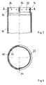
- Fig. 3
- shows a longitudinal section of an end portion of one of the tube parts of Figures 1 and 2.
- Fig. 4
- shows a cross section of the end portion of Figure 3.
In Fig.1 ist mit 10 ein erster Rohrteil bezeichnet. Der erste Rohrteil 10 soll mit einem zweiten Rohrteil 12 verbunden werden. Die Rohrteile 10 und 12 sind rohrförmige Teile des Rumpfes eines Flugkörpers.In Figure 1, 10 denotes a first pipe part. The
Der Rohrteil 10 weist längs des zu verbindenden Randes auf einem ersten, sich über etwa 180° erstreckenden Umfangsabschnitt 14 einen gegenüber einem Zweiten Umfangsabschnitt 16 verminderten Außendurchmesser auf. Der Außendurchmesser des ersten Umfangsabschnitts 14 entspricht abzüglich einer Zusammenfüge-Toleranz dem Innendurchmesser des zweiten Umfangsabschnitts 16. In entsprechender Weise weist der Rohrteil 12 längs des zu verbindenden Randes auf einem ersten, sich über etwa 180° erstreckenden Umfangsabschnitt 18 einen gegenüber einem zweiten Umfangsabschnitt 20 verminderten Außendurchmesser auf. Der Außendurchmesser des ersten Umfangsabschnitts 18 entspricht abzüglich einer Zusammenfüge-Toleranz dem Innendurchmesser des zweiten Umfangsabschnitts 20. Tatsächlich sind die zu verbindenden Randteile der beiden Rohrteile 10 und 12 übereinstimmend ausgebildet. Der Rohrteil 12 ist jedoch mit seinem Randteil gegenüber dem Rohrteil 10 um 180° um die Rohrachse verdreht. Die Rohrteile 10 und 12 sind dann so zusammengefügt, daß von jedem Rohrteil 10 oder 12 der Umfangsabschnitt 14 bzw. 18 mit geringerem Außendurchmesser in einen Umfangsabschnitt 16 bzw. 20 mit größerem Außendurchmesser des jeweils anderen Rohrteils 21 bzw. 10 eingeschoben ist. Die Umfangsabschnitte 14, 16, 18 und 20 sind mit radialen Bohrungen 22 bzw. 24 für Verbindungsschrauben versehen.The
Innerhalb der so zusammengefügten Umfangsabschnitte 14, 20 und 18, 16 sind Ringabschnitte 26 bzw. 28 mit Gewindebohrungen 30 angeordnet. Die Gewindebohrungen 30 fluchten mit den radialen Bohrungen 22 und 24 der Umfangsabschnitte 14, 20 bzw. 18, 16. Die Ringabschnitte 26 und 28 erstrecken sich jeweils über 180°. Dabei liegt der Ringabschnitt 26 im Bereich der Umfangsabschnitte 14 und 20. Der Ringabschnitt 28 liegt im Bereich der Umfangsabschnitte 18 und 16.
Zwischen den Umfangsabschnitten 14 und 16 bzw. 18 und 20 eines Rohrteils 10 bzw. 12 ist jeweils ein Längsschlitz 32 bzw. 34 gebildet. In den Längsschlitz 32 bzw. 34 ist ein zwischen den Umfangsabschnitten 18 und 20 bzw. 14 und 16 des anderen Rohrteils 12 bzw. 10 gebildeter Stufenübergang 36 bzw. 38 einschiebbar. Bei der dargestellten Ausführung ist an jedem der Rohrteile 10 und 12 ein Längsschlitz 32 bzw. 34 und diametral dazu gegenüberliegend ein Stufenübergang 36 bzw. 38 vorgesehen.A
Die Umfangsabschnitte 16 und 20 mit größerem Außendurchmesser weisen auf der Außenseite anschließend an die radialen Bohrungen 24 Senkungen 40 für Schraubenköpfe 42 auf.The
Claims (8)
Applications Claiming Priority (2)
| Application Number | Priority Date | Filing Date | Title |
|---|---|---|---|
| DE19615716 | 1996-04-22 | ||
| DE19615716A DE19615716A1 (en) | 1996-04-22 | 1996-04-22 | Pipe connection, in particular for connecting two tubular fuselage parts of a missile |
Publications (3)
| Publication Number | Publication Date |
|---|---|
| EP0803675A2 true EP0803675A2 (en) | 1997-10-29 |
| EP0803675A3 EP0803675A3 (en) | 1998-09-30 |
| EP0803675B1 EP0803675B1 (en) | 2000-09-20 |
Family
ID=7791892
Family Applications (1)
| Application Number | Title | Priority Date | Filing Date |
|---|---|---|---|
| EP97106217A Expired - Lifetime EP0803675B1 (en) | 1996-04-22 | 1997-04-16 | Tube connection in particular for connecting two tubular fuselage parts of a flying body |
Country Status (3)
| Country | Link |
|---|---|
| US (1) | US5876072A (en) |
| EP (1) | EP0803675B1 (en) |
| DE (2) | DE19615716A1 (en) |
Cited By (1)
| Publication number | Priority date | Publication date | Assignee | Title |
|---|---|---|---|---|
| WO2017166275A1 (en) * | 2016-04-01 | 2017-10-05 | 深圳市大疆创新科技有限公司 | Airframe connection components for unmanned aerial vehicle, and unmanned aerial vehicle |
Families Citing this family (10)
| Publication number | Priority date | Publication date | Assignee | Title |
|---|---|---|---|---|
| DE19735452C2 (en) * | 1997-08-16 | 1999-07-22 | Bodenseewerk Geraetetech | Pipe connection, in particular for connecting two tubular fuselage parts of a missile |
| US20040262922A1 (en) * | 2003-06-27 | 2004-12-30 | Lindab Ab | Assembly system for a pipe coupling |
| WO2005001323A1 (en) * | 2003-06-27 | 2005-01-06 | Lindab Ab | Assembly system for a pipe coupling |
| DE102006060360B8 (en) * | 2006-12-20 | 2010-09-30 | Airbus Deutschland Gmbh | Fuselage section to form a fuselage cell of an aircraft |
| DE102009021369A1 (en) * | 2009-05-12 | 2010-11-18 | Airbus Operations Gmbh | Method for producing an aircraft fuselage and fuselage |
| US8708601B2 (en) | 2010-02-16 | 2014-04-29 | Jensen Enterprises, Inc. | Box culvert |
| CN102765472B (en) * | 2012-07-31 | 2015-03-11 | 江西洪都航空工业集团有限责任公司 | Modular connection device for airplane body |
| DE102013102812B4 (en) * | 2013-03-19 | 2017-01-26 | Airbus Operations Gmbh | Hull structure for a means of transport, means of transport and method of making a hull structure for a means of transport |
| CN111332492B (en) * | 2020-03-06 | 2021-06-01 | 北京机电工程研究所 | Aircraft cabin section cable-free butt joint device and butt joint method thereof |
| USD977044S1 (en) | 2020-05-11 | 2023-01-31 | Gary Kemp | Inflatable zeotrope ball |
Citations (2)
| Publication number | Priority date | Publication date | Assignee | Title |
|---|---|---|---|---|
| US4348956A (en) * | 1980-08-29 | 1982-09-14 | The United States Of America As Represented By The Secretary Of The Army | Artillery shell comprising two sections having complementary coupling members for connecting the sections together |
| US5290974A (en) * | 1993-03-12 | 1994-03-01 | Arvin Industries, Inc. | Tab and notch locator for exhaust systems |
Family Cites Families (4)
| Publication number | Priority date | Publication date | Assignee | Title |
|---|---|---|---|---|
| US1639999A (en) * | 1926-02-06 | 1927-08-23 | Omar R Humphreys | Sewer pipe |
| US2710763A (en) * | 1951-02-24 | 1955-06-14 | Bendix Aviat Corp | Quick disconnect mounting |
| US2945704A (en) * | 1957-07-23 | 1960-07-19 | Hughes Aircraft Co | Nose section-quick disconnect |
| DE1911697C3 (en) * | 1969-03-03 | 1974-03-21 | 6600 Saarbruecken | Detachable connection for drill pipes used in bored pile manufacture |
-
1996
- 1996-04-22 DE DE19615716A patent/DE19615716A1/en not_active Withdrawn
-
1997
- 1997-04-16 DE DE59702368T patent/DE59702368D1/en not_active Expired - Fee Related
- 1997-04-16 EP EP97106217A patent/EP0803675B1/en not_active Expired - Lifetime
- 1997-04-21 US US08/845,028 patent/US5876072A/en not_active Expired - Fee Related
Patent Citations (2)
| Publication number | Priority date | Publication date | Assignee | Title |
|---|---|---|---|---|
| US4348956A (en) * | 1980-08-29 | 1982-09-14 | The United States Of America As Represented By The Secretary Of The Army | Artillery shell comprising two sections having complementary coupling members for connecting the sections together |
| US5290974A (en) * | 1993-03-12 | 1994-03-01 | Arvin Industries, Inc. | Tab and notch locator for exhaust systems |
Cited By (1)
| Publication number | Priority date | Publication date | Assignee | Title |
|---|---|---|---|---|
| WO2017166275A1 (en) * | 2016-04-01 | 2017-10-05 | 深圳市大疆创新科技有限公司 | Airframe connection components for unmanned aerial vehicle, and unmanned aerial vehicle |
Also Published As
| Publication number | Publication date |
|---|---|
| EP0803675A3 (en) | 1998-09-30 |
| DE59702368D1 (en) | 2000-10-26 |
| US5876072A (en) | 1999-03-02 |
| EP0803675B1 (en) | 2000-09-20 |
| DE19615716A1 (en) | 1997-10-23 |
Similar Documents
| Publication | Publication Date | Title |
|---|---|---|
| EP0803675A2 (en) | Tube connection in particular for connecting two tubular fuselage parts of a flying body | |
| WO2019215186A1 (en) | Connection between two components with tolerance compensation and a connecting method therefor | |
| DE19735452C2 (en) | Pipe connection, in particular for connecting two tubular fuselage parts of a missile | |
| EP0859212B1 (en) | Clamping ring for fastening the cylindrical elements of a missile | |
| EP0575727A1 (en) | Pipe joint | |
| DE3635212C2 (en) | ||
| EP1676039A1 (en) | Radial bearing for a drive shaft of a vehicle | |
| EP0109451B1 (en) | Fibre-reinforced plastics tubular drive shaft with adhesively secured end fittings | |
| EP1300598B1 (en) | Releasable piece centering connector having a calibrated screw and a support ring | |
| DE3027432C2 (en) | ||
| EP0309790A1 (en) | Dowel | |
| DE102010025589A1 (en) | Ball Screw | |
| DE2911448C2 (en) | Pipe connection | |
| EP1400706A1 (en) | Device for releasably fastening a motor to a conveyor | |
| DE3143485C2 (en) | ||
| DE2950581C2 (en) | Drive shaft, especially cardan shaft, made of fiber-reinforced plastic with clamped connection devices | |
| DE4303901C2 (en) | Constant velocity joint | |
| DE102006023650A1 (en) | Pipe connection with a formed pipe | |
| DE19621736C1 (en) | Connecting flange for hydraulic conduit | |
| DD244182A5 (en) | TUBE OR TUBE COUPLING | |
| DE3145521C2 (en) | Cone clamping arrangement | |
| EP1479634A1 (en) | Shaft, especially a reel shaft, with special end supports | |
| DE102006036862A1 (en) | Tubular connection for joining pipe ends comprises a connecting part for joining a first pipe end of a first pipe and a second pipe end of a second pipe using a fixing element | |
| DE3911258C2 (en) | ||
| DE4009403C2 (en) | Pipe coupling |
Legal Events
| Date | Code | Title | Description |
|---|---|---|---|
| PUAI | Public reference made under article 153(3) epc to a published international application that has entered the european phase |
Free format text: ORIGINAL CODE: 0009012 |
|
| AK | Designated contracting states |
Kind code of ref document: A2 Designated state(s): DE FR GB IT |
|
| PUAL | Search report despatched |
Free format text: ORIGINAL CODE: 0009013 |
|
| AK | Designated contracting states |
Kind code of ref document: A3 Designated state(s): DE FR GB IT |
|
| 17P | Request for examination filed |
Effective date: 19980908 |
|
| GRAG | Despatch of communication of intention to grant |
Free format text: ORIGINAL CODE: EPIDOS AGRA |
|
| GRAG | Despatch of communication of intention to grant |
Free format text: ORIGINAL CODE: EPIDOS AGRA |
|
| GRAH | Despatch of communication of intention to grant a patent |
Free format text: ORIGINAL CODE: EPIDOS IGRA |
|
| 17Q | First examination report despatched |
Effective date: 20000306 |
|
| GRAH | Despatch of communication of intention to grant a patent |
Free format text: ORIGINAL CODE: EPIDOS IGRA |
|
| GRAA | (expected) grant |
Free format text: ORIGINAL CODE: 0009210 |
|
| AK | Designated contracting states |
Kind code of ref document: B1 Designated state(s): DE FR GB IT |
|
| REF | Corresponds to: |
Ref document number: 59702368 Country of ref document: DE Date of ref document: 20001026 |
|
| GBT | Gb: translation of ep patent filed (gb section 77(6)(a)/1977) |
Effective date: 20001024 |
|
| ET | Fr: translation filed | ||
| ITF | It: translation for a ep patent filed |
Owner name: STUDIO JAUMANN P. & C. S.N.C. |
|
| PLBE | No opposition filed within time limit |
Free format text: ORIGINAL CODE: 0009261 |
|
| STAA | Information on the status of an ep patent application or granted ep patent |
Free format text: STATUS: NO OPPOSITION FILED WITHIN TIME LIMIT |
|
| 26N | No opposition filed | ||
| REG | Reference to a national code |
Ref country code: GB Ref legal event code: IF02 |
|
| PGFP | Annual fee paid to national office [announced via postgrant information from national office to epo] |
Ref country code: FR Payment date: 20030318 Year of fee payment: 7 |
|
| PGFP | Annual fee paid to national office [announced via postgrant information from national office to epo] |
Ref country code: GB Payment date: 20030403 Year of fee payment: 7 |
|
| PGFP | Annual fee paid to national office [announced via postgrant information from national office to epo] |
Ref country code: DE Payment date: 20030626 Year of fee payment: 7 |
|
| PG25 | Lapsed in a contracting state [announced via postgrant information from national office to epo] |
Ref country code: GB Free format text: LAPSE BECAUSE OF NON-PAYMENT OF DUE FEES Effective date: 20040416 |
|
| PG25 | Lapsed in a contracting state [announced via postgrant information from national office to epo] |
Ref country code: DE Free format text: LAPSE BECAUSE OF NON-PAYMENT OF DUE FEES Effective date: 20041103 |
|
| GBPC | Gb: european patent ceased through non-payment of renewal fee |
Effective date: 20040416 |
|
| PG25 | Lapsed in a contracting state [announced via postgrant information from national office to epo] |
Ref country code: FR Free format text: LAPSE BECAUSE OF NON-PAYMENT OF DUE FEES Effective date: 20041231 |
|
| REG | Reference to a national code |
Ref country code: FR Ref legal event code: ST |
|
| PG25 | Lapsed in a contracting state [announced via postgrant information from national office to epo] |
Ref country code: IT Free format text: LAPSE BECAUSE OF NON-PAYMENT OF DUE FEES;WARNING: LAPSES OF ITALIAN PATENTS WITH EFFECTIVE DATE BEFORE 2007 MAY HAVE OCCURRED AT ANY TIME BEFORE 2007. THE CORRECT EFFECTIVE DATE MAY BE DIFFERENT FROM THE ONE RECORDED. Effective date: 20050416 |