EP0803834A2 - Memory card installing device - Google Patents
Memory card installing device Download PDFInfo
- Publication number
- EP0803834A2 EP0803834A2 EP97106336A EP97106336A EP0803834A2 EP 0803834 A2 EP0803834 A2 EP 0803834A2 EP 97106336 A EP97106336 A EP 97106336A EP 97106336 A EP97106336 A EP 97106336A EP 0803834 A2 EP0803834 A2 EP 0803834A2
- Authority
- EP
- European Patent Office
- Prior art keywords
- memory card
- lid
- connector
- connector portion
- installing
- Prior art date
- Legal status (The legal status is an assumption and is not a legal conclusion. Google has not performed a legal analysis and makes no representation as to the accuracy of the status listed.)
- Withdrawn
Links
Images


Classifications
-
- H—ELECTRICITY
- H01—ELECTRIC ELEMENTS
- H01R—ELECTRICALLY-CONDUCTIVE CONNECTIONS; STRUCTURAL ASSOCIATIONS OF A PLURALITY OF MUTUALLY-INSULATED ELECTRICAL CONNECTING ELEMENTS; COUPLING DEVICES; CURRENT COLLECTORS
- H01R12/00—Structural associations of a plurality of mutually-insulated electrical connecting elements, specially adapted for printed circuits, e.g. printed circuit boards [PCB], flat or ribbon cables, or like generally planar structures, e.g. terminal strips, terminal blocks; Coupling devices specially adapted for printed circuits, flat or ribbon cables, or like generally planar structures; Terminals specially adapted for contact with, or insertion into, printed circuits, flat or ribbon cables, or like generally planar structures
- H01R12/70—Coupling devices
- H01R12/71—Coupling devices for rigid printing circuits or like structures
- H01R12/712—Coupling devices for rigid printing circuits or like structures co-operating with the surface of the printed circuit or with a coupling device exclusively provided on the surface of the printed circuit
- H01R12/714—Coupling devices for rigid printing circuits or like structures co-operating with the surface of the printed circuit or with a coupling device exclusively provided on the surface of the printed circuit with contacts abutting directly the printed circuit; Button contacts therefore provided on the printed circuit
-
- G—PHYSICS
- G06—COMPUTING; CALCULATING OR COUNTING
- G06K—GRAPHICAL DATA READING; PRESENTATION OF DATA; RECORD CARRIERS; HANDLING RECORD CARRIERS
- G06K7/00—Methods or arrangements for sensing record carriers, e.g. for reading patterns
- G06K7/0013—Methods or arrangements for sensing record carriers, e.g. for reading patterns by galvanic contacts, e.g. card connectors for ISO-7816 compliant smart cards or memory cards, e.g. SD card readers
- G06K7/0047—Methods or arrangements for sensing record carriers, e.g. for reading patterns by galvanic contacts, e.g. card connectors for ISO-7816 compliant smart cards or memory cards, e.g. SD card readers for reading/sensing record carriers having edge contacts
-
- H—ELECTRICITY
- H01—ELECTRIC ELEMENTS
- H01R—ELECTRICALLY-CONDUCTIVE CONNECTIONS; STRUCTURAL ASSOCIATIONS OF A PLURALITY OF MUTUALLY-INSULATED ELECTRICAL CONNECTING ELEMENTS; COUPLING DEVICES; CURRENT COLLECTORS
- H01R13/00—Details of coupling devices of the kinds covered by groups H01R12/70 or H01R24/00 - H01R33/00
- H01R13/44—Means for preventing access to live contacts
- H01R13/447—Shutter or cover plate
Definitions
- This invention relates to a memory card installing device.
- Such electronic devices are provided with a multi-contact connector portion in which the connector of the memory card is installed.
- the contacts are made of gold or the like.
- the memory card is not always installed in the electronic device.
- the electronic device may be used or stored without the memory card. Even though the electronic device is provided with a casing cover for protecting the memory card, there is not a protective cover directly covering the contact connector portion.
- An object of this invention is to provide a memory card installing device which can prevent, by simple structure, dust from entering into a connector portion when a memory card is not installed.
- a device for installing a memory card comprises a memory card installing portion having a connector portion; a lid for opening and closing the memory card installing portion; and a connector cover member for covering the connector portion when the memory card is not installed at a predetermined position and the lid is closed.
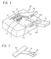
- FIG. 1 is a perspective view of an electronic device incorporating a memory card installing device according to a first embodiment of this invention, and a memory card to be installed.
- FIG. 2 is a perspective view of a plate spring applied to the memory card installing device of FIG. 1.
- FIG. 3 is a cross-sectional view showing a state of the memory card installing device of FIG. 1 in which the memory card is inserted and a lid is closed.
- FIG. 4 is a cross-sectional view showing a state of the memory card installing device of FIG. 1 in which the lid is opened to remove the memory.
- FIG. 5 is a cross-sectional view showing a state of the memory card installing device of FIG. 1 in which the lid is closed after the memory card is removed.
- FIG. 6 is a perspective view of a variation of the plate spring applied to the memory card installing device of FIG. 1.
- FIG. 7 is a perspective view of an electronic device incorporating a memory card installing device according to a second embodiment of this invention, and a memory card to be installed.
- FIG. 8 is a perspective view of a moving plate applied to the memory card installing device of FIG. 7.
- FIG. 9 is a cross-sectional view showing a state of the memory card installing device of FIG. 7 in which the memory card is inserted and a lid is completely closed.
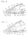
- FIG. 10 is a cross-sectional view showing a state of the memory card installing device of FIG. 7 in which the lid is being opened to remove the memory.
- FIG. 11 is a cross-sectional view showing a state of the memory card installing device of FIG. 7 in which the lid is completely opened to remove the memory.
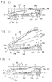
- FIG. 12 is a cross-sectional view showing a state of the memory card installing device of FIG. 7 in which the lid is closed after the memory card is removed.
- FIG. 13 is a cross-sectional view showing a state of the memory card installing device of FIG. 7 in which the lid is opened and the memory card is inserted.
- FIG. 14 is a cross-sectional view showing a state of the memory card installing device of FIG. 7 in which the lid is being closed after the state shown in FIG. 13.
- FIG. 1 is a perspective view of an electronic device 10 incorporating a memory card installing device according to a first embodiment of this invention, and a memory card 12 to be installed
- a main body 1 of the electronic device 10 is provided with a memory card installing portion 1a, and also with a connector portion 3 made of a conductive rubber or the like having conductive multilayers laminated at minute intervals and a conductivity in a predetermined direction (mainly a vertical direction.)
- the memory card installing portion 1a can be opened and closed by a lid 4 rotatably supported by an supporting shaft 5.
- the plate spring 6 is formed of an elastically deformable T-shaped thin plate and has a cover portion 6a which can cover a contacting surface 3a for contacting a connector portion 12c of the memory card 12 (see FIG. 3).
- the plate spring 6 has securing holes 6b for securing the plate spring 6 to the lid 4.
- FIG. 1 and FIGS. 3 to 5 show cross-sectional views of the installed or removed state of the memory card.
- a casing 11 of the device 10 is omitted in FIGS. 3 to 5.
- the memory card 12 is inserted in the electronic device 10 from a direction as shown in FIG. 1.
- a front end portion 12b of the memory card 12 is inserted in an inserting portion 1b of the main body 1 of the device 10 and the lid 4 is completely closed, as shown in the cross-sectional view of FIG. 3 showing the installed state of the memory card
- the front end portion 12b of the memory card 12 is supported by the inserting portion 1b of the main body 1 and the opposite end portion of the memory card 12 is pushed down by a pushing portion 4a of the lid 4.
- the connector portion 3 of the main body 1 and the connector portion 12c of the memory card 12 contact with each other at a predetermined position and are electrically connected.
- the lid 4 is maintained in the closed state of FIG. 3 by a locking member, such as a pawl or the like.
- the plate spring 6 interposes between the lid 4 and the memory card 12 and maintains its deformed state.
- the connector portion 3 of the main body 1 is always electrically connected with a printed board 2.
- the electronic device 10 can capture data of the memory card 12.
- the lid 4 When removing the memory card 12 from the installing portion 1a of the device 10, as shown in FIG. 4, the lid 4 is opened and the memory card 12 is removed.
- the memory card 12 can be easily removed because the memory card 12 is pushed down by the plate spring 6 and is spaced from the lid 4.
- the cover portion 6a of the plate spring 6 contacts and covers the contacting surface 3a of the connector portion 3 of the main body 1.
- the plate spring 6 is elastically deformed and the cover portion 6a contacts the connector portion 3 by a predetermined urging force.
- a gap will be seldom left between the contacting surface 3a and the cover portion 6a.
- the plate spring 6 is T-shaped, even if the plate spring 6 is not precisely parallel to the connecting surface 3a, the cover portion 6a fits to the contacting surface 3a so that the gap becomes minimal.
- FIG. 6 is a perspective view of a plate spring 16 which is a variation of the plate spring 6 shown in FIG. 2.
- This variation plate spring 16 is U-shaped and secured to the lid 4 by, for example, screw fasteners or the like and has a cover portion 16a which can cover the contacting surface 3a of the connector portion 3 of the main body 1.
- the variation plate spring 16 is also elastically deformed, and the cover portion 16a completely covers the contacting surface 3a of the connector portion 3.
- the connector portion 3 of the main body 1 of the electronic device can be protected from dust just by closing the lid 4 with the memory card 12 removed.
- FIG. 7 is a perspective view of an electronic device incorporating a memory card installing device 30 according to a second embodiment of this invention, and a memory card 32 to be installed.
- a memory card installing portion 21a provided in a main body 21 of the electronic device 30 is provided with a moving plate 28 which is a slidable and rotatable moving member.
- a connector portion 23 is arranged to abut on a printed board 22 (see FIG. 9).
- the structure of the connector 23 is the same as that of the connector portion 3 of the first embodiment.
- the memory card installing portion 21a can be opened and closed by a lid 24 rotatably supported by a supporting shaft 25.
- the lid 24 is provided on its installing portion side with a rotation lever 26 which is a connector cover member rotatably supported by a supporting shaft 27.
- the rotation lever 26 is provided on its connector portion side with a connector cover portion 26a for covering a contacting surface 23a of the connector portion 23, and on its memory card inserting side with a protrusion 26b.
- the moving plate 28 is provided in its central part with two pawl portions 28f which protrude downward and are bent to be L-shaped.
- the pawl portions 28f are engaged, slidably in the x-direction shown in FIG. 8, with supporting portions 21f which are edge portions of hole portions 21e provided in the installing portion 21a of the main body 21.
- the pawl portions 28f enable the moving plate 28 to rotate in the ⁇ -direction shown in FIG. 8.
- the moving plate 28 are provided, at its opposite ends on the side of the connector portion 23, with bent abutting portions 28g on which moving plate operating portions 24g (see FIG. 9) provided for the lid 24 can abut.
- the moving plate 28 is also provided on its memory card inserting side with two hook portions 28d bent inwardly so as to be U-shaped. The hook portions 28d are engageable with positioning recesses 32d of the memory card 32.
- two bent engaging projections 28i are provided in extended portions on both sides of the hook portions 28d of the moving plate 28.
- the engaging projections 28i can be selectively engaged with a first pair of lower steps 21i or a second pair of upper steps 21j provided in both side walls 21h of the main body 21.
- a pair of springs 29 are suspended between the walls 21h and the engaging projections 28i, and always urge the moving plate 28 in an upward slanting direction F shown in FIG. 9.
- FIG. 7 and FIGS. 9 to 14 show cross-sectional views of the installed or removed state of the memory card.
- a casing 31 of the device 30 is omitted in FIGS. 9 to 14.
- the lid 24 is opened and the memory card 32 is inserted in the installing portion 21a of the electronic device 30 from such a direction as shown in FIG. 7.
- a front end portion 32b of the memory card 32 is inserted in an inserting portion 21b of the main body 21 and the lid 24 is completely closed, as shown in the cross-sectional view of FIG. 9 showing the completely installed state, the front end portion 32b of the memory card 32 is supported by the inserting portion 21b and the opposite end portion of the memory card 32 is pushed down by a pushing portion 24a of the lid 24.
- the moving plate 28 is pushed down by the memory card 32 and disengages from the second steps 21j to slide backwards (toward the connector portion side) due to the urging force of the springs 29.
- the engaging projections 28i engage with the first steps 21i of the walls 21h and the ends of the hook portions 28d fit in the recesses 32d of the memory card 32 to determine the position of the memory card 32.
- the contacting surface 23a of the connector portion 23 of the main body 21 and the connector 32c of the memory card 32 are pressed to contact with each other and electrically connected.
- the electronic device 30 can transmit and receive data to and from the memory card 32.
- the lid 24 is maintained in the closed state of FIG. 9 by a locking member such as a pawl or the like provided to the lid 24.
- the lid 24 is opened. While the lid 24 is being opened, the operating portions 24g of the lid 24 pushes and moves the bent abutting portions 28g forward against the urging force F of the springs 29. The movement causes the hook portions 28d of the moving plate 28 to disengage from the recesses 32d of the memory card 32.
- the memory card 32 is lifted by a pushingforce caused by elastic deformation of the connector portion 23, as shown in FIG. 10.
- the moving plate 28 is further moved forward by the operating portions 24g until the lid 24 is completely opened.
- the projections 28i of the moving plate 28 disengage from the first steps 21i and engage with the second steps 21j and the moving plate 28 rotates in a counterclockwise direction.
- the rotation is made against the urging force F of the springs 29 with the pawls 28f being the center of rotation. This rotation causes the bent abutting portions 28g to disengage from the operating portions 24g.
- the lid 24 is closed, as shown in FIG. 12. At this time, the pushing protrusion 26b of the rotation lever 26 is pushed against the end of the hook portions 28d of the moving plate 28 engaging with the second steps 21j.
- the connector cover portion 26a on the opposite side covers the contacting surface 23a of the connector portion 23 of the main body 21 without any gap therebetween.
- FIG. 14 shows a state immediately before the lid 24 is completely closed.
- the memory card 32 pushed by the pushing protrusion 24a pushes the moving plate 28.
- the moving plate 28 rotates clockwise against the urging force of the springs 29 with the pawl portions 28f being the center of rotation, so that the engaging projections 28i are going to disengage from the second steps 21j.
- the memory card installing device When the lid 24 is completely closed, the memory card installing device is in the state shown in FIG. 9.
- the projections 28i of the moving plate 28 disengage from the second steps 21j to slide backward (toward the connector portion 23), and then engage with the first steps 21i.
- the hook portions 28d fit into the recesses 32d of the memory card 12 to define the position of the memory card 32.
- the connector portion 23 of the main body 21 and the connector portion 32c of the memory card 32 are pressed to contact with each other and are electrically connected.
- the connector portion 23 of the main body 21 can be protected from dust by closing the lid 24 with the memory card 32 removed.
Abstract
A memory card installing device has a memory card installing portion having a connector; a lid for opening and closing the memory card installing portion; and a connector cover for covering the connector when the memory card is not installed in a predetermined position and the lid is closed.
Description
- This invention relates to a memory card installing device.
- Recently, various kinds of electronic devices utilizing a removable memory card incorporating a solid-state memory are on the market and used by users in general. Such electronic devices are provided with a multi-contact connector portion in which the connector of the memory card is installed. The contacts are made of gold or the like.
- When the connector portion of the memory card is inserted in the contact connector portion, electrical connection is made so that information can be transmitted between the memory card and the electronic device.
- However, the memory card is not always installed in the electronic device. The electronic device may be used or stored without the memory card. Even though the electronic device is provided with a casing cover for protecting the memory card, there is not a protective cover directly covering the contact connector portion.
- Thus, when the memory card is removed for a long time, dust may settle on the contacts of the connector of the electronic device. When the memory card is replaced to the connector portion, it may be impossible to transmit information to and from the memory card, if any contact fails to contact because of the dust.
- An object of this invention is to provide a memory card installing device which can prevent, by simple structure, dust from entering into a connector portion when a memory card is not installed.
- According to this invention, a device for installing a memory card comprises a memory card installing portion having a connector portion; a lid for opening and closing the memory card installing portion; and a connector cover member for covering the connector portion when the memory card is not installed at a predetermined position and the lid is closed.
- FIG. 1 is a perspective view of an electronic device incorporating a memory card installing device according to a first embodiment of this invention, and a memory card to be installed.
- FIG. 2 is a perspective view of a plate spring applied to the memory card installing device of FIG. 1.
- FIG. 3 is a cross-sectional view showing a state of the memory card installing device of FIG. 1 in which the memory card is inserted and a lid is closed.
- FIG. 4 is a cross-sectional view showing a state of the memory card installing device of FIG. 1 in which the lid is opened to remove the memory.
- FIG. 5 is a cross-sectional view showing a state of the memory card installing device of FIG. 1 in which the lid is closed after the memory card is removed.
- FIG. 6 is a perspective view of a variation of the plate spring applied to the memory card installing device of FIG. 1.
- FIG. 7 is a perspective view of an electronic device incorporating a memory card installing device according to a second embodiment of this invention, and a memory card to be installed.
- FIG. 8 is a perspective view of a moving plate applied to the memory card installing device of FIG. 7.
- FIG. 9 is a cross-sectional view showing a state of the memory card installing device of FIG. 7 in which the memory card is inserted and a lid is completely closed.
- FIG. 10 is a cross-sectional view showing a state of the memory card installing device of FIG. 7 in which the lid is being opened to remove the memory.
- FIG. 11 is a cross-sectional view showing a state of the memory card installing device of FIG. 7 in which the lid is completely opened to remove the memory.
- FIG. 12 is a cross-sectional view showing a state of the memory card installing device of FIG. 7 in which the lid is closed after the memory card is removed.
- FIG. 13 is a cross-sectional view showing a state of the memory card installing device of FIG. 7 in which the lid is opened and the memory card is inserted.
- FIG. 14 is a cross-sectional view showing a state of the memory card installing device of FIG. 7 in which the lid is being closed after the state shown in FIG. 13.
- Referring to the drawings, embodiments of this invention will now be described.
- FIG. 1 is a perspective view of an
electronic device 10 incorporating a memory card installing device according to a first embodiment of this invention, and amemory card 12 to be installed - A
main body 1 of theelectronic device 10 is provided with a memory card installing portion 1a, and also with aconnector portion 3 made of a conductive rubber or the like having conductive multilayers laminated at minute intervals and a conductivity in a predetermined direction (mainly a vertical direction.) The memory card installing portion 1a can be opened and closed by alid 4 rotatably supported by an supportingshaft 5. - A
plate spring 6, which is an elastic member, is secured to thelid 4 on the side of the installing portion 1a. As shown in a perspective view of FIG. 2, theplate spring 6 is formed of an elastically deformable T-shaped thin plate and has acover portion 6a which can cover a contactingsurface 3a for contacting aconnector portion 12c of the memory card 12 (see FIG. 3). Theplate spring 6 has securingholes 6b for securing theplate spring 6 to thelid 4. - Next, the operation of installing and removing the
memory card 12 in and from theelectronic device 10 thus constructed is described, referring to FIG. 1 and FIGS. 3 to 5 which show cross-sectional views of the installed or removed state of the memory card. Acasing 11 of thedevice 10 is omitted in FIGS. 3 to 5. - With the
lid 4 opened, thememory card 12 is inserted in theelectronic device 10 from a direction as shown in FIG. 1. When afront end portion 12b of thememory card 12 is inserted in aninserting portion 1b of themain body 1 of thedevice 10 and thelid 4 is completely closed, as shown in the cross-sectional view of FIG. 3 showing the installed state of the memory card, thefront end portion 12b of thememory card 12 is supported by the insertingportion 1b of themain body 1 and the opposite end portion of thememory card 12 is pushed down by a pushingportion 4a of thelid 4. Thus, theconnector portion 3 of themain body 1 and theconnector portion 12c of thememory card 12 contact with each other at a predetermined position and are electrically connected. Thelid 4 is maintained in the closed state of FIG. 3 by a locking member, such as a pawl or the like. Theplate spring 6 interposes between thelid 4 and thememory card 12 and maintains its deformed state. - The
connector portion 3 of themain body 1 is always electrically connected with a printedboard 2. When thememory card 12 is installed, theelectronic device 10 can capture data of thememory card 12. - When removing the
memory card 12 from the installing portion 1a of thedevice 10, as shown in FIG. 4, thelid 4 is opened and thememory card 12 is removed. Thememory card 12 can be easily removed because thememory card 12 is pushed down by theplate spring 6 and is spaced from thelid 4. - After the
memory card 12 is removed and thelid 4 is closed, as shown in FIG. 5, thecover portion 6a of theplate spring 6 contacts and covers the contactingsurface 3a of theconnector portion 3 of themain body 1. At this time, theplate spring 6 is elastically deformed and thecover portion 6a contacts theconnector portion 3 by a predetermined urging force. Thus, a gap will be seldom left between the contactingsurface 3a and thecover portion 6a. Further, because theplate spring 6 is T-shaped, even if theplate spring 6 is not precisely parallel to the connectingsurface 3a, thecover portion 6a fits to the contactingsurface 3a so that the gap becomes minimal. - Therefore, even if the
electronic device 10 is stored or used for a long time without thememory card 12 inserted, dust will not settle on the contactingsurface 3a. Thus, when thelid 4 is opened again and thememory card 12 is installed, theelectronic device 10 can be operated normally. - FIG. 6 is a perspective view of a
plate spring 16 which is a variation of theplate spring 6 shown in FIG. 2. Thisvariation plate spring 16 is U-shaped and secured to thelid 4 by, for example, screw fasteners or the like and has a cover portion 16a which can cover the contactingsurface 3a of theconnector portion 3 of themain body 1. When thelid 4 is closed with thememory card 12 removed, thevariation plate spring 16 is also elastically deformed, and the cover portion 16a completely covers the contactingsurface 3a of theconnector portion 3. - Therefore, the
connector portion 3 of themain body 1 of the electronic device can be protected from dust just by closing thelid 4 with thememory card 12 removed. - FIG. 7 is a perspective view of an electronic device incorporating a memory
card installing device 30 according to a second embodiment of this invention, and amemory card 32 to be installed. - As shown in FIG. 7, a memory
card installing portion 21a provided in amain body 21 of theelectronic device 30 is provided with a movingplate 28 which is a slidable and rotatable moving member. Aconnector portion 23 is arranged to abut on a printed board 22 (see FIG. 9). The structure of theconnector 23 is the same as that of theconnector portion 3 of the first embodiment. The memorycard installing portion 21a can be opened and closed by alid 24 rotatably supported by a supportingshaft 25. - The
lid 24 is provided on its installing portion side with arotation lever 26 which is a connector cover member rotatably supported by a supportingshaft 27. Therotation lever 26 is provided on its connector portion side with aconnector cover portion 26a for covering a contactingsurface 23a of theconnector portion 23, and on its memory card inserting side with aprotrusion 26b. - As shown in a perspective view of FIG. 8 and a cross-sectional view of FIG. 9, the moving
plate 28 is provided in its central part with twopawl portions 28f which protrude downward and are bent to be L-shaped. Thepawl portions 28f are engaged, slidably in the x-direction shown in FIG. 8, with supportingportions 21f which are edge portions ofhole portions 21e provided in the installingportion 21a of themain body 21. At the same time, thepawl portions 28f enable the movingplate 28 to rotate in the θ-direction shown in FIG. 8. - The moving
plate 28 are provided, at its opposite ends on the side of theconnector portion 23, withbent abutting portions 28g on which movingplate operating portions 24g (see FIG. 9) provided for thelid 24 can abut. The movingplate 28 is also provided on its memory card inserting side with twohook portions 28d bent inwardly so as to be U-shaped. Thehook portions 28d are engageable withpositioning recesses 32d of thememory card 32. - Further, two bent
engaging projections 28i are provided in extended portions on both sides of thehook portions 28d of the movingplate 28. In accordance with the position of the movingplate 28, the engagingprojections 28i can be selectively engaged with a first pair oflower steps 21i or a second pair ofupper steps 21j provided in bothside walls 21h of themain body 21. - A pair of
springs 29 are suspended between thewalls 21h and the engagingprojections 28i, and always urge the movingplate 28 in an upward slanting direction F shown in FIG. 9. - Next, the operation of installing and removing the
memory card 32 in and from theelectronic device 30 thus constructed is described, referring to FIG. 7 and FIGS. 9 to 14 which show cross-sectional views of the installed or removed state of the memory card. Acasing 31 of thedevice 30 is omitted in FIGS. 9 to 14. - When the
memory card 32 is installed, thelid 24 is opened and thememory card 32 is inserted in the installingportion 21a of theelectronic device 30 from such a direction as shown in FIG. 7. When afront end portion 32b of thememory card 32 is inserted in an insertingportion 21b of themain body 21 and thelid 24 is completely closed, as shown in the cross-sectional view of FIG. 9 showing the completely installed state, thefront end portion 32b of thememory card 32 is supported by the insertingportion 21b and the opposite end portion of thememory card 32 is pushed down by a pushingportion 24a of thelid 24. Further, the movingplate 28 is pushed down by thememory card 32 and disengages from thesecond steps 21j to slide backwards (toward the connector portion side) due to the urging force of thesprings 29. The engagingprojections 28i engage with thefirst steps 21i of thewalls 21h and the ends of thehook portions 28d fit in therecesses 32d of thememory card 32 to determine the position of thememory card 32. - When the
memory card 32 is installed in the predetermined position, the contactingsurface 23a of theconnector portion 23 of themain body 21 and theconnector 32c of thememory card 32 are pressed to contact with each other and electrically connected. Thus, theelectronic device 30 can transmit and receive data to and from thememory card 32. Thelid 24 is maintained in the closed state of FIG. 9 by a locking member such as a pawl or the like provided to thelid 24. - Next, when the
memory card 32 is removed from theelectronic device 30, as shown in FIG. 10, thelid 24 is opened. While thelid 24 is being opened, the operatingportions 24g of thelid 24 pushes and moves the bent abuttingportions 28g forward against the urging force F of thesprings 29. The movement causes thehook portions 28d of the movingplate 28 to disengage from therecesses 32d of thememory card 32. Thememory card 32 is lifted by a pushingforce caused by elastic deformation of theconnector portion 23, as shown in FIG. 10. - The moving
plate 28 is further moved forward by the operatingportions 24g until thelid 24 is completely opened. As shown in FIG. 11, theprojections 28i of the movingplate 28 disengage from thefirst steps 21i and engage with thesecond steps 21j and the movingplate 28 rotates in a counterclockwise direction. The rotation is made against the urging force F of thesprings 29 with thepawls 28f being the center of rotation. This rotation causes thebent abutting portions 28g to disengage from the operatingportions 24g. - After the
memory card 32 is removed with thelid 24 open, thelid 24 is closed, as shown in FIG. 12. At this time, the pushingprotrusion 26b of therotation lever 26 is pushed against the end of thehook portions 28d of the movingplate 28 engaging with thesecond steps 21j. Theconnector cover portion 26a on the opposite side covers the contactingsurface 23a of theconnector portion 23 of themain body 21 without any gap therebetween. - In order to install the
memory card 32, thelid 24 is opened and thefront end portion 32b of thememory card 32 is inserted in the insertingportion 21b of themain body 21, as shown in FIG. 13. Then thelid 24 is closed. FIG. 14 shows a state immediately before thelid 24 is completely closed. Thememory card 32 pushed by the pushingprotrusion 24a pushes the movingplate 28. The movingplate 28 rotates clockwise against the urging force of thesprings 29 with thepawl portions 28f being the center of rotation, so that the engagingprojections 28i are going to disengage from thesecond steps 21j. - When the
lid 24 is completely closed, the memory card installing device is in the state shown in FIG. 9. Theprojections 28i of the movingplate 28 disengage from thesecond steps 21j to slide backward (toward the connector portion 23), and then engage with thefirst steps 21i. Thus, thehook portions 28d fit into therecesses 32d of thememory card 12 to define the position of thememory card 32. Theconnector portion 23 of themain body 21 and theconnector portion 32c of thememory card 32 are pressed to contact with each other and are electrically connected. - Thus, the
connector portion 23 of themain body 21 can be protected from dust by closing thelid 24 with thememory card 32 removed.
Claims (10)
- A device for installing a memory card, comprising:a memory card installing portion having a connector portion;a lid for opening and closing the memory card installing portion; anda connector cover member for covering the connector portion when the memory card is not installed in a predetermined position and the lid is closed.
- The device according to claim 1, wherein the connector cover member is provided to the lid.
- The device according to claim 2, wherein the connector cover member is an elastic member interposing between the memory card and the lid when the memory card is installed in the predetermined position, and covering the connector portion when the memory card is not installed in the predetermined position and the lid is closed.
- The device according to claim 3, wherein the elastic member is elastically deformed to push the connector portion when the elastic member covers the connector portion.
- The device according to claim 3, wherein the elastic member separates the memory card from the lid when the lid is open.
- The device according to claim 4, wherein the elastic member separates the memory card from the lid when the lid when the lid is open.
- The device according to claim 2, further comprising a moving member which is in different positions depending on whether the memory card is installed in the predetermined position or not, wherein the connector cover member is rotatably provided to the lid, and when the lid is closed without the memory card installed, the moving member is moved to a predetermined position to push and rotate the connector cover member to cover the connector portion.
- The device according to claim 7, wherein the moving member comprises a hook member for positioning the memory card when the memory card is installed in the predetermined position.
- The device according to claim 7, wherein the moving member is slidable and rotatable.
- The device according to claim 8, wherein the moving member is slidable and rotatable.
Applications Claiming Priority (6)
| Application Number | Priority Date | Filing Date | Title |
|---|---|---|---|
| JP105740/96 | 1996-04-25 | ||
| JP8105740A JPH09293552A (en) | 1996-04-25 | 1996-04-25 | Memory card mounting device |
| JP105739/96 | 1996-04-25 | ||
| JP10574096 | 1996-04-25 | ||
| JP10573996 | 1996-04-25 | ||
| JP8105739A JPH09293551A (en) | 1996-04-25 | 1996-04-25 | Memory card mounting device |
Publications (2)
| Publication Number | Publication Date |
|---|---|
| EP0803834A2 true EP0803834A2 (en) | 1997-10-29 |
| EP0803834A3 EP0803834A3 (en) | 2000-06-28 |
Family
ID=26445976
Family Applications (1)
| Application Number | Title | Priority Date | Filing Date |
|---|---|---|---|
| EP97106336A Withdrawn EP0803834A3 (en) | 1996-04-25 | 1997-04-17 | Memory card installing device |
Country Status (2)
| Country | Link |
|---|---|
| US (1) | US5822183A (en) |
| EP (1) | EP0803834A3 (en) |
Cited By (2)
| Publication number | Priority date | Publication date | Assignee | Title |
|---|---|---|---|---|
| FR2844642A1 (en) * | 2002-09-12 | 2004-03-19 | Itt Mfg Enterprises Inc | High storage capacity integrated circuit card electrical connector having memory card lower face contact ends and conductor plane near crossing edge holder and having upper locking element. |
| CN107611675A (en) * | 2017-07-31 | 2018-01-19 | 合肥隆延科技有限公司 | A kind of smart home wiring board |
Families Citing this family (25)
| Publication number | Priority date | Publication date | Assignee | Title |
|---|---|---|---|---|
| US5933328A (en) * | 1998-07-28 | 1999-08-03 | Sandisk Corporation | Compact mechanism for removable insertion of multiple integrated circuit cards into portable and other electronic devices |
| US6240301B1 (en) * | 1998-10-29 | 2001-05-29 | Ericcson Inc. | Diversity antenna in a SIM card package |
| US6483698B1 (en) * | 1998-11-27 | 2002-11-19 | Hewlett-Packard Company | Cradle for supporting a PDA and similar portable electronic devices |
| TW475743U (en) * | 2000-09-01 | 2002-02-01 | Hon Hai Prec Ind Co Ltd | Computer panel |
| ES1049362Y (en) * | 2001-06-01 | 2002-04-16 | Lear Automotive Eeds Spain | PERFECTED ANCHORAGE DEVICE FOR CONNECTOR BOX IN SERVICE BOXES. |
| JP4789362B2 (en) * | 2001-07-25 | 2011-10-12 | 富士機械製造株式会社 | Substrate holding device |
| US6766952B2 (en) * | 2001-11-06 | 2004-07-27 | Quadnovation, Inc. | SIM card carrier |
| AU2003240938A1 (en) * | 2002-05-31 | 2003-12-19 | Simpletech, Inc. | Removable storage device |
| US7462044B1 (en) * | 2004-07-29 | 2008-12-09 | Ennova Direct, Inc. | Thumb drive with retractable USB connector |
| TWI316713B (en) * | 2004-09-10 | 2009-11-01 | Murata Manufacturing Co | Card-type device |
| US7264491B2 (en) * | 2006-01-06 | 2007-09-04 | Apple, Inc. | Method and apparatus for linear insertion and removal of a memory module in a computer system |
| US7416417B2 (en) * | 2006-04-06 | 2008-08-26 | Utstarcom, Inc. | Connector alignment system for a highly integrated, installable miniaturized form factor card for wireless communications functions |
| US7416450B2 (en) * | 2006-04-06 | 2008-08-26 | Utstarcom, Inc. | Connector for a highly integrated, installable miniaturized form factor card for wireless communications functions |
| US20090017649A1 (en) * | 2007-07-10 | 2009-01-15 | Utstarcom | Method and apparatus for reduction of external elastomeric connector compression force |
| US9616120B2 (en) * | 2010-03-04 | 2017-04-11 | Vet Therapeutics, Inc. | Monoclonal antibodies directed to CD20 |
| DE102010002947A1 (en) * | 2010-03-17 | 2011-09-22 | Robert Bosch Gmbh | control unit |
| CN102447175B (en) * | 2010-09-30 | 2014-09-03 | 联想(北京)有限公司 | Electronic equipment |
| US9007757B2 (en) | 2010-03-30 | 2015-04-14 | Beijing Lenovo Software Ltd. | Information processing device |
| KR101880181B1 (en) * | 2011-07-21 | 2018-07-19 | 삼성전자주식회사 | Insert type card retracting/extending apparatus for electronic device |
| TWI422107B (en) * | 2011-09-06 | 2014-01-01 | Inventec Corp | Cover plate structure |
| TWM468701U (en) * | 2013-06-06 | 2013-12-21 | Celestica Int Inc | PCI card fixing system |
| JP5948312B2 (en) * | 2013-12-19 | 2016-07-06 | 株式会社フジクラ | Cage, communication device, communication module, and connection method |
| CN106462195A (en) * | 2014-08-22 | 2017-02-22 | 谷歌公司 | Systems for module interfacing of modular mobile electronic devices |
| DE102014220893A1 (en) * | 2014-10-15 | 2016-04-21 | Te Connectivity Germany Gmbh | Plug element, mating connector element and electrical connector |
| US10490943B2 (en) * | 2017-08-09 | 2019-11-26 | Micron Technology, Inc. | Securing a memory card |
Citations (2)
| Publication number | Priority date | Publication date | Assignee | Title |
|---|---|---|---|---|
| US4780604A (en) * | 1986-02-21 | 1988-10-25 | Kabushiki Kaisha Toshiba | IC-incorporated memory card |
| GB2258748A (en) * | 1991-08-01 | 1993-02-17 | John Wolfgang Halpern | Pocketsize data reader for chip cards |
Family Cites Families (6)
| Publication number | Priority date | Publication date | Assignee | Title |
|---|---|---|---|---|
| US4775327A (en) * | 1987-02-17 | 1988-10-04 | Amphenol Corporation | Connector with automatic protection cap |
| US4940414A (en) * | 1988-09-20 | 1990-07-10 | Namsung Electronics Corp. | Antitheft car audio set with removable control box |
| JPH02222087A (en) * | 1989-02-23 | 1990-09-04 | Toshiba Corp | Recording medium connecting device |
| US5408384A (en) * | 1993-05-13 | 1995-04-18 | Matsushita Electric Industrial Co., Ltd. | Electronic card and connector device therefor |
| US5559672A (en) * | 1994-12-05 | 1996-09-24 | Compaq Computer Corporation | Door apparatus for a portable computer |
| JP3019280U (en) * | 1995-05-18 | 1995-12-12 | モレックス インコーポレーテッド | IC card holder |
-
1997
- 1997-04-17 EP EP97106336A patent/EP0803834A3/en not_active Withdrawn
- 1997-04-23 US US08/842,127 patent/US5822183A/en not_active Expired - Fee Related
Patent Citations (2)
| Publication number | Priority date | Publication date | Assignee | Title |
|---|---|---|---|---|
| US4780604A (en) * | 1986-02-21 | 1988-10-25 | Kabushiki Kaisha Toshiba | IC-incorporated memory card |
| GB2258748A (en) * | 1991-08-01 | 1993-02-17 | John Wolfgang Halpern | Pocketsize data reader for chip cards |
Cited By (4)
| Publication number | Priority date | Publication date | Assignee | Title |
|---|---|---|---|---|
| FR2844642A1 (en) * | 2002-09-12 | 2004-03-19 | Itt Mfg Enterprises Inc | High storage capacity integrated circuit card electrical connector having memory card lower face contact ends and conductor plane near crossing edge holder and having upper locking element. |
| WO2004025788A1 (en) * | 2002-09-12 | 2004-03-25 | Itt Manufacturing Enterprises, Inc. | Electrical connector for a smart card having a high storage capacity |
| US7048589B2 (en) | 2002-09-12 | 2006-05-23 | Itt Manufacturing Enterprises, Inc. | Short smart card connector |
| CN107611675A (en) * | 2017-07-31 | 2018-01-19 | 合肥隆延科技有限公司 | A kind of smart home wiring board |
Also Published As
| Publication number | Publication date |
|---|---|
| EP0803834A3 (en) | 2000-06-28 |
| US5822183A (en) | 1998-10-13 |
Similar Documents
| Publication | Publication Date | Title |
|---|---|---|
| US5822183A (en) | Memory card installing device | |
| EP1355384B1 (en) | Card connector reduced in operating force | |
| EP1760841B1 (en) | Memory card socket structure | |
| US20070093132A1 (en) | Electrical card connector with shutter mechanism | |
| WO1998043199A1 (en) | Card reader connector having a separable cover | |
| EP0959423B1 (en) | Card connector | |
| JP3327178B2 (en) | connector | |
| JP3250789B2 (en) | Electrical connector for cards with surface contacts | |
| JP3368465B2 (en) | IC card connector | |
| US8062048B2 (en) | Electrical connector with pivotally movable cover | |
| JP4175313B2 (en) | Package with locking mechanism and optical transceiver | |
| EP1548897B1 (en) | Card connector that can prevent both leaping-out and ejection failure of a card | |
| JP4474355B2 (en) | Card connector device | |
| US7503500B2 (en) | Card connector with anti-mismating device | |
| JP3546387B2 (en) | connector | |
| JP4527887B2 (en) | Card connector erroneous insertion prevention device | |
| JP2776780B2 (en) | Card edge connector with latch mechanism | |
| JP5013299B2 (en) | Card connector | |
| US6860747B2 (en) | System and method for mounting a processor | |
| JP3920807B2 (en) | Card connector device | |
| US20060258203A1 (en) | Card Connector | |
| JPH09293551A (en) | Memory card mounting device | |
| JP2516430Y2 (en) | Memory card connector | |
| JP3541813B2 (en) | IC package and assembling method thereof | |
| JP2003142205A (en) | Card connector |
Legal Events
| Date | Code | Title | Description |
|---|---|---|---|
| PUAI | Public reference made under article 153(3) epc to a published international application that has entered the european phase |
Free format text: ORIGINAL CODE: 0009012 |
|
| AK | Designated contracting states |
Kind code of ref document: A2 Designated state(s): DE FR GB |
|
| PUAL | Search report despatched |
Free format text: ORIGINAL CODE: 0009013 |
|
| AK | Designated contracting states |
Kind code of ref document: A3 Designated state(s): DE FR GB |
|
| RIC1 | Information provided on ipc code assigned before grant |
Free format text: 7G 06K 7/06 A, 7H 01R 13/447 B, 7G 06K 7/00 B |
|
| STAA | Information on the status of an ep patent application or granted ep patent |
Free format text: STATUS: THE APPLICATION IS DEEMED TO BE WITHDRAWN |
|
| 18D | Application deemed to be withdrawn |
Effective date: 20001229 |