EP0804035A2 - Moving picture encoding apparatus and method - Google Patents
Moving picture encoding apparatus and method Download PDFInfo
- Publication number
- EP0804035A2 EP0804035A2 EP97106862A EP97106862A EP0804035A2 EP 0804035 A2 EP0804035 A2 EP 0804035A2 EP 97106862 A EP97106862 A EP 97106862A EP 97106862 A EP97106862 A EP 97106862A EP 0804035 A2 EP0804035 A2 EP 0804035A2
- Authority
- EP
- European Patent Office
- Prior art keywords
- encoding
- picture
- bits
- image segment
- generated
- Prior art date
- Legal status (The legal status is an assumption and is not a legal conclusion. Google has not performed a legal analysis and makes no representation as to the accuracy of the status listed.)
- Granted
Links
Images


Classifications
-
- H—ELECTRICITY
- H04—ELECTRIC COMMUNICATION TECHNIQUE
- H04N—PICTORIAL COMMUNICATION, e.g. TELEVISION
- H04N19/00—Methods or arrangements for coding, decoding, compressing or decompressing digital video signals
- H04N19/85—Methods or arrangements for coding, decoding, compressing or decompressing digital video signals using pre-processing or post-processing specially adapted for video compression
- H04N19/87—Methods or arrangements for coding, decoding, compressing or decompressing digital video signals using pre-processing or post-processing specially adapted for video compression involving scene cut or scene change detection in combination with video compression
-
- H—ELECTRICITY
- H04—ELECTRIC COMMUNICATION TECHNIQUE
- H04N—PICTORIAL COMMUNICATION, e.g. TELEVISION
- H04N19/00—Methods or arrangements for coding, decoding, compressing or decompressing digital video signals
- H04N19/10—Methods or arrangements for coding, decoding, compressing or decompressing digital video signals using adaptive coding
- H04N19/102—Methods or arrangements for coding, decoding, compressing or decompressing digital video signals using adaptive coding characterised by the element, parameter or selection affected or controlled by the adaptive coding
- H04N19/124—Quantisation
- H04N19/126—Details of normalisation or weighting functions, e.g. normalisation matrices or variable uniform quantisers
-
- H—ELECTRICITY
- H04—ELECTRIC COMMUNICATION TECHNIQUE
- H04N—PICTORIAL COMMUNICATION, e.g. TELEVISION
- H04N19/00—Methods or arrangements for coding, decoding, compressing or decompressing digital video signals
- H04N19/10—Methods or arrangements for coding, decoding, compressing or decompressing digital video signals using adaptive coding
- H04N19/102—Methods or arrangements for coding, decoding, compressing or decompressing digital video signals using adaptive coding characterised by the element, parameter or selection affected or controlled by the adaptive coding
- H04N19/132—Sampling, masking or truncation of coding units, e.g. adaptive resampling, frame skipping, frame interpolation or high-frequency transform coefficient masking
-
- H—ELECTRICITY
- H04—ELECTRIC COMMUNICATION TECHNIQUE
- H04N—PICTORIAL COMMUNICATION, e.g. TELEVISION
- H04N19/00—Methods or arrangements for coding, decoding, compressing or decompressing digital video signals
- H04N19/10—Methods or arrangements for coding, decoding, compressing or decompressing digital video signals using adaptive coding
- H04N19/134—Methods or arrangements for coding, decoding, compressing or decompressing digital video signals using adaptive coding characterised by the element, parameter or criterion affecting or controlling the adaptive coding
- H04N19/136—Incoming video signal characteristics or properties
- H04N19/14—Coding unit complexity, e.g. amount of activity or edge presence estimation
-
- H—ELECTRICITY
- H04—ELECTRIC COMMUNICATION TECHNIQUE
- H04N—PICTORIAL COMMUNICATION, e.g. TELEVISION
- H04N19/00—Methods or arrangements for coding, decoding, compressing or decompressing digital video signals
- H04N19/10—Methods or arrangements for coding, decoding, compressing or decompressing digital video signals using adaptive coding
- H04N19/134—Methods or arrangements for coding, decoding, compressing or decompressing digital video signals using adaptive coding characterised by the element, parameter or criterion affecting or controlling the adaptive coding
- H04N19/142—Detection of scene cut or scene change
-
- H—ELECTRICITY
- H04—ELECTRIC COMMUNICATION TECHNIQUE
- H04N—PICTORIAL COMMUNICATION, e.g. TELEVISION
- H04N19/00—Methods or arrangements for coding, decoding, compressing or decompressing digital video signals
- H04N19/10—Methods or arrangements for coding, decoding, compressing or decompressing digital video signals using adaptive coding
- H04N19/134—Methods or arrangements for coding, decoding, compressing or decompressing digital video signals using adaptive coding characterised by the element, parameter or criterion affecting or controlling the adaptive coding
- H04N19/146—Data rate or code amount at the encoder output
- H04N19/149—Data rate or code amount at the encoder output by estimating the code amount by means of a model, e.g. mathematical model or statistical model
-
- H—ELECTRICITY
- H04—ELECTRIC COMMUNICATION TECHNIQUE
- H04N—PICTORIAL COMMUNICATION, e.g. TELEVISION
- H04N19/00—Methods or arrangements for coding, decoding, compressing or decompressing digital video signals
- H04N19/10—Methods or arrangements for coding, decoding, compressing or decompressing digital video signals using adaptive coding
- H04N19/134—Methods or arrangements for coding, decoding, compressing or decompressing digital video signals using adaptive coding characterised by the element, parameter or criterion affecting or controlling the adaptive coding
- H04N19/146—Data rate or code amount at the encoder output
- H04N19/15—Data rate or code amount at the encoder output by monitoring actual compressed data size at the memory before deciding storage at the transmission buffer
-
- H—ELECTRICITY
- H04—ELECTRIC COMMUNICATION TECHNIQUE
- H04N—PICTORIAL COMMUNICATION, e.g. TELEVISION
- H04N19/00—Methods or arrangements for coding, decoding, compressing or decompressing digital video signals
- H04N19/10—Methods or arrangements for coding, decoding, compressing or decompressing digital video signals using adaptive coding
- H04N19/169—Methods or arrangements for coding, decoding, compressing or decompressing digital video signals using adaptive coding characterised by the coding unit, i.e. the structural portion or semantic portion of the video signal being the object or the subject of the adaptive coding
- H04N19/17—Methods or arrangements for coding, decoding, compressing or decompressing digital video signals using adaptive coding characterised by the coding unit, i.e. the structural portion or semantic portion of the video signal being the object or the subject of the adaptive coding the unit being an image region, e.g. an object
- H04N19/172—Methods or arrangements for coding, decoding, compressing or decompressing digital video signals using adaptive coding characterised by the coding unit, i.e. the structural portion or semantic portion of the video signal being the object or the subject of the adaptive coding the unit being an image region, e.g. an object the region being a picture, frame or field
-
- H—ELECTRICITY
- H04—ELECTRIC COMMUNICATION TECHNIQUE
- H04N—PICTORIAL COMMUNICATION, e.g. TELEVISION
- H04N19/00—Methods or arrangements for coding, decoding, compressing or decompressing digital video signals
- H04N19/10—Methods or arrangements for coding, decoding, compressing or decompressing digital video signals using adaptive coding
- H04N19/169—Methods or arrangements for coding, decoding, compressing or decompressing digital video signals using adaptive coding characterised by the coding unit, i.e. the structural portion or semantic portion of the video signal being the object or the subject of the adaptive coding
- H04N19/177—Methods or arrangements for coding, decoding, compressing or decompressing digital video signals using adaptive coding characterised by the coding unit, i.e. the structural portion or semantic portion of the video signal being the object or the subject of the adaptive coding the unit being a group of pictures [GOP]
-
- H—ELECTRICITY
- H04—ELECTRIC COMMUNICATION TECHNIQUE
- H04N—PICTORIAL COMMUNICATION, e.g. TELEVISION
- H04N19/00—Methods or arrangements for coding, decoding, compressing or decompressing digital video signals
- H04N19/10—Methods or arrangements for coding, decoding, compressing or decompressing digital video signals using adaptive coding
- H04N19/169—Methods or arrangements for coding, decoding, compressing or decompressing digital video signals using adaptive coding characterised by the coding unit, i.e. the structural portion or semantic portion of the video signal being the object or the subject of the adaptive coding
- H04N19/179—Methods or arrangements for coding, decoding, compressing or decompressing digital video signals using adaptive coding characterised by the coding unit, i.e. the structural portion or semantic portion of the video signal being the object or the subject of the adaptive coding the unit being a scene or a shot
-
- H—ELECTRICITY
- H04—ELECTRIC COMMUNICATION TECHNIQUE
- H04N—PICTORIAL COMMUNICATION, e.g. TELEVISION
- H04N19/00—Methods or arrangements for coding, decoding, compressing or decompressing digital video signals
- H04N19/60—Methods or arrangements for coding, decoding, compressing or decompressing digital video signals using transform coding
- H04N19/61—Methods or arrangements for coding, decoding, compressing or decompressing digital video signals using transform coding in combination with predictive coding
-
- H—ELECTRICITY
- H04—ELECTRIC COMMUNICATION TECHNIQUE
- H04N—PICTORIAL COMMUNICATION, e.g. TELEVISION
- H04N19/00—Methods or arrangements for coding, decoding, compressing or decompressing digital video signals
- H04N19/10—Methods or arrangements for coding, decoding, compressing or decompressing digital video signals using adaptive coding
- H04N19/102—Methods or arrangements for coding, decoding, compressing or decompressing digital video signals using adaptive coding characterised by the element, parameter or selection affected or controlled by the adaptive coding
- H04N19/13—Adaptive entropy coding, e.g. adaptive variable length coding [AVLC] or context adaptive binary arithmetic coding [CABAC]
-
- H—ELECTRICITY
- H04—ELECTRIC COMMUNICATION TECHNIQUE
- H04N—PICTORIAL COMMUNICATION, e.g. TELEVISION
- H04N19/00—Methods or arrangements for coding, decoding, compressing or decompressing digital video signals
- H04N19/10—Methods or arrangements for coding, decoding, compressing or decompressing digital video signals using adaptive coding
- H04N19/134—Methods or arrangements for coding, decoding, compressing or decompressing digital video signals using adaptive coding characterised by the element, parameter or criterion affecting or controlling the adaptive coding
- H04N19/146—Data rate or code amount at the encoder output
- H04N19/152—Data rate or code amount at the encoder output by measuring the fullness of the transmission buffer
-
- H—ELECTRICITY
- H04—ELECTRIC COMMUNICATION TECHNIQUE
- H04N—PICTORIAL COMMUNICATION, e.g. TELEVISION
- H04N19/00—Methods or arrangements for coding, decoding, compressing or decompressing digital video signals
- H04N19/90—Methods or arrangements for coding, decoding, compressing or decompressing digital video signals using coding techniques not provided for in groups H04N19/10-H04N19/85, e.g. fractals
- H04N19/91—Entropy coding, e.g. variable length coding [VLC] or arithmetic coding
Abstract
Description
- The present invention relates to a method and apparatus of digital compression encoding of image such as video signal, and wore particularly to an apparatus and method of controlling the quantizing width when encoding and/or controlling the number of bits generated.
- Hitherto, as the transform format for compressing an image signal and converting into a digital code, an international standard format proposed in ISO/IEC 13818-2 (so-called MPEG2) has been known. A typical method of digital encoding of image signal conforming to this format is shown in
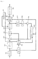
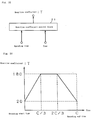
Test Model 3 of ISO-IEC/JTC/SC29/WG11 No. 328. Fig. 1 is a block diagram of a typical MPEG2 video encoding apparatus. This MPEG2 video encoding apparatus comprises aframe converter 101 for shuffling input video signals into encoding sequence, ablock converter 102 for converting picture data into encoding units called macro blocks, asubtractor 103 for determining the difference between an input macro block and a predicted value about its image data, a DCT (discrete cosine transform) 104, aquantizer 105, avariable length encoder 106, aninverse quantizer 107, an IDCT (inverse discrete cosine transform) 108, amotion compensation block 109, a mode discriminator 110, amotion detector 111, aquantizer control block 112, anencoder buffer 113, and anadder 114. - Prior to explanation of operation of thus constituted MPEG2 video encoding apparatus, the data structure of image for encoding is described by referring to Fig. 2.
- Each picture of image to be encoded is divided into macro blocks and encoded. The picture is an image of frame or field unit, and unless otherwise noted, in the following description, the frame is called a picture. This macro block is a data area of 16 × 16 pixels, and the luminance and color difference signals are respectively encoded in a block of 8 × 8 each.
- One data unit called a slice is composed of plural macro blocks, and one picture is composed of plural slices. The picture consists of I picture for encoding within the picture, P picture for predicting from past picture in time, and B picture for predicting from both past and future pictures in time. The picture configuration in Fig. 2 is a typical example, in which a P picture, three pictures ahead, is predicted by using a first I picture, and B pictures existing between them are predicted on both sides. Therefore, when encoding, it is necessary to encode the I picture in the first place, and P picture, then B pictures, which requires to convert the arrangement of images in the original time direction.
- Furthermore, by plural pictures starting from I picture, a group of pictures (GOP) is composed, and one video sequence is composed of an arbitrary number of GOPs. Summing them up, the macro block is defined as an image segment, and the slice, picture, and GOP composed of plural macro blocks may be defined as image segment groups. Supposing the GOP to be an image segment group, for example, the picture which is a smaller image segment group may be defined as a sub-set of GOP or image segment group.
- On the basis of such data structure, the operation of the MPEG2 video encoding apparatus in Fig. 1 is described below.
- An input signal is fed into the
frame converter 101, and the sequence of pictures of input image is converted. The output of theframe converter 101 is supplied into theblock converter 102, and theblock converter 102 divides the entered image into macro blocks of 16 × 16 pixels each, and supplies to thesubtractor 103. In thesubtractor 103, the predicted value obtained from themotion compensation block 109 is subtracted from the signal supplied from theblock converter 102, and a predicted error is determined. The predicted error is transformed in theDCT 104 into each block of 8 × 8, and each transformed coefficient is quantized in thequantizer 105, and quantized data is created. The quantized data is encoded by variable length in thevariable length encoder 106, and compressed encoded data is created. The compressed encoded data is, in order to be transmitted at a desired transmission rate, one stored in theencoder buffer 113, and is issued. - On the other hand, the data quantized in the
quantizer 105 is reproduced in theinverse quantizer 107 and IDCT 108 in order to produce a predicted image. The reproduced image data is put into themotion compensation block 109, and a predicted value is calculated and supplied into thesubtractor 103. Themotion detector 111 calculates the motion vector in every macro block, and the motion vector is put into themotion compensation block 109, and is also supplied into thevariable length encoder 106. Thequantizer control block 112 compares the number of generated bits in the bit stream produced from thevariable length encoder 106 and the target number of generated bits converted from the target bit rate, and controls the quantizing width of thequantizer 105 so that encoding may be finally completed at the target number of bits. - Processing in the
quantizer control block 112 is described below. First, suppose the target number of bits per GOP converted from the target bit rate to be G, the number of bits left over in this GOP in the process of encoding to be R the number of generated bits of the image of I, P, and B pictures encoded immediately before to be respectively SI, SP, SB, and the average of quantizing parameters at this time to be respectively QI, QP, QB. At this time, the difficulty in encoding of each picture XI, XP, XB is respectively defined as


- The method of controlling the quantizing parameters from the target number of generated bits of each picture is described below. First, virtual buffers are assumed for I, P and B pictures, and supposing the target number of generated bits in each macro block to be constant when encoding an i-th macro block, the data remainders of the virtual buffers dIi, dPi, dBi are expressed as follows.

- Using the buffer remainder calculated in the above formulas, the quantizing parameter Qi in the i-th macro block is obtained as follows.


- Summing up the operation, regarding a target bit rate, the target number of generated bits is set in picture unit, and the number of generated bits is limited to the target number of bits in the GOP unit in which the picture is included. In each macro block, depending on the error between the actual number of generated bits and the target number of bits assumed that the number of generated bits to be constant, the quantizing parameter is controlled. As a result, the image is encoded so that the code generation amount may be close to the target number of generated bits of each picture.
- In such encoding method, however, the number of generated bits is set in the picture unit, and the quantizing parameter is controlled so that the number of generated bits may coincide with the target number of generated bits in the GOP unit in which the picture is included, and therefore when the picture changes suddenly and the number of bits required for encoding increases, it is controlled to increase the quantizing width so as to suppress to the target number bits. As a result, the picture quality may deteriorate.
- Or, if the actual number of generated bits increases extremely from the target number of generated bits in a certain GOP, it is controlled so that the target number of generated bits in next GOP may absorb this error, and when the picture quality in that GOP may deteriorate.
- Yet, when relatively flat images are concentrated in a first half of a certain picture and complicated images are concentrated in a second half, it is ideal to assign more bits in the second half. In the above method, however, the target number of bits is uniformly assigned in each macro bit, and the quantizing parameter is set depending on the error from the number of bits required actually in each macro block, and hence there was a possibility of assignment of more bits in the first half and occurrence of more bits than expected in the second half. To the contrary, if complicated images are concentrated in the first half, the number of bits generated in the first half is limited, and bits are not assigned ideally.
- To overcome such problems, it may be considered to encode once all images, determine the ideal bit distribution in all images, and encode again, but it is difficult to encode in real time.
- It is hence an object of the invention to provide a moving picture encoding apparatus and method capable of distributing bits appropriately depending on the difficulty in encoding moving pictures.
- It is other object of the invention to provide a moving picture encoding apparatus and method for setting an appropriate quantizing width by distributing bits appropriately without once encoding all images.
- It is a different object of the invention to provide a moving picture encoding apparatus and method for determining target bits to be generated so as to absorb the error between the target number of generated bits to be generated in one image segment composed of plural pictures such as GOP, and the number of actually generated bits, gradually over plural image segment groups.
- It is a further object of the invention to provide a moving picture encoding apparatus and method for controlling the target quantity of generated bits so that the target quantity of generated bits may not change abruptly in adjacent picture segment groups.
- It is a further different object of the invention to provide a moving picture encoding apparatus and method capable of controlling an optimum quantizing width on the basis of the target number of generated bits to be generated in one image segment group.
- According to the invention, the error between the target number of generated bits to be generated in one image segment and the number of actually generated bits is distributed to the target quantity of generated bits to be generated in each one of other plural image segment groups.
- Also according to the invention, if the number of bits generated at the time of encoding of the sub-set of a certain image segment is out of a specified range, the quantizing parameter for encoding the sub-set of a subsequent image segment is controlled to a value different from the preceding quantizing parameters.
- Fig. 1 is a block diagram of an example of a general MPEG2 encoder.
- Fig. 2 is a schematic diagram showing a picture configuration of MPEG2.
- Fig. 3 is a block diagram showing a constitution of a first embodiment of the invention.
- Fig. 4 is a block diagram showing a constitution of an example of a
complexity detector 4 in Fig. 3. - Fig. 5 is a block diagram showing a constitution of an example of a
quantizer control block 6 in Fig. 3. - Fig. 6 is flowchart showing a calculating method of quantizing parameter by a
control unit 16 in Fig. 5. - Fig. 7 is a graph schematically showing a calculating method of quantizing parameter.
- Fig. 8 is a flowchart explaining a calculating method of quantizing parameter in each picture.
- Fig. 9 is a timing chart schematically explaining increase or decrease in the number of bits generated per GOP at advanced complexity of encoding.
- Fig. 10 is a timing chart schematically explaining changes in the number of bits generated per GOP and picture quality in the case of an extended duration of information of advanced complexity of encoding.
- Fig. 11 is a timing chart comparing the target number of bits generated per macro block and the number of generated bits between a conventional method and the method of the first embodiment of the invention.
- Fig. 12 is a block diagram showing other example of determining complexity of encoding.
- Fig. 13 is a block diagram showing a constitution of a second embodiment of the invention.
- Fig. 14 is a block diagram showing a constitution of an example of a quantizer control block 22 in Fig. 13.
- Fig. 15 is a flowchart explaining a calculating method of quantizing parameter by a control unit 223 in Fig. 14.
- Fig. 16 and Fig. 17 are flowcharts explaining further calculating methods of quantizing parameter by the control unit 223.
- Fig. 18 is a timing chart explaining the correlation of the complexity of encoding of picture, number of generated bits, and picture quality.
- Fig. 19 is a block diagram showing a constitution of an example of controlling a reaction coefficient T.
- Fig. 20 is a timing chart showing an example of reaction coefficient T.
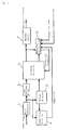
- Fig. 3 is a block diagram showing a constitution of an example of a moving picture encoding apparatus of the invention, in which the moving picture encoding apparatus of the invention comprises a
frame converter 1, aframe delaying block 2, anencoding processor 3, acomplexity detector 4 for analyzing the input image and calculating the difficulty in encoding, amotion detector 5, aquantizer control block 6, and anencoder buffer 7. Theencoding processor 3 comprehensively includes the actions of theblock converter 102,subtractor 103,DCT 104,quantizer 105,variable length encoder 106,inverse quantizer 107,IDCT 108,motion compensation block 109,mode discriminator 110, andadder 114 of the typical moving picture encoding apparatus shown in Fig. 1. - Input images are shuffled in the input image encoding sequence in the
frame converter 1. Themotion detector 5 calculates the motion vector for each macro block by comparison with each reference picture, as for P picture and B picture. This motion vector is sent into theencoding processor 3, and is used for creation of predicted image with motion compensation. The motion vector is also supplied to thecomplexity detector 4. - Fig. 4 is a block diagram showing a constitution of an example of the
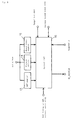
complexity detector 4. Thecomplexity detector 4 comprises a predictederror image generator 8, aDCT 9, a variable length encoder 11, and a generatedbit counter 12. The image data from theframe converter 1 is supplied into the predictederror image generator 8 together with motion vector signal. In the predictederror image generator 8, if the input image is an I picture, the image is held as it is, and in the case of a P picture, by the motion vector from themotion detector 5, a predicted error image is created by the difference between the predicted image and the input image. Similarly, in the case of a B picture, a predicted error image is created from predicted results on both sides. - In the
DCT 9, successively, the image is transformed in each block, and is quantized in thequantizer 10, and is encoded in the variable length encoder 11. At this time, thequantizer 10 quantizes always with a constant quantizing parameter. The value of the quantizing parameter (q_scale) may be an arbitrary value, and herein quantizing is processed at q_scale=10 for the sake of convenience. The generatedbit counter 12 detects the number of bits of the encoded data in every macro block, and multiplies by a fixed value of q_scale, and calculates complexity showing the difficulty in encoding in each macro block. The generated bit counter 12 sums up the complexity values of each macro block, and supplies the complexity per picture to the quantizer control block. - On the other hand, the input image is delayed by the portion of one picture in the
frame delaying block 2, and is supplied into theencoding processor 3. Theencoding processor 3 encodes same as the moving picture encoding apparatus shown in Fig. 1, according to the encoding parameter supplied from thequantizer control block 6, and generates a bit stream conforming to the MPEG standard. - The
quantizer control block 6 determines the quantizing parameter q_scale on the basis of the number of generated bits of the bit stream from theencoding processor 3, the complexity from thecomplexity detector 4, and the target bit rate, and further determines the quantizing width when encoding in theencoding processor 3. - Fig. 5 shows a block diagram of a constitution of an example of the
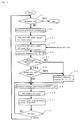
quantizer control block 6. Thequantizer control block 6 comprises a generated bit counter 13 for counting the number of bits generated in the bit stream for the portion of one GOP generated by theencoding processor 3, a generated bit counter 14 for counting the number of generated bits for the portion of one picture, a generated bit counter 15 for counting the number of generated bits for the portion of one macro block, and acontrol unit 16. Thecontrol unit 16 generates the quantizing parameter q_scale in every macro block timing on the basis of the number of generated bits obtained from the generated bit counters 13, 14, 15, the target bit rate, maximum transmission rate Dec_R when sending a bit stream to the video decoder, and the complexity obtained from thecomplexity detector 4. - Fig. 6 is a flowchart showing an example of algorithm for calculating q_scale performed in the
control unit 16. - First, at step S1, it is judged if a sequence end code is detected or not, and if not detected, the process goes to step S2. At step S2, when encoding a j-th GOP, the number of generated bits GOP_Bj-1 in the immediately preceding GOP is read out from the generated
bit counter 13. It is, however, 0 in the first GOP. Next, at step S3, the error DIF_Gj between the number of generated bits immediately before encoding the j-th GOP and the target number of bits G calculated by supposing that all GOPs generate the same number of bits is calculated in the following formula.
- At next step S4, when encoding the j-th GOP, the target number of generated bits R(j) is calculated in the following formula.

- Once the target number of generated bits per GOP is determined, then, at step S5, temporary values of target number of generated bits per picture TTI, TTP, TTB are calculated in the following formulas.

complexity detector 4, or the fixed value, for example, XI:XP:XB = 160:60:42. Besides, NP, NB are number of P pictures and B pictures in the GOP. Values of Kp, Kb are constants for correction determined from the quantizing matrix, and herein Kp=1.0, Kb=1.4. - In I, P, B pictures, consequently at step S6, CI, CP, CB are set as the reference complexity of reference difficulty in encoding. Step S6, however, is skipped when the reference complexity is already read in and the target bit rate is not changed as a result of judging routine at step S8 and step S9, and the immediately preceding value is directly the set value. Setting the quantizing parameter q_scale at 10, the reference complexity is set at such a value that the number of bits generated when encoded by this quantizing parameter may be equal to the temporary values TTI, TTP, TTB of the target number of generated bits.
- At next step S9, the average quantizing parameter q_pic is set when encoding so that the reference complexities CI, CP, CB may be the number of generated bits of TTI, TTP or TTB in the picture at that point.
- At step S10, the target numbers of generated bits TI, TP, TB of the picture to be encoded are set. Using the complexity supplied from the
complexity detector 4, the number of bits necessary when encoded at the set q_pic is set as TI, TP, TB. - At step S11, the quantizing parameter in the picture is controlled, and this step is further described below.
- Finally at step S12, it is judged if the GOP end code has been detected or not, and if GOP end code is not detected, process from step S9 is repeated, and if GOP end code is detected, the process returns to step S1.
- The process from determination of temporary target number of generated bits TTI, TTP, TTB (step S5) till determination of target number of generated bits TI, TP, TB (step S10) is described below while referring to the graph in Fig. 7.
- In the graph in Fig. 7, the axis of abscissas denotes the complexity, indicating the difficulty in encoding, and the axis of ordinates represents the number of generated bits. When quantized at q_scale=10, the relation between complexity and number of generated bits is expressed by line a. In the first picture, the intersecting point of the temporary target number of generated bits TT0 per picture and line (a) is the reference complexity. The complexity in the next picture is detected by the
complexity detector 4, and supposing the value to be CC0, the target number of generated bits of that picture is T0 as shown in the diagram. The target number of generated bits per picture is determined depending on the complexity obtained from thecomplexity detector 4, and the same operation is repeated until one GOP is completed. - When processing for one GOP is over, the target number of generated bits R(j) assigned to next GOP is determined by formula (9). Consequently, depending on the target number of generated bits for newly assigned GOP, the temporary target number of generated bits of each picture obtained in formulas (10) to (12) varies. At this time, supposing the temporary target number of generated bits to be TT1, a line (b) passing through the intersection of TT1 and reference complexity is newly drawn. When the complexity obtained from the
complexity detector 4 is CC1, the target number of bits T1 at the intersection of line (b) and CC1 is the target number of bits of the picture at this moment. - Incidentally, the line in Fig. 7 has its upper limit and lower limit values. The upper limit value is determined in the following formula, supposing the data remainder in the reproduction side decoder buffer to be VBV_fullness, the initial value to be 1.8M bits as the buffer capacity of standard decoder, and the picture rate to be Pic_R:

- On the other hand, the lower limit value of the line of q_scale is determined empirically so that the bit rate may not be less than 2 Mbps.
- The detail of the control of q_scale in every macro block by quantizing parameter control in the picture at step S11 in the flowchart in Fig. 6 is described below.
- Fig. 8 is a flowchart for explaining the quantizing parameter control process in the picture. Herein, the value of quantizing parameter q_scale in an i-th macro block is MQUANTi, the virtual buffer for rate control is defined, and the data remainder before encoding of the i-th macro block is supposed to be di. The initial value of di is determined in


- First at step S111, the complexity of the entire picture, C_pic, is read. At step S112, judging if first macro block or not, when judged to be first macro block, at step S113, MQUANTi, the value of quantizing parameter q_scale of the first macro block is set at q_pic,

- If not judged to be first macro block as a result at step S112, the data remainder di before encoding this macro block is determined in the following method.
- First, at step S114, the number of bits generated in the immediately preceding macro block B_mb(i-1) is read from the generated
bit counter 15. At next step S115, C_mb(i-1) is determined as the complexity of the immediately preceding macro block from thecomplexity detector 4, and the number of bits T_mb (i-1) predicted to be generated in the immediately preceding macro block is determined in the following formula.

encoding processor 3.
- Summing them up, by the reference complexity in every picture calculated from the target bit rate, the temporary target numbers of generated bits TTI, TTP, TTB are determined, the target number of generated bits is corrected from the temporary value in the correlation between the reference complexity and the complexity in the picture at that point obtained from the
complexity detector 4, and therefore the number of bits may be assigned accordingly if there is a scene change or a region of violent action in the picture, or when the complexity increases abruptly. - Besides, the error from the number of generated bit controlled depending on the complexity in every picture and the target generated bits is adjusted over plural GOPs, and the effect of bit distribution in a GOP immediately after a certain GOP is lessened.
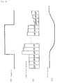
- For example, Fig. 9 schematically shows the changes of number of generated bits in GOP unit in the case of momentary increase of complexity in the image of a constant complexity. In Fig. 9(a), for a specific period, an image of a specific complexity continues, and the complexity suddenly increases at a certain point, and then an image of a specific complexity continues again. In the conventional assigning method of number of generated due to sudden change in complexity, extremely few bits are assigned. In this embodiment, by contrast, it is understood that changes in the target number of generated bits in the GOP right after are small. That is, if the number of generated bits in a certain GOP is doubled, only 1/T of the error from the target number of generated bits of that GOP has an effect on the target generated bits of the next GOP. Supposing T=20, if one GOP is supposed to compose an image for 0.5 second, almost all bit rates are recovered to the target bit rate in 10 seconds.
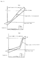
- Fig. 10 schematically shows the mode of deterioration of picture quality in terms of the number of bits generated in every GOP and the quantizing width when an image of constant complexity continues, and is succeeded by an image of relatively complicated and constant complexity, then succeeded by an image of the initial complexity. That is, when the complexity increases, the number of generated bits of GOP increases in order to maintain the picture quality, but it is corrected to the number of generated bits for maintaining the bit rate exponentially. At this time, the picture quality will not deteriorate suddenly, but it declines continuously for a period of several seconds. When returning to the initial complexity, the number of bits generated in the immediately succeeding GOP decreases, but it also returns to the optimum number of generated bits exponentially. At this time, the picture quality can be continuously recovered for a period of several seconds from the picture quality difficult in encoding.
- Incidentally, it is also possible to control the picture quality continuously if the target bit rate is changed on the way of encoding. That is, if the target bit rate is decreased, the reference set value of complexity decreases also at the same rate. Therefore, if encoded at a target rate, the temporary target number of generated bits of next picture also decreases nearly in proportion to the target number of generated bits, and therefore the average quantizing parameter of the picture is nearly the same as in the case when the target number of generated bits is directly maintained, and it changes exponentially in the subsequent pictures.
- Moreover, according to the embodiment, since the quantizing width per macro block is also controlled depending on the complexity of each macro block in the picture, and therefore the error from the target bit rate is small, and the picture can be encoded in an appropriate bit distribution.
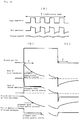
- Fig. 11 schematically compares control of quantizing parameter by the conventional method and control of quantizing parameter in the embodiment. Fig. 11 (a) shows the actual number of generated bits and target number of generated bits in the conventional method, and Fig. 11 (b) shows the actual number of generated bits and target number of generated bits in the method of the invention.
- When the target number of generated bits T in a certain picture is set, according to the conventional method, assuming the number of bits generated in each macro block to be uniform, the difference from the actual number of generated bits was defined as the data remainder of the virtual buffer, and the quantizing parameter was controlled accordingly. Therefore, in the image having the peak of complexity in the latter half of the image, the actual bit generation amount is small in the first half of the image, and hence the quantizing parameter decreases, so as to be encoded at higher picture quality than the initially demanded picture quality. In the latter half of the image, however, the bit generation amount increases, and finally the number of bits may be larger than the target number of generated bits, or the quantizing parameter may increase suddenly due to increase of the buffer remainder, which may lead to deterioration of picture quality.
- On the other hand, according to the embodiment, since the target number of generated bits in each macro block is set as in formula (16) depending on the complexity, the bit distribution is close to the complexity distribution in the picture, so that both picture quality and number of generated bits are close to the target.
- In the embodiment, the difference between the target bit rate and the number of generated bits is determined in the GOP unit, and the target number of generated bits is corrected, but it may be also done in the picture unit or other unit. That is, the macro block, the minimum value of the processing unit of encoding in this embodiment, may be defined as an image segment, and a set of image segments, such as slice, picture and GOP may be defined as an image segment group, so that the target number of generated bits may be corrected in the unit of an arbitrary image segment group.
- As for setting of reference value of complexity of encoding, not limited to setting by using q_scale=10, other quantizing parameter may be used, or if the target bit rate is not changed, a fixed value may be set from the beginning.
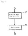
- Instead of the complexity used for determining the parameters, other index may be used. For example, determining the square sum of average and error equivalent to activity of each picture, it may be replaced by the complexity in each formula. Fig. 12 is a block diagram for composing this embodiment by using the activity. A predicted
error image generator 17, same as in the constitution shown in Fig. 4, generates the I picture as it is, and P and B pictures from the predicted errors. Anoperation block 18 determines the square error of each macro block from the predicted error image from the predictederror image generator 17. The total is used as the substitute for the complexity of the entire picture. - In this embodiment, the
quantizer control block 6 is explained as a structure independent of theencoding processor 3, but when the encoding apparatus itself is composed of DSP (digital signal processor), it may be used commonly with a block for other processing. - A second embodiment of the invention is described below. Fig. 13 is a block diagram showing a constitution of the second embodiment of the invention, in which an input signal is supplied into an
encoding processor 20. The encodingprocessor 20 encodes each macro block into a signal conforming to MEPG2 according to the value of quantizing width q_scale indicted by a quantizer control block 22, and supplies the encoded signal into an encoder buffer 21 and the quantizer control block 22. The encodingprocessor 20 also supplies the received GOP end timing signal and picture end timing signal to the quantizer control block 22. The quantizer control block 22 determines the quantizing width q_scale from the target bit rate, reaction coefficient T, and encoded data and timing signal supplied from the encodingprocessor 20, and supplies the quantizing width q_scale to theencoding processing 20, and controls the number of generated bits and picture quality. - Fig. 14 is a block diagram showing a constitution of an example of the quantizer control block 22 in Fig. 13, and the quantizer control block 22 includes a GOP counter 221 for counting the number of bits generated in every GOP, a picture counter 222 for counting the number of bits generated in every picture, and a control unit 223 for calculating q_scale. To the GOP counter 221 and picture counter 222, encoded data is supplied from the encoding
processor 20, and the number of generated bits is counted. The control unit 223 detects the number of bits generated in every GOP or picture whenever receiving the GOP end timing signal and picture end timing signal, and calculates q_scale from the target bit rate (R) and reaction coefficient (T). - Fig. 15 is a flowchart for explaining an example of calculating method of q_scale by the quantizer control block 22.
- First, as initial processing, at step S20, the error DIF_Gi between the target number of generated bits per GOP calculated from the target bit rate R (bps) and the present number of generated bits, reference value q_st of q_scale, and virtual buffer occupation capacity VBV_Buffer-fullness of the decoder are set. The minimum number of generated bits per picture D0 is set at 1,000,000 bits/picture rate, and the maximum number of generated bits D1 at 8,000,000 bits/picture rate. The set value of D0 is determined from the empirical rule that the picture quality drops significantly when the encoding rate becomes lower than 1 Mbps. On the other hand, the maximum value D1 may be matched with the data transmission rate capable of transmitting to the decoder by the reproducing apparatus, or may be set at an arbitrary value around, or below it.
- At next step S21, q_scale of the picture to be encoded is calculated and issued according to the following formula.

- Also as clear from the formula, all quantizing parameters for encoding a certain picture can be obtained from the past ones. Q_scale obtained at step S21 is supplied to the
encoding processor 20 at step S22. - At step S23, picture end timing is detected. When picture end timing is detected, at step S24, the number of bits generated in picture PIC_CNT is detected. On the basis of the result of detection, at step S25, the occupation capacity of virtual buffer is determined in the following formula.


- At step S26, it is judged if VBV_Buffer_fullness is below the lower limit D2 of the buffer occupation capacity of the reproducing side decoder or not, and if below the lower limit D2, a picture skip processing signal is issued at step S27 to avoid underflow.
- At step S27, PIC_CNT is judged to be below the lower limit D0 or not, and when PIC_CNT is smaller than the lower limit D0, at step S28, q_scale is decreased so that the number of bits may not be smaller than the lower limit in the subsequent pictures. Fig. 16 is a flowchart for explaining the operation for setting q_scale to be used in next picture when the number of bits generated per picture is below the lower limit D0. Usually, q_scale is decreased by one each, but if PIC_CNT is significantly smaller than the lower limit, for example, if less than 1/2 of the lower limit D0, the decreasing width is varied depending on q_scale at that time. Generally, in the encoding process in a certain picture, the product of the q-scale value and number of generated bits, that is, complexity is said to be almost constant. That is, when q_scale is half, the number of generated bits is doubled. When a relatively large value is assigned for q_scale, to control the number of generated bits by varying the value, it is understood that the changing amount must be larger as compared with the case of a smaller q_scale value.
- Among I, P, B pictures, it is the B picture that has a strong tendency of the number of generated bits being smaller than the lower limit D0, and when the quantizing width is controlled from the number of generated bits of the B picture, the increase or decrease in the number of generated bits in other pictures is significant. Accordingly, by setting q_scale to such an extent that the error from the lower limit D0 may be recovered to about half, the changing amount is set to a degree so that the number of generated bits may reach the lower limits in several pictures. In the flowchart in Fig. 16, first at step S281, it is judged if PIC_CNT is smaller than ½ of the lower limit D0, and if smaller, q_scale is subtracted by the value corresponding to the preceding value. That is, at step S282, if the preceding q_scale exceeds 9, 3 is subtracted at step S283. At step S284, if the preceding q_scale is judged to be 6 or more to 9 or less, 2 is subtracted at step S285. In the case of a further smaller q_scale, it is judged if q_scale is larger than 1 or not at step S286, and if the result is TRUE, 1 is subtracted from the preceding q_scale at step S287.
- On the other hand, if PIC_CNT is not smaller than 1/2 of the lower limit D0, at step S289, 1 is subtracted from the preceding q_scale, but if q_scale is judged to be 1 or less at step S288, subtraction is not processed.
- Thus, if the number of bits generated in picture PIC_CNT as the sub-set of image segment is smaller than the specified lower limit, the quantizing parameter is subtracted depending on the difference from the lower limit.
- Back to Fig. 15, it is judged whether PIC_CNT is over the upper limit D1 or not at step S29, and if PIC_CNT exceeds the upper limit D1, q_scale is increased at step S30 to control the generated code amount so as not to exceed the upper limit. The process of increasing q_scale is shown in Fig. 17. That is, at step S301, if it is judged that PIC_CNT is more than twice of D1, at step S302, it is judged if the preceding q_scale is over 9 or not, and if the result is TRUE, at step S303, 4 is added to the preceeding q_scale. Or, by the processing of S302, if it is judged that q_scale is smaller than 9, at step S304, 2 is added to the preceding q_scale. On the other hand, if PIC_CNT is judged to be smaller than twice of the upper limit D1 as a result of judgement at step S301, it is judged at step S305 whether the preceding q_scale is smaller than 31 or not. If the preceding q_scale is smaller than 31, at step S306, 1 is added to the preceding q_scale, and otherwise the same preceding value is set in q_scale value. Thus, the changing amount varies depending on the value of the preceding q_scale because a large changing amount is needed if the quantizing width is large. Besides, in the case of I picture or scene change, the number of generated bits may temporarily exceeds the upper limit, and hence the value of q_scale is changed so that the number of generated bits may settle within the upper limit in several pictures.
- In this way, when the number of bits generated in picture PIC_CNT as the sub-set of image segment is larger than the specified upper limit, the quantizing parameter is increased depending on the difference from the specified upper limit.
- Again back to Fig. 15, at step S31, whether GOP end timing or not is judged, and if not GOP end, the control job of q_scale for controlling the number of generated bits between lower limit and upper limit is repeated in every picture. When receiving GOP end timing, the number of bits generated in GOP GOP_CNT is detected at step S32, and the error DIF_Gi from the present number of generated bits is calculated in the following formula at step S33.

- What is characteristic of the processing mentioned so far is that, as compared with the first embodiment in which the complexity of the picture to be encoded must be detected from the
complexity detector 4, the change of q_scale, in the second embodiment, is determined by comparison between the number of bits generated in the sub-set of the image segment encoded immediately before with the upper limit or lower limit, so that the moving picture encoding apparatus more suited to real time processing may be specified. - The picture skip signal issued by the control unit 223 in Fig. 14 is supplied to the
encoding processor 20 in order to prevent underflow of virtual buffer. The encodingprocessor 20 receiving the picture skip signal skips encoding for the portion of one picture. - Fig. 18 is a graph schematically showing changes in the number of bits generated in relation to the complexity of input image and the picture quality. Fig. 18 (a) shows the changes of complexity occurring in a sufficiently short time for the reaction coefficient T, and changes of the number of generated bits and picture quality according to the first embodiment. That is, if the complexity of image changes in a relatively short time interval, the number of generated bits is assigned depending on the complexity of encoding of image, and it is understood that the picture quality is kept almost constant.
- On the other hand, as shown in Fig. 18 (b), when encoding of input image is extremely difficult and such signal lasting relatively for a long time is supplied, according to the assigning method of the target number of bits of the first embodiment, the number of bits is generated depending on the complexity of input image, and later the bit generation amount decreases exponentially with the reaction coefficient T as parameter. Accordingly, the number of bits becomes lower than relatively soon than the number of bits necessary for maintaining a sufficient picture quality and the interval to maintain a sufficient picture quality is short. By the assigning method of target number of bits of the second embodiment, the image interval requiring bit generation over the maximum bit quantity is encoded quickly by a smaller number of bits than the maximum bit quantity, and a sufficient picture quality is maintained for a long period.
- Fig. 18 (c) is a graph schematically expressing the relation between the number of generated bits and the picture quality in the case of a long duration of image of high complexity followed by a long duration of image of low complexity. According to the first embodiment of the invention, right after changing over to an image of low complexity, the number of generated bits decreases extremely, and then the number of generated bits increases exponentially by the reaction coefficient T. For recovery of picture quality, however, the period determined by the reaction coefficient T is required. In the second embodiment of the invention, by contrast, the number of generated bits reaches the lower limit quickly, and a fair picture quality is maintained.
- In the second embodiment, too, the error between the target bit rate and big generation is calculated in the GOP unit, but instead of the GOP unit, the bit generation error may be also calculated in the unit of several pictures.
- The changing amount of q_scale in every picture can be also set arbitrarily so that the number of bits generated per picture may be controlled between the upper limit and lower limit.
- The reaction coefficient T is explained as a fixed value in the first and second embodiments, but it can be also changed arbitrarily. That is, the reaction coefficient is set so as to absorb the error occurring in a certain GOP between the number of generated bits and the target number of generated bits over T GOPs to follow, and therefore a preferred reaction coefficient T should be set depending on the actual system. For example, it is preferred to determine the reaction coefficient T depending on the total number of GOPs to be encoded, or the reaction coefficient may be changed nonlinearly depending on the time in the case of a limited reproduction time such as optical disk.
- Fig. 19 is a block diagram showing a constitution of an example of variable control of reaction coefficient T depending on the time, in which a reaction coefficient control block 23 issues a reaction coefficient T by receiving the encoding time of the image to be encoded, and the time on the basis of start of encoding of the presently encoded portion. Fig. 20 is a graph showing the input and output characteristics of the reaction coefficient control block 23. In this embodiment, as clear from formula (19), when the bit generation error becomes T times the bit rate, the quantizing width is infinite in numerical formula, and hence the upper limit of bit generation is guaranteed. That is, the reaction coefficient T is a parameter for determining the upper limit of the error allowable against the target rate in the actual system. On the other hand, the larger the reaction coefficient T, it is applicable to the longer interval such as scene change, and a desired operation is realized when a larger reaction coefficient is given. For example, the reaction coefficient T is set at a large value in the first half of encoding, and is decreased gradually at the end of encoding so as to be a smaller value. In this way, the final error of number of generated bits is guaranteed relatively small in the finally set value of T, and in the intermediate portion of encoding, the reaction coefficient T is set large, and it is applicable to a scene of a relatively long time. Fig. 20 is a graph showing the changes of reaction coefficient T. Herein, supposing the encoding completion time to be C, the intermediate 1/3 period is T=180, and in the first 1/3, T is gradually changed from T=20 to T=180, and in the final 1/3, T is gradually changed from T=180 to T=20. In this way, since the reaction coefficient T is large in the intermediate portion of encoding, the error in the number of generated bits can be adjusted in a short time in the first and final portions. This is particularly effective when the beginning and end of the picture to be coded are easily encoded scenes such as the title and ending of a movie, and in the body of the movie, since the reaction coefficient T can be set large, the video source of excellent picture quality can be presented.
- In Fig. 20, incidentally, the decrease starting time of reaction coefficient T is the time of 2/3 of the encoding time, but when scenes of relatively low complexity in encoding are expected, such as the title and the cast at the ending of a moving, the reaction coefficient decrease time may be set immediately before end of encoding, so that the reaction coefficient can bet set large in almost all range of the movie, so that a high picture quality is realized.
- The value of T is set between 20 and 180, but it is not limited. For example, if T is about 5, it is effective to maintain the picture quality sufficiently in the scene change in which the picture quality was lowered in conventional encoding of fixed rate, and encoding of high picture quality is possible by increasing the reaction coefficient as much as possible as the error of number of generated bits may be allowed.
- Furthermore, in the second embodiment, the changing amount of the q_scale value when the bit generation per picture has exceeded the upper limit or lower limit is controlled to be within the range of upper limit or lower limit in several frames later, assuming the images of same complexity continue, but it may be also determined by calculation so as to set q_scale also to 1/2 when, for example, the lower limit of the number of generated bits becomes 1/2, and the changing amount is arbitrary as far as the quantizing width is controlled so as to settle the number of bits generated per picture between the upper limit and lower limit.
- Thus according to the invention, the target bits generated and the quantizing parameter are set so as to absorb the error between the target number of generated bits in image segment group such as GOP unit and the number of generated bits gradually to the target number of bits assigned in the plural succeeding image segment groups, and therefore it is possible to avoid sudden picture quality changes if the images are changed abruptly.
- Also according to the invention, if the number of generated bits in the sub-set of image segment such as the preceding picture is outside the range specified by the upper limit and lower limit, the quantizing parameter in the sub-set in the next image segment is changed, and therefore it is possible to control the target number of bits generated and the quantizing parameter without preliminarily detecting the number of generated bits necessary for encoding of the image unit.
- Various changes and modifications of the foregoing embodiments are possible so far as not departing from the scope and true spirit of the invention.
Claims (40)
- A moving picture encoding apparatus for compressing and encoding a picture depending on a target bit rate, comprising a control unit for adjusting the target number of bits depending on the result of dividing the error between the target number of bits corresponding to the target bit rate and the number of generated bits required for encoding image segment groups just before by a number of 2 or more, and controlling the quantizing parameter for encoding the image segment groups depending on the adjusted target bits generated.
- A moving picture encoding apparatus of claim 1, further comprising an encoding processor for encoding the input image signal into an image signal conforming to MPEG2, according to the quantizing parameter.
- A moving picture encoding apparatus of claim 1, further comprising complexity detecting means for generating an index showing difficulty of encoding depending on the number of bits generated required for encoding by encoding an arbitrary segment group, and quantizing width calculating means for calculating the quantizing width depending on the target number of generated bits, by setting the reference value of complexity showing the difficulty of encoding of each image segment group, determining the target number of generated bits when encoding the present image segment group calculated from the target bit rate as the reference number of generated bits for encoding the image segment group of the reference value of the complexity, and setting the target number of generated bits when encoding the present image segment group so that the difference between the target number of generated bits of encoding of the present image segment group and the reference number of generated bits may correlate with the difference from the reference value of the complexity of the present image segment group detected by the complex detecting means.
- A moving picture encoding apparatus of claim 1, wherein the image segment block is a macro block, and the image segment group is at least one of slice, picture, and GOP.
- A moving picture encoding apparatus of claim 4, wherein the GOP includes an encoded picture in a picture (I picture), a forward direction predicted encoded picture (P picture), and both direction predicted encoded picture (B picture).
- A moving picture encoding apparatus of claim 4, wherein the control unit assigns the target number of generated bits in each macro block, from the complexity in each macro block for composing the picture, the complexity over the entire picture, and the target number of bits of entire picture.
- A moving picture encoding apparatus for controlling a quantizing parameter when compressing a picture, corresponding to a target bit rate, comprising a control unit for controlling the quantizing parameter depending on the result of dividing the error between the target hit rate and the number of hits generated up to the present image segment group by a number of 2 or more.
- A moving picture encoding apparatus for controlling a quantizing parameter when compressing a picture, corresponding to a target bit rate, characterized by controlling the quantizing parameter depending on the result of dividing the error between the target bit rate and the number of bits generated up to the present image segment group by a number of 2 or more, and varying the quantizing parameter when encoding the sub-set of the succeeding image segment, if the number of generated bits required for encoding in every sub-set of the image segment dividing the image segment group into plural sections is over a specified upper limit or under a specified lower limit.
- A moving picture encoding apparatus of claim 8, wherein the control unit increases the quantizing parameter if the number of generated bits required for encoding the sub-set of the immediately preceding image segment is over the specified upper limit.
- A moving picture encoding apparatus of claim 8, wherein the control unit decreases the quantizing parameter if the number of generated bits required for encoding the sub-set of the immediately preceding image segment is under the specified upper limit.
- A moving picture encoding apparatus of claim 9, wherein the control unit increases the changing amount corresponding to the quantizing parameter used for encoding the immediately preceding sub-set if the number of generated bits required for encoding the sub-set of the immediately preceding image segment is over the specified upper limit.
- A moving picture encoding apparatus of claim 10, wherein the control unit decreases the changing amount corresponding to the quantizing parameter used for encoding the immediately preceding sub-set if the number of generated bits required for encoding the sub-set of the immediately preceding image segment is under the specified upper limit.
- A moving picture encoding apparatus of claim 7 or 8, further comprising an encoding processor for creating an encoded image conforming to MPEG2 depending on the quantizing parameter.
- A moving picture encoding apparatus of claim 8, wherein the image segment group is a GOP, and the sub-set of image segment is a picture.
- A moving picture encoding apparatus of claim 1 or 7, wherein the number used when dividing the error between the number of bits generated required for encoding the immediately preceding image segment group, and the target number of generated bits depending on the target bit rate is 20 to 180.
- A moving picture encoding apparatus of claim 15, wherein the number used in the division has values of at least two kinds or more.
- A moving picture encoding apparatus of claim 15 or 16, wherein the number used in the division varies depending on the time for encoding.
- A moving picture encoding method for compressing and encoding a picture depending on a target bit rate, comprising a control unit for adjusting the target number of bits depending on the result of dividing the error between the target number of bits corresponding to the target hit rate and the number of generated bits required for encoding image segment groups just before by a number of 2 or more, and controlling the quantizing parameter for encoding the image segment groups depending on the adjusted target bits generated.
- A moving picture encoding method of claim 18 further comprising a step of encoding the input image signal into an image signal conforming to MPEG2, according to the quantizing parameter.
- A moving picture encoding method of claim 18, further comprising the steps of generating an index showing difficulty of encoding by complexity detecting means depending on the number of bits generated required for encoding by encoding an arbitrary segment group, and calculating the quantizing width by quantizing width calculating means depending on the target number of generated bits, by setting the reference value of complexity showing the difficulty of encoding of each image segment group, determining the target number of generated bits when encoding the present image segment group calculated from the target bit rate as the reference number of generated bits for encoding the image segment group of the reference value of the complexity, and setting the target number of generated bits when encoding the present image segment group so that the difference between the target number of generated bits of encoding of the present image segment group and the reference number of generated bits may correlate with the difference from the reference value of the complexity of the present image segment group detected by the complex detecting means.
- A moving picture encoding method of claim 18, wherein the image segment block is a macro block, and the image segment group is at least one of slice, picture, and GOP.
- A moving picture encoding method of claim 21, wherein the GOP includes an encoded picture in a picture (I picture), a forward direction predicted encoded picture (P picture), and both direction predicted encoded picture (B picture).
- A moving picture encoding method of claim 21, characterized by assigning the target number of generated bits in each macro block, from the complexity in each macro block for composing the picture, the complexity over the entire picture, and the target number of bits of entire picture.
- A moving picture encoding method for controlling a quantizing parameter when compressing a picture, corresponding to a target bit rate, characterized by controlling the quantizing parameter depending on the result of dividing the error between the target bit rate and the number of bits generated up to the present image segment group by a number of 2 or more.
- A moving picture encoding method for controlling a quantizing parameter when compressing a picture, corresponding to a target bit rate, characterized by controlling the quantizing parameter depending on the result of dividing the error between the target bit rate and the number of bits generated up to the present image segment group by a number of 2 or more, and varying the quantizing parameter when encoding the sub-set of the succeeding image segment, if the number of generated bits required for encoding in every sub-set of the image segment dividing the image segment group into plural sections is over a specified upper limit or under a specified lower limit.
- A moving picture encoding method of claim 25, characterized by increasing the quantizing parameter if the number of generated bits required for encoding the sub-set of the immediately preceding image segment is over the specified upper limit.
- A moving picture encoding method of claim 25, characterized by decreasing the quantizing parameter if the number of generated bits required for encoding the sub-set of the immediately preceding image segment is under the specified upper limit.
- A moving picture encoding method of claim 26, characterized by increasing the changing amount corresponding to the quantizing parameter used for encoding the immediately preceding sub-set if the number of generated bits required for encoding the sub-set of the immediately preceding image segment is over the specified upper limit.
- A moving picture encoding method of claim 27, characterized by decreasing the changing amount corresponding to the quantizing parameter used for encoding the immediately preceding sub-set if the number of generated hits required for encoding the sub-set of the immediately preceding image segment is under the specified upper limit.
- A moving picture encoding method of claim 24, characterized by creating an encoded image conforming to MPEG2 depending on the quantizing parameter.
- A moving picture encoding method of claim 24, wherein the image segment group is a GOP, and the sub-set of image segment is a picture.
- A moving picture encoding method of claim 18 or 24, wherein the number used in the division is 20 to 180.
- A moving picture encoding method of claim 32, wherein the number used in the division has values of at least two kinds or more.
- A moving picture encoding method of claim 32 or 33, wherein the number used in the division varies depending on the time for encoding.
- A moving picture encoding apparatus for compressing and encoding a picture depending on a target bit rate, comprising a control unit for setting the quantizing parameter depending on the error between the target number of hits corresponding to the target bit rate and the number of generated bits required for encoding the immediately preceding image segment group, the reaction coefficient T for determining the allowable range of the error, and the quantizing parameter when encoding the immediately preceding image segment group.
- A moving picture encoding apparatus of claim 35, wherein the control unit sets the quantizing parameter in the maximum value when the error is near the allowable range of the error determined by the reaction coefficient T.
- A moving picture encoding apparatus of claim 35, wherein the control unit sets the quantizing parameter depending on the ratio of the difference of subtracting the result of dividing the error by the reaction coefficient T from the target bit rate, to the target bit rate.
- A moving picture encoding method for compressing and encoding a picture depending on a target bit rate, characterized by setting the quantizing parameter depending on the error between the target number of bits corresponding to the target bit rate and the number of generated bits required for encoding the immediately preceding image segment group, the reaction coefficient T for determining the allowable range of the error, and the quantizing parameter when encoding the immediately preceding image segment group.
- A moving picture encoding method of claim 38, characterized by setting the quantizing parameter in the maximum value when the error is near the allowable range of the error determined by the reaction coefficient T.
- A moving picture encoding method of claim 38, characterized by setting the quantizing parameter depending on the ratio of the difference of subtracting the result of dividing the error by the reaction coefficient T from the target bit rate, to the target bit rate.
Priority Applications (1)
| Application Number | Priority Date | Filing Date | Title |
|---|---|---|---|
| EP01127462A EP1182888A3 (en) | 1996-04-25 | 1997-04-25 | Video coding with bit rate dependent quantisation |
Applications Claiming Priority (6)
| Application Number | Priority Date | Filing Date | Title |
|---|---|---|---|
| JP10507896A JP3173369B2 (en) | 1996-04-25 | 1996-04-25 | Image compression coding device |
| JP10507896 | 1996-04-25 | ||
| JP105078/96 | 1996-04-25 | ||
| JP28050196A JP3218994B2 (en) | 1996-10-23 | 1996-10-23 | Image coding method and apparatus |
| JP280501/96 | 1996-10-23 | ||
| JP28050196 | 1996-10-23 |
Related Child Applications (1)
| Application Number | Title | Priority Date | Filing Date |
|---|---|---|---|
| EP01127462A Division EP1182888A3 (en) | 1996-04-25 | 1997-04-25 | Video coding with bit rate dependent quantisation |
Publications (3)
| Publication Number | Publication Date |
|---|---|
| EP0804035A2 true EP0804035A2 (en) | 1997-10-29 |
| EP0804035A3 EP0804035A3 (en) | 1998-05-20 |
| EP0804035B1 EP0804035B1 (en) | 2002-06-26 |
Family
ID=26445427
Family Applications (2)
| Application Number | Title | Priority Date | Filing Date |
|---|---|---|---|
| EP01127462A Withdrawn EP1182888A3 (en) | 1996-04-25 | 1997-04-25 | Video coding with bit rate dependent quantisation |
| EP97106862A Expired - Lifetime EP0804035B1 (en) | 1996-04-25 | 1997-04-25 | Moving picture encoding apparatus and method |
Family Applications Before (1)
| Application Number | Title | Priority Date | Filing Date |
|---|---|---|---|
| EP01127462A Withdrawn EP1182888A3 (en) | 1996-04-25 | 1997-04-25 | Video coding with bit rate dependent quantisation |
Country Status (4)
| Country | Link |
|---|---|
| US (2) | US6115421A (en) |
| EP (2) | EP1182888A3 (en) |
| KR (1) | KR100471956B1 (en) |
| DE (1) | DE69713549T2 (en) |
Cited By (12)
| Publication number | Priority date | Publication date | Assignee | Title |
|---|---|---|---|---|
| EP0936819A2 (en) * | 1998-02-13 | 1999-08-18 | Hitachi, Ltd. | Digital recording and reproducing apparatus |
| WO1999049664A1 (en) * | 1998-03-20 | 1999-09-30 | Sgs-Thomson Microelectronics Asia Pacific (Pte) Ltd. | Moving pictures encoding with constant overall bit rate |
| WO1999063760A1 (en) * | 1998-05-30 | 1999-12-09 | Sgs-Thomson Microelectronics Asia Pacific (Pte) Ltd. | Sequence adaptive bit allocation for pictures encoding |
| EP1037472A2 (en) * | 1999-03-12 | 2000-09-20 | Victor Company Of Japan, Limited | Data coding method and apparatus therefor |
| WO2001072046A1 (en) * | 2000-03-21 | 2001-09-27 | Koninklijke Philips Electronics N.V. | Variable bit rate video encoding method and device |
| WO2002025951A2 (en) * | 2000-09-20 | 2002-03-28 | General Instrument Corporation | Method and apparatus for determining a transmission bit rate in a statistical multiplexer |
| EP1372113A1 (en) * | 2002-06-11 | 2003-12-17 | STMicroelectronics S.r.l. | Variable bit rate video encoding method and device |
| US6888967B2 (en) | 1999-03-12 | 2005-05-03 | Victor Company Of Japan, Limited | Data coding method and apparatus therefor |
| US6961376B2 (en) | 2002-06-25 | 2005-11-01 | General Instrument Corporation | Methods and apparatus for rate control during dual pass encoding |
| US7251275B2 (en) | 2002-06-25 | 2007-07-31 | General Instrument Corporation | Methods and apparatus for statistical multiplexing during dual pass encoding |
| US7266133B2 (en) | 2002-11-13 | 2007-09-04 | General Instrument Corporation | Methods and apparatus for statistical multiplexing with distributed multiplexers |
| US7539246B2 (en) | 2001-08-09 | 2009-05-26 | Sony Corporation | Image encoding apparatus and method |
Families Citing this family (53)
| Publication number | Priority date | Publication date | Assignee | Title |
|---|---|---|---|---|
| US6957350B1 (en) * | 1996-01-30 | 2005-10-18 | Dolby Laboratories Licensing Corporation | Encrypted and watermarked temporal and resolution layering in advanced television |
| US6633609B1 (en) * | 1996-12-24 | 2003-10-14 | Intel Corporation | Method and apparatus for bit rate control in a digital video environment for arbitrary bandwidth |
| JP3104868B2 (en) * | 1997-11-25 | 2000-10-30 | 富士ゼロックス株式会社 | Image processing device |
| GB2337392B (en) * | 1997-12-08 | 2002-04-17 | Sony Corp | Coding device and method |
| WO1999030505A1 (en) * | 1997-12-08 | 1999-06-17 | Sony Corporation | Encoder and encoding method |
| US6301428B1 (en) * | 1997-12-09 | 2001-10-09 | Lsi Logic Corporation | Compressed video editor with transition buffer matcher |
| JP3912633B2 (en) * | 1998-01-23 | 2007-05-09 | ソニー株式会社 | Image processing method and apparatus |
| US6963608B1 (en) * | 1998-10-02 | 2005-11-08 | General Instrument Corporation | Method and apparatus for providing rate control in a video encoder |
| JP3907875B2 (en) * | 1998-10-23 | 2007-04-18 | パイオニア株式会社 | Coding rate control device and information coding device |
| JP3259702B2 (en) * | 1998-12-24 | 2002-02-25 | 日本電気株式会社 | Moving picture variable bit rate coding apparatus and method |
| US6535251B1 (en) * | 1999-10-26 | 2003-03-18 | Sharplabs Of America, Inc. | Video encoder and method for adjusting quantization step in real time |
| JP3871840B2 (en) * | 1999-12-24 | 2007-01-24 | 日本電気株式会社 | Compressed video re-encoding device |
| US6724817B1 (en) * | 2000-06-05 | 2004-04-20 | Amphion Semiconductor Limited | Adaptive image data compression |
| AU2001273326A1 (en) * | 2000-07-11 | 2002-01-21 | Mediaflow, Llc | System and method for calculating an optimum display size for a visual object |
| JP2002112257A (en) * | 2000-07-26 | 2002-04-12 | Matsushita Electric Ind Co Ltd | Video image compression transmitter and method |
| US8369401B1 (en) * | 2000-10-06 | 2013-02-05 | Stmicroelectronics Asia Pacific Pte Ltd. | System and method of bit allocation in scene change situations |
| US8374237B2 (en) | 2001-03-02 | 2013-02-12 | Dolby Laboratories Licensing Corporation | High precision encoding and decoding of video images |
| US6882753B2 (en) * | 2001-06-04 | 2005-04-19 | Silicon Integrated Systems Corp. | Adaptive quantization using code length in image compression |
| US7266150B2 (en) | 2001-07-11 | 2007-09-04 | Dolby Laboratories, Inc. | Interpolation of video compression frames |
| US8111754B1 (en) | 2001-07-11 | 2012-02-07 | Dolby Laboratories Licensing Corporation | Interpolation of video compression frames |
| US20030112863A1 (en) | 2001-07-12 | 2003-06-19 | Demos Gary A. | Method and system for improving compressed image chroma information |
| US6763068B2 (en) * | 2001-12-28 | 2004-07-13 | Nokia Corporation | Method and apparatus for selecting macroblock quantization parameters in a video encoder |
| US7136532B2 (en) * | 2002-06-27 | 2006-11-14 | Koninklijke Philips Electronics N.V. | FGS decoder based on quality estimated at the decoder |
| CN1206864C (en) * | 2002-07-22 | 2005-06-15 | 中国科学院计算技术研究所 | Association rate distortion optimized code rate control method and apparatus thereof |
| JP4162454B2 (en) * | 2002-09-10 | 2008-10-08 | 三洋電機株式会社 | Data processing device |
| KR100950525B1 (en) * | 2002-12-02 | 2010-03-30 | 삼성전자주식회사 | Transcoding apparatus and method, target bit allocation, complexity prediction apparatus and method of picture therein |
| JP4179917B2 (en) * | 2003-04-22 | 2008-11-12 | 株式会社東芝 | Video encoding apparatus and method |
| US7746928B2 (en) * | 2004-12-30 | 2010-06-29 | General Instruments Corporation | Method and apparatus for providing rate control |
| JP4731600B2 (en) * | 2006-03-30 | 2011-07-27 | パイオニア株式会社 | Server apparatus and content transmission method in content transmission system |
| KR100790150B1 (en) * | 2006-07-28 | 2008-01-02 | 삼성전자주식회사 | Video encoder and method for encoding video data frame |
| WO2008079330A1 (en) * | 2006-12-22 | 2008-07-03 | Inlet Technologies | Video compression with complexity throttling |
| CA2678574C (en) | 2007-03-14 | 2015-06-16 | Nippon Telegraph And Telephone Corporation | Motion vector search method and apparatus, program therefor, and storage medium which stores the program |
| CN101632308B (en) | 2007-03-14 | 2011-08-03 | 日本电信电话株式会社 | Encoding bit rate control method and device |
| ES2369214T3 (en) | 2007-03-14 | 2011-11-28 | Nippon Telegraph And Telephone Corporation | METHOD AND DEVICE FOR ESTIMATING THE AMOUNT OF CODE, ITS PROGRAM AND STORAGE ENVIRONMENT. |
| JP5197574B2 (en) * | 2007-03-14 | 2013-05-15 | 日本電信電話株式会社 | Quantization control method and apparatus, program thereof, and recording medium recording program |
| US20090087114A1 (en) * | 2007-09-28 | 2009-04-02 | Advanced Micro Devices | Response Time Compression Using a Complexity Value of Image Information |
| CN101127909B (en) * | 2007-09-29 | 2010-07-07 | 华为技术有限公司 | A control method and device for image code rate |
| JP4958713B2 (en) * | 2007-10-04 | 2012-06-20 | キヤノン株式会社 | Video encoding apparatus and control method thereof |
| JP5032936B2 (en) * | 2007-10-04 | 2012-09-26 | キヤノン株式会社 | Video encoding apparatus and control method thereof |
| WO2010017166A2 (en) | 2008-08-04 | 2010-02-11 | Dolby Laboratories Licensing Corporation | Overlapped block disparity estimation and compensation architecture |
| US9532059B2 (en) | 2010-10-05 | 2016-12-27 | Google Technology Holdings LLC | Method and apparatus for spatial scalability for video coding |
| US9071841B2 (en) * | 2011-05-17 | 2015-06-30 | Microsoft Technology Licensing, Llc | Video transcoding with dynamically modifiable spatial resolution |
| US8989256B2 (en) * | 2011-05-25 | 2015-03-24 | Google Inc. | Method and apparatus for using segmentation-based coding of prediction information |
| US9247257B1 (en) | 2011-11-30 | 2016-01-26 | Google Inc. | Segmentation based entropy encoding and decoding |
| US9094681B1 (en) | 2012-02-28 | 2015-07-28 | Google Inc. | Adaptive segmentation |
| US9819964B2 (en) * | 2012-05-04 | 2017-11-14 | Environmental Systems Research Institute, Inc. | Limited error raster compression |
| US9002126B2 (en) * | 2012-05-04 | 2015-04-07 | Environmental Systems Research Institute (ESRI) | Limited error raster compression |
| US9380298B1 (en) | 2012-08-10 | 2016-06-28 | Google Inc. | Object-based intra-prediction |
| KR102365685B1 (en) | 2015-01-05 | 2022-02-21 | 삼성전자주식회사 | Method for operating of encoder, and devices having the encoder |
| CN110636389B (en) * | 2019-09-19 | 2021-11-09 | 深圳市梦网视讯有限公司 | Method and system for analyzing complexity of sheet source |
| US20220086445A1 (en) * | 2020-12-03 | 2022-03-17 | Intel Corporation | Methods, apparatus, and articles of manufacture for multi-symbol equiprobable mode entropy coding |
| CN114513664B (en) * | 2022-04-18 | 2022-07-22 | 鹏城实验室 | Video frame encoding method and device, intelligent terminal and computer readable storage medium |
| CN117333492B (en) * | 2023-12-01 | 2024-03-15 | 深圳菲尔泰光电有限公司 | Optical film quality detection method and related device based on image processing |
Citations (1)
| Publication number | Priority date | Publication date | Assignee | Title |
|---|---|---|---|---|
| EP0660612A2 (en) * | 1993-12-22 | 1995-06-28 | Sharp Kabushiki Kaisha | Image encoding apparatus |
Family Cites Families (4)
| Publication number | Priority date | Publication date | Assignee | Title |
|---|---|---|---|---|
| US5231484A (en) * | 1991-11-08 | 1993-07-27 | International Business Machines Corporation | Motion video compression system with adaptive bit allocation and quantization |
| EP0645930B1 (en) * | 1993-04-09 | 2000-06-14 | Sony Corporation | Method and apparatus for coding image |
| US5686963A (en) * | 1995-12-26 | 1997-11-11 | C-Cube Microsystems | Method for performing rate control in a video encoder which provides a bit budget for each frame while employing virtual buffers and virtual buffer verifiers |
| US5719632A (en) * | 1996-01-25 | 1998-02-17 | Ibm Corporation | Motion video compression system with buffer empty/fill look-ahead bit allocation |
-
1997
- 1997-04-25 EP EP01127462A patent/EP1182888A3/en not_active Withdrawn
- 1997-04-25 US US08/847,478 patent/US6115421A/en not_active Expired - Fee Related
- 1997-04-25 EP EP97106862A patent/EP0804035B1/en not_active Expired - Lifetime
- 1997-04-25 DE DE69713549T patent/DE69713549T2/en not_active Expired - Fee Related
- 1997-04-25 KR KR1019970015492A patent/KR100471956B1/en not_active IP Right Cessation
-
2000
- 2000-03-28 US US09/537,076 patent/US6173012B1/en not_active Expired - Fee Related
Patent Citations (1)
| Publication number | Priority date | Publication date | Assignee | Title |
|---|---|---|---|---|
| EP0660612A2 (en) * | 1993-12-22 | 1995-06-28 | Sharp Kabushiki Kaisha | Image encoding apparatus |
Non-Patent Citations (1)
| Title |
|---|
| KEESMAN G ET AL: "BIT-RATE CONTROL FOR MPEG ENCODERS" SIGNAL PROCESSING. IMAGE COMMUNICATION, vol. 6, no. 6, 1 February 1995, pages 545-560, XP000491860 * |
Cited By (20)
| Publication number | Priority date | Publication date | Assignee | Title |
|---|---|---|---|---|
| EP0936819A3 (en) * | 1998-02-13 | 2001-06-13 | Hitachi, Ltd. | Digital recording and reproducing apparatus |
| EP0936819A2 (en) * | 1998-02-13 | 1999-08-18 | Hitachi, Ltd. | Digital recording and reproducing apparatus |
| WO1999049664A1 (en) * | 1998-03-20 | 1999-09-30 | Sgs-Thomson Microelectronics Asia Pacific (Pte) Ltd. | Moving pictures encoding with constant overall bit rate |
| US7496142B2 (en) | 1998-03-20 | 2009-02-24 | Stmicroelectronics Asia Pacific Pte Ltd | Moving pictures encoding with constant overall bit-rate |
| US7092441B1 (en) | 1998-03-20 | 2006-08-15 | Stmicroelectronics Asia Pacific Pte Limited | Moving pictures encoding with constant overall bit rate |
| WO1999063760A1 (en) * | 1998-05-30 | 1999-12-09 | Sgs-Thomson Microelectronics Asia Pacific (Pte) Ltd. | Sequence adaptive bit allocation for pictures encoding |
| US6982762B1 (en) | 1998-05-30 | 2006-01-03 | Stmicroelectronics Asia Pacific Pte Limited | Sequence adaptive bit allocation for pictures encoding |
| US6888967B2 (en) | 1999-03-12 | 2005-05-03 | Victor Company Of Japan, Limited | Data coding method and apparatus therefor |
| EP1037472A2 (en) * | 1999-03-12 | 2000-09-20 | Victor Company Of Japan, Limited | Data coding method and apparatus therefor |
| EP1037472A3 (en) * | 1999-03-12 | 2003-06-25 | Victor Company Of Japan, Limited | Data coding method and apparatus therefor |
| WO2001072046A1 (en) * | 2000-03-21 | 2001-09-27 | Koninklijke Philips Electronics N.V. | Variable bit rate video encoding method and device |
| WO2002025951A3 (en) * | 2000-09-20 | 2002-06-13 | Gen Instrument Corp | Method and apparatus for determining a transmission bit rate in a statistical multiplexer |
| US7418007B1 (en) | 2000-09-20 | 2008-08-26 | General Instrument Corporation | Method and apparatus for determining a transmission bit rate in a statistical multiplexer |
| WO2002025951A2 (en) * | 2000-09-20 | 2002-03-28 | General Instrument Corporation | Method and apparatus for determining a transmission bit rate in a statistical multiplexer |
| US7539246B2 (en) | 2001-08-09 | 2009-05-26 | Sony Corporation | Image encoding apparatus and method |
| EP1372113A1 (en) * | 2002-06-11 | 2003-12-17 | STMicroelectronics S.r.l. | Variable bit rate video encoding method and device |
| US7349474B2 (en) | 2002-06-11 | 2008-03-25 | Stmicroelectronics S.R.L. | Method and apparatus for variable bit-rate control in video encoding systems and computer program product therefor |
| US6961376B2 (en) | 2002-06-25 | 2005-11-01 | General Instrument Corporation | Methods and apparatus for rate control during dual pass encoding |
| US7251275B2 (en) | 2002-06-25 | 2007-07-31 | General Instrument Corporation | Methods and apparatus for statistical multiplexing during dual pass encoding |
| US7266133B2 (en) | 2002-11-13 | 2007-09-04 | General Instrument Corporation | Methods and apparatus for statistical multiplexing with distributed multiplexers |
Also Published As
| Publication number | Publication date |
|---|---|
| US6115421A (en) | 2000-09-05 |
| DE69713549T2 (en) | 2003-01-16 |
| EP1182888A2 (en) | 2002-02-27 |
| US6173012B1 (en) | 2001-01-09 |
| KR100471956B1 (en) | 2005-05-16 |
| DE69713549D1 (en) | 2002-08-01 |
| EP0804035A3 (en) | 1998-05-20 |
| EP0804035B1 (en) | 2002-06-26 |
| KR19980032089A (en) | 1998-07-25 |
| EP1182888A3 (en) | 2004-11-03 |
Similar Documents
| Publication | Publication Date | Title |
|---|---|---|
| EP0804035B1 (en) | Moving picture encoding apparatus and method | |
| US6181742B1 (en) | Single pass target allocation for video encoding | |
| AU703049B2 (en) | Method and device for transcoding video signals | |
| US6229849B1 (en) | Coding device and method | |
| KR100343352B1 (en) | Two-pass encoding method of digital motion video sequences for constant-or variable bit rate | |
| KR100610520B1 (en) | Video data encoder, video data encoding method, video data transmitter, and video data recording medium | |
| US6535251B1 (en) | Video encoder and method for adjusting quantization step in real time | |
| US5038209A (en) | Adaptive buffer/quantizer control for transform video coders | |
| US6741648B2 (en) | Apparatus, and associated method, for selecting an encoding rate by which to encode video frames of a video sequence | |
| US6823008B2 (en) | Video bitrate control method and device for digital video recording | |
| KR0127329B1 (en) | Buffer control apparatus for intraframe using tct | |
| US20050157785A1 (en) | Video signal quantizing apparatus and method thereof | |
| KR100588795B1 (en) | Encoder and encoding method | |
| JP3173369B2 (en) | Image compression coding device | |
| JP4193080B2 (en) | Encoding apparatus and method | |
| JP3218994B2 (en) | Image coding method and apparatus | |
| JP2000261799A (en) | Variable rate moving image encoding device | |
| JP2005045736A (en) | Method and device for encoding image signal, encoding controller, and program | |
| JPH06113271A (en) | Picture signal coding device | |
| JP4035747B2 (en) | Encoding apparatus and encoding method | |
| JP4604757B2 (en) | Image coding apparatus and image coding method | |
| JP3899553B2 (en) | Image data compression apparatus and method | |
| JP2002058038A (en) | Method and apparatus for encoding image | |
| GB2367703A (en) | Controlling the usable range of a buffer | |
| Baylon | Video compression with complete information for pre-recorded sources |
Legal Events
| Date | Code | Title | Description |
|---|---|---|---|
| PUAI | Public reference made under article 153(3) epc to a published international application that has entered the european phase |
Free format text: ORIGINAL CODE: 0009012 |
|
| AK | Designated contracting states |
Kind code of ref document: A2 Designated state(s): DE FR GB |
|
| PUAL | Search report despatched |
Free format text: ORIGINAL CODE: 0009013 |
|
| AK | Designated contracting states |
Kind code of ref document: A3 Designated state(s): DE FR GB |
|
| 17P | Request for examination filed |
Effective date: 19980625 |
|
| 17Q | First examination report despatched |
Effective date: 20001020 |
|
| GRAG | Despatch of communication of intention to grant |
Free format text: ORIGINAL CODE: EPIDOS AGRA |
|
| GRAG | Despatch of communication of intention to grant |
Free format text: ORIGINAL CODE: EPIDOS AGRA |
|
| GRAG | Despatch of communication of intention to grant |
Free format text: ORIGINAL CODE: EPIDOS AGRA |
|
| GRAH | Despatch of communication of intention to grant a patent |
Free format text: ORIGINAL CODE: EPIDOS IGRA |
|
| GRAH | Despatch of communication of intention to grant a patent |
Free format text: ORIGINAL CODE: EPIDOS IGRA |
|
| GRAA | (expected) grant |
Free format text: ORIGINAL CODE: 0009210 |
|
| AK | Designated contracting states |
Kind code of ref document: B1 Designated state(s): DE FR GB |
|
| REG | Reference to a national code |
Ref country code: GB Ref legal event code: FG4D |
|
| REF | Corresponds to: |
Ref document number: 69713549 Country of ref document: DE Date of ref document: 20020801 |
|
| ET | Fr: translation filed | ||
| PLBE | No opposition filed within time limit |
Free format text: ORIGINAL CODE: 0009261 |
|
| STAA | Information on the status of an ep patent application or granted ep patent |
Free format text: STATUS: NO OPPOSITION FILED WITHIN TIME LIMIT |
|
| 26N | No opposition filed |
Effective date: 20030327 |
|
| PGFP | Annual fee paid to national office [announced via postgrant information from national office to epo] |
Ref country code: FR Payment date: 20080312 Year of fee payment: 12 Ref country code: DE Payment date: 20080502 Year of fee payment: 12 |
|
| PGFP | Annual fee paid to national office [announced via postgrant information from national office to epo] |
Ref country code: GB Payment date: 20080430 Year of fee payment: 12 |
|
| GBPC | Gb: european patent ceased through non-payment of renewal fee |
Effective date: 20090425 |
|
| REG | Reference to a national code |
Ref country code: FR Ref legal event code: ST Effective date: 20091231 |
|
| PG25 | Lapsed in a contracting state [announced via postgrant information from national office to epo] |
Ref country code: DE Free format text: LAPSE BECAUSE OF NON-PAYMENT OF DUE FEES Effective date: 20091103 |
|
| PG25 | Lapsed in a contracting state [announced via postgrant information from national office to epo] |
Ref country code: GB Free format text: LAPSE BECAUSE OF NON-PAYMENT OF DUE FEES Effective date: 20090425 Ref country code: FR Free format text: LAPSE BECAUSE OF NON-PAYMENT OF DUE FEES Effective date: 20091222 |