EP0806603A1 - Method and apparatus for automatically feeding lubricating oil using microcomputer - Google Patents
Method and apparatus for automatically feeding lubricating oil using microcomputer Download PDFInfo
- Publication number
- EP0806603A1 EP0806603A1 EP97300189A EP97300189A EP0806603A1 EP 0806603 A1 EP0806603 A1 EP 0806603A1 EP 97300189 A EP97300189 A EP 97300189A EP 97300189 A EP97300189 A EP 97300189A EP 0806603 A1 EP0806603 A1 EP 0806603A1
- Authority
- EP
- European Patent Office
- Prior art keywords
- lubricating oil
- discharge
- mode
- microcomputer
- electrochemical reactor
- Prior art date
- Legal status (The legal status is an assumption and is not a legal conclusion. Google has not performed a legal analysis and makes no representation as to the accuracy of the status listed.)
- Granted
Links
Images


Classifications
-
- F—MECHANICAL ENGINEERING; LIGHTING; HEATING; WEAPONS; BLASTING
- F16—ENGINEERING ELEMENTS AND UNITS; GENERAL MEASURES FOR PRODUCING AND MAINTAINING EFFECTIVE FUNCTIONING OF MACHINES OR INSTALLATIONS; THERMAL INSULATION IN GENERAL
- F16N—LUBRICATING
- F16N7/00—Arrangements for supplying oil or unspecified lubricant from a stationary reservoir or the equivalent in or on the machine or member to be lubricated
-
- F—MECHANICAL ENGINEERING; LIGHTING; HEATING; WEAPONS; BLASTING
- F16—ENGINEERING ELEMENTS AND UNITS; GENERAL MEASURES FOR PRODUCING AND MAINTAINING EFFECTIVE FUNCTIONING OF MACHINES OR INSTALLATIONS; THERMAL INSULATION IN GENERAL
- F16N—LUBRICATING
- F16N11/00—Arrangements for supplying grease from a stationary reservoir or the equivalent in or on the machine or member to be lubricated; Grease cups
- F16N11/10—Arrangements for supplying grease from a stationary reservoir or the equivalent in or on the machine or member to be lubricated; Grease cups by pressure of another fluid
-
- F—MECHANICAL ENGINEERING; LIGHTING; HEATING; WEAPONS; BLASTING
- F16—ENGINEERING ELEMENTS AND UNITS; GENERAL MEASURES FOR PRODUCING AND MAINTAINING EFFECTIVE FUNCTIONING OF MACHINES OR INSTALLATIONS; THERMAL INSULATION IN GENERAL
- F16N—LUBRICATING
- F16N2230/00—Signal processing
- F16N2230/02—Microprocessor; Microcomputer
-
- F—MECHANICAL ENGINEERING; LIGHTING; HEATING; WEAPONS; BLASTING
- F16—ENGINEERING ELEMENTS AND UNITS; GENERAL MEASURES FOR PRODUCING AND MAINTAINING EFFECTIVE FUNCTIONING OF MACHINES OR INSTALLATIONS; THERMAL INSULATION IN GENERAL
- F16N—LUBRICATING
- F16N2230/00—Signal processing
- F16N2230/10—Timing network
-
- F—MECHANICAL ENGINEERING; LIGHTING; HEATING; WEAPONS; BLASTING
- F16—ENGINEERING ELEMENTS AND UNITS; GENERAL MEASURES FOR PRODUCING AND MAINTAINING EFFECTIVE FUNCTIONING OF MACHINES OR INSTALLATIONS; THERMAL INSULATION IN GENERAL
- F16N—LUBRICATING
- F16N2260/00—Fail safe
- F16N2260/02—Indicating
- F16N2260/12—Indicating using warning lamps
-
- F—MECHANICAL ENGINEERING; LIGHTING; HEATING; WEAPONS; BLASTING
- F16—ENGINEERING ELEMENTS AND UNITS; GENERAL MEASURES FOR PRODUCING AND MAINTAINING EFFECTIVE FUNCTIONING OF MACHINES OR INSTALLATIONS; THERMAL INSULATION IN GENERAL
- F16N—LUBRICATING
- F16N2270/00—Controlling
- F16N2270/20—Amount of lubricant
- F16N2270/30—Amount of lubricant intermittent
Definitions
- the present invention relates to a method and apparatus for automatically feeding lubricating oil to bearing portions of various machine parts.
- the present invention relates to a method and apparatus for automatically feeding lubricating oil using a microcomputer whereby when a predetermined time for discharging lubricating oil terminates, a discharge mode for a minimum time, for example, for one month, is set to completely discharge the remaining lubricating oil, and the predetermined discharge time is displayed by a display device.
- Such an automatic lubricating oil feeding apparatus has advantages in that it can continuously feed lubricating oil to places which need the lubricating oil such as bearings without the necessity of a manual feeding operation.
- the lubricating oil is automatically discharged by a piston which moves downward by a diaphragm.
- This diaphragm is extended to move the piston by gas pressure provided by an electrochemical reactor.
- the gas reaction time and the gas pressure of the electrochemical reactor are adjusted by a control circuit, and thus the discharge of lubricating oil can be automatically performed extending from several months to several tens of months.
- FIG. 1 is a schematic circuit diagram of a conventional lubricating oil feeding apparatus.
- a plurality of resistors R1 to R5 and a plurality of switches S1 to S5 are connected in series to adjust the current flowing to the electrochemical reactor 20.
- a display section for visually indicating the operation of the electrochemical reactor 20 is composed of a light-emitting diode LED, driving transistors Q1 to Q3, and resistors.
- the amount of current applied to the electrochemical reactor 20 is varied in accordance with a specific resistance determined by the on/off state of the switches S1 to S5 to adjust the reaction time of the electrochemical reactor (e.g., gas chamber) 20.
- the reaction time corresponds to the lubricating oil discharge time, and is extended from one month to several months.
- the light-emitting diode is turned on to display the operating state of the electrochemical reactor.
- the electrochemical reaction time is adjusted by controlling the current consumption of the electrochemical reactor and the current consumption is controlled according to the resistance selected by the switches S1 to S5.
- the conventional apparatus has drawbacks in that the environmental conditions such as the condition inside the bearing portion, the temperature change, etc., cannot be reflected in controlling the lubricating oil discharge time. Further, as time goes by, the internal resistance of the electrochemical reactor (e.g., gas chamber) may vary, causing the current consumption of the reactor also to vary. This causes the proper and accurate discharge of lubricating oil in time and in amount not to be achieved.
- the electrochemical reactor e.g., gas chamber
- the predetermined discharge time can be recognized only by checking the on/off state of the switches to cause inconvenience in use. Further, in the event that a portion of the lubricating oil still remains due to the external or internal factors when the predetermined discharge time elapses, a user cannot identify whether or not the amount of the remaining lubricating oil is sufficient for setting of the discharge time again, and thus he can but discard the remaining oil.
- an automatic lubricating oil feeding apparatus using an electrochemical reactor comprising:
- a method of automatically feeding lubricating oil using an electrochemical reactor comprising the steps of:
- FIG. 1 is a schematic circuit diagram of a conventional lubricating oil feeding apparatus.
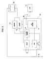
- FIG. 2 is a block diagram of the lubricating oil feeding apparatus according to the present invention.
- FIG. 3 is an algorithm diagram explaining the lubricating oil feeding method according to the present invention.
- FIG. 4 is a waveform diagram explaining the output control timing according to the present invention.
- the automatic lubricating oil feeding apparatus includes a microcomputer 10 capable of storing and computing input data and performing an input/output control, a mode switch MS for determining and inputting discharge time data of lubricating oil to the microcomputer 10, a liquid crystal display (LCD) 11 which is driven by an LCD driver 8 provided in the microcomputer 10, a purge driver 12 which is driven by the maximum output of a power driver 6 provided in the microcomputer 10, a driver 13 which is driven by an output of the power driver 6 corresponding to a selected mode, and an electrochemical reactor 20 receiving its operating power supply B* through the purge driver 12 and the driver 13.
- a microcomputer 10 capable of storing and computing input data and performing an input/output control
- a mode switch MS for determining and inputting discharge time data of lubricating oil to the microcomputer 10
- LCD liquid crystal display
- purge driver 12 which is driven by the maximum output of a power driver 6 provided in the microcomputer
- a driver 13 which is driven by an output of the power driver 6 corresponding to a
- the lubricating oil feeding apparatus is properly installed in a required machine parts. If a user manipulates the mode switch MS to select a discharge mode, the microcomputer 10 performs an operating month input mode (step S1 in FIG. 3), for example, for selecting one of 1, 2, 3, 6, and 12-month modes. If it is determined that the selected mode is a purge mode (step S2 in FIG, 3), the microcomputer 10 turns on its output port (step S3 in FIG. 3) to operate the electrochemical reactor 20 with its maximum electrochemical reaction level.
- the term "on-state of the output port" means a 'LOW' logic level.
- the output of the power driver 6 is applied to the purge driver 12, and the power supply B* flows to the driver 12 through the electrochemical reactor 20, causing the lubricating oil to be discharged.
- the microcomputer 10 performs its control operation in accordance with the corresponding input mode.
- the term "off-state of the output port" means a 'HIGH' logic level.
- the reaction time of the electrochemical reactor 20 is controlled in such a manner that, in order to control the discharge amount of the lubricating oil, the operating time for each selected mode, i.e., the K time, is determined by the amount of the current consumption of the electrochemical reactor 20, which is obtained by computing an expression IxTM ⁇ TC, where I is the amount of current, TC is a unit time, and TM is the output time according to the selected mode.
- the K time for each mode is calculated by multiplying Xt by the efficiency of the gas chamber which is converted from the specific resistance value of the gas chamber in accordance with the passed time.
- step S15 in FIG. 3 the set discharge mode is cleared, and the discharge mode for the minimum time, i.e., for one month, is set under the control of the microcomputer 10 (step S16 in FIG. 3), so that the remaining lubricating oil is completely discharged during the minimum time.
- the power driver 6 and the driver 13 operate for the one-month mode until the power supply B* being supplied thereto is expired.
- the set mode is displayed on the LCD as the number of discharge months, and thus a user can easily recognize the discharge months of the present mode.
Abstract
Description
- The present invention relates to a method and apparatus for automatically feeding lubricating oil to bearing portions of various machine parts. In particular, the present invention relates to a method and apparatus for automatically feeding lubricating oil using a microcomputer whereby when a predetermined time for discharging lubricating oil terminates, a discharge mode for a minimum time, for example, for one month, is set to completely discharge the remaining lubricating oil, and the predetermined discharge time is displayed by a display device.
- Conventionally, an automatic lubricating oil feeding apparatus using gas pressure has been proposed to automatically feed lubricating oil such as grease to bearing portions of the machine parts of various industrial equipments.
- Such an automatic lubricating oil feeding apparatus has advantages in that it can continuously feed lubricating oil to places which need the lubricating oil such as bearings without the necessity of a manual feeding operation.
- According to the conventional lubricating oil feeding apparatus, the lubricating oil is automatically discharged by a piston which moves downward by a diaphragm. This diaphragm is extended to move the piston by gas pressure provided by an electrochemical reactor. The gas reaction time and the gas pressure of the electrochemical reactor are adjusted by a control circuit, and thus the discharge of lubricating oil can be automatically performed extending from several months to several tens of months.
- FIG. 1 is a schematic circuit diagram of a conventional lubricating oil feeding apparatus. Referring to FIG. 1, between an
electrochemical reactor 20 and a driving power supply B+, a plurality of resistors R1 to R5 and a plurality of switches S1 to S5 are connected in series to adjust the current flowing to theelectrochemical reactor 20. A display section for visually indicating the operation of theelectrochemical reactor 20 is composed of a light-emitting diode LED, driving transistors Q1 to Q3, and resistors. - According to the conventional lubricating oil feeding apparatus as constructed above, the amount of current applied to the
electrochemical reactor 20 is varied in accordance with a specific resistance determined by the on/off state of the switches S1 to S5 to adjust the reaction time of the electrochemical reactor (e.g., gas chamber) 20. The reaction time corresponds to the lubricating oil discharge time, and is extended from one month to several months. During the reaction time, the light-emitting diode is turned on to display the operating state of the electrochemical reactor. The electrochemical reaction time is adjusted by controlling the current consumption of the electrochemical reactor and the current consumption is controlled according to the resistance selected by the switches S1 to S5. Accordingly, the conventional apparatus has drawbacks in that the environmental conditions such as the condition inside the bearing portion, the temperature change, etc., cannot be reflected in controlling the lubricating oil discharge time. Further, as time goes by, the internal resistance of the electrochemical reactor (e.g., gas chamber) may vary, causing the current consumption of the reactor also to vary. This causes the proper and accurate discharge of lubricating oil in time and in amount not to be achieved. - Also, according to the conventional apparatus, the predetermined discharge time can be recognized only by checking the on/off state of the switches to cause inconvenience in use. Further, in the event that a portion of the lubricating oil still remains due to the external or internal factors when the predetermined discharge time elapses, a user cannot identify whether or not the amount of the remaining lubricating oil is sufficient for setting of the discharge time again, and thus he can but discard the remaining oil.
- It is an object of the present invention to solve the problems involved in the prior art, and to provide a method and apparatus for automatically feeding lubricating oil whereby a desired discharge time of lubricating oil can be easily determined using a microcomputer.
- It is another object of the present invention to provide a method and apparatus for automatically feeding lubricating oil which can display the determined discharge time of lubricating oil by means of a liquid crystal display to provide convenience in use.
- It is still another object of the present invention to provide a method and apparatus for automatically feeding lubricating oil which can guide an accurate lubricating oil discharge operation with respect to a predetermined discharge time by compensating for the change of the internal resistance of the electrochemical reactor during the discharge time.
- It is still another object of the present invention to provide a method and apparatus for automatically feeding lubricating oil which can completely discharge the remaining lubricating oil by automatically setting a discharge mode for a minimum time when the determined discharge time elapses.
- In one aspect of the present invention, there is provided an automatic lubricating oil feeding apparatus using an electrochemical reactor, the apparatus comprising:
- mode selection means for selecting a discharge mode of lubricating oil;
- a microcomputer for computing a discharge time according to the selected mode and providing to the electrochemical reactor a control signal corresponding to the computed discharge time; and
- a liquid crystal display for displaying the selected mode and/or the computed discharge time under the control of the microcomputer.
- In another aspect of the present invention, there is provided a method of automatically feeding lubricating oil using an electrochemical reactor, the method comprising the steps of:
- determining a discharge time of lubricating oil for each discharge mode to be set;
- controlling the operation of the electrochemical reactor in accordance with the determined discharge time;
- detecting completion of the set discharge mode; and
- setting a discharge mode for a minimum discharge time when the set discharge mode is completed, to rapidly discharge the remaining lubricating oil.
- The above objects, other features, and advantages of the present invention will become more apparent by describing the preferred embodiment thereof with reference to the accompanying drawings, in which:
- FIG. 1 is a schematic circuit diagram of a conventional lubricating oil feeding apparatus.
- FIG. 2 is a block diagram of the lubricating oil feeding apparatus according to the present invention.
- FIG. 3 is an algorithm diagram explaining the lubricating oil feeding method according to the present invention.
- FIG. 4 is a waveform diagram explaining the output control timing according to the present invention.
- Referring to FIG. 2, the automatic lubricating oil feeding apparatus according to the present invention includes a
microcomputer 10 capable of storing and computing input data and performing an input/output control, a mode switch MS for determining and inputting discharge time data of lubricating oil to themicrocomputer 10, a liquid crystal display (LCD) 11 which is driven by anLCD driver 8 provided in themicrocomputer 10, apurge driver 12 which is driven by the maximum output of apower driver 6 provided in themicrocomputer 10, adriver 13 which is driven by an output of thepower driver 6 corresponding to a selected mode, and anelectrochemical reactor 20 receiving its operating power supply B* through thepurge driver 12 and thedriver 13. - The operation of the lubricating oil feeding apparatus according to the present invention as constructed above will be explained with reference to FIGs. 2 to 4.
- The lubricating oil feeding apparatus according to the present invention is properly installed in a required machine parts. If a user manipulates the mode switch MS to select a discharge mode, the
microcomputer 10 performs an operating month input mode (step S1 in FIG. 3), for example, for selecting one of 1, 2, 3, 6, and 12-month modes. If it is determined that the selected mode is a purge mode (step S2 in FIG, 3), themicrocomputer 10 turns on its output port (step S3 in FIG. 3) to operate theelectrochemical reactor 20 with its maximum electrochemical reaction level. Here, the term "on-state of the output port" means a 'LOW' logic level. - As the output port is turned on, the output of the
power driver 6 is applied to thepurge driver 12, and the power supply B* flows to thedriver 12 through theelectrochemical reactor 20, causing the lubricating oil to be discharged. - Meanwhile, if the operating month is inputted instead of determining the purge mode, the
microcomputer 10 performs its control operation in accordance with the corresponding input mode. - Specifically, if the operating time reaches (step S5 in FIG. 3) as a real time counting is performed (step S4 in FIG. 3), a tick clock is generated in the
microcomputer 10 and themicrocomputer 10 performs the determined mode (step S6 in FIG. 3), turning on its output port (step S7 in FIG. 3). Thereafter, themicrocomputer 10 detects whether or not the output time per unit time of each mode is zero (i.e., K time=0) (step S8 in FIG. 3), and if it is detected that the K time is zero, themicrocomputer 10 turns off its output port (step S9 in FIG. 3) to limit the output of thedriver - Accordingly, the reaction time of the
electrochemical reactor 20 is controlled in such a manner that, in order to control the discharge amount of the lubricating oil, the operating time for each selected mode, i.e., the K time, is determined by the amount of the current consumption of theelectrochemical reactor 20, which is obtained by computing an expression IxTM÷TC, where I is the amount of current, TC is a unit time, and TM is the output time according to the selected mode. - If it is assumed that the K time for the 1-month mode is Xt, the K times for other modes can be obtained as the following table, respectively.
Table MODE K TIME DETERMINED DAYS 1 MONTH K = Xt 30 DAYS 2 MONTHS K = Xt * 1/2 * EFFICIENCY 60 DAYS 3 MONTHS K = Xt * 1/3 * EFFICIENCY 90 DAYS 6 MONTHS K = Xt * 1/6 * EFFICIENCY 180 DAYS 12 MONTHS K = Xt * 1/12 * EFFICIENCY 360 DAYS - In the table, the K time for each mode is calculated by multiplying Xt by the efficiency of the gas chamber which is converted from the specific resistance value of the gas chamber in accordance with the passed time.
- Thereafter, if it is determined that the counted days become equal to the predetermined days (step S15 in FIG. 3), the set discharge mode is cleared, and the discharge mode for the minimum time, i.e., for one month, is set under the control of the microcomputer 10 (step S16 in FIG. 3), so that the remaining lubricating oil is completely discharged during the minimum time.
- At this time, the
power driver 6 and thedriver 13 operate for the one-month mode until the power supply B* being supplied thereto is expired. - While the discharge operation is performed, the set mode is displayed on the LCD as the number of discharge months, and thus a user can easily recognize the discharge months of the present mode.
- While the present invention has been described and illustrated herein with reference to the preferred embodiment thereof, it will be understood by those skilled in the art that various changes in form and details may be made therein without departing from the spirit and scope of the invention.
Claims (3)
- An automatic lubricating oil feeding method using an electrochemical reactor, the method comprising the steps of:determining a discharge time of lubricating oil for each discharge mode to be set;controlling the operation of the electrochemical reactor in accordance with the determined discharge time;detecting completion of the set discharge mode; andsetting a discharge mode for a minimum discharge time when the set discharge mode is completed, to rapidly discharge the remaining lubricating oil.
- An automatic lubricating oil feeding apparatus using an electrochemical reactor, the apparatus comprising:a mode selection switch for selecting a discharge mode of lubricating oil;a microcomputer for computing a discharge time according to the selected mode and providing to the electrochemical reactor a control signal corresponding to the computed discharge time; anda liquid crystal display for displaying the selected mode and/or the computed discharge time under the control of the microcomputer.
- An automatic lubricating oil feeding apparatus as claimed in claim 2, further comprising:an liquid crystal display driver for driving the liquid crystal display under the control of the microcomputer;a purge driver for driving the electrochemical reactor with a maximum output under the control of the microcomputer; anda driver for driving the electrochemical reactor in accordance with the selected mode under the control of the micro computer.
Applications Claiming Priority (2)
| Application Number | Priority Date | Filing Date | Title |
|---|---|---|---|
| KR9614738 | 1996-05-06 | ||
| KR1019960014738A KR100189152B1 (en) | 1996-05-06 | 1996-05-06 | Automatic supplying method and system with micom |
Publications (2)
| Publication Number | Publication Date |
|---|---|
| EP0806603A1 true EP0806603A1 (en) | 1997-11-12 |
| EP0806603B1 EP0806603B1 (en) | 2003-07-09 |
Family
ID=19457856
Family Applications (1)
| Application Number | Title | Priority Date | Filing Date |
|---|---|---|---|
| EP97300189A Expired - Lifetime EP0806603B1 (en) | 1996-05-06 | 1997-01-14 | Method and apparatus for automatically feeding lubricating oil using microcomputer |
Country Status (4)
| Country | Link |
|---|---|
| US (1) | US5788012A (en) |
| EP (1) | EP0806603B1 (en) |
| KR (1) | KR100189152B1 (en) |
| DE (1) | DE69723355T2 (en) |
Cited By (6)
| Publication number | Priority date | Publication date | Assignee | Title |
|---|---|---|---|---|
| WO2000036331A1 (en) * | 1998-12-13 | 2000-06-22 | Brückner Maschinenbau GmbH | Method for lubricating transport systems or parts thereof, the use of a lubricating device for carrying out the method, and an appropriate transport system with a corresponding lubricating device |
| EP1104868A3 (en) * | 1999-12-02 | 2002-06-19 | Korea Leading Technology Co., Ltd. | Method of automatically feeding lubricating oil using microcomputer |
| AU2009341462B2 (en) * | 2009-03-05 | 2015-07-02 | Perma-Tec Gmbh & Co. Kg | Method for metered dispensing of lubricant |
| CN107544345A (en) * | 2017-09-28 | 2018-01-05 | 中原工学院 | A kind of train wheel track curvilinear motion intelligent lubricating control system |
| CN107937979A (en) * | 2017-12-11 | 2018-04-20 | 中国电子科技集团公司第四十六研究所 | The Fuzzy Adaptive Control Scheme of vapor phase method crystal growth pressure system |
| CN112210825A (en) * | 2020-09-15 | 2021-01-12 | 中国电子科技集团公司第四十六研究所 | Pressure self-adaptive fuzzy control method for large-flow gas phase method crystal growth |
Families Citing this family (10)
| Publication number | Priority date | Publication date | Assignee | Title |
|---|---|---|---|---|
| US6012551A (en) * | 1995-04-15 | 2000-01-11 | Gerhard Dohring | Apparatus for automatic lubricant delivery |
| KR100272677B1 (en) * | 1998-02-02 | 2001-04-02 | 양 윤 종 | Automatic lubricant supplying system with being centrally managed |
| DE10054712C2 (en) * | 2000-11-04 | 2002-10-24 | Walterscheid Gmbh Gkn | Circuit arrangement for actuating a lubricant dispenser and method therefor |
| DE102007021376B4 (en) * | 2007-05-04 | 2009-10-01 | Perma-Tec Gmbh & Co. Kg | Method for operating a lubricant dispenser |
| US8695763B2 (en) * | 2008-03-26 | 2014-04-15 | Haas Automation, Inc. | Smart machine tool lubrication system |
| DE102009022707B4 (en) * | 2009-03-05 | 2014-03-27 | Perma-Tec Gmbh & Co. Kg | lubricant dispenser |
| KR101284597B1 (en) | 2012-05-08 | 2013-07-10 | 주식회사 루브캡이엔에스 | Controller for controlling automatic supply of lubricating oil in machine equipments |
| DE102012111239B4 (en) * | 2012-11-21 | 2016-08-25 | Perma-Tec Gmbh & Co. Kg | Method for the metered delivery of a lubricant |
| DE102012111376A1 (en) * | 2012-11-23 | 2014-05-28 | Perma-Tec Gmbh & Co. Kg | Method for the metered delivery of lubricating grease by means of a lubricant dispenser |
| CN105508859A (en) * | 2015-12-29 | 2016-04-20 | 中国神华能源股份有限公司 | System for controlling Lincoln pumps |
Citations (4)
| Publication number | Priority date | Publication date | Assignee | Title |
|---|---|---|---|---|
| EP0278138A1 (en) * | 1987-02-11 | 1988-08-17 | ORLITZKY, Anton | Lubricating apparatus |
| US5135499A (en) * | 1989-07-12 | 1992-08-04 | Apcis | Device for delivering a pharmacologically active principle by electrolytic pumping |
| US5381874A (en) * | 1993-10-15 | 1995-01-17 | Caterpillar Inc. | Automatic lubrication control |
| US5425706A (en) * | 1989-02-24 | 1995-06-20 | S. I. Scientific Innovations Ltd. | Dispensing device particularly useful for dispensing nutritional liquids |
Family Cites Families (16)
| Publication number | Priority date | Publication date | Assignee | Title |
|---|---|---|---|---|
| US2852098A (en) * | 1955-11-02 | 1958-09-16 | Albin N Benson | Continual pressure grease cup |
| US3367545A (en) * | 1965-09-15 | 1968-02-06 | Products Res & Chemical Corp | Gas-generating dispenser for viscous materials |
| DE2139771C3 (en) * | 1971-08-09 | 1979-04-26 | Roland 8731 Euerdorf Satzinger | Automatic lubricant dispensing lubricator |
| US4023469A (en) * | 1972-08-09 | 1977-05-17 | United States Steel Corporation | Piston and piston rod construction for pumps and method of flushing piston-type pumps |
| US4023648A (en) * | 1974-05-09 | 1977-05-17 | Anton Orlitzky | Lubricant applicators |
| US4023468A (en) * | 1976-01-09 | 1977-05-17 | Thermo Electron Corporation | Blood pump stroke volume limiter |
| US4445168A (en) * | 1981-06-24 | 1984-04-24 | Houdaille Industries, Inc. | Apparatus and method for micro-computer control of lubrication system |
| NL8501839A (en) * | 1985-06-26 | 1987-01-16 | Skf Ind Trading & Dev | DEVICE FOR DELIVERING A LUBRICANT. |
| US4671386A (en) * | 1985-10-01 | 1987-06-09 | Anton Orlitzky | Lubricating apparatus |
| DE3644207A1 (en) * | 1986-12-23 | 1988-07-07 | Satzinger Gebhard Gmbh Co | DEVICE FOR CONTINUOUSLY DELIVERING LIQUID OR VISCOSE MEDIA, ESPECIALLY LUBRICANTS |
| EP0362328B1 (en) * | 1988-03-16 | 1995-08-09 | WYSSMANN, Max | Lubricant dispenser |
| US5038893A (en) * | 1989-09-25 | 1991-08-13 | Orsco, Inc. | Lubrication monitoring system |
| DE69208477T3 (en) * | 1991-11-22 | 2001-03-01 | Dennis Arthur John Patterson | DELIVERY DEVICE |
| KR0110998Y1 (en) * | 1992-12-01 | 1997-12-22 | Hankuk Lubrication Technology | Device for supplying lubrication oil |
| DE4241073C1 (en) * | 1992-12-05 | 1994-06-01 | Satzinger Gmbh & Co | Dispensing system for dosed discharge esp. of lubricant fluid - has container in which fluid is acted on by gas pressure produced in container and dosing pump connected to container |
| US5622239A (en) * | 1995-07-14 | 1997-04-22 | A.T.S. Electro-Lube Holdings Ltd. | Gear wheel lubricator |
-
1996
- 1996-05-06 KR KR1019960014738A patent/KR100189152B1/en not_active IP Right Cessation
-
1997
- 1997-01-14 DE DE69723355T patent/DE69723355T2/en not_active Expired - Fee Related
- 1997-01-14 EP EP97300189A patent/EP0806603B1/en not_active Expired - Lifetime
- 1997-02-05 US US08/794,897 patent/US5788012A/en not_active Expired - Lifetime
Patent Citations (4)
| Publication number | Priority date | Publication date | Assignee | Title |
|---|---|---|---|---|
| EP0278138A1 (en) * | 1987-02-11 | 1988-08-17 | ORLITZKY, Anton | Lubricating apparatus |
| US5425706A (en) * | 1989-02-24 | 1995-06-20 | S. I. Scientific Innovations Ltd. | Dispensing device particularly useful for dispensing nutritional liquids |
| US5135499A (en) * | 1989-07-12 | 1992-08-04 | Apcis | Device for delivering a pharmacologically active principle by electrolytic pumping |
| US5381874A (en) * | 1993-10-15 | 1995-01-17 | Caterpillar Inc. | Automatic lubrication control |
Cited By (6)
| Publication number | Priority date | Publication date | Assignee | Title |
|---|---|---|---|---|
| WO2000036331A1 (en) * | 1998-12-13 | 2000-06-22 | Brückner Maschinenbau GmbH | Method for lubricating transport systems or parts thereof, the use of a lubricating device for carrying out the method, and an appropriate transport system with a corresponding lubricating device |
| EP1104868A3 (en) * | 1999-12-02 | 2002-06-19 | Korea Leading Technology Co., Ltd. | Method of automatically feeding lubricating oil using microcomputer |
| AU2009341462B2 (en) * | 2009-03-05 | 2015-07-02 | Perma-Tec Gmbh & Co. Kg | Method for metered dispensing of lubricant |
| CN107544345A (en) * | 2017-09-28 | 2018-01-05 | 中原工学院 | A kind of train wheel track curvilinear motion intelligent lubricating control system |
| CN107937979A (en) * | 2017-12-11 | 2018-04-20 | 中国电子科技集团公司第四十六研究所 | The Fuzzy Adaptive Control Scheme of vapor phase method crystal growth pressure system |
| CN112210825A (en) * | 2020-09-15 | 2021-01-12 | 中国电子科技集团公司第四十六研究所 | Pressure self-adaptive fuzzy control method for large-flow gas phase method crystal growth |
Also Published As
| Publication number | Publication date |
|---|---|
| DE69723355D1 (en) | 2003-08-14 |
| KR100189152B1 (en) | 1999-06-01 |
| EP0806603B1 (en) | 2003-07-09 |
| KR970075632A (en) | 1997-12-10 |
| DE69723355T2 (en) | 2004-05-27 |
| US5788012A (en) | 1998-08-04 |
Similar Documents
| Publication | Publication Date | Title |
|---|---|---|
| EP0806603B1 (en) | Method and apparatus for automatically feeding lubricating oil using microcomputer | |
| US5251125A (en) | User interface for a process control device | |
| JP2640682B2 (en) | Abnormal display method of machining fluid temperature of wire electric discharge machine | |
| EP0245113A2 (en) | Air condition monitor unit | |
| US7110896B2 (en) | System and method for displaying battery status and other parameters of a portable electronic device in a power-off state | |
| TW200717429A (en) | EL display device and the method for detecting the same | |
| MY119206A (en) | Method of and apparatus for setting up an electronic device | |
| EP0594006A1 (en) | Battery-powered data processor | |
| EP0115178B1 (en) | Digital controller | |
| US5784295A (en) | Method and apparatus for determining residual battery voltage | |
| CN107589568B (en) | Automatic learning and detecting device and method for LED lamp string | |
| US4365289A (en) | Method and control system for controlling apparatus | |
| CN1058869A (en) | Television receiver | |
| CN215067236U (en) | Testing device and contrast testing device for rotary electromagnet | |
| KR100547730B1 (en) | How to display charge remaining time | |
| KR100356700B1 (en) | Device for testing a lithium ion battery pack of notebook computer | |
| CN215067237U (en) | Control device of rotary electromagnet testing device | |
| US4932244A (en) | Display device for an engine-equipped machine | |
| KR20010107996A (en) | Control device | |
| CN214703931U (en) | Light source testing device | |
| EP0102373B1 (en) | Step sequence control apparatus | |
| KR100591038B1 (en) | LCD display with display density adjustment | |
| JPH0655133U (en) | Liquid crystal display drive controller | |
| CN218208947U (en) | Lubricating pump liquid level control system | |
| KR20020061382A (en) | A programmable dc power supply |
Legal Events
| Date | Code | Title | Description |
|---|---|---|---|
| PUAI | Public reference made under article 153(3) epc to a published international application that has entered the european phase |
Free format text: ORIGINAL CODE: 0009012 |
|
| AK | Designated contracting states |
Kind code of ref document: A1 Designated state(s): DE FR GB |
|
| 17P | Request for examination filed |
Effective date: 19980313 |
|
| 17Q | First examination report despatched |
Effective date: 20020222 |
|
| GRAH | Despatch of communication of intention to grant a patent |
Free format text: ORIGINAL CODE: EPIDOS IGRA |
|
| GRAH | Despatch of communication of intention to grant a patent |
Free format text: ORIGINAL CODE: EPIDOS IGRA |
|
| GRAA | (expected) grant |
Free format text: ORIGINAL CODE: 0009210 |
|
| AK | Designated contracting states |
Designated state(s): DE FR GB |
|
| REG | Reference to a national code |
Ref country code: GB Ref legal event code: FG4D |
|
| REF | Corresponds to: |
Ref document number: 69723355 Country of ref document: DE Date of ref document: 20030814 Kind code of ref document: P |
|
| PG25 | Lapsed in a contracting state [announced via postgrant information from national office to epo] |
Ref country code: GB Free format text: LAPSE BECAUSE OF NON-PAYMENT OF DUE FEES Effective date: 20040114 |
|
| PLBE | No opposition filed within time limit |
Free format text: ORIGINAL CODE: 0009261 |
|
| STAA | Information on the status of an ep patent application or granted ep patent |
Free format text: STATUS: NO OPPOSITION FILED WITHIN TIME LIMIT |
|
| ET | Fr: translation filed | ||
| 26N | No opposition filed |
Effective date: 20040414 |
|
| PG25 | Lapsed in a contracting state [announced via postgrant information from national office to epo] |
Ref country code: DE Free format text: LAPSE BECAUSE OF NON-PAYMENT OF DUE FEES Effective date: 20040803 |
|
| GBPC | Gb: european patent ceased through non-payment of renewal fee |
Effective date: 20040114 |
|
| REG | Reference to a national code |
Ref country code: FR Ref legal event code: ST Effective date: 20080229 |
|
| PG25 | Lapsed in a contracting state [announced via postgrant information from national office to epo] |
Ref country code: FR Free format text: LAPSE BECAUSE OF NON-PAYMENT OF DUE FEES Effective date: 20040131 |