EP0806672A2 - Method and apparatus for handling a sample - Google Patents
Method and apparatus for handling a sample Download PDFInfo
- Publication number
- EP0806672A2 EP0806672A2 EP97303093A EP97303093A EP0806672A2 EP 0806672 A2 EP0806672 A2 EP 0806672A2 EP 97303093 A EP97303093 A EP 97303093A EP 97303093 A EP97303093 A EP 97303093A EP 0806672 A2 EP0806672 A2 EP 0806672A2
- Authority
- EP
- European Patent Office
- Prior art keywords
- container
- sample
- cuvette
- needle
- cuvettes
- Prior art date
- Legal status (The legal status is an assumption and is not a legal conclusion. Google has not performed a legal analysis and makes no representation as to the accuracy of the status listed.)
- Withdrawn
Links
Images


Classifications
-
- G—PHYSICS
- G01—MEASURING; TESTING
- G01N—INVESTIGATING OR ANALYSING MATERIALS BY DETERMINING THEIR CHEMICAL OR PHYSICAL PROPERTIES
- G01N35/00—Automatic analysis not limited to methods or materials provided for in any single one of groups G01N1/00 - G01N33/00; Handling materials therefor
- G01N35/02—Automatic analysis not limited to methods or materials provided for in any single one of groups G01N1/00 - G01N33/00; Handling materials therefor using a plurality of sample containers moved by a conveyor system past one or more treatment or analysis stations
-
- G—PHYSICS
- G01—MEASURING; TESTING
- G01N—INVESTIGATING OR ANALYSING MATERIALS BY DETERMINING THEIR CHEMICAL OR PHYSICAL PROPERTIES
- G01N33/00—Investigating or analysing materials by specific methods not covered by groups G01N1/00 - G01N31/00
- G01N33/48—Biological material, e.g. blood, urine; Haemocytometers
- G01N33/483—Physical analysis of biological material
- G01N33/487—Physical analysis of biological material of liquid biological material
- G01N33/49—Blood
- G01N33/4905—Determining clotting time of blood
-
- G—PHYSICS
- G01—MEASURING; TESTING
- G01N—INVESTIGATING OR ANALYSING MATERIALS BY DETERMINING THEIR CHEMICAL OR PHYSICAL PROPERTIES
- G01N35/00—Automatic analysis not limited to methods or materials provided for in any single one of groups G01N1/00 - G01N33/00; Handling materials therefor
- G01N35/00584—Control arrangements for automatic analysers
- G01N35/00594—Quality control, including calibration or testing of components of the analyser
- G01N35/00613—Quality control
- G01N35/00663—Quality control of consumables
- G01N2035/00673—Quality control of consumables of reagents
Definitions
- the present invention relates to a method and apparatus for use in handling a sample.
- the present invention relates to a hemostasis analyzer system useful for measuring clotting times on samples of human plasma.
- Analyses for Prothrombin Time (PT), Activated Partial Thromboplastin Time (aPTT), Thrombin Clotting Time (TCT), Fibrinogen and Factor Assays may be performed using this invention. Additional tests may be performed if data is provided as an input to the system. The system is intended for in-vitro diagnostic use.
- the system automatically transfers samples from test tubes to cuvettes, automatically prepares dilutions and mixtures of samples and reagents, incubates the mixtures and provides optical density measurements of the reaction between the sample and the reagent.
- Multiple reagent pumps deliver chilled reagents such as for PT, aPTT, TCT (Thrombin Clotting Time), Fibrinogen, and Factor Assays (Factors II, V, VII, VIII, IX, X, XI and XII).
- the invention has three primary parts which are a computer, a sample handler and an optics handler.
- the computer generally identified as the CPU controls the operation of the entire system.
- the sample handler performs the automated functions necessary to prepare the raw samples for testing.
- the optics handler controls the processing of the samples with reagents and optically obtains the results.
- test tubes each with a stopper at the top and bar codes on the side, are loaded into test tube racks.
- the system reads the bar codes from the test tubes although the system permits manual data input.
- the system determines whether or not a test tube is present in the test tube rack, ensures that the reagent vials contain proper reagents for the desired test, and automatically primes the pump assembly.
- a liquid detection system obtains samples from the test tubes, with the samples being withdrawn via a needle.
- a cuvette carousel will release one cuvette and confirm that the cuvette is properly oriented and positioned to receive the sample from the needle.
- the cuvette is automatically transported to the optics handler which confirms the presence of a cuvette.
- reagents are placed in the cuvette and the optics detects when reactions (coagulation) occur in the cuvettes. These reactions are timed.
- the system 10 in basic form includes a computer (sometimes identified as a CPU) 12 including a monitor 14, a primary display device 16, a keyboard 19, a sample handler 100 and an optics handler 200.
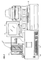
- the physical arrangement of the system 10 is illustrated in greater detail in Figure 2, including the touch screen display 16, a printer 17, a disk drive, system power switch 20, secondary display 22, and a carousel 110.
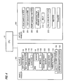
- Various functional units of the analyzer are shown in block diagrammatic form in Figure 3 including an 8-channel optical controller 24, a 4-channel temperature controller 26, a sample handler (controlling sample delivery and transport), three independent motor control modules 28, and the computer 12 for user interface and data storage.
- the temperature controller 26 includes a display 22, an incubator heater 32, an optics heater 34, a factor cooler 36 and a reagent cooler 38.
- "Y" and "Z" position encoders 40, 42 and a fluid sensor 44 are used by the sample handler to withdraw exact sample amounts from test tubes, and deposit samples into a cuvette using a needle 118.
- a diluter 46 performs the dilutions required by each type of test.
- Manual user input is through the touch screen 16 and keyboard 19 of Figure 2 including selection of the specific test, starting or stopping automatic sequence of operations, priming or purging pumps, etc. Data such as identification of the hospital patient may be entered, for example through a keyboard 19, bar code reader 50, or a network.
- the processor or computer 12 which operates the system is preferably comprised of cards located within the card cage 52.
- the preferred cards within the card cage include a touch screen interface, b) embedded PC, c) motor controller (1-8), d) motor controller (9-16), e) motor controller (17-24), f) sample handler, g) temperature controller, and h) optics controller as shown in Figure 3.
- the card cage contains the other circuits for operating the apparatus of the present invention.
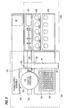
- the sample handler system 100 contains racks 102, 104, the bar code reader 50 referred to previously, a test tube detector 108, a cuvette carousel 110 with vertical racks of cuvettes, an arm 114 with a related fluid sensor 44 and a needle 118, a waste container sensor system 120, syringe motor 122, peristaltic pumps 124, cuvette delivery system 126 and a cuvette orientation verification system 128.
- the sample handler controls motion in the Y and Z coordinate planes moving the test tube racks 102 and the factor racks 104 in the X direction to position test tubes beneath the arm assembly 114 and in particular, the needle 118 of the arm assembly.
- the arm assembly moves the needle in the Y and Z planes.
- the sample handler includes peristaltic pumps 124 and the syringe 121 with the accompanying syringe motor 122.
- peristaltic pumps 124 Preferably there are two pumps, one for flushing the inside of the needle through the syringe system and the second for pumping water to a wash basin 130 that is used to clean the outside of the needle.
- the wash basin In the wash basin, the needle is cleaned with a continuous flow of cleaning solution.
- the cuvette carousel 110 holds ten stacks of ten cuvettes each.
- the cuvette delivery assembly 126 includes those parts which allow the cuvette to be fed ultimately from the carousel to the chute and to the optics handler.
- the cuvette verification/orientation system 128 sense that the cuvette is in the proper position and orientation before the cuvette is permitted to receive samples and reagents.
- the carousel 110 includes the series of vertical racks or channels 140 and two partially-full racks, with cuvettes 112, are illustrated.
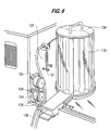
- the factor/buffer rack 104 holds the factors (chemical reagents) and buffers that are necessary in performing the various tests.
- the factors/buffers are maintained in bottles 105 in a position such that the needle, controlled by the arm assembly, may obtain the necessary quantities of factors or buffers.
- the test tube rack 102 holds the blood samples in test tubes 103.
- the bar code reader 50 which is interfaced to the sample handler will input data from bar coded labels on the test tubes 103 and confirms the presence or absence of light from the bar code to determine whether a test tube 103 is present.
- the fluid sensor 44 together with the arm assembly and needle, sense fluid and assist in obtaining or withdrawing the proper amount of fluid from a test tube 103 in the tube rack 104, or from a factor bottle or buffer bottle in the factor/buffer rack 104.
- a syringe 121 and a syringe motor 122 are shown for handling the exact quantities of fluid that the needle will withdraw from the test tubes or factor or buffer solutions in the factor/buffer racks.
- the syringe and syringe motor system is extremely precise and is connected to the needle through plastic piping.
- the cuvette carousel 110 which is covered by a cuvette carousel lid 134, holds vertical racks of cuvettes.
- the cuvette carousel is circular and is loaded with empty cuvettes from one side and the cuvettes are discharged from the opposite side for use by the system.
- the pumps 124 have fittings and delivery tubes 136, one of which is connected to supply the wash basin 130 which washes the outside of the needle. Waste tubes 138 transfer fluid away from the sample handler.
- the wash basin forces a solution up against gravity and the needle is lowered into the running solution.
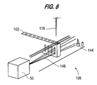
- the test tube detector system 108 for determining the presence or absence of a test tube 103 uses bar code reader 50 which reads bar codes on the factors/buffers bottles 105 and on patient test tubes 103.
- the light from the bar code reader is used to determine the presence or absence of a test tube and the test tube detection system 108 includes a photodetector 144. If there are no obstructions between the light source and a photodetector, the light beam 148 from the bar code reader is received and a voltage threshold is set in the photodetector. This is referred to as initializing the bar code reader.
- a test tube rack moves in position, if a bar code cannot be read and the photodetector receives the same amount of light as when initialized, then a tube is "not" present. However, if, the photodetector receives a lesser amount of light, then a test tube is present.
- the fluid sensor or level detector system 44 operates in conjunction with the arm 114 and needle 118.
- the fluid level detector operates in the RF range and only the needle makes contact with the fluid.
- the needle 118 pierces the rubber stopper on the tube and then functions as the sensor.
- the preferred fluid detector is based on a radio frequency CMOS oscillator 150 having an output frequency optimally at 4 mhz. This frequency is sensitive to fluid and lacks sensitivity to surrounding metal used to build the instrument in which the fluid level detector is utilized. Variations from this frequency are possible.
- the oscillator output is coupled to the sample needle via a 50 ohm shielded cable.
- the shield extends to the sample needle thus reducing radiated RF energy to a few microwatts because of the needle length which is extremely short.
- the oscillator output is capacitively coupled 152 to a rectifier, filtered, and then fed into a comparator 154.
- the sine wave oscillator voltage output drops.
- the comparator 154 is sampling, causing it to compare.
- the comparator reference voltage 156 is set via a resistor divider and the comparator compare point is set according to the depth desired in the sample tube.
- a buffered analog output voltage 158 is derived from the rectified oscillator voltage which is fed into an analog to digital converter. This allows the raw data from the level sensor to be interpreted by software to greatly increase the dynamic range of the sensor.
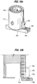
- the delivery system 126 ejects or releases a cuvette 112 from the carousel or turret 110.
- a plunger 160 and compression spring 162 are positioned in a spring block housing 163 which is mounted to the outside of the carousel 110. The plunger moves laterally from a first position under a rack 140 in the carousel ( Figure 10b) to a second position inwardly of the rack ( Figure 10c). It is necessary to eliminate the weight of multiple, vertically oriented cuvettes from the bottom cuvette.
- the plunger 160 initially prevents the release of the cuvettes.
- the plunger includes a roller bearing 170 which contacts an actuator rod 166 in the spring block housing 163. In this position, the compression spring 162 in the housing is moved out of contact with the vertical column of cuvettes.
- the roller bearing 170 moves clear of the actuator rod 166.
- the compression spring 162 biases the actuator rod into the downward position ( Figure 10c) and moves toward the vertical rack of cuvettes to contact the second cuvette from the bottom and urges the second cuvette against the carousel rack. This holds the second cuvette, and all the cuvettes above the second cuvette, in the rack while relieving the pressure on the bottom cuvette. Then only the bottom cuvette is released into a cuvette chute 164.
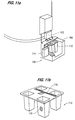
- positive cuvette orientation system 128 includes two photodetectors 172, 174 positioned at right angles to each other with one photodetector 172 positioned above the chute 164 and the other photodetector 174 positioned adjacent the chute.
- the individual cuvette 112 includes a first portion 176 on the flat top of the cuvette and a second portion 178 on a side wall of the cuvette. As the cuvette is discharged from the carousel and moves into the chute 164, the cuvette moves beneath a first photodetector 172 which reflects a beam of light off the flat top portion 176 of the cuvette top surface.
- a transverse beam (across the direction of travel within the chute) is generated from the second photodetector which is reflected back from the side wall 178 only if the cuvette is properly aligned. If both photodetectors receive positive signals, this is a confirmation that a cuvette is properly oriented. Any other condition generates an error signal to prevent any attempt at placing samples into the cuvette.
- the optics handler 200 includes a variety of subsystems which perform various functions including reading sample optics 202 and calculating tests 204.
- the optics handler controls the pump assembly motors 206 for pumping reagents, the stir motors 208 for stirring the reagents, the transport belt 210, the vial level detectors 212, heaters and coolers 216.
- the optics handler 200 performs the clot analyzing functions of the invention.
- a delivery or transport belt 210 receives cuvettes from the chute 164 and moves the cuvettes.
- the delivery belt uses photodetectors to verify the proper positioning of the cuvettes along the belt as is conventional.
- the cuvettes While the cuvettes are moved along this belt, the cuvettes are being heated and it is preferred that the cuvettes and reagents reach a stable and optimum temperature of 37°C before the tests are actually performed.
- the belt is moved along at the speed necessary for the desired test and thus the speed is controlled by the laboratory technician selecting the specific test. It is within the skill of the art to program the transport speed based upon the test selected, such information being easily stored in a look up table. Thus the belt speed changes depending on the test which has been selected, and the time that the cuvette travels along the belt will change depending upon the test and user inputs.
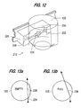
- a non-invasive level detector for determining the levels of reagent bottles uses the properties of light and occlusion and works with both opaque and clear liquids.
- an optic block 226 is positioned adjacent a bottle or vat 105 of reagent.
- a LED transmitter 228 and photodetector 230 are used in conjunction with a collimator hole 232 formed in the optic block.
- the narrow light beam 234, such as from an LED or HeNE laser is directed through a chord of a clear polystyrene container or bottle 105.
- the beam of light cannot travel through the diameter of the vat but must be off-center, e.g., as a chord 235 of a circle in Figure 13a.
- the beam deflects as at 236 due to the optical density of the liquid.
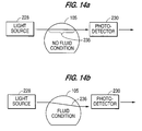
- the deflection (or diffraction) diverts the beam away from the photodetector 230 at the opposite side of the vat and the photodetector will not receive the beam.
- the photodetector receives the beam of light, i.e., the light beam is not deflected. Therefore, the preferred detection system indicates the absence of a vat and the presence or absence of fluid if the vat is present.
- Figure 12 illustrates the physical arrangement of the liquid level detection system
- Figures 13a and 14a indicate the presence of a container 105 which is empty (or the absence of a container)
- Figures 13b and 14b indicate the presence of liquid at the vertical level (height) of the detector.
- the height of the detector may be selected to insure sufficient fluid for the quantity of tests which can be performed without further intervention by the laboratory technician.
- the pump assembly system 206 transfers fluids from the reagent vials or bottles 105 to the cuvettes.
- the volume of reagent transferred to the cuvettes is preferably an exact amount of reagent which is accomplished by using exact volume tubing, that is, plastic pipes which have been tested so that a certain length of the pipe holds exactly the volume of reagent that is needed for a particular test.
- Autopriming fills the delivery tubes with reagent.
- a standard cuvette 112 with four wells is discharged from the carousel and transported by the belt 210 until two of the wells are positioned under two delivery tubes of the specified reagent. At this area is a standard photodetection system used for timing the formation of a clot.
- the system initializes or "nulls" the light change caused by the empty cuvette in the optics path.
- a predetermined threshold is set by the software for detecting converted analog readings from the optics detector. This is referred to as a z-axis threshold value for the photodetection system, the z-axis referring to the vertical axis when the system is viewed from the front as is conventional.
- the associated pump 218 turns for a predetermined number of cycles, moving fluid into the first delivery tube. After a few revolutions any fluid (reagent) is now ejected into the cuvette.
- the photodetection system checks for the presence of fluid in the first cuvette well by measuring the change of light intensity at the threshold z-axis value.
- first reagent pump has been primed so that the desired amount of reagent (using the exact volume delivery tube) will be pumped into a subsequent cuvette when an actual sample is being tested. Then the autopriming is repeated for each reagent. The reagents used for priming are then discarded into the waste area 120.
- Thermal control in this invention is achieved using an embedded algorithm with a microprocessor based control unit to monitor and adjust the temperature of the various liquids used by this invention.
- the embedded algorithm requires:
- the "current temperature” variable is moved to the "previous temperature” variable and the “current temperature” is updated from the averaged value sent from the interrupt event.
- the “current direction” is computed by subtracting the "previous temperature” from the "current temperature”.
- the need to regulate is determined by comparing "current temperature" to the safety limits. Outside of the safety limits the algorithm removes all drive from the physical device and does no further function to determine regulation. If the temperature is within safety limits the algorithm determines whether to cool (drive to a lesser temperature) or heat (drive to a greater temperature) based on information provided by the external memory interface.
- error accumulator is added to insure that the maximum rate added (or subtracted) to the "pulse width value" provides smooth power addition (or subtraction) to the device under control
- the thermal control algorithm has the benefit that it can be configured to drive either heating or cooling devices, it has built in safety devices in the event of loss of sensor input, and it uses a simplified integrator/differentiator to allow for a variety of thermal masses to be regulated.
Abstract
Description
- The present invention relates to a method and apparatus for use in handling a sample.
- More particularly the present invention relates to a hemostasis analyzer system useful for measuring clotting times on samples of human plasma. Analyses for Prothrombin Time (PT), Activated Partial Thromboplastin Time (aPTT), Thrombin Clotting Time (TCT), Fibrinogen and Factor Assays (Factors II, V, VII, VIII, IX, X, XI and XII) may be performed using this invention. Additional tests may be performed if data is provided as an input to the system. The system is intended for in-vitro diagnostic use.
- The system automatically transfers samples from test tubes to cuvettes, automatically prepares dilutions and mixtures of samples and reagents, incubates the mixtures and provides optical density measurements of the reaction between the sample and the reagent. Multiple reagent pumps deliver chilled reagents such as for PT, aPTT, TCT (Thrombin Clotting Time), Fibrinogen, and Factor Assays (Factors II, V, VII, VIII, IX, X, XI and XII).
- The invention has three primary parts which are a computer, a sample handler and an optics handler. The computer generally identified as the CPU controls the operation of the entire system. The sample handler performs the automated functions necessary to prepare the raw samples for testing. The optics handler controls the processing of the samples with reagents and optically obtains the results.
- A series of test tubes each with a stopper at the top and bar codes on the side, are loaded into test tube racks. The system reads the bar codes from the test tubes although the system permits manual data input. The system determines whether or not a test tube is present in the test tube rack, ensures that the reagent vials contain proper reagents for the desired test, and automatically primes the pump assembly. Next, a liquid detection system obtains samples from the test tubes, with the samples being withdrawn via a needle. A cuvette carousel will release one cuvette and confirm that the cuvette is properly oriented and positioned to receive the sample from the needle. The cuvette is automatically transported to the optics handler which confirms the presence of a cuvette. Then, reagents are placed in the cuvette and the optics detects when reactions (coagulation) occur in the cuvettes. These reactions are timed.
- The present invention will now be further described, by way of example, with reference to the accompanying drawings, in which:
- Figure 1 is a diagram of the primary components of the automated hemostasis analyzer;
- Figure 2 is an illustration of the physical arrangement of the components of the system;
- Figure 3 is a detailed schematic of the processor;
- Figure 4 is a block diagram of the sample handler and the optics handler;
- Figure 5 is a detailed schematic of the sampler handler and the optics handler.
- Figure 6 illustrates part of the sampler handler, showing the cuvette carousel, the syringe system, and the pumps;
- Figure 7 illustrates a part of the sampler handler, showing the test tube racks and the factor/buffer rack;
- Figure 8 is a diagram of the test tube detection system.
- Figure 9 is a schematic of the RF fluid level sensing circuit;
- Figure 10a is an illustration of the cuvette carousel;
- Figure 10b is an illustration of a side-view of the cuvette carousel in the front loading position;
- Figure 10c is an illustration of the cuvette carousel in the back loading position;
- Figure 11a is an illustration of the cuvette orientation/verification system;
- Figure 11b is another illustration of the cuvette orientation/verification system;
- Figure 12 is an illustration of the noninvasive method of reagent level detecting;
- Figure 13a is an illustration of a step in the reagent level detecting method;
- Figure 13b is an illustration of a second step in the reagent level detecting method.
- Figure 14a is an illustration of the reagent level detection of the absence of fluid; and
- Figure 14b is an illustration of the reagent level detection of the presence of fluid.
- Referring first to Figure 1, the
system 10 in basic form includes a computer (sometimes identified as a CPU) 12 including amonitor 14, aprimary display device 16, akeyboard 19, asample handler 100 and anoptics handler 200. The physical arrangement of thesystem 10 is illustrated in greater detail in Figure 2, including thetouch screen display 16, aprinter 17, a disk drive,system power switch 20,secondary display 22, and acarousel 110. Various functional units of the analyzer are shown in block diagrammatic form in Figure 3 including an 8-channeloptical controller 24, a 4-channel temperature controller 26, a sample handler (controlling sample delivery and transport), three independentmotor control modules 28, and thecomputer 12 for user interface and data storage. Thetemperature controller 26 includes adisplay 22, anincubator heater 32, anoptics heater 34, afactor cooler 36 and areagent cooler 38. "Y" and "Z" position encoders 40, 42 and afluid sensor 44 are used by the sample handler to withdraw exact sample amounts from test tubes, and deposit samples into a cuvette using aneedle 118. Adiluter 46 performs the dilutions required by each type of test. Manual user input is through thetouch screen 16 andkeyboard 19 of Figure 2 including selection of the specific test, starting or stopping automatic sequence of operations, priming or purging pumps, etc. Data such as identification of the hospital patient may be entered, for example through akeyboard 19,bar code reader 50, or a network. - Referring next to Figure 5 the processor or
computer 12 which operates the system is preferably comprised of cards located within thecard cage 52. The preferred cards within the card cage include a touch screen interface, b) embedded PC, c) motor controller (1-8), d) motor controller (9-16), e) motor controller (17-24), f) sample handler, g) temperature controller, and h) optics controller as shown in Figure 3. The card cage contains the other circuits for operating the apparatus of the present invention. - Referring generally to Figures 4, the
sample handler system 100 containsracks bar code reader 50 referred to previously, atest tube detector 108, acuvette carousel 110 with vertical racks of cuvettes, anarm 114 with arelated fluid sensor 44 and aneedle 118, a wastecontainer sensor system 120,syringe motor 122,peristaltic pumps 124,cuvette delivery system 126 and a cuvetteorientation verification system 128. The sample handler controls motion in the Y and Z coordinate planes moving thetest tube racks 102 and the factor racks 104 in the X direction to position test tubes beneath thearm assembly 114 and in particular, theneedle 118 of the arm assembly. The arm assembly moves the needle in the Y and Z planes. Alternate configurations moving the tubes or needle in X, Y and Z direction are possible. The movements are performed with stepper motors and encoders may be used for more accurate positioning. In the preferred embodiment, encoders 40, 42 are used for the Y and Z coordinate positions of the needle in the arm assembly. - The sample handler includes
peristaltic pumps 124 and thesyringe 121 with the accompanyingsyringe motor 122. Preferably there are two pumps, one for flushing the inside of the needle through the syringe system and the second for pumping water to awash basin 130 that is used to clean the outside of the needle. In the wash basin, the needle is cleaned with a continuous flow of cleaning solution. - Preferably the
cuvette carousel 110, holds ten stacks of ten cuvettes each. Thecuvette delivery assembly 126 includes those parts which allow the cuvette to be fed ultimately from the carousel to the chute and to the optics handler. The cuvette verification/orientation system 128 sense that the cuvette is in the proper position and orientation before the cuvette is permitted to receive samples and reagents. Referring briefly to Figure 7 thecarousel 110 includes the series of vertical racks orchannels 140 and two partially-full racks, withcuvettes 112, are illustrated. - The factor/
buffer rack 104 holds the factors (chemical reagents) and buffers that are necessary in performing the various tests. The factors/buffers are maintained inbottles 105 in a position such that the needle, controlled by the arm assembly, may obtain the necessary quantities of factors or buffers. Thetest tube rack 102 holds the blood samples in test tubes 103. - The
bar code reader 50 which is interfaced to the sample handler will input data from bar coded labels on the test tubes 103 and confirms the presence or absence of light from the bar code to determine whether a test tube 103 is present. Thefluid sensor 44, together with the arm assembly and needle, sense fluid and assist in obtaining or withdrawing the proper amount of fluid from a test tube 103 in thetube rack 104, or from a factor bottle or buffer bottle in the factor/buffer rack 104. In Figure 6, asyringe 121 and asyringe motor 122 are shown for handling the exact quantities of fluid that the needle will withdraw from the test tubes or factor or buffer solutions in the factor/buffer racks. The syringe and syringe motor system is extremely precise and is connected to the needle through plastic piping. Thecuvette carousel 110, which is covered by acuvette carousel lid 134, holds vertical racks of cuvettes. The cuvette carousel is circular and is loaded with empty cuvettes from one side and the cuvettes are discharged from the opposite side for use by the system. Thepumps 124 have fittings anddelivery tubes 136, one of which is connected to supply thewash basin 130 which washes the outside of the needle.Waste tubes 138 transfer fluid away from the sample handler. The wash basin forces a solution up against gravity and the needle is lowered into the running solution. - Referring to Figure 8, the test
tube detector system 108 for determining the presence or absence of a test tube 103 usesbar code reader 50 which reads bar codes on the factors/buffers bottles 105 and on patient test tubes 103. The light from the bar code reader is used to determine the presence or absence of a test tube and the testtube detection system 108 includes aphotodetector 144. If there are no obstructions between the light source and a photodetector, thelight beam 148 from the bar code reader is received and a voltage threshold is set in the photodetector. This is referred to as initializing the bar code reader. A test tube rack moves in position, if a bar code cannot be read and the photodetector receives the same amount of light as when initialized, then a tube is "not" present. However, if, the photodetector receives a lesser amount of light, then a test tube is present. - Referring to Figure 9, the fluid sensor or
level detector system 44 operates in conjunction with thearm 114 andneedle 118. The fluid level detector operates in the RF range and only the needle makes contact with the fluid. Thus theneedle 118 pierces the rubber stopper on the tube and then functions as the sensor. The preferred fluid detector is based on a radiofrequency CMOS oscillator 150 having an output frequency optimally at 4 mhz. This frequency is sensitive to fluid and lacks sensitivity to surrounding metal used to build the instrument in which the fluid level detector is utilized. Variations from this frequency are possible. The oscillator output is coupled to the sample needle via a 50 ohm shielded cable. The shield extends to the sample needle thus reducing radiated RF energy to a few microwatts because of the needle length which is extremely short. The oscillator output is capacitively coupled 152 to a rectifier, filtered, and then fed into acomparator 154. When the needle contacts the fluid and is capacitively coupled to ground, the sine wave oscillator voltage output drops. Thus as the needle comes into contact with fluid in a sample tube, the oscillator output is "pulled" down thereby reducing the DC voltage thecomparator 154 is sampling, causing it to compare. Thecomparator reference voltage 156 is set via a resistor divider and the comparator compare point is set according to the depth desired in the sample tube. The less sensitive the comparator is set, the deeper into the sample the needle must travel for the "pull" on the oscillator to cause a compare condition. A bufferedanalog output voltage 158 is derived from the rectified oscillator voltage which is fed into an analog to digital converter. This allows the raw data from the level sensor to be interpreted by software to greatly increase the dynamic range of the sensor. - After the
needle 118 penetrates the stopper and thefluid sensor system 44 confirms that the needle has reached the fluid in the test tube, the fluid is withdrawn through the needle to be deposited into a cuvette. Referring to Figures 10a, 10b and 10c, thedelivery system 126 ejects or releases acuvette 112 from the carousel orturret 110. Aplunger 160 andcompression spring 162 are positioned in aspring block housing 163 which is mounted to the outside of thecarousel 110. The plunger moves laterally from a first position under arack 140 in the carousel (Figure 10b) to a second position inwardly of the rack (Figure 10c). It is necessary to eliminate the weight of multiple, vertically oriented cuvettes from the bottom cuvette. Theplunger 160 initially prevents the release of the cuvettes. The plunger includes aroller bearing 170 which contacts anactuator rod 166 in thespring block housing 163. In this position, thecompression spring 162 in the housing is moved out of contact with the vertical column of cuvettes. - As the plunger is moved to the left as indicated by the arrow in Figure 10c, the
roller bearing 170 moves clear of theactuator rod 166. Thecompression spring 162 biases the actuator rod into the downward position (Figure 10c) and moves toward the vertical rack of cuvettes to contact the second cuvette from the bottom and urges the second cuvette against the carousel rack. This holds the second cuvette, and all the cuvettes above the second cuvette, in the rack while relieving the pressure on the bottom cuvette. Then only the bottom cuvette is released into acuvette chute 164. Then the plunger moves forward and returns to the position in Figures 10a and 10b, theroller bearing 170 urges therod 166 upwardly against thecompression spring 162, then spring moves out of contact with the vertical rack of cuvettes and the cuvettes move downwardly under the force of gravity, so that the cuvette which was formerly the second from the bottom now moves into contact with the plunger and becomes the bottom cuvette. - Referring next to Figures 11a and 11b, positive
cuvette orientation system 128 includes twophotodetectors photodetector 172 positioned above thechute 164 and theother photodetector 174 positioned adjacent the chute. Theindividual cuvette 112 includes afirst portion 176 on the flat top of the cuvette and asecond portion 178 on a side wall of the cuvette. As the cuvette is discharged from the carousel and moves into thechute 164, the cuvette moves beneath afirst photodetector 172 which reflects a beam of light off the flattop portion 176 of the cuvette top surface. As the cuvette continues to move along the chute, a transverse beam (across the direction of travel within the chute) is generated from the second photodetector which is reflected back from theside wall 178 only if the cuvette is properly aligned. If both photodetectors receive positive signals, this is a confirmation that a cuvette is properly oriented. Any other condition generates an error signal to prevent any attempt at placing samples into the cuvette. - Referring to Figures 4 and 5, the
optics handler 200 includes a variety of subsystems which perform various functions includingreading sample optics 202 and calculatingtests 204. The optics handler controls thepump assembly motors 206 for pumping reagents, thestir motors 208 for stirring the reagents, thetransport belt 210, thevial level detectors 212, heaters and coolers 216. Theoptics handler 200 performs the clot analyzing functions of the invention. A delivery ortransport belt 210 receives cuvettes from thechute 164 and moves the cuvettes. The delivery belt uses photodetectors to verify the proper positioning of the cuvettes along the belt as is conventional. While the cuvettes are moved along this belt, the cuvettes are being heated and it is preferred that the cuvettes and reagents reach a stable and optimum temperature of 37°C before the tests are actually performed. The belt is moved along at the speed necessary for the desired test and thus the speed is controlled by the laboratory technician selecting the specific test. It is within the skill of the art to program the transport speed based upon the test selected, such information being easily stored in a look up table. Thus the belt speed changes depending on the test which has been selected, and the time that the cuvette travels along the belt will change depending upon the test and user inputs. - Referring to Figures 12, 13a, 13b, 14a, and 14b, a non-invasive level detector for determining the levels of reagent bottles uses the properties of light and occlusion and works with both opaque and clear liquids. In the liquid
level detection system 212, anoptic block 226 is positioned adjacent a bottle orvat 105 of reagent. ALED transmitter 228 andphotodetector 230 are used in conjunction with acollimator hole 232 formed in the optic block. Thenarrow light beam 234, such as from an LED or HeNE laser is directed through a chord of a clear polystyrene container orbottle 105. In plan view, the beam of light cannot travel through the diameter of the vat but must be off-center, e.g., as achord 235 of a circle in Figure 13a. As liquid is placed into the vat the beam deflects as at 236 due to the optical density of the liquid. The deflection (or diffraction) diverts the beam away from thephotodetector 230 at the opposite side of the vat and the photodetector will not receive the beam. When the vat is removed, e.g., for replacement or replenishment, the photodetector receives the beam of light, i.e., the light beam is not deflected. Therefore, the preferred detection system indicates the absence of a vat and the presence or absence of fluid if the vat is present. - Figure 12 illustrates the physical arrangement of the liquid level detection system; Figures 13a and 14a indicate the presence of a
container 105 which is empty (or the absence of a container) and Figures 13b and 14b indicate the presence of liquid at the vertical level (height) of the detector. The height of the detector may be selected to insure sufficient fluid for the quantity of tests which can be performed without further intervention by the laboratory technician. - The
pump assembly system 206 transfers fluids from the reagent vials orbottles 105 to the cuvettes. The volume of reagent transferred to the cuvettes is preferably an exact amount of reagent which is accomplished by using exact volume tubing, that is, plastic pipes which have been tested so that a certain length of the pipe holds exactly the volume of reagent that is needed for a particular test. Autopriming fills the delivery tubes with reagent. Astandard cuvette 112 with four wells is discharged from the carousel and transported by thebelt 210 until two of the wells are positioned under two delivery tubes of the specified reagent. At this area is a standard photodetection system used for timing the formation of a clot. The system initializes or "nulls" the light change caused by the empty cuvette in the optics path. A predetermined threshold is set by the software for detecting converted analog readings from the optics detector. This is referred to as a z-axis threshold value for the photodetection system, the z-axis referring to the vertical axis when the system is viewed from the front as is conventional. The associated pump 218 turns for a predetermined number of cycles, moving fluid into the first delivery tube. After a few revolutions any fluid (reagent) is now ejected into the cuvette. The photodetection system checks for the presence of fluid in the first cuvette well by measuring the change of light intensity at the threshold z-axis value. If there is no change in light intensity, then no liquid is detected and an error message is displayed. If, however, the desired reduction in light intensity was noted by the photodetector, this confirms that first reagent was pumped into the first well. Thus the first reagent pump has been primed so that the desired amount of reagent (using the exact volume delivery tube) will be pumped into a subsequent cuvette when an actual sample is being tested. Then the autopriming is repeated for each reagent. The reagents used for priming are then discarded into thewaste area 120. - Thermal control in this invention is achieved using an embedded algorithm with a microprocessor based control unit to monitor and adjust the temperature of the various liquids used by this invention. In the preferred embodiment, the embedded algorithm requires:
- 1. an input of a temperature to voltage converter providing 16 bit conversion values.
- 2. an output of a programmable pulse width generator capable of driving the device of interest.
- 3. memory interface for setting of desired temperature, functional heating or cooling, safety limits, an integrator/differentiator value, and output thermal results.
- 4. a periodic interrupt generator to provide a "time domain" environment.
- 1. Desired temperature: Required temp to regulate to,
- 2. Current temperature: Current value of the filtered temperature
- 3. Previous temperature: Last reading of filtered temperature.
- 4. Current direction: result of the current temperature minus the previous temperature
- 5. Error accumulator: A holding variable for results of computed errors.
- 6. Pulse width value: Updated value written to physical hardware.
- In the "time domain environment": (processing in the interrupt event) the algorithm performs the following steps:
- 1. A digitized temperature input is read in, accumulated, and averaged.
- 2. Communication is passed for "normal processing" to compute variables.
- 3. The "pulse width value" variable is applied to the physical hardware.
- During "normal processing time," when communication has occurred to compute variables, the "current temperature" variable is moved to the "previous temperature" variable and the "current temperature" is updated from the averaged value sent from the interrupt event. The "current direction" is computed by subtracting the "previous temperature" from the "current temperature".
- The need to regulate is determined by comparing "current temperature" to the safety limits. Outside of the safety limits the algorithm removes all drive from the physical device and does no further function to determine regulation. If the temperature is within safety limits the algorithm determines whether to cool (drive to a lesser temperature) or heat (drive to a greater temperature) based on information provided by the external memory interface.
- An error accumulator is added to insure that the maximum rate added (or subtracted) to the "pulse width value" provides smooth power addition (or subtraction) to the device under control The new "pulse width value" will be applied to the physical hardware the next time the "time domain environment" is entered. to built based on the following equation:

- This error value is now checked for limits contained in the integrator/differentiator value.
- The thermal control algorithm has the benefit that it can be configured to drive either heating or cooling devices, it has built in safety devices in the event of loss of sensor input, and it uses a simplified integrator/differentiator to allow for a variety of thermal masses to be regulated.
Claims (10)
- In a system for transferring a sample from a first container to a second container through an aperture in the second container, mixing the sample with at least one additional substance introduced in the second container through said aperture, and thereafter evaluating the mixed sample, the improvement comprising:
a container handling system for confirming the proper orientation of the second container and for generating an error signal if the second container is not properly oriented. - The invention of claim 1 wherein the container handling system generates an error signal if the second container is not present.
- The invention of claim 1 or 2 wherein the sample is blood and the mixed sample is evaluated for clotting time.
- The invention of claim 1, 2 or 3 wherein the system includes a sample handler including a bar code reader for reading bar codes on said first container.
- The invention of claim 1, 2 3 or 4 wherein the system includes a bar code reader, comprising a light source and a detector.
- The invention of any of the preceding claims and further including a fluid control system comprising:a needle for insertion into the first container, andcapacitive coupling for detecting when a needle has reached the surface of the sample.
- The invention according to any of the preceding claims wherein a plurality of second containers are positioned in a carousel, and the container handling system further includes means for releasing individual containers from the carousel.
- The invention of any of the preceding claims wherein the system includes at least one pump for pumping said additional substance through a delivery tube into said second container and means for self-priming said delivery tube.
- A method of sample handling and reaction evaluation wherein at least a portion of a sample from a first container is transferred to a second container and at least one additional substance is added to the portion of the sample to cause a reaction, comprising:inserting a needle into the first container; anddetecting that said needle has reached the level of the sample in the first container.
- The method according to claim 9 and further including the steps of:optically confirming the presence and orientation of said second container;optically confirming the presence of said additional substance prior to the step of transferring said additional substance to said second container; andoptically confirming the occurrence of a reaction between the portion of the sample and the additional substance.
Applications Claiming Priority (2)
| Application Number | Priority Date | Filing Date | Title |
|---|---|---|---|
| US1695296P | 1996-05-06 | 1996-05-06 | |
| US16952P | 1996-05-06 |
Publications (2)
| Publication Number | Publication Date |
|---|---|
| EP0806672A2 true EP0806672A2 (en) | 1997-11-12 |
| EP0806672A3 EP0806672A3 (en) | 2000-04-26 |
Family
ID=21779908
Family Applications (1)
| Application Number | Title | Priority Date | Filing Date |
|---|---|---|---|
| EP97303093A Withdrawn EP0806672A3 (en) | 1996-05-06 | 1997-05-06 | Method and apparatus for handling a sample |
Country Status (3)
| Country | Link |
|---|---|
| US (1) | US5879628A (en) |
| EP (1) | EP0806672A3 (en) |
| JP (1) | JPH10206431A (en) |
Cited By (4)
| Publication number | Priority date | Publication date | Assignee | Title |
|---|---|---|---|---|
| WO2001036981A1 (en) * | 1999-11-12 | 2001-05-25 | F. Hoffmann-La Roche Ag | Analyzer having a rotatable sample rack carrier |
| US7222526B2 (en) | 2004-06-17 | 2007-05-29 | Ortho-Clinical Diagnostics, Inc | Liquid measurements using capacitive monitoring |
| CN101776583A (en) * | 2009-01-09 | 2010-07-14 | 三星电子株式会社 | Method and system for preventing copy of platform |
| GB2513587A (en) * | 2013-04-30 | 2014-11-05 | Stratec Biomedical Ag | Cuvette handling device |
Families Citing this family (66)
| Publication number | Priority date | Publication date | Assignee | Title |
|---|---|---|---|---|
| IT1286630B1 (en) * | 1996-05-16 | 1998-07-15 | Diesse Diagnostica | A TEST TUBE FOR BIOLOGICAL TESTS OF ORGANIC LIQUIDS WITH ELECTRO-OPTICAL EQUIPMENT |
| US6723290B1 (en) * | 1998-03-07 | 2004-04-20 | Levine Robert A | Container for holding biologic fluid for analysis |
| US6929953B1 (en) * | 1998-03-07 | 2005-08-16 | Robert A. Levine | Apparatus for analyzing biologic fluids |
| US6495106B1 (en) * | 1998-03-24 | 2002-12-17 | Biogenex Laboratories | Automated staining apparatus |
| WO1999058955A1 (en) * | 1998-05-14 | 1999-11-18 | Luminex Corporation | Multi-analyte diagnostic system and computer implemented process for same |
| JP2000225334A (en) * | 1999-02-04 | 2000-08-15 | Shimadzu Corp | Apparatus for automatic synthesis |
| US6787363B2 (en) * | 1999-02-22 | 2004-09-07 | Haemoscope Corporation | Method and apparatus for hemostasis and blood management |
| ATE401125T1 (en) * | 1999-05-28 | 2008-08-15 | Bio Data Corp | METHOD AND DEVICE FOR DIRECT SAMPLING OF A FLUID FOR MICROFILTRATION |
| US7288195B2 (en) * | 1999-05-28 | 2007-10-30 | Bio/Data Corporation | Method and apparatus for directly sampling a fluid for microfiltration |
| US6558623B1 (en) * | 2000-07-06 | 2003-05-06 | Robodesign International, Inc. | Microarray dispensing with real-time verification and inspection |
| US6979425B1 (en) * | 1999-10-04 | 2005-12-27 | Robodesign International, Inc. | High capacity microarray dispensing |
| JP4606543B2 (en) * | 2000-04-13 | 2011-01-05 | パナソニック株式会社 | Method for confirming amount of solution to be measured and measuring system control method in optical property measuring apparatus |
| US6442440B1 (en) * | 2000-06-24 | 2002-08-27 | Dade Behring Inc. | Computer interface module having a flat menu |
| US7025933B2 (en) * | 2000-07-06 | 2006-04-11 | Robodesign International, Inc. | Microarray dispensing with real-time verification and inspection |
| WO2002064812A2 (en) * | 2000-10-30 | 2002-08-22 | Robodesign International, Inc. | High capacity microarray dispensing |
| US20050011582A1 (en) * | 2003-06-06 | 2005-01-20 | Haug Jeffrey S. | Fluid delivery system for a flow cytometer |
| US7163031B2 (en) * | 2004-06-15 | 2007-01-16 | Mallinckrodt Inc. | Automated dispensing system and associated method of use |
| US20060213994A1 (en) * | 2005-03-22 | 2006-09-28 | Faiz Tariq N | Barcode reading apparatus and method therefor |
| US8932542B2 (en) * | 2005-09-26 | 2015-01-13 | Qiagen Gmbh | Apparatus for processing biological material |
| EP1767274B1 (en) * | 2005-09-26 | 2015-09-09 | QIAGEN GmbH | Method for processing a fluid |
| JP4243324B2 (en) * | 2007-05-15 | 2009-03-25 | パナソニック株式会社 | Stirring state detection method |
| EP2020263B1 (en) * | 2007-07-27 | 2014-05-07 | F.Hoffmann-La Roche Ag | Orientation identification label, reagent container carrier structure and analyser device |
| WO2009046227A1 (en) | 2007-10-02 | 2009-04-09 | Theranos, Inc. | Modular point-of-care devices and uses thereof |
| WO2011075667A2 (en) * | 2009-12-18 | 2011-06-23 | Abbott Point Of Care, Inc. | Biologic fluid analysis cartridge |
| US9199233B2 (en) | 2010-03-31 | 2015-12-01 | Abbott Point Of Care, Inc. | Biologic fluid analysis cartridge with deflecting top panel |
| EP2658653B1 (en) | 2010-12-30 | 2015-03-04 | Abbott Point Of Care, Inc. | Biologic fluid analysis cartridge with sample handling portion and analysis chamber portion |
| CA3097861A1 (en) | 2011-01-21 | 2012-07-26 | Labrador Diagnostics Llc | Systems and methods for sample use maximization |
| US9039992B2 (en) | 2011-06-06 | 2015-05-26 | Abbott Laboratories | Apparatus for closed tube sampling and open tube sampling for automated clinical analyzers |
| CN105817276B (en) | 2011-08-24 | 2018-02-06 | 艾博特健康公司 | Biologicfluid sample analyzes box |
| US9664702B2 (en) | 2011-09-25 | 2017-05-30 | Theranos, Inc. | Fluid handling apparatus and configurations |
| US9632102B2 (en) | 2011-09-25 | 2017-04-25 | Theranos, Inc. | Systems and methods for multi-purpose analysis |
| US8475739B2 (en) | 2011-09-25 | 2013-07-02 | Theranos, Inc. | Systems and methods for fluid handling |
| US20140170735A1 (en) | 2011-09-25 | 2014-06-19 | Elizabeth A. Holmes | Systems and methods for multi-analysis |
| US9810704B2 (en) | 2013-02-18 | 2017-11-07 | Theranos, Inc. | Systems and methods for multi-analysis |
| US10012664B2 (en) | 2011-09-25 | 2018-07-03 | Theranos Ip Company, Llc | Systems and methods for fluid and component handling |
| WO2013116693A1 (en) * | 2012-02-03 | 2013-08-08 | Microsonic Systems Inc. | Apparatus for automation of fluid sample processing using ultrasonic waves |
| JP2015532428A (en) * | 2012-10-12 | 2015-11-09 | コーニンクレッカ フィリップス エヌ ヴェKoninklijke Philips N.V. | Optical filling detection |
| US11545241B1 (en) | 2013-09-07 | 2023-01-03 | Labrador Diagnostics Llc | Systems and methods for analyte testing and data management |
| WO2017027643A1 (en) | 2015-08-10 | 2017-02-16 | Essenlix Corp. | Bio/chemical assay devices and methods for simplified steps, small samples, accelerated speed, and ease-of-use |
| MY194887A (en) | 2015-09-14 | 2022-12-21 | Essenlix Corp | Device and System for Analyzing a Sample, Particularly Blood, as Well as Methods of Using The Same |
| EP3341724B1 (en) | 2015-09-14 | 2023-10-04 | Essenlix Corporation | Device and system for collecting and analyzing vapor condensate, particularly exhaled breath condensate, as well as method of using the same |
| US10267813B1 (en) | 2015-12-31 | 2019-04-23 | Cerner Innovation, Inc. | Monitoring specimen integrity in automated blood sample processing system |
| US10527635B1 (en) | 2015-12-31 | 2020-01-07 | Cerner Innovation, Inc. | Specimen integrity monitoring device for automated blood sample processing systems |
| US10311569B1 (en) | 2015-12-31 | 2019-06-04 | Cerner Innovation, Inc. | Identifying liquid blood components from sensed data to monitor specimen integrity |
| US10209267B1 (en) | 2015-12-31 | 2019-02-19 | Cerner Innovation, Inc. | Sample extraction and rotation device for automated blood sample processing systems |
| WO2018045193A1 (en) | 2016-08-31 | 2018-03-08 | Abbott Laboratories | Systems, apparatus, and related methods for evaluating biological sample integrity |
| CA3048002A1 (en) | 2016-12-21 | 2018-06-28 | Essenlix Corporation | Devices and methods for authenticating a sample and use of the same |
| EP3579981A4 (en) | 2017-02-07 | 2021-03-31 | Essenlix Corporation | Compressed open flow assay and use |
| WO2018148469A1 (en) | 2017-02-08 | 2018-08-16 | Essenlix Corp. | Bio/chemical material extraction and assay |
| CN110770572B (en) | 2017-02-09 | 2023-08-18 | Essenlix公司 | Colorimetric assay |
| CA3053132A1 (en) | 2017-02-09 | 2018-08-16 | Essenlix Corp. | Assay with amplification |
| CA3053114A1 (en) | 2017-02-09 | 2018-08-16 | Essenlix Corporation | Assay using different spacing heights |
| CN111448449A (en) | 2017-02-16 | 2020-07-24 | Essenlix公司 | Assay using textured surfaces |
| WO2019028133A1 (en) | 2017-08-01 | 2019-02-07 | Essenlix Corporation | Devices and methods for examining drug effects on microorganisms |
| US11280706B2 (en) | 2017-08-01 | 2022-03-22 | Essenlix Corporation | Dilution calibration |
| US11243201B2 (en) | 2017-08-01 | 2022-02-08 | Essenlix Corporation | Sample collection, holding and assaying |
| WO2019075415A1 (en) | 2017-10-13 | 2019-04-18 | Essenlix Corporation | Devices and methods for authenticating a medical test and use of the same |
| US11237113B2 (en) | 2017-10-26 | 2022-02-01 | Essenlix Corporation | Rapid pH measurement |
| US10807095B2 (en) | 2017-10-26 | 2020-10-20 | Essenlix Corporation | Making and tracking assay card |
| US11609224B2 (en) | 2017-10-26 | 2023-03-21 | Essenlix Corporation | Devices and methods for white blood cell analyses |
| US11648551B2 (en) | 2017-12-12 | 2023-05-16 | Essenlix Corporation | Sample manipulation and assay with rapid temperature change |
| WO2019118936A2 (en) | 2017-12-14 | 2019-06-20 | Essenlix Corporation | Devices, systems, and methods for monitoring hair |
| US11156606B2 (en) | 2018-01-11 | 2021-10-26 | Essenlix Corporation | Homogeneous assay (II) |
| US11885952B2 (en) | 2018-07-30 | 2024-01-30 | Essenlix Corporation | Optics, device, and system for assaying and imaging |
| JP2020051915A (en) * | 2018-09-27 | 2020-04-02 | ウシオ電機株式会社 | Optical measuring device and optical measuring method |
| CN115166267B (en) * | 2022-06-21 | 2023-05-09 | 上海太阳生物技术有限公司 | Full-automatic coagulation analyzer and sample injection system thereof |
Citations (9)
| Publication number | Priority date | Publication date | Assignee | Title |
|---|---|---|---|---|
| WO1983002191A2 (en) * | 1981-12-15 | 1983-06-23 | Beckman Instruments Inc | Apparatus for transporting sample holders |
| US4736638A (en) * | 1985-12-20 | 1988-04-12 | Beckman Instruments, Inc. | Liquid level sensor |
| WO1991008464A1 (en) * | 1989-12-01 | 1991-06-13 | Akzo N.V. | Sample handling system for an optical monitoring system |
| EP0479622A1 (en) * | 1990-10-05 | 1992-04-08 | Toa Medical Electronics Co., Ltd. | Identification code reader for a sample container |
| US5304347A (en) * | 1992-02-08 | 1994-04-19 | Boehringer Mannheim Gmbh | Liquid transfer device for an analysis unit |
| EP0628822A2 (en) * | 1993-06-11 | 1994-12-14 | Ortho Diagnostic Systems, Inc. | An automated blood analysis system |
| EP0633456A1 (en) * | 1993-07-09 | 1995-01-11 | Akzo Nobel N.V. | Liquid level sensing probe and control circuit |
| WO1995005590A1 (en) * | 1993-08-16 | 1995-02-23 | Akzo Nobel N.V. | Method and instrument for automatically performing analysis relating to thrombosis and hemostasis |
| US5411065A (en) * | 1994-01-10 | 1995-05-02 | Kvm Technologies, Inc. | Liquid specimen transfer apparatus and method |
Family Cites Families (8)
| Publication number | Priority date | Publication date | Assignee | Title |
|---|---|---|---|---|
| US3656473A (en) * | 1969-08-28 | 1972-04-18 | American Science & Eng Inc | Medical data processing |
| US4369361A (en) * | 1980-03-25 | 1983-01-18 | Symbol Technologies, Inc. | Portable, stand-alone, desk-top laser scanning workstation for intelligent data acquisition terminal and method of scanning |
| US4935875A (en) * | 1987-12-02 | 1990-06-19 | Data Chem, Inc. | Chemical analyzer |
| US5098661A (en) * | 1988-11-16 | 1992-03-24 | Medical Laboratory Automation, Inc. | Coded cuvette for use in testing apparatus |
| US5045208A (en) * | 1989-10-27 | 1991-09-03 | Helena Laboratories Corporation | Column analyzer system |
| US5376313A (en) * | 1992-03-27 | 1994-12-27 | Abbott Laboratories | Injection molding a plastic assay cuvette having low birefringence |
| KR960704634A (en) * | 1993-10-14 | 1996-10-09 | 미리암 디. 메코너헤이 | Automatic Sample Container Handling Centrifuge and a Rotor for Use Therein |
| US5637854A (en) * | 1995-09-22 | 1997-06-10 | Microscan Systems Incorporated | Optical bar code scanner having object detection |
-
1997
- 1997-05-01 US US08/847,225 patent/US5879628A/en not_active Expired - Fee Related
- 1997-05-06 JP JP9115779A patent/JPH10206431A/en active Pending
- 1997-05-06 EP EP97303093A patent/EP0806672A3/en not_active Withdrawn
Patent Citations (9)
| Publication number | Priority date | Publication date | Assignee | Title |
|---|---|---|---|---|
| WO1983002191A2 (en) * | 1981-12-15 | 1983-06-23 | Beckman Instruments Inc | Apparatus for transporting sample holders |
| US4736638A (en) * | 1985-12-20 | 1988-04-12 | Beckman Instruments, Inc. | Liquid level sensor |
| WO1991008464A1 (en) * | 1989-12-01 | 1991-06-13 | Akzo N.V. | Sample handling system for an optical monitoring system |
| EP0479622A1 (en) * | 1990-10-05 | 1992-04-08 | Toa Medical Electronics Co., Ltd. | Identification code reader for a sample container |
| US5304347A (en) * | 1992-02-08 | 1994-04-19 | Boehringer Mannheim Gmbh | Liquid transfer device for an analysis unit |
| EP0628822A2 (en) * | 1993-06-11 | 1994-12-14 | Ortho Diagnostic Systems, Inc. | An automated blood analysis system |
| EP0633456A1 (en) * | 1993-07-09 | 1995-01-11 | Akzo Nobel N.V. | Liquid level sensing probe and control circuit |
| WO1995005590A1 (en) * | 1993-08-16 | 1995-02-23 | Akzo Nobel N.V. | Method and instrument for automatically performing analysis relating to thrombosis and hemostasis |
| US5411065A (en) * | 1994-01-10 | 1995-05-02 | Kvm Technologies, Inc. | Liquid specimen transfer apparatus and method |
Cited By (7)
| Publication number | Priority date | Publication date | Assignee | Title |
|---|---|---|---|---|
| WO2001036981A1 (en) * | 1999-11-12 | 2001-05-25 | F. Hoffmann-La Roche Ag | Analyzer having a rotatable sample rack carrier |
| US7407627B1 (en) | 1999-11-12 | 2008-08-05 | Roche Diagnostics Corporation | Analyzer having a rotatable sample rack carrier |
| US7222526B2 (en) | 2004-06-17 | 2007-05-29 | Ortho-Clinical Diagnostics, Inc | Liquid measurements using capacitive monitoring |
| CN101776583A (en) * | 2009-01-09 | 2010-07-14 | 三星电子株式会社 | Method and system for preventing copy of platform |
| CN101776583B (en) * | 2009-01-09 | 2014-10-15 | 三星电子株式会社 | Method and system for preventing copy of platform |
| GB2513587A (en) * | 2013-04-30 | 2014-11-05 | Stratec Biomedical Ag | Cuvette handling device |
| US9250256B2 (en) | 2013-04-30 | 2016-02-02 | Stratec Biomedical Ag | Cuvette handling device |
Also Published As
| Publication number | Publication date |
|---|---|
| JPH10206431A (en) | 1998-08-07 |
| US5879628A (en) | 1999-03-09 |
| EP0806672A3 (en) | 2000-04-26 |
Similar Documents
| Publication | Publication Date | Title |
|---|---|---|
| EP0806672A2 (en) | Method and apparatus for handling a sample | |
| US5270211A (en) | Sample tube entry port for a chemical analyzer | |
| EP0753745B1 (en) | Reagent management method and apparatus therefor | |
| US5646046A (en) | Method and instrument for automatically performing analysis relating to thrombosis and hemostasis | |
| EP2293083B1 (en) | Automatic analyzer | |
| EP2891888B1 (en) | Automatic analysis device | |
| EP0714506B1 (en) | Method and instrument for automatically performing analysis relating to thrombosis and hemostasis | |
| US20100001876A1 (en) | Analyzer and analysis method | |
| US20090292494A1 (en) | Analyzer | |
| WO2007129741A1 (en) | Automatic analyzer | |
| EP3508858A1 (en) | Sample measurement method and sample measurement device | |
| US11422143B2 (en) | Sample measuring apparatus and sample measuring method | |
| JP2011128075A (en) | Automatic analyzer, and specimen stirring method and specimen dispensation method of the automatic analyzer | |
| JP2017021030A (en) | Method for pipetting liquids in automatic analyzer | |
| EP2075587B1 (en) | Automatic analyzer and dispensing method thereof | |
| EP3859350A1 (en) | Automatic analysis system | |
| JPH10115620A (en) | Clinical autoanalyzer | |
| JPH10232234A (en) | Automatic analyzer | |
| JP5374092B2 (en) | Automatic analyzer and blood sample analysis method | |
| JP2015215367A (en) | Automatic analyzer | |
| JP2022118402A (en) | Standard sample container and automatic analyzer | |
| US8845964B2 (en) | Sample analyzer and method for controling a sample analyzer | |
| EP3508859A1 (en) | Sample measurement device and sample measurement method | |
| CN110501515B (en) | Automatic analysis device and automatic analysis method | |
| EP4296685A1 (en) | Automatic analysis device and method for suctioning sample in automatic analysis device |
Legal Events
| Date | Code | Title | Description |
|---|---|---|---|
| PUAI | Public reference made under article 153(3) epc to a published international application that has entered the european phase |
Free format text: ORIGINAL CODE: 0009012 |
|
| AK | Designated contracting states |
Kind code of ref document: A2 Designated state(s): DE FR GB IT |
|
| PUAL | Search report despatched |
Free format text: ORIGINAL CODE: 0009013 |
|
| AK | Designated contracting states |
Kind code of ref document: A3 Designated state(s): DE FR GB IT |
|
| RIC1 | Information provided on ipc code assigned before grant |
Free format text: 7G 01N 35/02 A, 7G 01N 33/483 B, 7B 01L 3/00 B, 7G 01N 35/10 B, 7G 01N 33/49 B |
|
| 17P | Request for examination filed |
Effective date: 20000621 |
|
| STAA | Information on the status of an ep patent application or granted ep patent |
Free format text: STATUS: THE APPLICATION IS DEEMED TO BE WITHDRAWN |
|
| 18D | Application deemed to be withdrawn |
Effective date: 20011201 |