EP0807420A1 - Dispositif de fixation osseuse, en particulier au sacrum, en ostéosynthèse du rachis - Google Patents
Dispositif de fixation osseuse, en particulier au sacrum, en ostéosynthèse du rachis Download PDFInfo
- Publication number
- EP0807420A1 EP0807420A1 EP97401057A EP97401057A EP0807420A1 EP 0807420 A1 EP0807420 A1 EP 0807420A1 EP 97401057 A EP97401057 A EP 97401057A EP 97401057 A EP97401057 A EP 97401057A EP 0807420 A1 EP0807420 A1 EP 0807420A1
- Authority
- EP
- European Patent Office
- Prior art keywords
- screw
- plug
- bone
- orifice
- head
- Prior art date
- Legal status (The legal status is an assumption and is not a legal conclusion. Google has not performed a legal analysis and makes no representation as to the accuracy of the status listed.)
- Granted
Links
Images


Classifications
-
- A—HUMAN NECESSITIES
- A61—MEDICAL OR VETERINARY SCIENCE; HYGIENE
- A61B—DIAGNOSIS; SURGERY; IDENTIFICATION
- A61B17/00—Surgical instruments, devices or methods, e.g. tourniquets
- A61B17/56—Surgical instruments or methods for treatment of bones or joints; Devices specially adapted therefor
- A61B17/58—Surgical instruments or methods for treatment of bones or joints; Devices specially adapted therefor for osteosynthesis, e.g. bone plates, screws, setting implements or the like
- A61B17/68—Internal fixation devices, including fasteners and spinal fixators, even if a part thereof projects from the skin
- A61B17/70—Spinal positioners or stabilisers ; Bone stabilisers comprising fluid filler in an implant
- A61B17/7059—Cortical plates
-
- A—HUMAN NECESSITIES
- A61—MEDICAL OR VETERINARY SCIENCE; HYGIENE
- A61B—DIAGNOSIS; SURGERY; IDENTIFICATION
- A61B17/00—Surgical instruments, devices or methods, e.g. tourniquets
- A61B17/56—Surgical instruments or methods for treatment of bones or joints; Devices specially adapted therefor
- A61B17/58—Surgical instruments or methods for treatment of bones or joints; Devices specially adapted therefor for osteosynthesis, e.g. bone plates, screws, setting implements or the like
- A61B17/68—Internal fixation devices, including fasteners and spinal fixators, even if a part thereof projects from the skin
- A61B17/70—Spinal positioners or stabilisers ; Bone stabilisers comprising fluid filler in an implant
- A61B17/7055—Spinal positioners or stabilisers ; Bone stabilisers comprising fluid filler in an implant connected to sacrum, pelvis or skull
-
- A—HUMAN NECESSITIES
- A61—MEDICAL OR VETERINARY SCIENCE; HYGIENE
- A61B—DIAGNOSIS; SURGERY; IDENTIFICATION
- A61B17/00—Surgical instruments, devices or methods, e.g. tourniquets
- A61B17/56—Surgical instruments or methods for treatment of bones or joints; Devices specially adapted therefor
- A61B17/58—Surgical instruments or methods for treatment of bones or joints; Devices specially adapted therefor for osteosynthesis, e.g. bone plates, screws, setting implements or the like
- A61B17/68—Internal fixation devices, including fasteners and spinal fixators, even if a part thereof projects from the skin
- A61B17/80—Cortical plates, i.e. bone plates; Instruments for holding or positioning cortical plates, or for compressing bones attached to cortical plates
- A61B17/8033—Cortical plates, i.e. bone plates; Instruments for holding or positioning cortical plates, or for compressing bones attached to cortical plates having indirect contact with screw heads, or having contact with screw heads maintained with the aid of additional components, e.g. nuts, wedges or head covers
- A61B17/8042—Cortical plates, i.e. bone plates; Instruments for holding or positioning cortical plates, or for compressing bones attached to cortical plates having indirect contact with screw heads, or having contact with screw heads maintained with the aid of additional components, e.g. nuts, wedges or head covers the additional component being a cover over the screw head
-
- A—HUMAN NECESSITIES
- A61—MEDICAL OR VETERINARY SCIENCE; HYGIENE
- A61B—DIAGNOSIS; SURGERY; IDENTIFICATION
- A61B17/00—Surgical instruments, devices or methods, e.g. tourniquets
- A61B17/56—Surgical instruments or methods for treatment of bones or joints; Devices specially adapted therefor
- A61B17/58—Surgical instruments or methods for treatment of bones or joints; Devices specially adapted therefor for osteosynthesis, e.g. bone plates, screws, setting implements or the like
- A61B17/68—Internal fixation devices, including fasteners and spinal fixators, even if a part thereof projects from the skin
- A61B17/80—Cortical plates, i.e. bone plates; Instruments for holding or positioning cortical plates, or for compressing bones attached to cortical plates
- A61B17/8033—Cortical plates, i.e. bone plates; Instruments for holding or positioning cortical plates, or for compressing bones attached to cortical plates having indirect contact with screw heads, or having contact with screw heads maintained with the aid of additional components, e.g. nuts, wedges or head covers
- A61B17/8047—Cortical plates, i.e. bone plates; Instruments for holding or positioning cortical plates, or for compressing bones attached to cortical plates having indirect contact with screw heads, or having contact with screw heads maintained with the aid of additional components, e.g. nuts, wedges or head covers wherein the additional element surrounds the screw head in the plate hole
-
- A—HUMAN NECESSITIES
- A61—MEDICAL OR VETERINARY SCIENCE; HYGIENE
- A61B—DIAGNOSIS; SURGERY; IDENTIFICATION
- A61B17/00—Surgical instruments, devices or methods, e.g. tourniquets
- A61B2017/00831—Material properties
- A61B2017/00858—Material properties high friction, non-slip
Definitions
- the present invention relates generally to a fixing device, in particular to the sacrum, usable in osteosynthesis of the spine.
- osteosynthesis of the spine is carried out using materials allowing to fix, often very rigidly, different functional units of the spine. This results in a brutal variation in the distribution of forces, and therefore in the resulting stress and deformation states, at the level of the disks above and below the attachment. This change leads to more or less long-term disc degeneration. This pathology is known as "hinge syndrome".
- Document EP-A-0 625 337 also discloses a device according to the preamble of claim 1, which makes it possible to vary the inclination of the anchoring screws relative to an elongated connecting element, as well as the spacing between these screws.
- the elongated connecting means consist of several components, namely an elongated cup-shaped member and a plurality of fixing blocks distributed along the elongated member and each receiving a head. screw and, in the lower part, the corresponding zone of the elongated member.
- the present invention therefore aims to overcome this drawback.
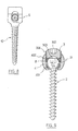
- a sacral attachment element generally designated by the reference 1, which consists of three parts, namely an upper eyelet 4, a sacred plate 5 and a rod 6, by cylindrical example, connecting the eyelet to the plate.
- Element 1 as a whole, in profile, has a lordose curvature illustrated in FIG. 1.
- the plate 5 In the plate 5 is formed a series of holes 7 aligned in the direction of the length of the element 1, for bone anchor screws 2.
- surgeon can be offered several models of elements 1, in particular with different lengths of rod 6, and in the plate 5, different numbers of holes for bone anchor screws.
- the plate 5 can receive, in a three-hole version 7, two screws 2 for bone anchoring and, in a five-hole version (not shown), three screws 2 for bone anchoring.
- the holes 7 communicate with each other by means of a through groove 9 of oblong section, as can be seen in FIG. 2.
- This groove makes it possible to easily pass a screw 2 from one position to another during the reduction operation.
- Each of these holes has, in the region of its bottom, a spherical cup 7a intended to cooperate with a complementary lower part of the head 21 of the screw 2, this head 21 being as a whole spherical and comprising a clamping imprint 211 by example of the hexagonal hexagon type.
- each hole 7 and of the associated screw head 21 allows an angular movement of the screw in a solid angle whose half-angle at the top is for example of the order of 30 °.
- each screw being stabilized in its housing during installation, two distant screws are suitable maintain bone distraction without requiring the use of a distracting instrument.
- each hole 7 has internally, at a distance from the cup 7a, a thread 8 allowing it to receive a plug 3 shown in detail in Figure 5.
- This plug has on its outer face a tightening imprint 302, preferably identical to that of the screw head 21 so that the same tightening tool can be used, and a housing in a spherical cup 301 cooperating with the equally spherical top of the screw head 21.
- the cap has also at its periphery a thread 304 intended to cooperate with the thread 8 of the orifice 7.
- the purpose of this plug 3, after screwing and tightening, is to secure the screw 2 in the angular position determined by the surgeon.
- the plate 5, the screw 2 and the plug 3 after assembly are illustrated in particular in FIG. 7.
- the threaded plug 3 provides a non-return function preventing any accidental unscrewing of the associated anchor screw 2, in particular under the conditions exposed in preamble to this application.
- the spondylolisthesis can be reduced by implanting in the pedicle of the vertebra concerned either an intermediate screw fixed on the intermediate connecting rod 6, or a screw placed in the eyelet 4.
- the intermediate rod 6 can thus be used to effect a vertebra return.
- a screw with higher loading generally designated by the reference 10 and known per se, which will have been previously implanted in the vertebra in question.
- the vertebra to be stressed can also be secured to the intermediate rod 6 using another type of device, not illustrated but also known per se, in which the screw is offset from the axis of the rod 6 but connected to the latter by a holding system.
- the upper eyelet 4 of the element 1 which is used to receive a bone anchoring screw 2 in the vertebra to be treated, this screw 2 preferably being of the same type as that described above. above.
- a hole 7 identical to that described with reference to the plate 5 is formed in said eyelet, to again allow angulation of the screw 2 and a non-return function allowing, thanks to a plug 3, to avoid that it does not loosen.
- This relative mobility of the screw 2 in the eyelet 4 can be ensured in different ways.
- a first solution consists in repeating the principle illustrated in FIG. 7 by using a threaded plug 3 and by providing in the hole 7 of the eyelet a shoulder preventing the plug 3 from reaching a screw locking position. 2 in angular position.
- such a shoulder can be formed on the threaded plug 3.
- the friction between the plug 3 and the head 21 of the screw 2 can be reduced to negligible by applying a coating with a low coefficient of friction, for example of ceramic or carbon diamond type, in a thin layer. on one or more of the different surfaces in contact, namely the screw head 21, the cup 7a of the hole 7 of the eyelet 4, and the cup 301 of the threaded plug 3.
- a coating with a low coefficient of friction for example of ceramic or carbon diamond type
- such a coating can be applied only to the head 21 of the screw 2.
- FIGS. 9 to 14 a number of alternative embodiments will be described which make it possible to attenuate the rigidity of the assembly of the screw 2 and of the eyelet 4 into which it is introduced, in order here again to avoid hinge syndrome.
- FIG. 9 describes a solution in which any contact between the rigid parts having to adopt relative movements is avoided by the use of a first O-ring 401, lower, and of a second O-ring 402, upper.
- These two rings are preferably made of a damping material such as silicone, and are illustrated in FIG. 9 in the deformed state after tightening.
- the surgeon is provided with rings having different shades of hardness, while retaining the same dimensions, which allows him to modulate the rigidity of the assembly without having to play on the tightening torque of the threaded plug 3, this which would prove to be very difficult to implement reliably.
- the plug 3 here again has a spherical cup 303, intended only to allow the angulation of the screw 2, but without blocking support on the head 21 of the said screw.
- FIG. 10 describes a variant in which the plug 31 differs from that of FIG. 5 in that its cup, indicated at 311, is no longer complementary to the spherical head 21 of the screw 2, but is flared, while 'A ball 411 of damping material is interposed between the cup 311 and said head 21, and pressurized and deformed during tightening.
- FIG. 11 describes a variant in which the threaded plug 32 has a flat working surface, and in which the direct contact between the plug 32 and the screw head 21 is eliminated by the use of an O-ring 412 produced in a cushioning material, pressurized and deformed during tightening.
- FIG. 12 describes a variant in which the plug, designated by the reference 33, has on its working face a conical recess 331, and in which the contact between the plug 33 and the screw head 21 is eliminated by injection, during the laying operation, a tyxotropic fluid 413 ensuring a damping function.
- the contact friction between the spherical head 21 and the cup 7a of the hole 7 formed in the eyelet 4 can also be reduced by the use of a coating.
- the coating used in the variant of FIG. 12 will be chosen so that the contact between the base of the spherical head 21 and the cup 7a seals the tyxotropic fluid pressurized during screwing.
- Figures 13 and 14 describe another alternative embodiment in which the eyelet is modified. More specifically, the eyelet 4 has a generally cylindrical cup 421, the part remote from the bottom is threaded at 8 to receive the threaded plug 3, identical to that of FIG. 5.
- a ring 422 is interposed between the bowl 421 and the screw head 21. It can be either a rigid ring, made for example of titanium alloy coated with a ceramic, or of titanium alloy treated by ion bombardment. , or else of solid ceramic, or again of an O-ring identical to the ring 401 used in the alternative embodiment of FIG. 9, produced again in a damping material, for example silicone.
- the radius of curvature of its internal spherical range may be advantageous to give the radius of curvature of its internal spherical range a value slightly less than the radius of the screw head 21, so as to ensure that said head is stressed. of screws when tightening.
- the version of FIGS. 13 and 14 can advantageously also be used when total blocking of the screw is desired.
- the ring 422 can be split, again with stressing of the head 21 and a possibility of blocking.
- the parts such as the element 1, the screws 2, the plugs 3 are made of any biocompatible material with suitable mechanical properties, such as a titanium alloy.
- the shape and the dimensions of the element 1 are chosen so as to allow them to resist torsional stresses thanks to the plane support generated between the base of the plate-shaped part 5 and the adjacent bone.
- This shape also makes it possible to limit the longitudinal translation movements on the intermediate screws.
- the stiffness mitigation means described above ensure such attenuation both in the sagittal plane and in the transverse plane.
- the invention makes it possible to propose an osteosynthesis system having a great modularity: thus, for example, different versions of the ring 422 can be proposed to the practitioner to manage the anterior contact zone (vertebra side), while the one of the damping means described above can be proposed with different degrees of rigidity to manage the damping in the rear part (plug side). In practice, it is thus possible to cover the whole range between the flexible connections and the rigid connections.
- stiffness reduction means described above can be used both at the level of the screw of the eyelet 4 and at the level of the screws of the plate 5.
Abstract
Description
- La présente invention a trait d'une façon générale à un dispositif de fixation, en particulier au sacrum, utilisable en ostéosynthèse du rachis.
- Il est courant de pratiquer des ostéosynthèses du rachis en utilisant des dispositifs de fixation prenant ancrage dans le sacrum. Il est ainsi possible de procéder, entre les différents étages fixés, à des mouvements de réduction qui peuvent être des contractions, des distractions ou encore des rappels de vertèbres ayant glissé vers l'avant du rachis. Cette dernière pathologie est connue sous le nom de "spondylolisthésis".
- Dans le cas d'une réduction de spondylolisthésis, une distraction est souvent pratiquée. Une réduction partielle est ainsi obtenue par la remise en tension des fibres de l'appareil ligamentaire et discal du patient. La réduction est complétée par l'utilisation du matériel selon la technique opératoire qui lui est associée. Cette opération est réalisée, sauf cas exceptionnel, de manière bilatérale. Dans toute la description qui suit, on s'attachera à décrire un des côtés du traitement.
- La plupart des plaques ou blocs de fixation au sacrum connus dans l'art antérieur présentent certains inconvénients. L'un de ces inconvénients réside en ce que l'orientation des vis d'ancrage osseux est imposée, ce qui donne au produit un manque de souplesse d'utilisation évident compte-tenu des variations de configuration du sacrum et de son voisinage d'un patient à l'autre.
- Un autre inconvénient des plaques ou blocs de fixation au sacrum connus réside dans le risque d'un dévissage des vis d'ancrage sous l'effet notamment des micro-mouvements relatifs se produisant entre les matériels et le sacrum. Il en résulte alors la faillite de la fixation sacrée.
- Par ailleurs, les ostéosynthèses du rachis sont réalisées grâce à des matériels permettant de fixer, de facon souvent très rigide, différentes unités fonctionnelles de la colonne vertébrale. Il en découle une variation brutale de la répartition des efforts, et donc des états de contraintes et de déformations résultants, au niveau des disques sus- et sous-jacents à la fixation. Cette modification entraîne à plus ou moins long terme des dégénérescences discales. Cette pathologie est connue sous le nom de "syndrome de charnière".
- On connaît par ailleurs du document EP-A-0 625 337 un dispositif selon le préambule de la revendication 1, qui permet de faire varier l'inclinaison des vis d'ancrage par rapport à un élément de liaison allongé, de même que l'espacement entre ces vis.
- Ce dispostif connu est toutefois désavantageux en ce que les moyens de liaison allongés sont constitués de plusieurs composants, à savoir un organe allongé en forme de cuvette et une pluralité de blocs de fixation répartis le long de l'organe allongé et recevant chacun une tête de vis et, en partie inférieure, la zone correspondante de l'organe allongé.
- Il en résulte que la manipulation et la pose de ce dispositif par le chirurgien sont extrêmement fastidieuses, avec en particulier la nécessité de faire glisser sur l'organe allongé une série de blocs de fixation, et de les y maintenir en position.
- La présente invention vise donc à pallier cet inconvénient.
- Elle propose à cet effet un dispositif de fixation osseuse tel que défini dans la revendication 1.
- Des aspects préférés, mais non limitatifs, du dispositif selon l'invention sont définis dans les revendications dépendantes.
- D'autres aspects, buts et avantages de la présente invention apparaîtront mieux à la lecture de la description détaillée suivante de formes de réalisation préférées de celle-ci, donnée à titre d'exemple et faite en référence aux dessins annexés, sur lesquels :
- la figure 1 est une vue en coupe longitudinale médiane d'un élément de fixation selon l'invention,
- la figure 2 est une vue de face de l'élément de la figure 1,
- la figure 3 est une vue de côté de l'élément ainsi que de trois vis d'ancrage osseux et de bouchons associés,
- la figure 4 est une vue de face de l'élément pourvu des vis et des bouchons,
- la figure 5 est une vue en élévation de côté d'un bouchon destiné à coopérer avec l'élément des figures 1 et 2 et avec une vis d'ancrage osseux,,
- la figure 6 est une vue en élévation de côté de la vis d'ancrage osseux,
- la figure 7 est une vue en coupe transversale de l'élément de fixation, d'une vis d'ancrage osseux et du bouchon associé, après montage,
- la figure 8 est une vue partiellement en élévation et partiellement en coupe d'une vis d'ancrage osseux auxiliaire destinée à coopérer avec une autre partie de l'élément de fixation des figures 1 et 2,
- les figures 9 à 12 sont des vues en coupe transversale analogues à la figure 7, de quatre variantes de réalisation de l'invention,
- la figure 13 est une vue en coupe transversale des différents composants d'une cinquième variante de réalisation de l'invention, et
- la figure 14 est une vue en coupe transversale de cette cinquième variante à l'état assemblé.
- On notera à titre préliminaire que, d'une figure à l'autre, des éléments ou parties identiques ou similaires sont désignés dans la mesure du possible par les mêmes signes de référence, et ne seront pas décrits à chaque fois.
- En référence maintenant aux figures 1 et 2, on a représenté un élément de fixation au sacrum, globalement désigné par la référence 1, qui se compose de trois parties, à savoir un oeillet supérieur 4, une plaque sacrée 5 et une tige 6, par exemple cylindrique, reliant l'oeillet à la plaque. L'élément 1 présente dans son ensemble, en profil, une courbure en lordose illustrée sur la figure 1.
- Dans la plaque 5 est formée une série de trous 7 alignés dans le sens de la longueur de l'élément 1, pour des vis d'ancrage osseux 2.
- De préférence, on peut proposer au chirurgien plusieurs modèles d'éléments 1, avec notamment différentes longueurs de tige 6, et dans la plaque 5, différents nombres de trous pour vis d'ancrage osseux.
- Comme le montre la figure 3, la plaque 5 peut recevoir, dans une version à trois trous 7, deux vis 2 d'ancrage osseux et, dans une version à cinq trous (non illustrée), trois vis 2 d'ancrage osseux.
- Les trous 7 communiquent entre eux par le biais d'une rainure traversante 9 de section oblongue, comme on peut le voir sur la figure 2. Cette rainure permet de faire passer aisément une vis 2 d'une position à une autre au cours de l'opération de réduction. Chacun de ces trous comporte, dans la région de son fond, une cupule sphérique 7a destinée à coopérer avec une partie inférieure complémentaire de la tête 21 de la vis 2, cette tête 21 étant dans son ensemble sphérique et comportant une empreinte de serrage 211 par exemple du type à six pans hexagonaux.
- Cette conformation de chaque trou 7 et de la tête de vis associée 21 permet un débattement angulaire de la vis dans un angle solide dont le demi-angle au sommet est par exemple de l'ordre de 30°.
- Par ailleurs, chaque vis étant stabilisée dans son logement au cours de la pose, deux vis distantes sont aptes à maintenir une distraction osseuse sans nécessiter l'utilisation d'un instrument distracteur.
- Comme le montrent en particulier les figures 1 et 7, chaque trou 7 possède intérieurement, à distance de la cupule 7a, un taraudage 8 lui permettant de recevoir un bouchon 3 représenté en détail sur la figure 5. Ce bouchon comporte sur sa face extérieure une empreinte de serrage 302, de préférence identique à celle de la tête de vis 21 de manière à pouvoir utiliser le même outil de serrage, et un logement en cupule sphérique 301 coopérant avec le sommet également sphérique de la tête de vis 21. Le bouchon comporte également à sa périphérie un filetage 304 destiné à coopérer avec le filetage 8 de l'orifice 7. Ce bouchon 3 a pour objet, après vissage et serrage, d'assurer le blocage de la vis 2 dans la position angulaire déterminée par le chirurgien.
- La plaque 5, la vis 2 et le bouchon 3 après assemblage sont illustrés notamment sur la figure 7. Le bouchon fileté 3 assure une fonction anti-retour empêchant tout dévissage accidentel de la vis d'ancrage 2 associée, notamment dans les conditions exposés en préambule de la présente demande.
- En outre, grâce au dispositif de la présente invention, le spondylolisthésis peut être réduit en implantant dans le pédicule de la vertèbre concernée soit une vis intermédiaire fixée sur la tige de liaison intermédiaire 6, soit une vis placée dans l'oeillet 4.
- Dans le premier cas, la tige intermédiaire 6 peut ainsi être utilisée pour effectuer un rappel de vertèbre. A cet effet, et comme le montre la figure 8, on peut y associer une vis à chargement supérieur, globalement désignée par la référence 10 et connue en soi, qui aura été préalablement implantée dans la vertèbre en question.
- On peut également solidariser la vertèbre à solliciter à la tige intermédiaire 6 à l'aide d'un autre type de dispositif, non illustré mais également connu en soi, dans lequel la vis est décalée par rapport à l'axe de la tige 6 mais reliée à cette dernière par un svstème de maintien.
- Dans le second cas, c'est l'oeillet supérieur 4 de l'élément 1 qui est utilisé pour recevoir une vis d'ancrage osseux 2 dans la vertèbre à traiter, cette vis 2 étant de préférence de même type que celle décrite ci-dessus. A cet effet, un trou 7 identique à celui décrit en référence à la plaque 5 est formé dans ledit oeillet, pour permettre là encore une angulation de la vis 2 et une fonction anti-retour permettant grâce à un bouchon 3 d'éviter qu'elle ne se desserre.
- Afin de ne pas entraîner le syndrome de charnière décrit en préambule, on peut éviter d'assurer un strict blocage de la vis 2 introduite dans l'oeillet supérieur 4. On conserve alors dans ce cas une mobilité relative de la vis 2 par rapport à l'oeillet 4.
- De cette manière, la position de la vertèbre dans laquelle est ancrée la vis 2 introduite dans l'oeillet 4 est fixée, mais la fonctionnalité du disque intervertébral sous-jacent est en partie maintenue. On crée ainsi un gradient de rigidité dans la fixation qui a pour effet d'atténuer le brusque changement d'état de contraintes au niveau du disque sus-jacent.
- Cette mobilité relative de la vis 2 dans l'oeillet 4 peut être assurée de différentes manières.
- Une première solution, non illustrée, consiste à reprendre le principe illustré sur la figure 7 en utilisant un bouchon fileté 3 et en prévoyant dans le trou 7 de l'oeillet un épaulement empêchant le bouchon 3 d'atteindre une position de blocage de la vis 2 en position angulaire.
- En variante, également non illustrée, un tel épaulement peut être formé sur le bouchon fileté 3.
- En outre, ou alternativement, on peut diminuer jusqu'à rendre négligeable le frottement entre le bouchon 3 et la tête 21 de la vis 2 en appliquant en couche mince un revêtement à faible coefficient de friction, par exemple de type céramique ou carbone diamant, sur une ou plusieurs des différentes surfaces en contact, à savoir la tête de vis 21, la cupule 7a du trou 7 de l'oeillet 4, et la cupule 301 du bouchon fileté 3.
- Par exemple, on peut appliquer un tel revêtement seulement sur la tête 21 de la vis 2.
- Maintenant en référence aux figures 9 à 14, on va décrire un certain nombre de variantes de réalisation permettant d'atténuer la rigidité de l'assemblage de la vis 2 et de l'oeillet 4 dans lequel elle est introduite, afin là encore d'éviter le syndrome de charnière.
- Ainsi la figure 9 décrit une solution dans laquelle tout contact entre les pièces rigides devant adopter des mouvements relatifs est évité par l'utilisation d'une première bague torique 401, inférieure, et d'une seconde bague torique 402, supérieure. Ces deux bagues sont de préférence réalisées en un matériau amortissant tel que du silicone, et sont illustrées sur la figure 9 à l'état déformé après serrage.
- Ainsi, lorsque les bagues 401, 402 sont mises en pression et déformées lors du serrage, elles assurent une liaison à rigidité atténuée entre la vis 2 et l'oeillet 4.
- Avantageusement, on met à disposition du chirurgien des bagues possédant différentes nuances de dureté, tout en conservant les mêmes dimensions, ce qui lui permet de moduler la rigidité de l'assemblage sans avoir à jouer sur le couple de serrage du bouchon fileté 3, ce qui s'avèrerait très délicat à mettre en oeuvre de façon fiable.
- En outre, pour minimiser les frottements entre les bagues 401, 402 et la tête 21 de la vis, il peut être avantageux de réaliser sur la vis un traitement de surface par bombardement ionique à l'azote, qui permet d'améliorer les caractéristiques tribologiques de la tête de vis.
- Toujours en référence à la figure 9, on observe que le bouchon 3 possède ici encore une cupule sphérique 303, destinée seulement à permettre l'angulation de la vis 2, mais sans appui bloquant sur la tête 21 de ladite vis.
- La figure 10 décrit une variante dans laquelle le bouchon 31 se distingue de celui de la figure 5 en ce que sa cupule, indiquée en 311, n'est plus complémentaire de la tête sphérique 21 de la vis 2, mais est évasée, tandis qu'une bille 411 en matériau amortissant est interposée entre la cupule 311 et ladite tête 21, et mise en pression et déformée lors du serrage.
- On assure ici encore une atténuation de la rigidité d'assemblage.
- La figure 11 décrit une variante dans laquelle le bouchon fileté 32 présente une surface de travail plane, et dans laquelle le contact direct entre le bouchon 32 et la tête de vis 21 est supprimé par l'utilisation d'une bague torique 412 réalisée dans un matériau amortissant, mise en pression et déformée lors du serrage.
- La figure 12 décrit une variante dans laquelle le bouchon, désigné par la référence 33, présente sur sa face de travail un renfoncement conique 331, et dans laquelle le contact entre le bouchon 33 et la tête de vis 21 est supprimé par l'injection, au cours de l'opération de pose, d'un fluide tyxotropique 413 assurant une fonction d'amortissement.
- En outre, dans les trois variantes de réalisation des figures 10, 11 et 12 le frottement de contact entre la tête sphérique 21 et la cupule 7a du trou 7 formé dans l'oeillet 4 peut également être réduit par l'utilisation d'un revêtement tel que cité plus haut. A cet égard, le revêtement utilisé dans la variante de la figure 12 sera choisi de manière à ce que le contact entre la base de la tête sphérique 21 et la cupule 7a assure l'étanchéité du fluide tyxotropique mis sous pression lors du vissage.
- Les figures 13 et 14 décrivent une autre variante de réalisation dans laquelle l'oeillet est modifié. Plus précisément, l'oeillet 4 présente une cuvette généralement cylindrique 421 dont la partie éloignée du fond est filetée en 8 pour recevoir le bouchon fileté 3, identique à celui de la figure 5.
- Entre la cuvette 421 et la tête de vis 21 est interposé un anneau 422. Il peut s'agir soit d'un anneau rigide, réalisé par exemple en alliage de titane revêtu d'une céramique, ou en alliage de titane traité par bombardement ionique, ou encore de céramique massive, soit encore d'une bague torique identique à la bague 401 utilisée dans la variante de réalisation de la figure 9, réalisée là encore en un matériau amortissant, par exemple du silicone.
- Dans le cas où l'anneau 422 est rigide, il peut être avantageux de donner au rayon de courbure de sa portée sphérique intérieure une valeur légèrement inférieure au rayon de la tête de vis 21, de manière à assurer une mise en contrainte de ladite tête de vis lors du serrage. Dans ce cas, la version des figures 13 et 14 peut avantageusement être utilisée également lorsqu'un blocage total de la vis est souhaité.
- Selon une autre variante, l'anneau 422 peut être fendu, avec là encore une mise en contrainte de la tête 21 et une possibilité de blocage.
- Naturellement, les pièces tels que l'élément 1, les vis 2, les bouchons 3 sont réalisées en tout matériau biocompatible de propriétés mécaniques adaptées, tel qu'un alliage de titane.
- On donnera ci-dessous pour terminer quelques observations complémentaires.
- Tout d'abord la forme et les dimensions de l'élément 1 sont choisies de façon à permettre de résister aux contraintes de torsion grâce à l'appui plan engendré entre la base de la partie 5 en forme de plaque et l'os adjacent.
- Cette forme permet également de limiter les mouvements de translation longitudinqale sur les vis intermédiaires.
- Ensuite, les moyens d'atténuation de la rigidté décrits plus haut assurent une telle atténuation à la fois dans le plan sagittal et dans le plan transversal.
- Enfin l'invention permet de proposer un système d'ostéosynthèse présentant une grande modularité : ainsi, par exemple, différentes versions de l'anneau 422 peuvent être proposées au praticien pour gérer la zone de contact antérieure (côté vertèbre), tandis que l'un des moyens d'amortissement décrits plus haut peut être proposé avec différents degrés de rigidité pour gérer l'amortissement en partie postérieure (côté bouchon). Dans la pratique, on peut ainsi couvrir toute la gamme entre les liaisons souples et les liaisons rigides.
- A cet égard, on observera que les moyens d'atténuation de rigidité décrits plus haut peuvent être utilisés aussi bien au niveau de la vis de l'oeillet 4 qu'au niveau des vis de la plaque 5.
- Bien entendu, la présente invention n'est nullement limitée aux formes de réalisation décrites et représentées, mais l'homme du métier saura y apporter toute variante ou modification conforme à son esprit.
Claims (19)
- Dispositif de fixation osseuse, notamment au sacrum pour ostéosynthèse du rachis, comprenant des moyens de liaison allongés recevant au moins une vis (2) d'ancrage dans un os, vis qui traverse un orifice (7) formé les moyens de liaison, dans lequel les moyens de liaison comportent dans la région de leur fond une portée de section transversale essentiellement circulaire (7a), dans lequel la tête (21) de la vis comporte une surface essentiellement sphérique d'appui contre ladite portée, et dans lequel les moyens de liaison comportent au niveau de l'orifice un premier filetage (8), le dispositif comprenant en outre un bouchon (3) comportant un second filetage (304) apte à coopérer avec le premier filetage et à venir en contact de serrage avec ladite tête de vis (21) pour la maintenir dans une position angulaire souhaitée, dispositif caractérisé en ce que les moyens de liaison sont constitués par un élément en forme de plaque d'un seul tenant (5) dans laquelle sont ménagés l'orifice (7) et le premier filetage (8), et en ce que ladite portée (7a) est essentiellement sphérique.
- Dispositif selon la revendication 1, caractérisé en ce que le premier filetage est un taraudage (8) formé intérieurement dans l'orifice à distance dudit fond, et en ce que le bouchon (3) est fileté extérieurement (304).
- Dispositif selon l'une des revendications 1 et 2, caractérisé en ce que la tête de vis (21) présente en outre un sommet généralement sphérique, et en ce que le bouchon (3) comporte intérieurement une cavité sphérique (301) complémentaire.
- Dispositif selon la revendication 1 ou 2, caractérisé en ce que ladite plaque (5) comporte une série d'orifices (7) alignés et reliés entre eux par une rainure (9) permettant le déplacement d'une vis d'ancrage osseux (2) d'un orifice à l'autre avant serrage.
- Dispositif selon l'une des revendications 1 à 4, caractérisé en ce que ladite tête de vis (21) et ledit bouchon (3) comportent des empreintes de serrage identiques (211, 302).
- Dispositif selon l'une des revendications 1 à 5, caractérisé en ce que ladite plaque (5) est destinée à une fixation dans un premier os et fait partie d'un élément d'un seul tenant (1) comportant en outre un oeillet (4) pour une autre vis (2) d'ancrage osseux dans un second os, et une tige (6) reliant ladite plaque audit oeillet.
- Dispositif selon la revendication 6, caractérisé en ce qu'il comprend en outre un dispositif (10) d'ancrage osseux dans un autre os, sur lequel est fixée ladite tige (6).
- Dispositif selon l'une des revendications 1 à 7, caractérisé en ce qu'il comprend au moins deux vis (2) d'ancrage osseux traversant des orifices respectifs (7) formés dans ladite plaque (5), et en ce que les deux vis sont aptes à prendre deux positions angulaires différentes.
- Dispositif selon l'une des revendications 1 à 8, caractérisé en ce qu'il comprend en outre des moyens (401, 402; 411; 412; 413; 422) pour atténuer la rigidité de l'assemblage entre au moins l'une des vis (2) d'ancrage et ledit élément (1).
- Dispositif selon la revendication 9, caractérisé en ce que lesdits moyens d'atténuation de la rigidité comprennent au moins une pièce en matériau souple (402; 411; 412) interposée et comprimée entre ladite tête de vis (21) et le bouchon associé (3).
- Dispositif selon la revendication 10, caractérisé en ce qu'y est associée une pluralité de pièces en matériau souple de souplesses différentes, de manière à permettre différents degrés d'atténuation de la rigidité sans avoir à jouer sur le couple de serrage du bouchon (3).
- Dispositif selon la revendication 10 ou 11, caractérisé en ce que ladite pièce est une bague torique (402, 412).
- Dispositif selon la revendication 10 ou 11, caractérisé en ce que ladite pièce est une bille torique (411).
- Dispositif selon la revendication 9, caractérisé en ce que lesdits moyens d'atténuation de la rigidité comprennent un fluide tyxotropique (413) interposé et mis sous pression entre le bouchon (3) et ladite tête de vis (21).
- Dispositif selon l'une des revendications 1 à 14, caractérisé en ce que ladite portée sphérique dudit orifice est formée par déformation d'une bague torique (401) placée dans une région de fond dudit orifice (7).
- Dispositif selon l'une des revendications 1 à 14, caractérisé en ce que ladite portée sphérique dudit orifice est constituée par une surface d'une bague rigide (422) rapportée dans une région de fond dudit orifice (7).
- Dispositif selon la revendication 16, caractérisé en ce que ladite bague rigide (422) est réalisée en un matériau choisi dans le groupe comprenant les alliages de titane revêtus de céramique, les alliages de titane traités par bombardement ionique, et les céramiques massives.
- Dispositif selon l'une des revendications 9 à 14, caractérisé en ce que les moyens d'atténuation de la rigidité comprennent en outre un revêtement de surface apte à diminuer les frottements entre ladite portée essentiellement sphérique (7a) et ladite surface complémentaire de la tête de vis (21).
- Dispositif selon la revendication 18, caractérisé en ce que ledit revêtement de surface est réalisé par bombardement ionique à l'azote.
Applications Claiming Priority (2)
| Application Number | Priority Date | Filing Date | Title |
|---|---|---|---|
| FR9605898A FR2748387B1 (fr) | 1996-05-13 | 1996-05-13 | Dispositif de fixation osseuse, en particulier au sacrum, en osteosynthese du rachis |
| FR9605898 | 1996-05-13 |
Publications (2)
| Publication Number | Publication Date |
|---|---|
| EP0807420A1 true EP0807420A1 (fr) | 1997-11-19 |
| EP0807420B1 EP0807420B1 (fr) | 2002-07-31 |
Family
ID=9492057
Family Applications (1)
| Application Number | Title | Priority Date | Filing Date |
|---|---|---|---|
| EP97401057A Expired - Lifetime EP0807420B1 (fr) | 1996-05-13 | 1997-05-13 | Dispositif de fixation osseuse, en particulier au sacrum, en ostéosynthèse du rachis |
Country Status (13)
| Country | Link |
|---|---|
| US (2) | US6022350A (fr) |
| EP (1) | EP0807420B1 (fr) |
| JP (1) | JP4017211B2 (fr) |
| KR (1) | KR970073530A (fr) |
| AT (1) | ATE221342T1 (fr) |
| AU (1) | AU733342B2 (fr) |
| CA (1) | CA2206152C (fr) |
| DE (2) | DE807420T1 (fr) |
| DK (1) | DK0807420T3 (fr) |
| ES (1) | ES2121569T3 (fr) |
| FR (1) | FR2748387B1 (fr) |
| NO (1) | NO972166D0 (fr) |
| NZ (1) | NZ314798A (fr) |
Cited By (11)
| Publication number | Priority date | Publication date | Assignee | Title |
|---|---|---|---|---|
| EP0988833A3 (fr) * | 1998-09-24 | 2000-04-12 | Sulzer Orthopedics Ltd. | Plaque d'ostéosynthèse avec plusieurs vis à os |
| WO2000062704A1 (fr) * | 1999-04-15 | 2000-10-26 | Nobel Biocare Ab | Vis de fixation dentaire revetue d'un depot cda |
| EP1759647A1 (fr) * | 2000-08-08 | 2007-03-07 | DePuy Spine, Inc. | Tige vertébrale/ mécanisme de verrouillage d'une plaque |
| EP1847229A2 (fr) * | 1997-02-11 | 2007-10-24 | Warsaw Orthopedic, Inc. | Système de plaquage squelettique à verrou unique |
| FR2912895A1 (fr) * | 2007-02-28 | 2008-08-29 | Small Bone Innovations Interna | Materiel d'arthodese |
| WO2008098728A3 (fr) * | 2007-02-12 | 2008-10-23 | Stryker Trauma Gmbh | Dispositif de fixation |
| WO2009081346A1 (fr) * | 2007-12-19 | 2009-07-02 | Istituto Ortopedico Rizzoli | Prothèse acétabulaire |
| WO2010045453A1 (fr) * | 2008-10-17 | 2010-04-22 | Warsaw Orthopedic, Inc. | Ensemble ancre dynamique permettant de raccorder des éléments dans des procédures chirurgicales rachidiennes |
| ITTO20120168A1 (it) * | 2012-02-24 | 2013-08-25 | Medicomp S R L | Sistema di fissaggio multi-assiale per osteosintesi |
| US9974571B2 (en) | 2008-09-12 | 2018-05-22 | DePuy Synthes Products, Inc. | Spinal stabilizing and guiding fixation system |
| US10405892B2 (en) | 2008-11-03 | 2019-09-10 | DePuy Synthes Products, Inc. | Uni-planer bone fixation assembly |
Families Citing this family (458)
| Publication number | Priority date | Publication date | Assignee | Title |
|---|---|---|---|---|
| FR2748387B1 (fr) * | 1996-05-13 | 1998-10-30 | Stryker France Sa | Dispositif de fixation osseuse, en particulier au sacrum, en osteosynthese du rachis |
| US6139550A (en) * | 1997-02-11 | 2000-10-31 | Michelson; Gary K. | Skeletal plating system |
| ES2268267T3 (es) * | 1997-02-11 | 2007-03-16 | Warsaw Orthopedic, Inc. | Placa cervical anterior para dispositivo de bloqueo de tipo unico. |
| ZA983955B (en) | 1997-05-15 | 2001-08-13 | Sdgi Holdings Inc | Anterior cervical plating system. |
| IES77331B2 (en) * | 1997-06-03 | 1997-12-03 | Tecos Holdings Inc | Pluridirectional and modulable vertebral osteosynthesis device of small overall size |
| US6258089B1 (en) * | 1998-05-19 | 2001-07-10 | Alphatec Manufacturing, Inc. | Anterior cervical plate and fixation system |
| DE69937461T2 (de) | 1998-11-12 | 2008-08-21 | Nobel Biocare Ab | Mit diamantähnlichem kohlenstoff überzogenes zahnärztliches instrument |
| US6585769B1 (en) | 1999-04-05 | 2003-07-01 | Howmedica Osteonics Corp. | Artificial spinal ligament |
| AU1493301A (en) | 1999-09-27 | 2001-04-30 | Blackstone Medical, Inc. | A surgical screw system and related methods |
| US6811567B2 (en) * | 1999-10-22 | 2004-11-02 | Archus Orthopedics Inc. | Facet arthroplasty devices and methods |
| US6974478B2 (en) * | 1999-10-22 | 2005-12-13 | Archus Orthopedics, Inc. | Prostheses, systems and methods for replacement of natural facet joints with artificial facet joint surfaces |
| EP1854433B1 (fr) * | 1999-10-22 | 2010-05-12 | FSI Acquisition Sub, LLC | Dispositifs d'arthroplastie facettaire |
| US8187303B2 (en) | 2004-04-22 | 2012-05-29 | Gmedelaware 2 Llc | Anti-rotation fixation element for spinal prostheses |
| US7674293B2 (en) * | 2004-04-22 | 2010-03-09 | Facet Solutions, Inc. | Crossbar spinal prosthesis having a modular design and related implantation methods |
| US7691145B2 (en) * | 1999-10-22 | 2010-04-06 | Facet Solutions, Inc. | Prostheses, systems and methods for replacement of natural facet joints with artificial facet joint surfaces |
| US6702821B2 (en) | 2000-01-14 | 2004-03-09 | The Bonutti 2003 Trust A | Instrumentation for minimally invasive joint replacement and methods for using same |
| US6770078B2 (en) | 2000-01-14 | 2004-08-03 | Peter M. Bonutti | Movable knee implant and methods therefor |
| US7635390B1 (en) * | 2000-01-14 | 2009-12-22 | Marctec, Llc | Joint replacement component having a modular articulating surface |
| US6440135B2 (en) | 2000-02-01 | 2002-08-27 | Hand Innovations, Inc. | Volar fixation system with articulating stabilization pegs |
| US20040153073A1 (en) * | 2000-02-01 | 2004-08-05 | Hand Innovations, Inc. | Orthopedic fixation system including plate element with threaded holes having divergent axes |
| US6893444B2 (en) * | 2000-02-01 | 2005-05-17 | Hand Innovations, Llc | Bone fracture fixation systems with both multidirectional and unidirectional stabilization pegs |
| US6712820B2 (en) | 2000-02-01 | 2004-03-30 | Hand Innovations, Inc. | Fixation plate system for dorsal wrist fracture fixation |
| US6706046B2 (en) * | 2000-02-01 | 2004-03-16 | Hand Innovations, Inc. | Intramedullary fixation device for metaphyseal long bone fractures and methods of using the same |
| US20060041260A1 (en) * | 2000-02-01 | 2006-02-23 | Orbay Jorge L | Fixation system with plate having holes with divergent axes and multidirectional fixators for use therethrough |
| US6767351B2 (en) * | 2000-02-01 | 2004-07-27 | Hand Innovations, Inc. | Fixation system with multidirectional stabilization pegs |
| US7857838B2 (en) * | 2003-03-27 | 2010-12-28 | Depuy Products, Inc. | Anatomical distal radius fracture fixation plate |
| US7695502B2 (en) | 2000-02-01 | 2010-04-13 | Depuy Products, Inc. | Bone stabilization system including plate having fixed-angle holes together with unidirectional locking screws and surgeon-directed locking screws |
| US6610062B2 (en) | 2000-02-16 | 2003-08-26 | Ebi, L.P. | Method and system for spinal fixation |
| DE20006772U1 (de) * | 2000-04-12 | 2001-08-23 | Meritor Automotive Gmbh | Verbindungselement, insbesondere eine Schraube zur Befestigung eines Dichtungsprofils an einem Karosserieteil |
| US6235033B1 (en) | 2000-04-19 | 2001-05-22 | Synthes (Usa) | Bone fixation assembly |
| DE60138544D1 (de) | 2000-05-11 | 2009-06-10 | Nobel Biocare Ab | PSEUDO-ÄTZUNG VON einem MIT DIAMANTÄHNLICHEM KOHLENSTOFF ÜBERZOGENEN dentalen Osteotom |
| EP1153577B9 (fr) * | 2000-05-12 | 2008-07-23 | Zimmer GmbH | Fixation contenant une vis et une plaque d'ostéosynthèse |
| JP2002000611A (ja) * | 2000-05-12 | 2002-01-08 | Sulzer Orthopedics Ltd | 骨ネジの骨板への結合 |
| CA2413474A1 (fr) * | 2000-06-30 | 2002-01-03 | Henry Graf | Dispositif de liaison intervertebral |
| US7833250B2 (en) | 2004-11-10 | 2010-11-16 | Jackson Roger P | Polyaxial bone screw with helically wound capture connection |
| US20080177310A1 (en) * | 2000-10-20 | 2008-07-24 | Archus Orthopedics, Inc. | Facet arthroplasty devices and methods |
| US6740088B1 (en) * | 2000-10-25 | 2004-05-25 | Sdgi Holdings, Inc. | Anterior lumbar plate and method |
| US6726689B2 (en) * | 2002-09-06 | 2004-04-27 | Roger P. Jackson | Helical interlocking mating guide and advancement structure |
| US8377100B2 (en) * | 2000-12-08 | 2013-02-19 | Roger P. Jackson | Closure for open-headed medical implant |
| US6413259B1 (en) | 2000-12-14 | 2002-07-02 | Blackstone Medical, Inc | Bone plate assembly including a screw retaining member |
| FR2819169A1 (fr) * | 2001-01-09 | 2002-07-12 | Brice Edouard | Dispositif d'osteosynthese pour colonne vertebrale |
| US6869433B2 (en) | 2001-01-12 | 2005-03-22 | Depuy Acromed, Inc. | Polyaxial screw with improved locking |
| FR2823096B1 (fr) * | 2001-04-06 | 2004-03-19 | Materiel Orthopedique En Abreg | Plaque pour dispositif d'osteosynthese des vertebres l5 et s1, dispositif d'osteosynthese incluant une telle plaque, et instrument pour la pose d'une telle plaque |
| US7578825B2 (en) * | 2004-04-19 | 2009-08-25 | Acumed Llc | Placement of fasteners into bone |
| US20050234458A1 (en) * | 2004-04-19 | 2005-10-20 | Huebner Randall J | Expanded stabilization of bones |
| US20070055249A1 (en) * | 2003-06-20 | 2007-03-08 | Jensen David G | Bone plates with intraoperatively tapped apertures |
| US20050240187A1 (en) * | 2004-04-22 | 2005-10-27 | Huebner Randall J | Expanded fixation of bones |
| US7717945B2 (en) * | 2002-07-22 | 2010-05-18 | Acumed Llc | Orthopedic systems |
| US10258382B2 (en) * | 2007-01-18 | 2019-04-16 | Roger P. Jackson | Rod-cord dynamic connection assemblies with slidable bone anchor attachment members along the cord |
| US7862587B2 (en) | 2004-02-27 | 2011-01-04 | Jackson Roger P | Dynamic stabilization assemblies, tool set and method |
| US8292926B2 (en) | 2005-09-30 | 2012-10-23 | Jackson Roger P | Dynamic stabilization connecting member with elastic core and outer sleeve |
| US8353932B2 (en) | 2005-09-30 | 2013-01-15 | Jackson Roger P | Polyaxial bone anchor assembly with one-piece closure, pressure insert and plastic elongate member |
| US10729469B2 (en) | 2006-01-09 | 2020-08-04 | Roger P. Jackson | Flexible spinal stabilization assembly with spacer having off-axis core member |
| US6746451B2 (en) * | 2001-06-01 | 2004-06-08 | Lance M. Middleton | Tissue cavitation device and method |
| EP1404243A4 (fr) * | 2001-06-04 | 2010-05-19 | Warsaw Orthopedic Inc | Systeme de plaque cervicale anterieure dynamique compose de segments mobiles, appareillage et procede de pose associes |
| US7186256B2 (en) * | 2001-06-04 | 2007-03-06 | Warsaw Orthopedic, Inc. | Dynamic, modular, single-lock anterior cervical plate system having assembleable and movable segments |
| JP4286130B2 (ja) | 2001-06-04 | 2009-06-24 | ウォーソー・オーソペディック・インコーポレーテッド | 椎体係合固定具および接続平板を有する前頚部平板システム、およびその据付方法 |
| US7097645B2 (en) * | 2001-06-04 | 2006-08-29 | Sdgi Holdings, Inc. | Dynamic single-lock anterior cervical plate system having non-detachably fastened and moveable segments |
| US7041105B2 (en) * | 2001-06-06 | 2006-05-09 | Sdgi Holdings, Inc. | Dynamic, modular, multilock anterior cervical plate system having detachably fastened assembleable and moveable segments |
| US7044952B2 (en) * | 2001-06-06 | 2006-05-16 | Sdgi Holdings, Inc. | Dynamic multilock anterior cervical plate system having non-detachably fastened and moveable segments |
| FR2826861B1 (fr) * | 2001-07-04 | 2004-06-18 | Materiel Orthopedique En Abreg | Connecteur lateral a decalage ajustable pour dispositif de correction et de stabilisation du rachis, organe de fixation adapte a ce connecteur et ensemble forme par ce connecteur et cet organe de fixation |
| FR2827499B1 (fr) * | 2001-07-20 | 2004-05-07 | Henry Graf | Dispositif de liaison intervertebral |
| US7708741B1 (en) | 2001-08-28 | 2010-05-04 | Marctec, Llc | Method of preparing bones for knee replacement surgery |
| US7198627B2 (en) * | 2001-09-07 | 2007-04-03 | Zimmer Spine, Inc. | Spinal fixation device and method |
| FR2830742B1 (fr) * | 2001-10-17 | 2004-07-30 | Spinevision Sa | Systeme pour maintenir au moins deux vertebres l'une par rapport a l'autre pour realiser une osteosynthese rachidienne |
| US6887242B2 (en) * | 2001-10-17 | 2005-05-03 | Ortho Innovations, Llc | Split ring bone screw for a spinal fixation system |
| US6623485B2 (en) * | 2001-10-17 | 2003-09-23 | Hammill Manufacturing Company | Split ring bone screw for a spinal fixation system |
| DE10152094C2 (de) * | 2001-10-23 | 2003-11-27 | Biedermann Motech Gmbh | Fixationseinrichtung für Knochen |
| SE522202C2 (sv) * | 2001-10-29 | 2004-01-20 | Gen Orthopedics Internat Ab | System för fixering av frakturer |
| US6679883B2 (en) | 2001-10-31 | 2004-01-20 | Ortho Development Corporation | Cervical plate for stabilizing the human spine |
| US7766947B2 (en) * | 2001-10-31 | 2010-08-03 | Ortho Development Corporation | Cervical plate for stabilizing the human spine |
| US6755833B1 (en) | 2001-12-14 | 2004-06-29 | Kamaljit S. Paul | Bone support assembly |
| US7070599B2 (en) * | 2002-07-24 | 2006-07-04 | Paul Kamaljit S | Bone support assembly |
| US7713272B2 (en) * | 2001-12-20 | 2010-05-11 | Ethicon, Inc. | Bioabsorbable coatings of surgical devices |
| CN1271976C (zh) * | 2001-12-24 | 2006-08-30 | 库尔斯恩蒂斯股份公司 | 用于骨接合的装置 |
| FR2835733B1 (fr) * | 2002-02-11 | 2004-04-23 | Thierry Begue | Patte pour fixer au moins deux portions d'os l'une par rapport a l'autre |
| US7322983B2 (en) * | 2002-02-12 | 2008-01-29 | Ebi, L.P. | Self-locking bone screw and implant |
| US7066937B2 (en) * | 2002-02-13 | 2006-06-27 | Endius Incorporated | Apparatus for connecting a longitudinal member to a bone portion |
| US7879075B2 (en) | 2002-02-13 | 2011-02-01 | Zimmer Spine, Inc. | Methods for connecting a longitudinal member to a bone portion |
| US6695846B2 (en) * | 2002-03-12 | 2004-02-24 | Spinal Innovations, Llc | Bone plate and screw retaining mechanism |
| US20040116930A1 (en) * | 2002-06-10 | 2004-06-17 | O'driscoll Shawn W. | Bone plates |
| US6793678B2 (en) | 2002-06-27 | 2004-09-21 | Depuy Acromed, Inc. | Prosthetic intervertebral motion disc having dampening |
| US7001389B1 (en) | 2002-07-05 | 2006-02-21 | Navarro Richard R | Fixed and variable locking fixation assembly |
| ES2277087T3 (es) * | 2002-07-09 | 2007-07-01 | Aecc Enterprises Limited | Metodo para representacion con imagenes el movimiento relativo de segmentos esqueleticos. |
| US6989012B2 (en) * | 2002-07-16 | 2006-01-24 | Sdgi Holdings, Inc. | Plating system for stabilizing a bony segment |
| US20050171544A1 (en) * | 2004-02-02 | 2005-08-04 | Acumed Llc | Bone plate with toothed aperture |
| US7179260B2 (en) * | 2003-09-29 | 2007-02-20 | Smith & Nephew, Inc. | Bone plates and bone plate assemblies |
| US8523913B2 (en) | 2002-09-06 | 2013-09-03 | Roger P. Jackson | Helical guide and advancement flange with break-off extensions |
| US20060009773A1 (en) * | 2002-09-06 | 2006-01-12 | Jackson Roger P | Helical interlocking mating guide and advancement structure |
| US8257402B2 (en) * | 2002-09-06 | 2012-09-04 | Jackson Roger P | Closure for rod receiving orthopedic implant having left handed thread removal |
| US8876868B2 (en) | 2002-09-06 | 2014-11-04 | Roger P. Jackson | Helical guide and advancement flange with radially loaded lip |
| US8282673B2 (en) * | 2002-09-06 | 2012-10-09 | Jackson Roger P | Anti-splay medical implant closure with multi-surface removal aperture |
| US20040111090A1 (en) * | 2002-10-03 | 2004-06-10 | The University Of North Carolina At Chapel Hill | Modification of percutaneous intrafocal plate system |
| FR2845587B1 (fr) * | 2002-10-14 | 2005-01-21 | Scient X | Dispositif dynamique de liaison intervertebrale a debattement controle multidirectionnel |
| CN101056591A (zh) * | 2002-10-28 | 2007-10-17 | 黑石医药股份有限公司 | 设置有螺钉锁定结构的骨板组件 |
| US7682392B2 (en) | 2002-10-30 | 2010-03-23 | Depuy Spine, Inc. | Regenerative implants for stabilizing the spine and devices for attachment of said implants |
| GB2412875A (en) * | 2002-11-19 | 2005-10-12 | Acumed Llc | Deformable bone plates |
| AU2003294342A1 (en) * | 2002-11-19 | 2004-06-15 | Acumed Llc | Guide system for bone-repair devices |
| AU2003295749B2 (en) * | 2002-11-19 | 2007-12-06 | Acumed Llc | Adjustable bone plates |
| US20050187551A1 (en) * | 2002-12-02 | 2005-08-25 | Orbay Jorge L. | Bone plate system with bone screws fixed by secondary compression |
| EP1567073B1 (fr) | 2002-12-06 | 2014-04-02 | Synthes GmbH | Dispositif pour stabiliser des os |
| US7780664B2 (en) * | 2002-12-10 | 2010-08-24 | Depuy Products, Inc. | Endosteal nail |
| US7104992B2 (en) * | 2003-01-14 | 2006-09-12 | Ebi, L.P. | Spinal fixation system |
| US8551100B2 (en) | 2003-01-15 | 2013-10-08 | Biomet Manufacturing, Llc | Instrumentation for knee resection |
| US7789885B2 (en) * | 2003-01-15 | 2010-09-07 | Biomet Manufacturing Corp. | Instrumentation for knee resection |
| US7837690B2 (en) * | 2003-01-15 | 2010-11-23 | Biomet Manufacturing Corp. | Method and apparatus for less invasive knee resection |
| US7887542B2 (en) * | 2003-01-15 | 2011-02-15 | Biomet Manufacturing Corp. | Method and apparatus for less invasive knee resection |
| US7575588B2 (en) * | 2003-02-03 | 2009-08-18 | Warsaw Orthopedic Inc. | Midline occipital vertebral fixation system |
| WO2004071276A2 (fr) | 2003-02-05 | 2004-08-26 | Pioneer Laboratories, Inc. | Systeme de plaque vissee |
| AU2004212942A1 (en) | 2003-02-14 | 2004-09-02 | Depuy Spine, Inc. | In-situ formed intervertebral fusion device |
| DE602004028451D1 (de) * | 2003-03-26 | 2010-09-16 | Swiss Orthopedic Solutions Sa | Fixierende knochenplatte |
| US7905883B2 (en) * | 2003-03-26 | 2011-03-15 | Greatbatch Medical S.A. | Locking triple pelvic osteotomy plate and method of use |
| US20040193155A1 (en) * | 2003-03-27 | 2004-09-30 | Hand Innovations, Inc. | Fracture fixation plate with particular plate hole and fastener engagement and methods of using the same |
| US7112222B2 (en) * | 2003-03-31 | 2006-09-26 | Depuy Spine, Inc. | Anterior lumbar interbody fusion cage with locking plate |
| US7819903B2 (en) | 2003-03-31 | 2010-10-26 | Depuy Spine, Inc. | Spinal fixation plate |
| US7621918B2 (en) | 2004-11-23 | 2009-11-24 | Jackson Roger P | Spinal fixation tool set and method |
| US6716214B1 (en) * | 2003-06-18 | 2004-04-06 | Roger P. Jackson | Polyaxial bone screw with spline capture connection |
| US8540753B2 (en) | 2003-04-09 | 2013-09-24 | Roger P. Jackson | Polyaxial bone screw with uploaded threaded shank and method of assembly and use |
| US6945973B2 (en) * | 2003-05-01 | 2005-09-20 | Nuvasive, Inc. | Slidable bone plate system |
| DE10320417A1 (de) * | 2003-05-07 | 2004-12-02 | Biedermann Motech Gmbh | Dynamische Verankerungsvorrichtung und dynamische Stabilisierungseinrichtung für Knochen, insbesondere für Wirbel, mit einer derartigen Verankerungsvorrichtung |
| US20040230201A1 (en) * | 2003-05-14 | 2004-11-18 | Archus Orthopedics Inc. | Prostheses, tools and methods for replacement of natural facet joints with artifical facet joint surfaces |
| US20040230304A1 (en) * | 2003-05-14 | 2004-11-18 | Archus Orthopedics Inc. | Prostheses, tools and methods for replacement of natural facet joints with artifical facet joint surfaces |
| US7608104B2 (en) * | 2003-05-14 | 2009-10-27 | Archus Orthopedics, Inc. | Prostheses, tools and methods for replacement of natural facet joints with artifical facet joint surfaces |
| US7377923B2 (en) | 2003-05-22 | 2008-05-27 | Alphatec Spine, Inc. | Variable angle spinal screw assembly |
| US7951176B2 (en) | 2003-05-30 | 2011-05-31 | Synthes Usa, Llc | Bone plate |
| US8936623B2 (en) | 2003-06-18 | 2015-01-20 | Roger P. Jackson | Polyaxial bone screw assembly |
| US7776067B2 (en) | 2005-05-27 | 2010-08-17 | Jackson Roger P | Polyaxial bone screw with shank articulation pressure insert and method |
| US8092500B2 (en) * | 2007-05-01 | 2012-01-10 | Jackson Roger P | Dynamic stabilization connecting member with floating core, compression spacer and over-mold |
| US7967850B2 (en) * | 2003-06-18 | 2011-06-28 | Jackson Roger P | Polyaxial bone anchor with helical capture connection, insert and dual locking assembly |
| US8814911B2 (en) * | 2003-06-18 | 2014-08-26 | Roger P. Jackson | Polyaxial bone screw with cam connection and lock and release insert |
| US8366753B2 (en) * | 2003-06-18 | 2013-02-05 | Jackson Roger P | Polyaxial bone screw assembly with fixed retaining structure |
| US8398682B2 (en) * | 2003-06-18 | 2013-03-19 | Roger P. Jackson | Polyaxial bone screw assembly |
| US8257398B2 (en) | 2003-06-18 | 2012-09-04 | Jackson Roger P | Polyaxial bone screw with cam capture |
| US8137386B2 (en) | 2003-08-28 | 2012-03-20 | Jackson Roger P | Polyaxial bone screw apparatus |
| US7766915B2 (en) | 2004-02-27 | 2010-08-03 | Jackson Roger P | Dynamic fixation assemblies with inner core and outer coil-like member |
| US8377102B2 (en) | 2003-06-18 | 2013-02-19 | Roger P. Jackson | Polyaxial bone anchor with spline capture connection and lower pressure insert |
| US20100211114A1 (en) * | 2003-06-18 | 2010-08-19 | Jackson Roger P | Polyaxial bone anchor with shelf capture connection |
| US20050131413A1 (en) * | 2003-06-20 | 2005-06-16 | O'driscoll Shawn W. | Bone plate with interference fit screw |
| US7087057B2 (en) | 2003-06-27 | 2006-08-08 | Depuy Acromed, Inc. | Polyaxial bone screw |
| US20040267367A1 (en) | 2003-06-30 | 2004-12-30 | Depuy Acromed, Inc | Intervertebral implant with conformable endplate |
| US6945974B2 (en) * | 2003-07-07 | 2005-09-20 | Aesculap Inc. | Spinal stabilization implant and method of application |
| US6945975B2 (en) * | 2003-07-07 | 2005-09-20 | Aesculap, Inc. | Bone fixation assembly and method of securement |
| US7074238B2 (en) * | 2003-07-08 | 2006-07-11 | Archus Orthopedics, Inc. | Prostheses, tools and methods for replacement of natural facet joints with artificial facet joint surfaces |
| DE20321552U1 (de) | 2003-08-26 | 2007-12-27 | Synthes Gmbh | Knochenplatte |
| US11259851B2 (en) | 2003-08-26 | 2022-03-01 | DePuy Synthes Products, Inc. | Bone plate |
| US7635365B2 (en) | 2003-08-28 | 2009-12-22 | Ellis Thomas J | Bone plates |
| US7875060B2 (en) * | 2003-09-24 | 2011-01-25 | Spinefrontier, LLS | Multi-axial screw with a spherical landing |
| US7591837B2 (en) * | 2003-10-28 | 2009-09-22 | Pyramid Spine, Llc | Facet triangle spinal fixation device and method of use |
| US7488324B1 (en) | 2003-12-08 | 2009-02-10 | Biomet Manufacturing Corporation | Femoral guide for implanting a femoral knee prosthesis |
| US7588590B2 (en) * | 2003-12-10 | 2009-09-15 | Facet Solutions, Inc | Spinal facet implant with spherical implant apposition surface and bone bed and methods of use |
| US20050131406A1 (en) * | 2003-12-15 | 2005-06-16 | Archus Orthopedics, Inc. | Polyaxial adjustment of facet joint prostheses |
| US11419642B2 (en) | 2003-12-16 | 2022-08-23 | Medos International Sarl | Percutaneous access devices and bone anchor assemblies |
| US7527638B2 (en) | 2003-12-16 | 2009-05-05 | Depuy Spine, Inc. | Methods and devices for minimally invasive spinal fixation element placement |
| US7179261B2 (en) | 2003-12-16 | 2007-02-20 | Depuy Spine, Inc. | Percutaneous access devices and bone anchor assemblies |
| US8574268B2 (en) | 2004-01-26 | 2013-11-05 | DePuy Synthes Product, LLC | Highly-versatile variable-angle bone plate system |
| US11291484B2 (en) | 2004-01-26 | 2022-04-05 | DePuy Synthes Products, Inc. | Highly-versatile variable-angle bone plate system |
| FR2865373B1 (fr) * | 2004-01-27 | 2006-03-03 | Medicrea International | Materiel d'osteosynthese vertebrale |
| US20050165487A1 (en) * | 2004-01-28 | 2005-07-28 | Muhanna Nabil L. | Artificial intervertebral disc |
| US8900277B2 (en) | 2004-02-26 | 2014-12-02 | Pioneer Surgical Technology, Inc. | Bone plate system |
| US7740649B2 (en) * | 2004-02-26 | 2010-06-22 | Pioneer Surgical Technology, Inc. | Bone plate system and methods |
| US7311712B2 (en) | 2004-02-26 | 2007-12-25 | Aesculap Implant Systems, Inc. | Polyaxial locking screw plate assembly |
| US7819902B2 (en) * | 2004-02-27 | 2010-10-26 | Custom Spine, Inc. | Medialised rod pedicle screw assembly |
| US7163539B2 (en) * | 2004-02-27 | 2007-01-16 | Custom Spine, Inc. | Biased angle polyaxial pedicle screw assembly |
| CA2555868C (fr) | 2004-02-27 | 2011-09-06 | Roger P. Jackson | Ensemble d'instruments de reduction de tige d'implant orthopedique et methode associee |
| US7789896B2 (en) | 2005-02-22 | 2010-09-07 | Jackson Roger P | Polyaxial bone screw assembly |
| US7160300B2 (en) | 2004-02-27 | 2007-01-09 | Jackson Roger P | Orthopedic implant rod reduction tool set and method |
| US7892257B2 (en) | 2004-02-27 | 2011-02-22 | Custom Spine, Inc. | Spring loaded, load sharing polyaxial pedicle screw assembly and method |
| US7862594B2 (en) * | 2004-02-27 | 2011-01-04 | Custom Spine, Inc. | Polyaxial pedicle screw assembly |
| US8152810B2 (en) | 2004-11-23 | 2012-04-10 | Jackson Roger P | Spinal fixation tool set and method |
| US9050148B2 (en) | 2004-02-27 | 2015-06-09 | Roger P. Jackson | Spinal fixation tool attachment structure |
| DE102004010380A1 (de) * | 2004-03-03 | 2005-09-22 | Biedermann Motech Gmbh | Verankerungselement und Stabilisierungseinrichtung zur dynamischen Stabilisierung von Wirbeln bzw. Knochen mit einem solchen Verankerungselement |
| DE102004010382B4 (de) * | 2004-03-03 | 2006-04-20 | Biedermann Motech Gmbh | Knochenverankerungselement zur Verankerung in einem Knochen oder in einem Wirbel und dessen Verwendung in einer Stabilisierungseinrichtung |
| US8636802B2 (en) | 2004-03-06 | 2014-01-28 | DePuy Synthes Products, LLC | Dynamized interspinal implant |
| US7491221B2 (en) * | 2004-03-23 | 2009-02-17 | Stryker Spine | Modular polyaxial bone screw and plate |
| US7942913B2 (en) | 2004-04-08 | 2011-05-17 | Ebi, Llc | Bone fixation device |
| US7282065B2 (en) * | 2004-04-09 | 2007-10-16 | X-Spine Systems, Inc. | Disk augmentation system and method |
| US7789899B2 (en) * | 2004-12-30 | 2010-09-07 | Warsaw Orthopedic, Inc. | Bone anchorage screw with built-in hinged plate |
| US7524323B2 (en) * | 2004-04-16 | 2009-04-28 | Kyphon Sarl | Subcutaneous support |
| US7618418B2 (en) * | 2004-04-16 | 2009-11-17 | Kyphon Sarl | Plate system for minimally invasive support of the spine |
| US7811311B2 (en) * | 2004-12-30 | 2010-10-12 | Warsaw Orthopedic, Inc. | Screw with deployable interlaced dual rods |
| US7648520B2 (en) | 2004-04-16 | 2010-01-19 | Kyphon Sarl | Pedicle screw assembly |
| JP4518831B2 (ja) * | 2004-04-19 | 2010-08-04 | 瑞穂医科工業株式会社 | 骨折治療用固定具 |
| WO2005102195A1 (fr) * | 2004-04-20 | 2005-11-03 | Allez Spine, Llc | Ensemble vis pediculaire |
| US7406775B2 (en) * | 2004-04-22 | 2008-08-05 | Archus Orthopedics, Inc. | Implantable orthopedic device component selection instrument and methods |
| US20080082171A1 (en) * | 2004-04-22 | 2008-04-03 | Kuiper Mark K | Crossbar spinal prosthesis having a modular design and systems for treating spinal pathologies |
| US7051451B2 (en) * | 2004-04-22 | 2006-05-30 | Archus Orthopedics, Inc. | Facet joint prosthesis measurement and implant tools |
| US20070093833A1 (en) * | 2004-05-03 | 2007-04-26 | Kuiper Mark K | Crossbar spinal prosthesis having a modular design and related implantation methods |
| US8142462B2 (en) | 2004-05-28 | 2012-03-27 | Cavitech, Llc | Instruments and methods for reducing and stabilizing bone fractures |
| US7901435B2 (en) * | 2004-05-28 | 2011-03-08 | Depuy Spine, Inc. | Anchoring systems and methods for correcting spinal deformities |
| US20050277937A1 (en) * | 2004-06-10 | 2005-12-15 | Leung Takkwong R | Bone plating system |
| US7229445B2 (en) | 2004-06-21 | 2007-06-12 | Synthes (Usa) | Bone plate with bladed portion |
| WO2006005198A1 (fr) * | 2004-07-12 | 2006-01-19 | Synthes Gmbh | Dispositif de fixation dynamique d'os |
| US20060036250A1 (en) * | 2004-08-12 | 2006-02-16 | Lange Eric C | Antero-lateral plating systems for spinal stabilization |
| US20060052786A1 (en) * | 2004-08-17 | 2006-03-09 | Zimmer Spine, Inc. | Polyaxial device for spine stabilization during osteosynthesis |
| US20060052784A1 (en) * | 2004-08-17 | 2006-03-09 | Zimmer Spine, Inc. | Polyaxial device for spine stabilization during osteosynthesis |
| US20060041311A1 (en) * | 2004-08-18 | 2006-02-23 | Mcleer Thomas J | Devices and methods for treating facet joints |
| CA2576636A1 (fr) | 2004-08-18 | 2006-03-02 | Archus Orthopedics, Inc. | Dispositifs d'arthroplastie a facette pour le traitement de la degenerescence de segment adjacent, systemes de stabilisation de colonne vertebrale et methodes |
| US7651502B2 (en) | 2004-09-24 | 2010-01-26 | Jackson Roger P | Spinal fixation tool set and method for rod reduction and fastener insertion |
| US20060079895A1 (en) * | 2004-09-30 | 2006-04-13 | Mcleer Thomas J | Methods and devices for improved bonding of devices to bone |
| US20060085075A1 (en) * | 2004-10-04 | 2006-04-20 | Archus Orthopedics, Inc. | Polymeric joint complex and methods of use |
| US8366747B2 (en) * | 2004-10-20 | 2013-02-05 | Zimmer Spine, Inc. | Apparatus for connecting a longitudinal member to a bone portion |
| US8221461B2 (en) | 2004-10-25 | 2012-07-17 | Gmedelaware 2 Llc | Crossbar spinal prosthesis having a modular design and systems for treating spinal pathologies |
| US8926672B2 (en) | 2004-11-10 | 2015-01-06 | Roger P. Jackson | Splay control closure for open bone anchor |
| US8556938B2 (en) | 2009-06-15 | 2013-10-15 | Roger P. Jackson | Polyaxial bone anchor with non-pivotable retainer and pop-on shank, some with friction fit |
| US7875065B2 (en) * | 2004-11-23 | 2011-01-25 | Jackson Roger P | Polyaxial bone screw with multi-part shank retainer and pressure insert |
| US8444681B2 (en) | 2009-06-15 | 2013-05-21 | Roger P. Jackson | Polyaxial bone anchor with pop-on shank, friction fit retainer and winged insert |
| US9168069B2 (en) | 2009-06-15 | 2015-10-27 | Roger P. Jackson | Polyaxial bone anchor with pop-on shank and winged insert with lower skirt for engaging a friction fit retainer |
| US7625396B2 (en) * | 2004-11-23 | 2009-12-01 | Jackson Roger P | Polyaxial bone screw with multi-part shank retainer |
| US9216041B2 (en) | 2009-06-15 | 2015-12-22 | Roger P. Jackson | Spinal connecting members with tensioned cords and rigid sleeves for engaging compression inserts |
| US8308782B2 (en) | 2004-11-23 | 2012-11-13 | Jackson Roger P | Bone anchors with longitudinal connecting member engaging inserts and closures for fixation and optional angulation |
| US9980753B2 (en) | 2009-06-15 | 2018-05-29 | Roger P Jackson | pivotal anchor with snap-in-place insert having rotation blocking extensions |
| ATE524121T1 (de) | 2004-11-24 | 2011-09-15 | Abdou Samy | Vorrichtungen zur platzierung eines orthopädischen intervertebralen implantats |
| WO2006069089A2 (fr) * | 2004-12-21 | 2006-06-29 | Packaging Service Corporation Of Kentucky | Systeme de plaque cervicale |
| US7527640B2 (en) * | 2004-12-22 | 2009-05-05 | Ebi, Llc | Bone fixation system |
| US7438715B2 (en) * | 2005-01-06 | 2008-10-21 | Spinal Llc | Spinal implant kit |
| US20060195089A1 (en) * | 2005-02-03 | 2006-08-31 | Lehuec Jean-Charles | Spinal plating and intervertebral support systems and methods |
| ES2232323B1 (es) * | 2005-02-08 | 2006-02-16 | Juan Jesus Sanchez Gutierrez | Tornillo de anclaje oseo. |
| US7862588B2 (en) | 2005-02-18 | 2011-01-04 | Samy Abdou | Devices and methods for dynamic fixation of skeletal structure |
| US7901437B2 (en) | 2007-01-26 | 2011-03-08 | Jackson Roger P | Dynamic stabilization member with molded connection |
| US10076361B2 (en) | 2005-02-22 | 2018-09-18 | Roger P. Jackson | Polyaxial bone screw with spherical capture, compression and alignment and retention structures |
| US7476239B2 (en) * | 2005-05-10 | 2009-01-13 | Jackson Roger P | Polyaxial bone screw with compound articulation |
| US8496686B2 (en) | 2005-03-22 | 2013-07-30 | Gmedelaware 2 Llc | Minimally invasive spine restoration systems, devices, methods and kits |
| US7338491B2 (en) * | 2005-03-22 | 2008-03-04 | Spinefrontier Inc | Spinal fixation locking mechanism |
| JP2008534063A (ja) * | 2005-03-22 | 2008-08-28 | アーカス・オーソペディクス・インコーポレーテッド | 低侵襲性脊椎回復システム、装置、方法、及びキット |
| US7695479B1 (en) | 2005-04-12 | 2010-04-13 | Biomet Manufacturing Corp. | Femoral sizer |
| US7678113B2 (en) | 2005-04-19 | 2010-03-16 | Warsaw Orthopedic, Inc. | Antero-lateral plating systems and methods for spinal stabilization |
| WO2006111852A2 (fr) * | 2005-04-20 | 2006-10-26 | Dalmatic Lystrup A/S | Fixation d'os apres une fracture |
| US7811310B2 (en) * | 2005-05-04 | 2010-10-12 | Spinefrontier, Inc | Multistage spinal fixation locking mechanism |
| JP4613867B2 (ja) * | 2005-05-26 | 2011-01-19 | ソニー株式会社 | コンテンツ処理装置及びコンテンツ処理方法、並びにコンピュータ・プログラム |
| US20060276788A1 (en) * | 2005-05-26 | 2006-12-07 | Amedica Corporation | Osteoconductive spinal fixation system |
| US20060276793A1 (en) * | 2005-05-26 | 2006-12-07 | Amedica Corporation | Bone fixation plate with self-locking screws |
| GB2427141B (en) * | 2005-06-13 | 2010-12-22 | Intelligent Orthopaedics Ltd | Fixator |
| US7883531B2 (en) * | 2005-07-06 | 2011-02-08 | Stryker Spine | Multi-axial bone plate system |
| US20070035795A1 (en) * | 2005-08-04 | 2007-02-15 | Hubbard Jason R | Artificial facet joint and a method of making same |
| US7761849B2 (en) * | 2005-08-25 | 2010-07-20 | Microsoft Corporation | Automated analysis and recovery of localization data |
| US7905909B2 (en) * | 2005-09-19 | 2011-03-15 | Depuy Products, Inc. | Bone stabilization system including multi-directional threaded fixation element |
| US20070083202A1 (en) * | 2005-09-20 | 2007-04-12 | Donald Eli Running | Intramedullary bone plate with sheath |
| US7955364B2 (en) | 2005-09-21 | 2011-06-07 | Ebi, Llc | Variable angle bone fixation assembly |
| US8105368B2 (en) | 2005-09-30 | 2012-01-31 | Jackson Roger P | Dynamic stabilization connecting member with slitted core and outer sleeve |
| WO2007059259A1 (fr) * | 2005-11-15 | 2007-05-24 | Aoi Medical, Inc. | Dispositif gonflable reconstituant l'anatomie d'un os fracture |
| US8100946B2 (en) | 2005-11-21 | 2012-01-24 | Synthes Usa, Llc | Polyaxial bone anchors with increased angulation |
| US7704271B2 (en) * | 2005-12-19 | 2010-04-27 | Abdou M Samy | Devices and methods for inter-vertebral orthopedic device placement |
| WO2007126428A2 (fr) * | 2005-12-20 | 2007-11-08 | Archus Orthopedics, Inc. | Procédé et système de révision d'une arthroplastie |
| US8029551B2 (en) * | 2006-01-10 | 2011-10-04 | Running Donald E | Fracture fixation plate with cover sheath |
| US7837711B2 (en) | 2006-01-27 | 2010-11-23 | Warsaw Orthopedic, Inc. | Artificial spinous process for the sacrum and methods of use |
| US8057519B2 (en) * | 2006-01-27 | 2011-11-15 | Warsaw Orthopedic, Inc. | Multi-axial screw assembly |
| US7833252B2 (en) * | 2006-01-27 | 2010-11-16 | Warsaw Orthopedic, Inc. | Pivoting joints for spinal implants including designed resistance to motion and methods of use |
| US7722652B2 (en) * | 2006-01-27 | 2010-05-25 | Warsaw Orthopedic, Inc. | Pivoting joints for spinal implants including designed resistance to motion and methods of use |
| US9173661B2 (en) | 2006-02-27 | 2015-11-03 | Biomet Manufacturing, Llc | Patient specific alignment guide with cutting surface and laser indicator |
| US8603180B2 (en) | 2006-02-27 | 2013-12-10 | Biomet Manufacturing, Llc | Patient-specific acetabular alignment guides |
| US9345548B2 (en) | 2006-02-27 | 2016-05-24 | Biomet Manufacturing, Llc | Patient-specific pre-operative planning |
| US7780672B2 (en) * | 2006-02-27 | 2010-08-24 | Biomet Manufacturing Corp. | Femoral adjustment device and associated method |
| US8591516B2 (en) | 2006-02-27 | 2013-11-26 | Biomet Manufacturing, Llc | Patient-specific orthopedic instruments |
| US9918740B2 (en) | 2006-02-27 | 2018-03-20 | Biomet Manufacturing, Llc | Backup surgical instrument system and method |
| US8070752B2 (en) | 2006-02-27 | 2011-12-06 | Biomet Manufacturing Corp. | Patient specific alignment guide and inter-operative adjustment |
| US8407067B2 (en) | 2007-04-17 | 2013-03-26 | Biomet Manufacturing Corp. | Method and apparatus for manufacturing an implant |
| US9907659B2 (en) | 2007-04-17 | 2018-03-06 | Biomet Manufacturing, Llc | Method and apparatus for manufacturing an implant |
| US9113971B2 (en) | 2006-02-27 | 2015-08-25 | Biomet Manufacturing, Llc | Femoral acetabular impingement guide |
| US10278711B2 (en) | 2006-02-27 | 2019-05-07 | Biomet Manufacturing, Llc | Patient-specific femoral guide |
| US20150335438A1 (en) | 2006-02-27 | 2015-11-26 | Biomet Manufacturing, Llc. | Patient-specific augments |
| US9289253B2 (en) | 2006-02-27 | 2016-03-22 | Biomet Manufacturing, Llc | Patient-specific shoulder guide |
| US9339278B2 (en) | 2006-02-27 | 2016-05-17 | Biomet Manufacturing, Llc | Patient-specific acetabular guides and associated instruments |
| WO2007106573A2 (fr) * | 2006-03-15 | 2007-09-20 | Archus Orthopedics, Inc. | Systemes et procedes d'arthroplastie des facettes et disques vertebraux |
| US7951178B2 (en) * | 2006-04-03 | 2011-05-31 | Acumed Llc | Bone plates with hybrid apertures |
| EP2004079B1 (fr) | 2006-04-11 | 2013-07-10 | Synthes GmbH | Système de fixation à invasion minimale |
| US20070270813A1 (en) * | 2006-04-12 | 2007-11-22 | Laszlo Garamszegi | Pedicle screw assembly |
| US8676293B2 (en) * | 2006-04-13 | 2014-03-18 | Aecc Enterprises Ltd. | Devices, systems and methods for measuring and evaluating the motion and function of joint structures and associated muscles, determining suitability for orthopedic intervention, and evaluating efficacy of orthopedic intervention |
| EP2012686B1 (fr) * | 2006-04-18 | 2013-10-02 | Joseph Nicholas Logan | Système de tige rachidienne |
| US8133262B2 (en) * | 2006-04-28 | 2012-03-13 | Depuy Spine, Inc. | Large diameter bone anchor assembly |
| US8361129B2 (en) | 2006-04-28 | 2013-01-29 | Depuy Spine, Inc. | Large diameter bone anchor assembly |
| US20080015576A1 (en) * | 2006-04-28 | 2008-01-17 | Whipple Dale E | Large diameter bone anchor assembly |
| US20070270835A1 (en) * | 2006-05-05 | 2007-11-22 | Sdgi Holdings, Inc. | Bone attachment devices with a threaded interconnection including a solid lubricious material |
| EP1857064A1 (fr) * | 2006-05-15 | 2007-11-21 | Biomet Spain Orthopaedics S.L. | Système à vis chirurgical |
| GB0610630D0 (en) * | 2006-05-26 | 2006-07-05 | Ness Malcolm G | A bone fixation device |
| US10085780B2 (en) | 2006-05-26 | 2018-10-02 | Mark Richard Cunliffe | Bone fixation device |
| US7695520B2 (en) * | 2006-05-31 | 2010-04-13 | Biomet Manufacturing Corp. | Prosthesis and implementation system |
| US9795399B2 (en) | 2006-06-09 | 2017-10-24 | Biomet Manufacturing, Llc | Patient-specific knee alignment guide and associated method |
| US7799055B2 (en) * | 2006-07-07 | 2010-09-21 | Warsaw Orthopedic, Inc. | Minimal spacing spinal stabilization device and method |
| WO2008008511A2 (fr) * | 2006-07-14 | 2008-01-17 | Laszlo Garamszegi | Ensemble de vis pédiculaire avec siège de surface incliné |
| US7967847B2 (en) * | 2006-07-24 | 2011-06-28 | Warsaw Orthopedic, Inc. | Spinal stabilization and reconstruction with fusion rods |
| WO2008019397A2 (fr) * | 2006-08-11 | 2008-02-14 | Archus Orthopedics, Inc. | Connexion polyaxiale de rondelle inclinée pour une prothèse de colonne vertébrale dynamique |
| WO2008024373A2 (fr) | 2006-08-21 | 2008-02-28 | Abdou M Samy | Systèmes de vis à os et procédés d'utilisation |
| US20080147122A1 (en) * | 2006-10-12 | 2008-06-19 | Jackson Roger P | Dynamic stabilization connecting member with molded inner segment and surrounding external elastomer |
| US8105382B2 (en) | 2006-12-07 | 2012-01-31 | Interventional Spine, Inc. | Intervertebral implant |
| CA2670988C (fr) | 2006-12-08 | 2014-03-25 | Roger P. Jackson | Systeme d'instruments pour implants rachidiens dynamiques |
| US7744632B2 (en) | 2006-12-20 | 2010-06-29 | Aesculap Implant Systems, Inc. | Rod to rod connector |
| US8366745B2 (en) | 2007-05-01 | 2013-02-05 | Jackson Roger P | Dynamic stabilization assembly having pre-compressed spacers with differential displacements |
| US8475498B2 (en) | 2007-01-18 | 2013-07-02 | Roger P. Jackson | Dynamic stabilization connecting member with cord connection |
| WO2008098201A2 (fr) * | 2007-02-09 | 2008-08-14 | Altiva Corporation | Connecteur |
| WO2009085057A2 (fr) * | 2007-02-12 | 2009-07-09 | Bishop Randolph C | Système de stabilisation spinale pour la stabilisation et la fixation de la colonne lombaire et procédé pour son utilisation |
| US8012177B2 (en) * | 2007-02-12 | 2011-09-06 | Jackson Roger P | Dynamic stabilization assembly with frusto-conical connection |
| US7722611B2 (en) * | 2007-03-05 | 2010-05-25 | Depuy Products, Inc. | Method of treating a clavicle fracture |
| US20080261174A1 (en) * | 2007-04-23 | 2008-10-23 | Gittleman Neal B | Expanding Ball Lock Oral Prosthesis Alignment Apparatus |
| WO2008128663A2 (fr) | 2007-04-19 | 2008-10-30 | Stryker Trauma Gmbh | Dispositif pour fracture de la hanche à mécanisme de verrouillage statique permettant une compression |
| US10383660B2 (en) | 2007-05-01 | 2019-08-20 | Roger P. Jackson | Soft stabilization assemblies with pretensioned cords |
| US8197517B1 (en) | 2007-05-08 | 2012-06-12 | Theken Spine, Llc | Frictional polyaxial screw assembly |
| US7951173B2 (en) * | 2007-05-16 | 2011-05-31 | Ortho Innovations, Llc | Pedicle screw implant system |
| US7942910B2 (en) | 2007-05-16 | 2011-05-17 | Ortho Innovations, Llc | Polyaxial bone screw |
| US7942911B2 (en) | 2007-05-16 | 2011-05-17 | Ortho Innovations, Llc | Polyaxial bone screw |
| US7942909B2 (en) | 2009-08-13 | 2011-05-17 | Ortho Innovations, Llc | Thread-thru polyaxial pedicle screw system |
| US8197518B2 (en) | 2007-05-16 | 2012-06-12 | Ortho Innovations, Llc | Thread-thru polyaxial pedicle screw system |
| US7947065B2 (en) * | 2008-11-14 | 2011-05-24 | Ortho Innovations, Llc | Locking polyaxial ball and socket fastener |
| US20080294167A1 (en) * | 2007-05-21 | 2008-11-27 | Brian Schumacher | Articulating cavitation device |
| WO2008144802A1 (fr) * | 2007-05-25 | 2008-12-04 | Hungry Giant Holdings Pty Ltd | Compacteur |
| AU2008263148C1 (en) * | 2007-05-31 | 2012-05-24 | Roger P. Jackson | Dynamic stabilization connecting member with pre-tensioned solid core |
| GB2450247B (en) * | 2007-06-15 | 2010-01-13 | Joel Gillard | Rib fixation with an intramedullary nail |
| US8900307B2 (en) | 2007-06-26 | 2014-12-02 | DePuy Synthes Products, LLC | Highly lordosed fusion cage |
| US20090005815A1 (en) * | 2007-06-28 | 2009-01-01 | Scott Ely | Dynamic stabilization system |
| WO2009006604A1 (fr) | 2007-07-03 | 2009-01-08 | Pioneer Surgical Technology, Inc. | Système de plaque vissée |
| US8361126B2 (en) | 2007-07-03 | 2013-01-29 | Pioneer Surgical Technology, Inc. | Bone plate system |
| CA2694010C (fr) * | 2007-07-19 | 2015-04-21 | Synthes Usa, Llc | Clamp utilise pour relier entre eux un ancrage osseux et une tige |
| US9439681B2 (en) | 2007-07-20 | 2016-09-13 | DePuy Synthes Products, Inc. | Polyaxial bone fixation element |
| US20090177239A1 (en) * | 2007-08-06 | 2009-07-09 | Michael Castro | Cervical plate instrument kit |
| CN101835437A (zh) | 2007-08-20 | 2010-09-15 | 纽文思公司 | 外科手术固定系统以及相关方法 |
| US20090069849A1 (en) * | 2007-09-10 | 2009-03-12 | Oh Younghoon | Dynamic screw system |
| CN101873835B (zh) * | 2007-09-25 | 2012-07-11 | 新特斯有限责任公司 | 跨接器 |
| US8265949B2 (en) | 2007-09-27 | 2012-09-11 | Depuy Products, Inc. | Customized patient surgical plan |
| CN102670275B (zh) | 2007-09-30 | 2016-01-20 | 德普伊产品公司 | 定制的患者专用整形外科手术器械 |
| US8357111B2 (en) | 2007-09-30 | 2013-01-22 | Depuy Products, Inc. | Method and system for designing patient-specific orthopaedic surgical instruments |
| US20090099481A1 (en) * | 2007-10-10 | 2009-04-16 | Adam Deitz | Devices, Systems and Methods for Measuring and Evaluating the Motion and Function of Joints and Associated Muscles |
| US20090105756A1 (en) | 2007-10-23 | 2009-04-23 | Marc Richelsoph | Spinal implant |
| US20090105764A1 (en) * | 2007-10-23 | 2009-04-23 | Jackson Roger P | Dynamic stabilization member with fin support and solid core extension |
| US8911477B2 (en) * | 2007-10-23 | 2014-12-16 | Roger P. Jackson | Dynamic stabilization member with end plate support and cable core extension |
| US20160074074A1 (en) * | 2014-09-12 | 2016-03-17 | Nexus Spine, LLC | PressOn Pedicle Screw Variations |
| US9232968B2 (en) * | 2007-12-19 | 2016-01-12 | DePuy Synthes Products, Inc. | Polymeric pedicle rods and methods of manufacturing |
| CN101909548B (zh) | 2008-01-17 | 2014-07-30 | 斯恩蒂斯有限公司 | 可膨胀椎间植入件以及制造它的相关方法 |
| EP2092904A1 (fr) | 2008-02-22 | 2009-08-26 | Prévôt, Bertrand | Plaque de trochanter |
| US20090216278A1 (en) * | 2008-02-25 | 2009-08-27 | Dr. John K. Song | Method and device for stabilization |
| US20090248087A1 (en) * | 2008-03-03 | 2009-10-01 | Orthohelix Surgical Designs, Inc. | Variable axis locking mechanism for use in orthopedic implants |
| WO2009124269A1 (fr) | 2008-04-05 | 2009-10-08 | Synthes Usa, Llc | Implant intervertébral extensible |
| WO2009132302A1 (fr) | 2008-04-25 | 2009-10-29 | Pioneer Surgical Technology, Inc. | Système de plaques vissées |
| US8123785B2 (en) * | 2008-05-08 | 2012-02-28 | Aesculap Implant Systems, Llc | Minimally invasive spinal stabilization system |
| US20090326583A1 (en) * | 2008-06-25 | 2009-12-31 | Missoum Moumene | Posterior Dynamic Stabilization System With Flexible Ligament |
| JP5784489B2 (ja) * | 2008-06-26 | 2015-09-24 | アーオー テクノロジー アクチエンゲゼルシャフト | カバー付き骨固定装置 |
| US20090326584A1 (en) * | 2008-06-27 | 2009-12-31 | Michael Andrew Slivka | Spinal Dynamic Stabilization Rods Having Interior Bumpers |
| CA2739997C (fr) | 2008-08-01 | 2013-08-13 | Roger P. Jackson | Element longitudinal de liaison avec cordons tendus gaines |
| US9603629B2 (en) * | 2008-09-09 | 2017-03-28 | Intelligent Implant Systems Llc | Polyaxial screw assembly |
| EP2339975B1 (fr) | 2008-09-29 | 2015-03-25 | Synthes GmbH | Vis polyaxiale à chargement par le bas et ensemble tige |
| US20100082066A1 (en) * | 2008-09-30 | 2010-04-01 | Ashok Biyani | Posterior fixation device for percutaneous stabilization of thoracic and lumbar burst fractures |
| US20100087873A1 (en) * | 2008-10-06 | 2010-04-08 | Warsaw Orthopedics, Inc. | Surgical Connectors for Attaching an Elongated Member to a Bone |
| WO2010045355A1 (fr) * | 2008-10-14 | 2010-04-22 | K2M, Inc. | Ensemble vis semi-contrainte et plaque rachidienne |
| US8328856B1 (en) | 2008-10-14 | 2012-12-11 | Nuvasive, Inc. | Surgical fixation system and related methods |
| US8075603B2 (en) | 2008-11-14 | 2011-12-13 | Ortho Innovations, Llc | Locking polyaxial ball and socket fastener |
| US20100211105A1 (en) * | 2009-02-13 | 2010-08-19 | Missoum Moumene | Telescopic Rod For Posterior Dynamic Stabilization |
| US8641734B2 (en) * | 2009-02-13 | 2014-02-04 | DePuy Synthes Products, LLC | Dual spring posterior dynamic stabilization device with elongation limiting elastomers |
| WO2010094032A2 (fr) | 2009-02-16 | 2010-08-19 | Aoi Medical Inc. | Accumulateur de clous traumatiques |
| KR100916334B1 (ko) | 2009-02-26 | 2009-09-11 | 씨앤에스메디칼(주) | 절골술 및 골절치료용 금속판 |
| US8241341B2 (en) | 2009-03-20 | 2012-08-14 | Spinal Usa, Inc. | Pedicle screws and methods of using the same |
| US9526620B2 (en) | 2009-03-30 | 2016-12-27 | DePuy Synthes Products, Inc. | Zero profile spinal fusion cage |
| CA2758590A1 (fr) | 2009-04-15 | 2010-10-21 | Synthes Usa, Llc | Connecteur de revision pour constructions rachidiennes |
| US9808281B2 (en) | 2009-05-20 | 2017-11-07 | DePuy Synthes Products, Inc. | Patient-mounted retraction |
| US11229457B2 (en) | 2009-06-15 | 2022-01-25 | Roger P. Jackson | Pivotal bone anchor assembly with insert tool deployment |
| US8998959B2 (en) | 2009-06-15 | 2015-04-07 | Roger P Jackson | Polyaxial bone anchors with pop-on shank, fully constrained friction fit retainer and lock and release insert |
| US9668771B2 (en) | 2009-06-15 | 2017-06-06 | Roger P Jackson | Soft stabilization assemblies with off-set connector |
| CN103917181A (zh) | 2009-06-15 | 2014-07-09 | 罗杰.P.杰克逊 | 包括套接杆和具有低外形边缘锁的摩擦配合保持件的多轴骨锚 |
| EP2757988A4 (fr) | 2009-06-15 | 2015-08-19 | Jackson Roger P | Dispositif d'ancrage osseux polyaxial doté d'une tige à enclenchement par pression et insert à ailettes à pince de compression à ajustement par friction |
| WO2010148231A1 (fr) | 2009-06-17 | 2010-12-23 | Synthes Usa, Llc | Connecteur de révision pour constructions rachidiennes |
| US9320543B2 (en) * | 2009-06-25 | 2016-04-26 | DePuy Synthes Products, Inc. | Posterior dynamic stabilization device having a mobile anchor |
| US8808333B2 (en) * | 2009-07-06 | 2014-08-19 | Zimmer Gmbh | Periprosthetic bone plates |
| US9259255B2 (en) | 2009-07-15 | 2016-02-16 | Orthohelix Surgical Designs, Inc. | Variable axis locking mechanism for use in orthopedic implants |
| EP2279706B1 (fr) | 2009-07-28 | 2011-09-28 | Biedermann Motech GmbH | Dispositif d'ancrage d'os |
| US9138163B2 (en) | 2009-09-25 | 2015-09-22 | Ortho Kinematics, Inc. | Systems and devices for an integrated imaging system with real-time feedback loop and methods therefor |
| US8361123B2 (en) | 2009-10-16 | 2013-01-29 | Depuy Spine, Inc. | Bone anchor assemblies and methods of manufacturing and use thereof |
| WO2011057079A1 (fr) | 2009-11-05 | 2011-05-12 | K2M, Inc. | Vis à os semi-retenue |
| US8764806B2 (en) | 2009-12-07 | 2014-07-01 | Samy Abdou | Devices and methods for minimally invasive spinal stabilization and instrumentation |
| US9393129B2 (en) | 2009-12-10 | 2016-07-19 | DePuy Synthes Products, Inc. | Bellows-like expandable interbody fusion cage |
| US8568417B2 (en) | 2009-12-18 | 2013-10-29 | Charles River Engineering Solutions And Technologies, Llc | Articulating tool and methods of using |
| US8808335B2 (en) | 2010-03-08 | 2014-08-19 | Miami Device Solutions, Llc | Locking element for a polyaxial bone anchor, bone plate assembly and tool |
| US9113970B2 (en) * | 2010-03-10 | 2015-08-25 | Orthohelix Surgical Designs, Inc. | System for achieving selectable fixation in an orthopedic plate |
| US9445844B2 (en) * | 2010-03-24 | 2016-09-20 | DePuy Synthes Products, Inc. | Composite material posterior dynamic stabilization spring rod |
| US20110245871A1 (en) * | 2010-04-06 | 2011-10-06 | Williams Lytton A | Crosslink element and bender for spine surgery procedures |
| US8535318B2 (en) | 2010-04-23 | 2013-09-17 | DePuy Synthes Products, LLC | Minimally invasive instrument set, devices and related methods |
| FR2959927B1 (fr) * | 2010-05-17 | 2013-07-12 | Medicrea International | Systeme de retention d'un organe d'ancrage sur une piece implantable |
| US20110307018A1 (en) * | 2010-06-10 | 2011-12-15 | Spartek Medical, Inc. | Adaptive spinal rod and methods for stabilization of the spine |
| US9907560B2 (en) | 2010-06-24 | 2018-03-06 | DePuy Synthes Products, Inc. | Flexible vertebral body shavers |
| US8979860B2 (en) | 2010-06-24 | 2015-03-17 | DePuy Synthes Products. LLC | Enhanced cage insertion device |
| TW201215379A (en) | 2010-06-29 | 2012-04-16 | Synthes Gmbh | Distractible intervertebral implant |
| US10603083B1 (en) | 2010-07-09 | 2020-03-31 | Theken Spine, Llc | Apparatus and method for limiting a range of angular positions of a screw |
| US9084634B1 (en) | 2010-07-09 | 2015-07-21 | Theken Spine, Llc | Uniplanar screw |
| WO2012030712A1 (fr) | 2010-08-30 | 2012-03-08 | Zimmer Spine, Inc. | Vis pédiculaire polyaxiale |
| WO2012030552A1 (fr) | 2010-08-31 | 2012-03-08 | Synthes Usa, Llc | Contrôle de la dégradation d'implants métalliques biorésorbables |
| BR112013005465A2 (pt) | 2010-09-08 | 2019-09-24 | P Jackson Roger | elemento de conexão em um conjunto de implante médico tendo pelo menos duas estruturas de fixação de osso cooperando com um elemento de conexão longitudinal dinâmico |
| US9402732B2 (en) | 2010-10-11 | 2016-08-02 | DePuy Synthes Products, Inc. | Expandable interspinous process spacer implant |
| GB2502449A (en) | 2010-11-02 | 2013-11-27 | Roger P Jackson | Polyaxial bone anchor with pop-on shank and pivotable retainer |
| US9968376B2 (en) | 2010-11-29 | 2018-05-15 | Biomet Manufacturing, Llc | Patient-specific orthopedic instruments |
| US8920475B1 (en) | 2011-01-07 | 2014-12-30 | Lanx, Inc. | Vertebral fixation system including torque mitigation |
| US9241745B2 (en) | 2011-03-07 | 2016-01-26 | Biomet Manufacturing, Llc | Patient-specific femoral version guide |
| WO2012128825A1 (fr) | 2011-03-24 | 2012-09-27 | Jackson Roger P | Ancrage osseux polyaxial avec articulation composée et tige enclipsable |
| US20120259367A1 (en) * | 2011-04-08 | 2012-10-11 | Kyphon Sarl | Lumbar-sacral implant allowing variable angle fixation |
| EP2713915B1 (fr) | 2011-05-27 | 2017-06-21 | Synthes GmbH | Système de fixation vertébrale minimalement invasif comprenant des caractéristiques d'alignement vertébral |
| EP2736430B1 (fr) * | 2011-09-14 | 2016-03-02 | Zimmer GmbH | Dispositif pouvant être implanté |
| US8845728B1 (en) | 2011-09-23 | 2014-09-30 | Samy Abdou | Spinal fixation devices and methods of use |
| WO2013049849A2 (fr) | 2011-09-30 | 2013-04-04 | Acute Innovations, Llc, An Oregon Limited Liability Company | Système de fixation osseuse ayant des parties de montage opposées |
| EP2747670A4 (fr) | 2011-10-05 | 2015-06-24 | Mark A Dodson | Ecarteur modulaire et procédé associé |
| US9241807B2 (en) | 2011-12-23 | 2016-01-26 | Pioneer Surgical Technology, Inc. | Systems and methods for inserting a spinal device |
| US8911479B2 (en) | 2012-01-10 | 2014-12-16 | Roger P. Jackson | Multi-start closures for open implants |
| WO2013113015A1 (fr) | 2012-01-26 | 2013-08-01 | Acute Innovations Llc | Pince pour stabilisation de côte |
| US20130226240A1 (en) | 2012-02-22 | 2013-08-29 | Samy Abdou | Spinous process fixation devices and methods of use |
| AU2013225739B2 (en) * | 2012-03-01 | 2015-09-24 | Wright Medical Technology, Inc. | Surgical staple for insertion into bones |
| US9271759B2 (en) * | 2012-03-09 | 2016-03-01 | Institute Of Musculoskeletal Science And Education, Ltd. | Pedicle screw assembly with locking cap |
| US8940020B2 (en) | 2012-04-06 | 2015-01-27 | DePuy Synthes Products, LLC | Rod connector |
| US8771319B2 (en) | 2012-04-16 | 2014-07-08 | Aesculap Implant Systems, Llc | Rod to rod cross connector |
| US8828056B2 (en) | 2012-04-16 | 2014-09-09 | Aesculap Implant Systems, Llc | Rod to rod cross connector |
| ES2563785T3 (es) | 2012-06-01 | 2016-03-16 | Biedermann Technologies Gmbh & Co. Kg | Dispositivo de anclaje de hueso poliaxial |
| WO2014016824A1 (fr) * | 2012-07-24 | 2014-01-30 | Reuven Gepstein | Système et ensemble de colonne vertébrale |
| US9198767B2 (en) | 2012-08-28 | 2015-12-01 | Samy Abdou | Devices and methods for spinal stabilization and instrumentation |
| US9320617B2 (en) | 2012-10-22 | 2016-04-26 | Cogent Spine, LLC | Devices and methods for spinal stabilization and instrumentation |
| US20160166296A9 (en) * | 2012-10-22 | 2016-06-16 | Globus Medical, Inc. | Posterior Lumbar Plate |
| US8911478B2 (en) | 2012-11-21 | 2014-12-16 | Roger P. Jackson | Splay control closure for open bone anchor |
| US9451986B2 (en) | 2013-01-24 | 2016-09-27 | Michael R. Stoffman | Percutaneous sacroiliac joint implant and method for surgically inserting and securing the implant into the sacroiliac joint |
| US10058354B2 (en) | 2013-01-28 | 2018-08-28 | Roger P. Jackson | Pivotal bone anchor assembly with frictional shank head seating surfaces |
| US8852239B2 (en) | 2013-02-15 | 2014-10-07 | Roger P Jackson | Sagittal angle screw with integral shank and receiver |
| US9522070B2 (en) | 2013-03-07 | 2016-12-20 | Interventional Spine, Inc. | Intervertebral implant |
| US9763802B2 (en) * | 2013-03-14 | 2017-09-19 | Atlas Spine, Inc. | Transpedicular nucleus replacement system |
| US10610370B2 (en) | 2013-03-14 | 2020-04-07 | Atlas Spine, Inc. | Polyaxial cannulated screw |
| US9453526B2 (en) | 2013-04-30 | 2016-09-27 | Degen Medical, Inc. | Bottom-loading anchor assembly |
| EP3038552B1 (fr) | 2013-09-01 | 2020-08-12 | Carbofix In Orthopedics LLC | Implant vertébral en matériau composite |
| US9044273B2 (en) | 2013-10-07 | 2015-06-02 | Intelligent Implant Systems, Llc | Polyaxial plate rod system and surgical procedure |
| US9566092B2 (en) | 2013-10-29 | 2017-02-14 | Roger P. Jackson | Cervical bone anchor with collet retainer and outer locking sleeve |
| US10080596B2 (en) | 2013-12-09 | 2018-09-25 | Acumed Llc | Hip fixation with load-controlled dynamization |
| US9717533B2 (en) | 2013-12-12 | 2017-08-01 | Roger P. Jackson | Bone anchor closure pivot-splay control flange form guide and advancement structure |
| US9451993B2 (en) | 2014-01-09 | 2016-09-27 | Roger P. Jackson | Bi-radial pop-on cervical bone anchor |
| US20170065302A9 (en) * | 2014-03-11 | 2017-03-09 | Warsaw Orthopedic, Inc. | Spinal construct and method |
| US10758274B1 (en) | 2014-05-02 | 2020-09-01 | Nuvasive, Inc. | Spinal fixation constructs and related methods |
| WO2015171959A1 (fr) * | 2014-05-07 | 2015-11-12 | Acumed Llc | Fixation de hanche ayant une dynamisation contrôlée par charge |
| US9597119B2 (en) | 2014-06-04 | 2017-03-21 | Roger P. Jackson | Polyaxial bone anchor with polymer sleeve |
| US10064658B2 (en) | 2014-06-04 | 2018-09-04 | Roger P. Jackson | Polyaxial bone anchor with insert guides |
| US9956015B2 (en) | 2014-07-03 | 2018-05-01 | Acumed Llc | Bone plate with movable joint |
| US10842509B2 (en) | 2015-02-05 | 2020-11-24 | The Sydney Children's Hospitals Network (Randwick And Westmead) | Orthopaedic device for correction of deformities in a bone |
| US11426290B2 (en) | 2015-03-06 | 2022-08-30 | DePuy Synthes Products, Inc. | Expandable intervertebral implant, system, kit and method |
| US20160354161A1 (en) | 2015-06-05 | 2016-12-08 | Ortho Kinematics, Inc. | Methods for data processing for intra-operative navigation systems |
| US10857003B1 (en) | 2015-10-14 | 2020-12-08 | Samy Abdou | Devices and methods for vertebral stabilization |
| JP7019616B2 (ja) | 2016-06-28 | 2022-02-15 | イーアイティー・エマージング・インプラント・テクノロジーズ・ゲーエムベーハー | 関節運動式継手を備えた拡張可能かつ角度調節可能な椎間ケージ |
| JP6995789B2 (ja) | 2016-06-28 | 2022-01-17 | イーアイティー・エマージング・インプラント・テクノロジーズ・ゲーエムベーハー | 拡張可能かつ角度調節可能な椎間ケージ |
| US10624686B2 (en) | 2016-09-08 | 2020-04-21 | DePuy Synthes Products, Inc. | Variable angel bone plate |
| US10905476B2 (en) | 2016-09-08 | 2021-02-02 | DePuy Synthes Products, Inc. | Variable angle bone plate |
| US10820930B2 (en) | 2016-09-08 | 2020-11-03 | DePuy Synthes Products, Inc. | Variable angle bone plate |
| US10744000B1 (en) | 2016-10-25 | 2020-08-18 | Samy Abdou | Devices and methods for vertebral bone realignment |
| US10973648B1 (en) | 2016-10-25 | 2021-04-13 | Samy Abdou | Devices and methods for vertebral bone realignment |
| US11109895B2 (en) * | 2016-10-26 | 2021-09-07 | Warsaw Orthopedic, Inc. | Spinal construct |
| US10888433B2 (en) | 2016-12-14 | 2021-01-12 | DePuy Synthes Products, Inc. | Intervertebral implant inserter and related methods |
| US10722310B2 (en) | 2017-03-13 | 2020-07-28 | Zimmer Biomet CMF and Thoracic, LLC | Virtual surgery planning system and method |
| US10398563B2 (en) | 2017-05-08 | 2019-09-03 | Medos International Sarl | Expandable cage |
| US11344424B2 (en) | 2017-06-14 | 2022-05-31 | Medos International Sarl | Expandable intervertebral implant and related methods |
| US10940016B2 (en) | 2017-07-05 | 2021-03-09 | Medos International Sarl | Expandable intervertebral fusion cage |
| US10507043B1 (en) | 2017-10-11 | 2019-12-17 | Seaspine Orthopedics Corporation | Collet for a polyaxial screw assembly |
| US11026727B2 (en) | 2018-03-20 | 2021-06-08 | DePuy Synthes Products, Inc. | Bone plate with form-fitting variable-angle locking hole |
| US10772665B2 (en) | 2018-03-29 | 2020-09-15 | DePuy Synthes Products, Inc. | Locking structures for affixing bone anchors to a bone plate, and related systems and methods |
| US11013541B2 (en) | 2018-04-30 | 2021-05-25 | DePuy Synthes Products, Inc. | Threaded locking structures for affixing bone anchors to a bone plate, and related systems and methods |
| US11051829B2 (en) | 2018-06-26 | 2021-07-06 | DePuy Synthes Products, Inc. | Customized patient-specific orthopaedic surgical instrument |
| US11179248B2 (en) | 2018-10-02 | 2021-11-23 | Samy Abdou | Devices and methods for spinal implantation |
| US11446156B2 (en) | 2018-10-25 | 2022-09-20 | Medos International Sarl | Expandable intervertebral implant, inserter instrument, and related methods |
| US10925651B2 (en) | 2018-12-21 | 2021-02-23 | DePuy Synthes Products, Inc. | Implant having locking holes with collection cavity for shavings |
| US11426286B2 (en) | 2020-03-06 | 2022-08-30 | Eit Emerging Implant Technologies Gmbh | Expandable intervertebral implant |
| US11877779B2 (en) | 2020-03-26 | 2024-01-23 | Xtant Medical Holdings, Inc. | Bone plate system |
| US11850160B2 (en) | 2021-03-26 | 2023-12-26 | Medos International Sarl | Expandable lordotic intervertebral fusion cage |
| US11752009B2 (en) | 2021-04-06 | 2023-09-12 | Medos International Sarl | Expandable intervertebral fusion cage |
| CN113768603A (zh) * | 2021-09-16 | 2021-12-10 | 右江民族医学院附属医院 | 万向椎弓根螺钉固定装置及其安装工具 |
Citations (4)
| Publication number | Priority date | Publication date | Assignee | Title |
|---|---|---|---|---|
| EP0201024A1 (fr) * | 1985-05-06 | 1986-11-12 | Dietmar Prof. Dr. Wolter | Assemblage pour plaque d'ortéosynthèse |
| EP0625337A1 (fr) * | 1993-05-17 | 1994-11-23 | Tornier Sa | Fixateur de rachis pour le maintien d'une colonne vertébrale |
| EP0654249A1 (fr) * | 1993-11-18 | 1995-05-24 | Henry Graf | Prothese intervertébrale extradiscale |
| US5443467A (en) * | 1993-03-10 | 1995-08-22 | Biedermann Motech Gmbh | Bone screw |
Family Cites Families (10)
| Publication number | Priority date | Publication date | Assignee | Title |
|---|---|---|---|---|
| US4696290A (en) * | 1983-12-16 | 1987-09-29 | Acromed Corporation | Apparatus for straightening spinal columns |
| CH684928A5 (fr) * | 1990-12-10 | 1995-02-15 | Jaquet Orthopedie | Fixateur externe. |
| FR2676911B1 (fr) * | 1991-05-30 | 1998-03-06 | Psi Ste Civile Particuliere | Dispositif de stabilisation intervertebrale a amortisseurs. |
| US5209751A (en) * | 1992-02-19 | 1993-05-11 | Danek Medical, Inc. | Spinal fixation system |
| US5324290A (en) * | 1992-09-24 | 1994-06-28 | Danek Medical, Inc. | Anterior thoracolumbar plate |
| US5423826A (en) * | 1993-02-05 | 1995-06-13 | Danek Medical, Inc. | Anterior cervical plate holder/drill guide and method of use |
| JP3291552B2 (ja) * | 1994-05-30 | 2002-06-10 | 独立行政法人産業技術総合研究所 | シール又は軸受 |
| US5669911A (en) * | 1995-04-13 | 1997-09-23 | Fastenetix, L.L.C. | Polyaxial pedicle screw |
| US5520690A (en) * | 1995-04-13 | 1996-05-28 | Errico; Joseph P. | Anterior spinal polyaxial locking screw plate assembly |
| FR2748387B1 (fr) * | 1996-05-13 | 1998-10-30 | Stryker France Sa | Dispositif de fixation osseuse, en particulier au sacrum, en osteosynthese du rachis |
-
1996
- 1996-05-13 FR FR9605898A patent/FR2748387B1/fr not_active Expired - Lifetime
-
1997
- 1997-05-12 NO NO972166A patent/NO972166D0/no unknown
- 1997-05-12 AU AU20821/97A patent/AU733342B2/en not_active Ceased
- 1997-05-12 CA CA002206152A patent/CA2206152C/fr not_active Expired - Fee Related
- 1997-05-12 US US08/854,412 patent/US6022350A/en not_active Expired - Lifetime
- 1997-05-13 KR KR1019970018501A patent/KR970073530A/ko active IP Right Grant
- 1997-05-13 AT AT97401057T patent/ATE221342T1/de not_active IP Right Cessation
- 1997-05-13 JP JP13745497A patent/JP4017211B2/ja not_active Expired - Fee Related
- 1997-05-13 DE DE0807420T patent/DE807420T1/de active Pending
- 1997-05-13 NZ NZ314798A patent/NZ314798A/en unknown
- 1997-05-13 EP EP97401057A patent/EP0807420B1/fr not_active Expired - Lifetime
- 1997-05-13 DK DK97401057T patent/DK0807420T3/da active
- 1997-05-13 DE DE69714340T patent/DE69714340T2/de not_active Expired - Lifetime
- 1997-05-13 ES ES97401057T patent/ES2121569T3/es not_active Expired - Lifetime
-
2000
- 2000-01-12 US US09/481,952 patent/US6290703B1/en not_active Expired - Lifetime
Patent Citations (4)
| Publication number | Priority date | Publication date | Assignee | Title |
|---|---|---|---|---|
| EP0201024A1 (fr) * | 1985-05-06 | 1986-11-12 | Dietmar Prof. Dr. Wolter | Assemblage pour plaque d'ortéosynthèse |
| US5443467A (en) * | 1993-03-10 | 1995-08-22 | Biedermann Motech Gmbh | Bone screw |
| EP0625337A1 (fr) * | 1993-05-17 | 1994-11-23 | Tornier Sa | Fixateur de rachis pour le maintien d'une colonne vertébrale |
| EP0654249A1 (fr) * | 1993-11-18 | 1995-05-24 | Henry Graf | Prothese intervertébrale extradiscale |
Cited By (14)
| Publication number | Priority date | Publication date | Assignee | Title |
|---|---|---|---|---|
| EP1847229A3 (fr) * | 1997-02-11 | 2010-12-01 | Warsaw Orthopedic, Inc. | Système de plaquage squelettique à verrou unique |
| EP1847229A2 (fr) * | 1997-02-11 | 2007-10-24 | Warsaw Orthopedic, Inc. | Système de plaquage squelettique à verrou unique |
| EP0988833A3 (fr) * | 1998-09-24 | 2000-04-12 | Sulzer Orthopedics Ltd. | Plaque d'ostéosynthèse avec plusieurs vis à os |
| WO2000062704A1 (fr) * | 1999-04-15 | 2000-10-26 | Nobel Biocare Ab | Vis de fixation dentaire revetue d'un depot cda |
| US6447295B1 (en) | 1999-04-15 | 2002-09-10 | Nobel Biocare Ab | Diamond-like carbon coated dental retaining screws |
| EP1759647A1 (fr) * | 2000-08-08 | 2007-03-07 | DePuy Spine, Inc. | Tige vertébrale/ mécanisme de verrouillage d'une plaque |
| WO2008098728A3 (fr) * | 2007-02-12 | 2008-10-23 | Stryker Trauma Gmbh | Dispositif de fixation |
| FR2912895A1 (fr) * | 2007-02-28 | 2008-08-29 | Small Bone Innovations Interna | Materiel d'arthodese |
| WO2009081346A1 (fr) * | 2007-12-19 | 2009-07-02 | Istituto Ortopedico Rizzoli | Prothèse acétabulaire |
| US9974571B2 (en) | 2008-09-12 | 2018-05-22 | DePuy Synthes Products, Inc. | Spinal stabilizing and guiding fixation system |
| WO2010045453A1 (fr) * | 2008-10-17 | 2010-04-22 | Warsaw Orthopedic, Inc. | Ensemble ancre dynamique permettant de raccorder des éléments dans des procédures chirurgicales rachidiennes |
| US8292934B2 (en) | 2008-10-17 | 2012-10-23 | Warsaw Orthopedic, Inc. | Dynamic anchor assembly for connecting elements in spinal surgical procedures |
| US10405892B2 (en) | 2008-11-03 | 2019-09-10 | DePuy Synthes Products, Inc. | Uni-planer bone fixation assembly |
| ITTO20120168A1 (it) * | 2012-02-24 | 2013-08-25 | Medicomp S R L | Sistema di fissaggio multi-assiale per osteosintesi |
Also Published As
| Publication number | Publication date |
|---|---|
| CA2206152C (fr) | 2004-07-20 |
| MX9703568A (es) | 1998-06-28 |
| EP0807420B1 (fr) | 2002-07-31 |
| NO972166D0 (no) | 1997-05-12 |
| AU733342B2 (en) | 2001-05-10 |
| US6290703B1 (en) | 2001-09-18 |
| KR970073530A (ko) | 1997-12-10 |
| DK0807420T3 (da) | 2002-11-25 |
| JPH1043202A (ja) | 1998-02-17 |
| CA2206152A1 (fr) | 1997-11-13 |
| FR2748387B1 (fr) | 1998-10-30 |
| DE807420T1 (de) | 1999-05-20 |
| JP4017211B2 (ja) | 2007-12-05 |
| ES2121569T3 (es) | 2002-12-16 |
| FR2748387A1 (fr) | 1997-11-14 |
| NZ314798A (en) | 1998-05-27 |
| US6022350A (en) | 2000-02-08 |
| AU2082197A (en) | 1997-11-20 |
| DE69714340D1 (de) | 2002-09-05 |
| ES2121569T1 (es) | 1998-12-01 |
| DE69714340T2 (de) | 2003-04-03 |
| ATE221342T1 (de) | 2002-08-15 |
Similar Documents
| Publication | Publication Date | Title |
|---|---|---|
| EP0807420B1 (fr) | Dispositif de fixation osseuse, en particulier au sacrum, en ostéosynthèse du rachis | |
| EP1758622A1 (fr) | Ensemble de traitement de la degenerescence d'un disque intervertebral | |
| CA2299166C (fr) | Implant, notamment plaque anterieure cervicale | |
| CA2133766C (fr) | Dispositif d'osteosynthese rachidienne | |
| EP1017328B1 (fr) | Systeme a vis et plaque pour l'osteosynthese du rachis | |
| EP1795136B1 (fr) | Dispositif de stabilisation dynamique du rachis | |
| FR2857850A1 (fr) | Materiel d'osteosynthese vertebrale | |
| FR2887434A1 (fr) | Materiel de traitement chirurgical de deux vertebres | |
| FR2822052A1 (fr) | Organe d'ancrage avec cale pour systeme d'osteosynthese rachidien | |
| FR2908035A1 (fr) | Implant interepineux | |
| EP0814716A1 (fr) | Instrumentation rachidienne notamment pour tige | |
| FR2856578A1 (fr) | Materiel d'osteosynthese vertebrale | |
| FR2865377A1 (fr) | Materiel d'osteosynthese vertebrale | |
| FR2811543A1 (fr) | Implant intersomatique | |
| FR2819711A1 (fr) | Systeme de reglage en position pour instrument de chirurgie rachidienne | |
| EP1104665B1 (fr) | Cage intervertébrale | |
| EP0128058A1 (fr) | Dispositif pour l'étaiement du rachis | |
| WO1990001303A2 (fr) | Implant | |
| WO2003037198A1 (fr) | Appareil de maintien du rachis a assemblage par coincement | |
| EP1753353A1 (fr) | Systeme d'arthroplastie rachidienne | |
| CA2825523A1 (fr) | Dispositif de forage pour la realisation d'un canal osseux a profil courbe a l'interieur du corps d'une vertebre | |
| FR2805457A1 (fr) | Implant intervertebral a corps et face d'appui | |
| FR2959928A1 (fr) | Systeme de retention d'un organe d'ancrage sur une piece implantable | |
| FR2863860A1 (fr) | Dispositif d'osteosynthese du rachis. | |
| FR2716794A1 (fr) | Connecteur pour instrumentation d'ostéosynthèse rachidienne, destiné à une fixation lombaire ou sacrée ou ilio-sacrée. |
Legal Events
| Date | Code | Title | Description |
|---|---|---|---|
| PUAI | Public reference made under article 153(3) epc to a published international application that has entered the european phase |
Free format text: ORIGINAL CODE: 0009012 |
|
| AK | Designated contracting states |
Kind code of ref document: A1 Designated state(s): AT BE DE DK ES GB GR IT NL SE |
|
| 17P | Request for examination filed |
Effective date: 19980427 |
|
| ITCL | It: translation for ep claims filed |
Representative=s name: CON LOR |
|
| REG | Reference to a national code |
Ref country code: ES Ref legal event code: BA2A Ref document number: 2121569 Country of ref document: ES Kind code of ref document: T1 |
|
| GBC | Gb: translation of claims filed (gb section 78(7)/1977) | ||
| DET | De: translation of patent claims | ||
| 17Q | First examination report despatched |
Effective date: 20001205 |
|
| GRAG | Despatch of communication of intention to grant |
Free format text: ORIGINAL CODE: EPIDOS AGRA |
|
| GRAG | Despatch of communication of intention to grant |
Free format text: ORIGINAL CODE: EPIDOS AGRA |
|
| GRAH | Despatch of communication of intention to grant a patent |
Free format text: ORIGINAL CODE: EPIDOS IGRA |
|
| GRAH | Despatch of communication of intention to grant a patent |
Free format text: ORIGINAL CODE: EPIDOS IGRA |
|
| GRAA | (expected) grant |
Free format text: ORIGINAL CODE: 0009210 |
|
| AK | Designated contracting states |
Kind code of ref document: B1 Designated state(s): AT BE DE DK ES GB GR IT NL SE |
|
| REF | Corresponds to: |
Ref document number: 221342 Country of ref document: AT Date of ref document: 20020815 Kind code of ref document: T |
|
| REG | Reference to a national code |
Ref country code: GB Ref legal event code: FG4D Free format text: NOT ENGLISH |
|
| GBT | Gb: translation of ep patent filed (gb section 77(6)(a)/1977) |
Effective date: 20020731 |
|
| REF | Corresponds to: |
Ref document number: 69714340 Country of ref document: DE Date of ref document: 20020905 |
|
| REG | Reference to a national code |
Ref country code: DK Ref legal event code: T3 |
|
| REG | Reference to a national code |
Ref country code: GR Ref legal event code: EP Ref document number: 20020403535 Country of ref document: GR |
|
| REG | Reference to a national code |
Ref country code: ES Ref legal event code: FG2A Ref document number: 2121569 Country of ref document: ES Kind code of ref document: T3 |
|
| PGFP | Annual fee paid to national office [announced via postgrant information from national office to epo] |
Ref country code: GR Payment date: 20030423 Year of fee payment: 7 |
|
| PGFP | Annual fee paid to national office [announced via postgrant information from national office to epo] |
Ref country code: SE Payment date: 20030424 Year of fee payment: 7 |
|
| PGFP | Annual fee paid to national office [announced via postgrant information from national office to epo] |
Ref country code: DK Payment date: 20030515 Year of fee payment: 7 |
|
| PGFP | Annual fee paid to national office [announced via postgrant information from national office to epo] |
Ref country code: AT Payment date: 20030521 Year of fee payment: 7 |
|
| PGFP | Annual fee paid to national office [announced via postgrant information from national office to epo] |
Ref country code: NL Payment date: 20030530 Year of fee payment: 7 |
|
| PLBE | No opposition filed within time limit |
Free format text: ORIGINAL CODE: 0009261 |
|
| STAA | Information on the status of an ep patent application or granted ep patent |
Free format text: STATUS: NO OPPOSITION FILED WITHIN TIME LIMIT |
|
| PGFP | Annual fee paid to national office [announced via postgrant information from national office to epo] |
Ref country code: BE Payment date: 20030715 Year of fee payment: 7 |
|
| 26N | No opposition filed |
Effective date: 20030506 |
|
| PG25 | Lapsed in a contracting state [announced via postgrant information from national office to epo] |
Ref country code: AT Free format text: LAPSE BECAUSE OF NON-PAYMENT OF DUE FEES Effective date: 20040513 |
|
| PG25 | Lapsed in a contracting state [announced via postgrant information from national office to epo] |
Ref country code: SE Free format text: LAPSE BECAUSE OF NON-PAYMENT OF DUE FEES Effective date: 20040514 |
|
| PG25 | Lapsed in a contracting state [announced via postgrant information from national office to epo] |
Ref country code: BE Free format text: LAPSE BECAUSE OF NON-PAYMENT OF DUE FEES Effective date: 20040531 |
|
| PG25 | Lapsed in a contracting state [announced via postgrant information from national office to epo] |
Ref country code: DK Free format text: LAPSE BECAUSE OF NON-PAYMENT OF DUE FEES Effective date: 20040601 |
|
| BERE | Be: lapsed |
Owner name: *GANEM FRANCK Effective date: 20040531 Owner name: S.A. *STRYKER FRANCE Effective date: 20040531 |
|
| PG25 | Lapsed in a contracting state [announced via postgrant information from national office to epo] |
Ref country code: NL Free format text: LAPSE BECAUSE OF NON-PAYMENT OF DUE FEES Effective date: 20041201 |
|
| PG25 | Lapsed in a contracting state [announced via postgrant information from national office to epo] |
Ref country code: GR Free format text: LAPSE BECAUSE OF NON-PAYMENT OF DUE FEES Effective date: 20041203 |
|
| EUG | Se: european patent has lapsed | ||
| REG | Reference to a national code |
Ref country code: DK Ref legal event code: EBP |
|
| NLV4 | Nl: lapsed or anulled due to non-payment of the annual fee |
Effective date: 20041201 |
|
| REG | Reference to a national code |
Ref country code: DE Ref legal event code: R082 Ref document number: 69714340 Country of ref document: DE Representative=s name: GILLE HRABAL, DE Ref country code: DE Ref legal event code: R081 Ref document number: 69714340 Country of ref document: DE Owner name: STRYKER EUROPEAN HOLDINGS I, LLC (N.D. GES. D., US Free format text: FORMER OWNERS: GANEM, FRANCK, CAEN, FR; STRYKER SPINE SAS, CESTAS, FR Ref country code: DE Ref legal event code: R081 Ref document number: 69714340 Country of ref document: DE Owner name: GANEM, FRANCK, FR Free format text: FORMER OWNERS: GANEM, FRANCK, CAEN, FR; STRYKER SPINE SAS, CESTAS, FR Ref country code: DE Ref legal event code: R081 Ref document number: 69714340 Country of ref document: DE Owner name: STRYKER EUROPEAN HOLDINGS I, LLC (N.D. GES. D., US Free format text: FORMER OWNERS: STRYKER FRANCE S.A., TREMBLAY-EN-FRANCE, FR; GANEM, FRANCK, CAEN, FR Ref country code: DE Ref legal event code: R081 Ref document number: 69714340 Country of ref document: DE Owner name: GANEM, FRANCK, FR Free format text: FORMER OWNERS: STRYKER FRANCE S.A., TREMBLAY-EN-FRANCE, FR; GANEM, FRANCK, CAEN, FR |
|
| PGFP | Annual fee paid to national office [announced via postgrant information from national office to epo] |
Ref country code: ES Payment date: 20160412 Year of fee payment: 20 Ref country code: GB Payment date: 20160511 Year of fee payment: 20 Ref country code: DE Payment date: 20160510 Year of fee payment: 20 |
|
| REG | Reference to a national code |
Ref country code: GB Ref legal event code: 732E Free format text: REGISTERED BETWEEN 20161013 AND 20161019 |
|
| REG | Reference to a national code |
Ref country code: ES Ref legal event code: PC2A Owner name: STRYKER EUROPEAN HOLDINGS I, LLC Effective date: 20161111 |
|
| PG25 | Lapsed in a contracting state [announced via postgrant information from national office to epo] |
Ref country code: IT Free format text: LAPSE BECAUSE OF NON-PAYMENT OF DUE FEES Effective date: 20160513 |
|
| REG | Reference to a national code |
Ref country code: DE Ref legal event code: R071 Ref document number: 69714340 Country of ref document: DE |
|
| REG | Reference to a national code |
Ref country code: GB Ref legal event code: PE20 Expiry date: 20170512 |
|
| PG25 | Lapsed in a contracting state [announced via postgrant information from national office to epo] |
Ref country code: GB Free format text: LAPSE BECAUSE OF EXPIRATION OF PROTECTION Effective date: 20170512 |
|
| REG | Reference to a national code |
Ref country code: ES Ref legal event code: FD2A Effective date: 20170825 |
|
| PG25 | Lapsed in a contracting state [announced via postgrant information from national office to epo] |
Ref country code: IT Free format text: LAPSE BECAUSE OF NON-PAYMENT OF DUE FEES Effective date: 20160513 |
|
| PGFP | Annual fee paid to national office [announced via postgrant information from national office to epo] |
Ref country code: IT Payment date: 20160524 Year of fee payment: 20 |
|
| PGRI | Patent reinstated in contracting state [announced from national office to epo] |
Ref country code: IT Effective date: 20170616 |
|
| PG25 | Lapsed in a contracting state [announced via postgrant information from national office to epo] |
Ref country code: ES Free format text: LAPSE BECAUSE OF EXPIRATION OF PROTECTION Effective date: 20170514 |