EP0807426B1 - Acetabular trial - Google Patents
Acetabular trial Download PDFInfo
- Publication number
- EP0807426B1 EP0807426B1 EP97303331A EP97303331A EP0807426B1 EP 0807426 B1 EP0807426 B1 EP 0807426B1 EP 97303331 A EP97303331 A EP 97303331A EP 97303331 A EP97303331 A EP 97303331A EP 0807426 B1 EP0807426 B1 EP 0807426B1
- Authority
- EP
- European Patent Office
- Prior art keywords
- cup
- outer shell
- trial
- pin
- inner cup
- Prior art date
- Legal status (The legal status is an assumption and is not a legal conclusion. Google has not performed a legal analysis and makes no representation as to the accuracy of the status listed.)
- Expired - Lifetime
Links
Images


Classifications
-
- A—HUMAN NECESSITIES
- A61—MEDICAL OR VETERINARY SCIENCE; HYGIENE
- A61F—FILTERS IMPLANTABLE INTO BLOOD VESSELS; PROSTHESES; DEVICES PROVIDING PATENCY TO, OR PREVENTING COLLAPSING OF, TUBULAR STRUCTURES OF THE BODY, e.g. STENTS; ORTHOPAEDIC, NURSING OR CONTRACEPTIVE DEVICES; FOMENTATION; TREATMENT OR PROTECTION OF EYES OR EARS; BANDAGES, DRESSINGS OR ABSORBENT PADS; FIRST-AID KITS
- A61F2/00—Filters implantable into blood vessels; Prostheses, i.e. artificial substitutes or replacements for parts of the body; Appliances for connecting them with the body; Devices providing patency to, or preventing collapsing of, tubular structures of the body, e.g. stents
- A61F2/02—Prostheses implantable into the body
- A61F2/30—Joints
- A61F2/46—Special tools or methods for implanting or extracting artificial joints, accessories, bone grafts or substitutes, or particular adaptations therefor
- A61F2/4684—Trial or dummy prostheses
-
- A—HUMAN NECESSITIES
- A61—MEDICAL OR VETERINARY SCIENCE; HYGIENE
- A61B—DIAGNOSIS; SURGERY; IDENTIFICATION
- A61B17/00—Surgical instruments, devices or methods, e.g. tourniquets
- A61B17/16—Bone cutting, breaking or removal means other than saws, e.g. Osteoclasts; Drills or chisels for bones; Trepans
- A61B17/1659—Surgical rasps, files, planes, or scrapers
-
- A—HUMAN NECESSITIES
- A61—MEDICAL OR VETERINARY SCIENCE; HYGIENE
- A61F—FILTERS IMPLANTABLE INTO BLOOD VESSELS; PROSTHESES; DEVICES PROVIDING PATENCY TO, OR PREVENTING COLLAPSING OF, TUBULAR STRUCTURES OF THE BODY, e.g. STENTS; ORTHOPAEDIC, NURSING OR CONTRACEPTIVE DEVICES; FOMENTATION; TREATMENT OR PROTECTION OF EYES OR EARS; BANDAGES, DRESSINGS OR ABSORBENT PADS; FIRST-AID KITS
- A61F2/00—Filters implantable into blood vessels; Prostheses, i.e. artificial substitutes or replacements for parts of the body; Appliances for connecting them with the body; Devices providing patency to, or preventing collapsing of, tubular structures of the body, e.g. stents
- A61F2/02—Prostheses implantable into the body
- A61F2/30—Joints
- A61F2/32—Joints for the hip
- A61F2/36—Femoral heads ; Femoral endoprostheses
- A61F2/3662—Femoral shafts
-
- A—HUMAN NECESSITIES
- A61—MEDICAL OR VETERINARY SCIENCE; HYGIENE
- A61F—FILTERS IMPLANTABLE INTO BLOOD VESSELS; PROSTHESES; DEVICES PROVIDING PATENCY TO, OR PREVENTING COLLAPSING OF, TUBULAR STRUCTURES OF THE BODY, e.g. STENTS; ORTHOPAEDIC, NURSING OR CONTRACEPTIVE DEVICES; FOMENTATION; TREATMENT OR PROTECTION OF EYES OR EARS; BANDAGES, DRESSINGS OR ABSORBENT PADS; FIRST-AID KITS
- A61F2/00—Filters implantable into blood vessels; Prostheses, i.e. artificial substitutes or replacements for parts of the body; Appliances for connecting them with the body; Devices providing patency to, or preventing collapsing of, tubular structures of the body, e.g. stents
- A61F2/02—Prostheses implantable into the body
- A61F2/30—Joints
- A61F2/46—Special tools or methods for implanting or extracting artificial joints, accessories, bone grafts or substitutes, or particular adaptations therefor
- A61F2/4603—Special tools or methods for implanting or extracting artificial joints, accessories, bone grafts or substitutes, or particular adaptations therefor for insertion or extraction of endoprosthetic joints or of accessories thereof
- A61F2/4609—Special tools or methods for implanting or extracting artificial joints, accessories, bone grafts or substitutes, or particular adaptations therefor for insertion or extraction of endoprosthetic joints or of accessories thereof of acetabular cups
-
- A—HUMAN NECESSITIES
- A61—MEDICAL OR VETERINARY SCIENCE; HYGIENE
- A61F—FILTERS IMPLANTABLE INTO BLOOD VESSELS; PROSTHESES; DEVICES PROVIDING PATENCY TO, OR PREVENTING COLLAPSING OF, TUBULAR STRUCTURES OF THE BODY, e.g. STENTS; ORTHOPAEDIC, NURSING OR CONTRACEPTIVE DEVICES; FOMENTATION; TREATMENT OR PROTECTION OF EYES OR EARS; BANDAGES, DRESSINGS OR ABSORBENT PADS; FIRST-AID KITS
- A61F2/00—Filters implantable into blood vessels; Prostheses, i.e. artificial substitutes or replacements for parts of the body; Appliances for connecting them with the body; Devices providing patency to, or preventing collapsing of, tubular structures of the body, e.g. stents
- A61F2/02—Prostheses implantable into the body
- A61F2/30—Joints
- A61F2002/30001—Additional features of subject-matter classified in A61F2/28, A61F2/30 and subgroups thereof
- A61F2002/30316—The prosthesis having different structural features at different locations within the same prosthesis; Connections between prosthetic parts; Special structural features of bone or joint prostheses not otherwise provided for
- A61F2002/30329—Connections or couplings between prosthetic parts, e.g. between modular parts; Connecting elements
- A61F2002/30331—Connections or couplings between prosthetic parts, e.g. between modular parts; Connecting elements made by longitudinally pushing a protrusion into a complementarily-shaped recess, e.g. held by friction fit
- A61F2002/30354—Cylindrically-shaped protrusion and recess, e.g. cylinder of circular basis
-
- A—HUMAN NECESSITIES
- A61—MEDICAL OR VETERINARY SCIENCE; HYGIENE
- A61F—FILTERS IMPLANTABLE INTO BLOOD VESSELS; PROSTHESES; DEVICES PROVIDING PATENCY TO, OR PREVENTING COLLAPSING OF, TUBULAR STRUCTURES OF THE BODY, e.g. STENTS; ORTHOPAEDIC, NURSING OR CONTRACEPTIVE DEVICES; FOMENTATION; TREATMENT OR PROTECTION OF EYES OR EARS; BANDAGES, DRESSINGS OR ABSORBENT PADS; FIRST-AID KITS
- A61F2/00—Filters implantable into blood vessels; Prostheses, i.e. artificial substitutes or replacements for parts of the body; Appliances for connecting them with the body; Devices providing patency to, or preventing collapsing of, tubular structures of the body, e.g. stents
- A61F2/02—Prostheses implantable into the body
- A61F2/30—Joints
- A61F2002/30001—Additional features of subject-matter classified in A61F2/28, A61F2/30 and subgroups thereof
- A61F2002/30316—The prosthesis having different structural features at different locations within the same prosthesis; Connections between prosthetic parts; Special structural features of bone or joint prostheses not otherwise provided for
- A61F2002/30329—Connections or couplings between prosthetic parts, e.g. between modular parts; Connecting elements
- A61F2002/30331—Connections or couplings between prosthetic parts, e.g. between modular parts; Connecting elements made by longitudinally pushing a protrusion into a complementarily-shaped recess, e.g. held by friction fit
- A61F2002/30362—Connections or couplings between prosthetic parts, e.g. between modular parts; Connecting elements made by longitudinally pushing a protrusion into a complementarily-shaped recess, e.g. held by friction fit with possibility of relative movement between the protrusion and the recess
- A61F2002/30364—Rotation about the common longitudinal axis
- A61F2002/30365—Rotation about the common longitudinal axis with additional means for limiting said rotation
-
- A—HUMAN NECESSITIES
- A61—MEDICAL OR VETERINARY SCIENCE; HYGIENE
- A61F—FILTERS IMPLANTABLE INTO BLOOD VESSELS; PROSTHESES; DEVICES PROVIDING PATENCY TO, OR PREVENTING COLLAPSING OF, TUBULAR STRUCTURES OF THE BODY, e.g. STENTS; ORTHOPAEDIC, NURSING OR CONTRACEPTIVE DEVICES; FOMENTATION; TREATMENT OR PROTECTION OF EYES OR EARS; BANDAGES, DRESSINGS OR ABSORBENT PADS; FIRST-AID KITS
- A61F2/00—Filters implantable into blood vessels; Prostheses, i.e. artificial substitutes or replacements for parts of the body; Appliances for connecting them with the body; Devices providing patency to, or preventing collapsing of, tubular structures of the body, e.g. stents
- A61F2/02—Prostheses implantable into the body
- A61F2/30—Joints
- A61F2002/30001—Additional features of subject-matter classified in A61F2/28, A61F2/30 and subgroups thereof
- A61F2002/30316—The prosthesis having different structural features at different locations within the same prosthesis; Connections between prosthetic parts; Special structural features of bone or joint prostheses not otherwise provided for
- A61F2002/30329—Connections or couplings between prosthetic parts, e.g. between modular parts; Connecting elements
- A61F2002/30383—Connections or couplings between prosthetic parts, e.g. between modular parts; Connecting elements made by laterally inserting a protrusion, e.g. a rib into a complementarily-shaped groove
- A61F2002/3039—Connections or couplings between prosthetic parts, e.g. between modular parts; Connecting elements made by laterally inserting a protrusion, e.g. a rib into a complementarily-shaped groove with possibility of relative movement of the rib within the groove
- A61F2002/30398—Sliding
- A61F2002/304—Sliding with additional means for limiting said sliding
-
- A—HUMAN NECESSITIES
- A61—MEDICAL OR VETERINARY SCIENCE; HYGIENE
- A61F—FILTERS IMPLANTABLE INTO BLOOD VESSELS; PROSTHESES; DEVICES PROVIDING PATENCY TO, OR PREVENTING COLLAPSING OF, TUBULAR STRUCTURES OF THE BODY, e.g. STENTS; ORTHOPAEDIC, NURSING OR CONTRACEPTIVE DEVICES; FOMENTATION; TREATMENT OR PROTECTION OF EYES OR EARS; BANDAGES, DRESSINGS OR ABSORBENT PADS; FIRST-AID KITS
- A61F2/00—Filters implantable into blood vessels; Prostheses, i.e. artificial substitutes or replacements for parts of the body; Appliances for connecting them with the body; Devices providing patency to, or preventing collapsing of, tubular structures of the body, e.g. stents
- A61F2/02—Prostheses implantable into the body
- A61F2/30—Joints
- A61F2002/30001—Additional features of subject-matter classified in A61F2/28, A61F2/30 and subgroups thereof
- A61F2002/30316—The prosthesis having different structural features at different locations within the same prosthesis; Connections between prosthetic parts; Special structural features of bone or joint prostheses not otherwise provided for
- A61F2002/30329—Connections or couplings between prosthetic parts, e.g. between modular parts; Connecting elements
- A61F2002/30383—Connections or couplings between prosthetic parts, e.g. between modular parts; Connecting elements made by laterally inserting a protrusion, e.g. a rib into a complementarily-shaped groove
- A61F2002/30403—Longitudinally-oriented cooperating ribs and grooves on mating lateral surfaces of a mainly longitudinal connection
-
- A—HUMAN NECESSITIES
- A61—MEDICAL OR VETERINARY SCIENCE; HYGIENE
- A61F—FILTERS IMPLANTABLE INTO BLOOD VESSELS; PROSTHESES; DEVICES PROVIDING PATENCY TO, OR PREVENTING COLLAPSING OF, TUBULAR STRUCTURES OF THE BODY, e.g. STENTS; ORTHOPAEDIC, NURSING OR CONTRACEPTIVE DEVICES; FOMENTATION; TREATMENT OR PROTECTION OF EYES OR EARS; BANDAGES, DRESSINGS OR ABSORBENT PADS; FIRST-AID KITS
- A61F2/00—Filters implantable into blood vessels; Prostheses, i.e. artificial substitutes or replacements for parts of the body; Appliances for connecting them with the body; Devices providing patency to, or preventing collapsing of, tubular structures of the body, e.g. stents
- A61F2/02—Prostheses implantable into the body
- A61F2/30—Joints
- A61F2002/30001—Additional features of subject-matter classified in A61F2/28, A61F2/30 and subgroups thereof
- A61F2002/30316—The prosthesis having different structural features at different locations within the same prosthesis; Connections between prosthetic parts; Special structural features of bone or joint prostheses not otherwise provided for
- A61F2002/30329—Connections or couplings between prosthetic parts, e.g. between modular parts; Connecting elements
- A61F2002/30476—Connections or couplings between prosthetic parts, e.g. between modular parts; Connecting elements locked by an additional locking mechanism
- A61F2002/30494—Cooperating protrusions and recesses, e.g. radial serrations, located on abutting end surfaces of a longitudinal connection
-
- A—HUMAN NECESSITIES
- A61—MEDICAL OR VETERINARY SCIENCE; HYGIENE
- A61F—FILTERS IMPLANTABLE INTO BLOOD VESSELS; PROSTHESES; DEVICES PROVIDING PATENCY TO, OR PREVENTING COLLAPSING OF, TUBULAR STRUCTURES OF THE BODY, e.g. STENTS; ORTHOPAEDIC, NURSING OR CONTRACEPTIVE DEVICES; FOMENTATION; TREATMENT OR PROTECTION OF EYES OR EARS; BANDAGES, DRESSINGS OR ABSORBENT PADS; FIRST-AID KITS
- A61F2/00—Filters implantable into blood vessels; Prostheses, i.e. artificial substitutes or replacements for parts of the body; Appliances for connecting them with the body; Devices providing patency to, or preventing collapsing of, tubular structures of the body, e.g. stents
- A61F2/02—Prostheses implantable into the body
- A61F2/30—Joints
- A61F2002/30001—Additional features of subject-matter classified in A61F2/28, A61F2/30 and subgroups thereof
- A61F2002/30316—The prosthesis having different structural features at different locations within the same prosthesis; Connections between prosthetic parts; Special structural features of bone or joint prostheses not otherwise provided for
- A61F2002/30329—Connections or couplings between prosthetic parts, e.g. between modular parts; Connecting elements
- A61F2002/30476—Connections or couplings between prosthetic parts, e.g. between modular parts; Connecting elements locked by an additional locking mechanism
- A61F2002/30505—Connections or couplings between prosthetic parts, e.g. between modular parts; Connecting elements locked by an additional locking mechanism spring biased
-
- A—HUMAN NECESSITIES
- A61—MEDICAL OR VETERINARY SCIENCE; HYGIENE
- A61F—FILTERS IMPLANTABLE INTO BLOOD VESSELS; PROSTHESES; DEVICES PROVIDING PATENCY TO, OR PREVENTING COLLAPSING OF, TUBULAR STRUCTURES OF THE BODY, e.g. STENTS; ORTHOPAEDIC, NURSING OR CONTRACEPTIVE DEVICES; FOMENTATION; TREATMENT OR PROTECTION OF EYES OR EARS; BANDAGES, DRESSINGS OR ABSORBENT PADS; FIRST-AID KITS
- A61F2/00—Filters implantable into blood vessels; Prostheses, i.e. artificial substitutes or replacements for parts of the body; Appliances for connecting them with the body; Devices providing patency to, or preventing collapsing of, tubular structures of the body, e.g. stents
- A61F2/02—Prostheses implantable into the body
- A61F2/30—Joints
- A61F2002/30001—Additional features of subject-matter classified in A61F2/28, A61F2/30 and subgroups thereof
- A61F2002/30316—The prosthesis having different structural features at different locations within the same prosthesis; Connections between prosthetic parts; Special structural features of bone or joint prostheses not otherwise provided for
- A61F2002/30535—Special structural features of bone or joint prostheses not otherwise provided for
- A61F2002/30537—Special structural features of bone or joint prostheses not otherwise provided for adjustable
- A61F2002/30538—Special structural features of bone or joint prostheses not otherwise provided for adjustable for adjusting angular orientation
-
- A—HUMAN NECESSITIES
- A61—MEDICAL OR VETERINARY SCIENCE; HYGIENE
- A61F—FILTERS IMPLANTABLE INTO BLOOD VESSELS; PROSTHESES; DEVICES PROVIDING PATENCY TO, OR PREVENTING COLLAPSING OF, TUBULAR STRUCTURES OF THE BODY, e.g. STENTS; ORTHOPAEDIC, NURSING OR CONTRACEPTIVE DEVICES; FOMENTATION; TREATMENT OR PROTECTION OF EYES OR EARS; BANDAGES, DRESSINGS OR ABSORBENT PADS; FIRST-AID KITS
- A61F2/00—Filters implantable into blood vessels; Prostheses, i.e. artificial substitutes or replacements for parts of the body; Appliances for connecting them with the body; Devices providing patency to, or preventing collapsing of, tubular structures of the body, e.g. stents
- A61F2/02—Prostheses implantable into the body
- A61F2/30—Joints
- A61F2002/30001—Additional features of subject-matter classified in A61F2/28, A61F2/30 and subgroups thereof
- A61F2002/30316—The prosthesis having different structural features at different locations within the same prosthesis; Connections between prosthetic parts; Special structural features of bone or joint prostheses not otherwise provided for
- A61F2002/30535—Special structural features of bone or joint prostheses not otherwise provided for
- A61F2002/30565—Special structural features of bone or joint prostheses not otherwise provided for having spring elements
- A61F2002/30571—Leaf springs
-
- A—HUMAN NECESSITIES
- A61—MEDICAL OR VETERINARY SCIENCE; HYGIENE
- A61F—FILTERS IMPLANTABLE INTO BLOOD VESSELS; PROSTHESES; DEVICES PROVIDING PATENCY TO, OR PREVENTING COLLAPSING OF, TUBULAR STRUCTURES OF THE BODY, e.g. STENTS; ORTHOPAEDIC, NURSING OR CONTRACEPTIVE DEVICES; FOMENTATION; TREATMENT OR PROTECTION OF EYES OR EARS; BANDAGES, DRESSINGS OR ABSORBENT PADS; FIRST-AID KITS
- A61F2/00—Filters implantable into blood vessels; Prostheses, i.e. artificial substitutes or replacements for parts of the body; Appliances for connecting them with the body; Devices providing patency to, or preventing collapsing of, tubular structures of the body, e.g. stents
- A61F2/02—Prostheses implantable into the body
- A61F2/30—Joints
- A61F2002/30001—Additional features of subject-matter classified in A61F2/28, A61F2/30 and subgroups thereof
- A61F2002/30316—The prosthesis having different structural features at different locations within the same prosthesis; Connections between prosthetic parts; Special structural features of bone or joint prostheses not otherwise provided for
- A61F2002/30535—Special structural features of bone or joint prostheses not otherwise provided for
- A61F2002/30604—Special structural features of bone or joint prostheses not otherwise provided for modular
- A61F2002/30616—Sets comprising a plurality of prosthetic parts of different sizes or orientations
-
- A—HUMAN NECESSITIES
- A61—MEDICAL OR VETERINARY SCIENCE; HYGIENE
- A61F—FILTERS IMPLANTABLE INTO BLOOD VESSELS; PROSTHESES; DEVICES PROVIDING PATENCY TO, OR PREVENTING COLLAPSING OF, TUBULAR STRUCTURES OF THE BODY, e.g. STENTS; ORTHOPAEDIC, NURSING OR CONTRACEPTIVE DEVICES; FOMENTATION; TREATMENT OR PROTECTION OF EYES OR EARS; BANDAGES, DRESSINGS OR ABSORBENT PADS; FIRST-AID KITS
- A61F2/00—Filters implantable into blood vessels; Prostheses, i.e. artificial substitutes or replacements for parts of the body; Appliances for connecting them with the body; Devices providing patency to, or preventing collapsing of, tubular structures of the body, e.g. stents
- A61F2/02—Prostheses implantable into the body
- A61F2/30—Joints
- A61F2002/30001—Additional features of subject-matter classified in A61F2/28, A61F2/30 and subgroups thereof
- A61F2002/30316—The prosthesis having different structural features at different locations within the same prosthesis; Connections between prosthetic parts; Special structural features of bone or joint prostheses not otherwise provided for
- A61F2002/30535—Special structural features of bone or joint prostheses not otherwise provided for
- A61F2002/30617—Visible markings for adjusting, locating or measuring
-
- A—HUMAN NECESSITIES
- A61—MEDICAL OR VETERINARY SCIENCE; HYGIENE
- A61F—FILTERS IMPLANTABLE INTO BLOOD VESSELS; PROSTHESES; DEVICES PROVIDING PATENCY TO, OR PREVENTING COLLAPSING OF, TUBULAR STRUCTURES OF THE BODY, e.g. STENTS; ORTHOPAEDIC, NURSING OR CONTRACEPTIVE DEVICES; FOMENTATION; TREATMENT OR PROTECTION OF EYES OR EARS; BANDAGES, DRESSINGS OR ABSORBENT PADS; FIRST-AID KITS
- A61F2/00—Filters implantable into blood vessels; Prostheses, i.e. artificial substitutes or replacements for parts of the body; Appliances for connecting them with the body; Devices providing patency to, or preventing collapsing of, tubular structures of the body, e.g. stents
- A61F2/02—Prostheses implantable into the body
- A61F2/30—Joints
- A61F2/30767—Special external or bone-contacting surface, e.g. coating for improving bone ingrowth
- A61F2/30771—Special external or bone-contacting surface, e.g. coating for improving bone ingrowth applied in original prostheses, e.g. holes or grooves
- A61F2002/30772—Apertures or holes, e.g. of circular cross section
- A61F2002/30777—Oblong apertures
-
- A—HUMAN NECESSITIES
- A61—MEDICAL OR VETERINARY SCIENCE; HYGIENE
- A61F—FILTERS IMPLANTABLE INTO BLOOD VESSELS; PROSTHESES; DEVICES PROVIDING PATENCY TO, OR PREVENTING COLLAPSING OF, TUBULAR STRUCTURES OF THE BODY, e.g. STENTS; ORTHOPAEDIC, NURSING OR CONTRACEPTIVE DEVICES; FOMENTATION; TREATMENT OR PROTECTION OF EYES OR EARS; BANDAGES, DRESSINGS OR ABSORBENT PADS; FIRST-AID KITS
- A61F2/00—Filters implantable into blood vessels; Prostheses, i.e. artificial substitutes or replacements for parts of the body; Appliances for connecting them with the body; Devices providing patency to, or preventing collapsing of, tubular structures of the body, e.g. stents
- A61F2/02—Prostheses implantable into the body
- A61F2/30—Joints
- A61F2/30767—Special external or bone-contacting surface, e.g. coating for improving bone ingrowth
- A61F2/30771—Special external or bone-contacting surface, e.g. coating for improving bone ingrowth applied in original prostheses, e.g. holes or grooves
- A61F2002/30772—Apertures or holes, e.g. of circular cross section
- A61F2002/3079—Stepped or enlarged apertures, e.g. having discrete diameter changes
-
- A—HUMAN NECESSITIES
- A61—MEDICAL OR VETERINARY SCIENCE; HYGIENE
- A61F—FILTERS IMPLANTABLE INTO BLOOD VESSELS; PROSTHESES; DEVICES PROVIDING PATENCY TO, OR PREVENTING COLLAPSING OF, TUBULAR STRUCTURES OF THE BODY, e.g. STENTS; ORTHOPAEDIC, NURSING OR CONTRACEPTIVE DEVICES; FOMENTATION; TREATMENT OR PROTECTION OF EYES OR EARS; BANDAGES, DRESSINGS OR ABSORBENT PADS; FIRST-AID KITS
- A61F2/00—Filters implantable into blood vessels; Prostheses, i.e. artificial substitutes or replacements for parts of the body; Appliances for connecting them with the body; Devices providing patency to, or preventing collapsing of, tubular structures of the body, e.g. stents
- A61F2/02—Prostheses implantable into the body
- A61F2/30—Joints
- A61F2/30767—Special external or bone-contacting surface, e.g. coating for improving bone ingrowth
- A61F2/30771—Special external or bone-contacting surface, e.g. coating for improving bone ingrowth applied in original prostheses, e.g. holes or grooves
- A61F2002/3082—Grooves
-
- A—HUMAN NECESSITIES
- A61—MEDICAL OR VETERINARY SCIENCE; HYGIENE
- A61F—FILTERS IMPLANTABLE INTO BLOOD VESSELS; PROSTHESES; DEVICES PROVIDING PATENCY TO, OR PREVENTING COLLAPSING OF, TUBULAR STRUCTURES OF THE BODY, e.g. STENTS; ORTHOPAEDIC, NURSING OR CONTRACEPTIVE DEVICES; FOMENTATION; TREATMENT OR PROTECTION OF EYES OR EARS; BANDAGES, DRESSINGS OR ABSORBENT PADS; FIRST-AID KITS
- A61F2/00—Filters implantable into blood vessels; Prostheses, i.e. artificial substitutes or replacements for parts of the body; Appliances for connecting them with the body; Devices providing patency to, or preventing collapsing of, tubular structures of the body, e.g. stents
- A61F2/02—Prostheses implantable into the body
- A61F2/30—Joints
- A61F2/32—Joints for the hip
- A61F2/34—Acetabular cups
- A61F2002/3401—Acetabular cups with radial apertures, e.g. radial bores for receiving fixation screws
- A61F2002/3403—Polar aperture
-
- A—HUMAN NECESSITIES
- A61—MEDICAL OR VETERINARY SCIENCE; HYGIENE
- A61F—FILTERS IMPLANTABLE INTO BLOOD VESSELS; PROSTHESES; DEVICES PROVIDING PATENCY TO, OR PREVENTING COLLAPSING OF, TUBULAR STRUCTURES OF THE BODY, e.g. STENTS; ORTHOPAEDIC, NURSING OR CONTRACEPTIVE DEVICES; FOMENTATION; TREATMENT OR PROTECTION OF EYES OR EARS; BANDAGES, DRESSINGS OR ABSORBENT PADS; FIRST-AID KITS
- A61F2/00—Filters implantable into blood vessels; Prostheses, i.e. artificial substitutes or replacements for parts of the body; Appliances for connecting them with the body; Devices providing patency to, or preventing collapsing of, tubular structures of the body, e.g. stents
- A61F2/02—Prostheses implantable into the body
- A61F2/30—Joints
- A61F2/32—Joints for the hip
- A61F2/34—Acetabular cups
- A61F2002/3445—Acetabular cups having a number of shells different from two
- A61F2002/3448—Multiple cups made of three or more concentric shells fitted or nested into one another
-
- A—HUMAN NECESSITIES
- A61—MEDICAL OR VETERINARY SCIENCE; HYGIENE
- A61F—FILTERS IMPLANTABLE INTO BLOOD VESSELS; PROSTHESES; DEVICES PROVIDING PATENCY TO, OR PREVENTING COLLAPSING OF, TUBULAR STRUCTURES OF THE BODY, e.g. STENTS; ORTHOPAEDIC, NURSING OR CONTRACEPTIVE DEVICES; FOMENTATION; TREATMENT OR PROTECTION OF EYES OR EARS; BANDAGES, DRESSINGS OR ABSORBENT PADS; FIRST-AID KITS
- A61F2/00—Filters implantable into blood vessels; Prostheses, i.e. artificial substitutes or replacements for parts of the body; Appliances for connecting them with the body; Devices providing patency to, or preventing collapsing of, tubular structures of the body, e.g. stents
- A61F2/02—Prostheses implantable into the body
- A61F2/30—Joints
- A61F2/32—Joints for the hip
- A61F2/36—Femoral heads ; Femoral endoprostheses
- A61F2/3609—Femoral heads or necks; Connections of endoprosthetic heads or necks to endoprosthetic femoral shafts
- A61F2002/3611—Heads or epiphyseal parts of femur
-
- A—HUMAN NECESSITIES
- A61—MEDICAL OR VETERINARY SCIENCE; HYGIENE
- A61F—FILTERS IMPLANTABLE INTO BLOOD VESSELS; PROSTHESES; DEVICES PROVIDING PATENCY TO, OR PREVENTING COLLAPSING OF, TUBULAR STRUCTURES OF THE BODY, e.g. STENTS; ORTHOPAEDIC, NURSING OR CONTRACEPTIVE DEVICES; FOMENTATION; TREATMENT OR PROTECTION OF EYES OR EARS; BANDAGES, DRESSINGS OR ABSORBENT PADS; FIRST-AID KITS
- A61F2/00—Filters implantable into blood vessels; Prostheses, i.e. artificial substitutes or replacements for parts of the body; Appliances for connecting them with the body; Devices providing patency to, or preventing collapsing of, tubular structures of the body, e.g. stents
- A61F2/02—Prostheses implantable into the body
- A61F2/30—Joints
- A61F2/32—Joints for the hip
- A61F2/36—Femoral heads ; Femoral endoprostheses
- A61F2/3609—Femoral heads or necks; Connections of endoprosthetic heads or necks to endoprosthetic femoral shafts
- A61F2002/3625—Necks
- A61F2002/3631—Necks with an integral complete or partial peripheral collar or bearing shoulder at its base
-
- A—HUMAN NECESSITIES
- A61—MEDICAL OR VETERINARY SCIENCE; HYGIENE
- A61F—FILTERS IMPLANTABLE INTO BLOOD VESSELS; PROSTHESES; DEVICES PROVIDING PATENCY TO, OR PREVENTING COLLAPSING OF, TUBULAR STRUCTURES OF THE BODY, e.g. STENTS; ORTHOPAEDIC, NURSING OR CONTRACEPTIVE DEVICES; FOMENTATION; TREATMENT OR PROTECTION OF EYES OR EARS; BANDAGES, DRESSINGS OR ABSORBENT PADS; FIRST-AID KITS
- A61F2/00—Filters implantable into blood vessels; Prostheses, i.e. artificial substitutes or replacements for parts of the body; Appliances for connecting them with the body; Devices providing patency to, or preventing collapsing of, tubular structures of the body, e.g. stents
- A61F2/02—Prostheses implantable into the body
- A61F2/30—Joints
- A61F2/32—Joints for the hip
- A61F2/36—Femoral heads ; Femoral endoprostheses
- A61F2/3609—Femoral heads or necks; Connections of endoprosthetic heads or necks to endoprosthetic femoral shafts
- A61F2002/365—Connections of heads to necks
-
- A—HUMAN NECESSITIES
- A61—MEDICAL OR VETERINARY SCIENCE; HYGIENE
- A61F—FILTERS IMPLANTABLE INTO BLOOD VESSELS; PROSTHESES; DEVICES PROVIDING PATENCY TO, OR PREVENTING COLLAPSING OF, TUBULAR STRUCTURES OF THE BODY, e.g. STENTS; ORTHOPAEDIC, NURSING OR CONTRACEPTIVE DEVICES; FOMENTATION; TREATMENT OR PROTECTION OF EYES OR EARS; BANDAGES, DRESSINGS OR ABSORBENT PADS; FIRST-AID KITS
- A61F2220/00—Fixations or connections for prostheses classified in groups A61F2/00 - A61F2/26 or A61F2/82 or A61F9/00 or A61F11/00 or subgroups thereof
- A61F2220/0025—Connections or couplings between prosthetic parts, e.g. between modular parts; Connecting elements
- A61F2220/0033—Connections or couplings between prosthetic parts, e.g. between modular parts; Connecting elements made by longitudinally pushing a protrusion into a complementary-shaped recess, e.g. held by friction fit
-
- A—HUMAN NECESSITIES
- A61—MEDICAL OR VETERINARY SCIENCE; HYGIENE
- A61F—FILTERS IMPLANTABLE INTO BLOOD VESSELS; PROSTHESES; DEVICES PROVIDING PATENCY TO, OR PREVENTING COLLAPSING OF, TUBULAR STRUCTURES OF THE BODY, e.g. STENTS; ORTHOPAEDIC, NURSING OR CONTRACEPTIVE DEVICES; FOMENTATION; TREATMENT OR PROTECTION OF EYES OR EARS; BANDAGES, DRESSINGS OR ABSORBENT PADS; FIRST-AID KITS
- A61F2250/00—Special features of prostheses classified in groups A61F2/00 - A61F2/26 or A61F2/82 or A61F9/00 or A61F11/00 or subgroups thereof
- A61F2250/0004—Special features of prostheses classified in groups A61F2/00 - A61F2/26 or A61F2/82 or A61F9/00 or A61F11/00 or subgroups thereof adjustable
- A61F2250/0006—Special features of prostheses classified in groups A61F2/00 - A61F2/26 or A61F2/82 or A61F9/00 or A61F11/00 or subgroups thereof adjustable for adjusting angular orientation
-
- A—HUMAN NECESSITIES
- A61—MEDICAL OR VETERINARY SCIENCE; HYGIENE
- A61F—FILTERS IMPLANTABLE INTO BLOOD VESSELS; PROSTHESES; DEVICES PROVIDING PATENCY TO, OR PREVENTING COLLAPSING OF, TUBULAR STRUCTURES OF THE BODY, e.g. STENTS; ORTHOPAEDIC, NURSING OR CONTRACEPTIVE DEVICES; FOMENTATION; TREATMENT OR PROTECTION OF EYES OR EARS; BANDAGES, DRESSINGS OR ABSORBENT PADS; FIRST-AID KITS
- A61F2250/00—Special features of prostheses classified in groups A61F2/00 - A61F2/26 or A61F2/82 or A61F9/00 or A61F11/00 or subgroups thereof
- A61F2250/0058—Additional features; Implant or prostheses properties not otherwise provided for
- A61F2250/0096—Markers and sensors for detecting a position or changes of a position of an implant, e.g. RF sensors, ultrasound markers
- A61F2250/0097—Visible markings, e.g. indicia
Definitions
- the present invention relates to an acetabular trial for accurately determining the appropriate placement angles to optimally orient an acetabular cup component of a hip prosthesis in hip replacement surgery.
- Placement of the acetabular cup in a hip replacement surgery is critical to providing a securement of the femoral portion as well as in providing an optimal range of motion for the patient. If the acetabular cup is improperly placed it can result in a limited range of motion or dislocation.
- the hip socket or acetabulum of a patient lies 35° to 45° of the midsagittal plane and is rotated forward 15° to 20° off the coronal plane.
- the cup implant is oriented in the acetabulum by using an acetabular cup positioning instrument.
- This instrument includes a horizontal arm that will align parallel to the long axis of a patient at a preferred abduction angle, i.e., 40°, and is therefore dependent upon the correct positioning of the patient.
- the cup placement is typically done by visually adjusting the cup to ensure that the horizontal arm of the device is approximately parallel to the long axis of the patient. This is done independent of femoral stem implant placement.
- the anteversion is then set by rotating the alignment device forward and then ensuring that a second arm on the cup positioner at a preset angle (typically about 20°) is aligned parallel to the long axis of the patient thus selecting a predetermined or standard anteversion angle.
- a preset angle typically about 20°
- This method is dependent upon correct positioning of the patient and also uses "eyeballing" to position the cup at a preset angle while not taking into consideration the variations from individual to individual. This method also does not take into consideration the acetabular cup interaction with the femoral component which is important for optimizing the range of motion for an individual.
- one object of the invention is to provide an acetabular trial that would assist in the determination of optimal positioning of the cup for the best and most normal range of motion, and for a securedly placed acetabular cup.
- Another object of the invention is to take into consideration the acetabular cup interaction with the femoral component is setting the acetabular cup alignment.
- GB-A-2001247 there is disclosed a trial fitting device for fitting of a supplementary head to a femoral prosthesis of a partial hip joint prosthesis.
- the trial fitting comprises a range of outer trial heads for engagement with a patient's acetabulum, each having a spherical outer surface of different diameter and a socket along its longitudinal axis.
- the trial fitting further comprises a bearing insert which is able to be snap-fitted into the socket of each head.
- the insert has a circumferential array of spaced-apart resilient arms having outer surfaces which collectively define a segmented annular ring and inner surfaces which collectively define a spherical cavity.
- the ring is engageable in a groove in the socket of the heads for effecting the snap-fit connection therebetween.
- the spherical cavity of the bearing insert receives a femoral head of a femoral prosthesis or a replica thereof on a handle of the trial fitting. In use, the bearing insert firstly receives the prosthesis head (or replica) and is then snap-fitted into one of the trial heads.
- the trial head is then engaged with the patient's acetabulum to gauge its fit. If the fit is incorrect, another trial head is tried until the correct size of trial head is determined.
- the head thereof is assembled with a bearing insert corresponding to that of the trial fitting which in turn is snap-fitted into a supplementary metal head corresponding to the correctly sized head of the trial fitting.
- the supplementary metal head is then engaged with the acetabulum whereby the femoral prosthesis is able to have two ranges of rotation with respect to the acetabulum, the first, limited range in the bearing insert, and the second, broader range through rotation with the supplementary metal head in the acetabulum.
- the supplementary metal head dispenses with the need to implant an acetabular prosthesis for receiving the femoral head of the femoral prosthesis, but instead allows the natural acetabulum to be utilized.
- the present invention provides an acetabular trial system according to claim 1.
- the outer shell is attached to the acetabulum preferably at a predetermined angle or in a referenced or referenceable position while the inner bearing within the outer shell is allowed to move in a limited manner to set the placement angle.
- the present invention maximizes the available range of motion by allowing movement of the bearing when a force is applied to it.
- the bearing position will adjust accordingly.
- the outer shell is attached to the acetabulum at approximately a 40° abduction angle while the inner bearing within the outer shell is allowed to move in a limited manner to set the anteversion angle.
- a spring-loaded ratchet system permits incremental angular movement in either direction off the coronal plane about the medial-lateral anteversion axis, to produce the appropriate anteversion angle. From the movement of the inner bearing which results from impingement with the prosthetic femoral stem, particularly the prosthesis neck, during trial reduction with the trial femoral head, the appropriate anteversion angle is identified for the greatest range of motion. The trial joint is then dislocated and the resulting position of the trial is replicated with an actual component.
- the device comprises three mating bearings wherein the outermost bearing or shell may be selected from a plurality of outer shells having various outer diameters, thus allowing the surgeon to select and trial a number of cup sizes.
- the inner bearing includes a centrally located hole for receiving a reference pin which is passed through the hole, through openings in the outer bearings and into the underlying bone.
- the pin is left in the bone when the trial cup is removed, establishing a reference for implanting a prosthetic cup when the trial cup is removed.
- a acetabular trial system 10 of the present invention comprising inner cup or bearing 15, an outer bearing or middle cup 11 and an outer augmentation shell 40.
- the augmentation shell 40 comprises an outer spherical surface 45 to interface with a patient's acetabulum, a distal opening 46 forming an inner spherical surface 47 for receiving the outer bearing 11 of the trial 10, a slot 44 in top of the shell 40 for receiving a reference pin therethrough, and slots 41 for receiving tabs 42 on the outer bearing 11.
- a plurality of augmentation shells 40 are used having multiple diameters, typically from about 40mm to about 70mm, to accommodate the various patient acetabula sizes.
- the inner diameter is uniform for each of the shells so that each closely fits with the outer diameter of the outer bearing 11, thus allowing use of the same outer and inner bearings 11, 15 with each of the various sized shells.
- the a plurality of inner bearings 15 have a variety of inner diameter sizes to accomodate a variety of head sizes, thereby permitting the surgeon flexibility in selecting a desireable head size for the femoral component of an implant.
- the augmentation shell 40 includes pins 22 extending in a superior-medial direction from the shell 40.
- the pins 22 are used to temporarily fix the shell 40 into the acetabulum of a patient at an abduction angle generally at about 40°.
- the outer bearing 11 comprises an opening 21 for receiving a pin 20 for rotatably attaching an inner bearing 15 inside the outer bearing 11.
- the outer bearing 11 further includes a recess 14 for receiving a spring-loaded pawl insert 12.
- the pawl insert 12 includes teeth 16 for engaging the serrations 17 on the outer surface of the inner bearing 15 and a recess 18 for receiving leaf spring 19 which biases the pawl 12 in a direction towards the inner bearing 15.
- the outer bearing 11 also includes a slot 35 in the top which serves as an aperture into which a reference screw 36 may be inserted through the trial 10 into the acetabulum bone.
- the inner bearing 15 comprises a hole 33 having an axis perpendicular the plane of the rim 34 of the inner bearing.
- the hole 33 of the inner bearing 15 is always contained within the extents of the slot 35 of the outer bearing 11 and the slot 44 of the shell 40 throughout the entire range of motion of the inner bearing with respect to outer bearing 11 and shell 40.
- the inner bearing 15 comprises an opening 23 for receiving pin 20.
- the opening 23 is aligned with the opening 21 of the outer bearing 11 when pin 20 is inserted through openings 23, 21.
- the pin 20 permits the inner bearing 15 to rotate about the axis 9 of the pin 20, with respect to outer bearing 11.
- the inner bearing 15 further comprises serrations 17 which are located on the outer surface 30 of the inner bearing at a 90° angle from the opening 23, i.e., the axis 9 of the pin 20.
- a groove 24 is formed in the outer surface 30 of the inner bearing 15 through the serrations 17.
- the groove 24 extends 20° on each side of a middle point 50 within the groove 24.
- the middle point 50 is defined by the plane of symmetry of the device.
- a tab 27 located on the pawl 12 fits within groove 24 and permits rotation of the inner bearing 15 about pin 20 for 20° on either side of the middle point 50 of the groove 24.
- the spring 19 biases the pawl 12 in a direction towards the serrations 17 causing the teeth 16 of the pawl 12 to engage with the serrations 17.
- the serrations 17 are spaced in preset angular increments preferably of about 2.5°.
- an appropriate size shell 40 is selected and fitted into the acetabulum of a patient who is to receive an artificial hip implant including an acetabular cup.
- the pins 22 are used to temporarily fix the outer shell 40 to the acetabulum at a 40° abduction angle.
- the inner bearing 15 as assembled is inserted into the outer bearing 11 such that the opening 23 of the inner bearing 15 is aligned with the opening 21 of the outer bearing 11 and so that the tab 27 of the pawl 12 is located within the groove 24 on the outer surface of the inner bearing 15.
- the pin 20 is inserted through openings 23 and 21 to rotatably fix the inner bearing 15 to the outer bearing 11.
- the horizontal axis of the pin 20 defines an axis of rotation of the anteversion angle.
- the assembly of the outer and inner bearing 11, 15 is inserted into the shell opening 46 forming the inner arcuate or spherical surface 47.
- the tabs 42 of the outer bearing 11 fit into slots 41 within the augmentation shell 40, thus aligning and holding itself within the augmentation shell 40.
- the femoral component 51 comprises a head portion 52 comprising a convex spherical surface for articulating within the inner bearing or cup 15.
- the head portion 52 is coupled to a neck 53 which is then coupled to a shank portion 54 to be placed within a femoral cavity of a pateint's hip.
- the femoral component is most preferrably a femoral trial, although the actual femoral component implant may be used as the femoral component with the acetabular trial system 10.
- the neck 53 is preferrably a separate piece to be assembled with the head portion 52 and shank portion 54.
- the shank portion 54 may be a broach used to remove bone material within the femoral cavity or may be a stem trial or the stem of femoral component implant.
- the trial or implant or trial may be for a cemented type implant or a press-fit type implant.
- the femoral component 51 is placed in a prepared femoral cavity of a patient's hip and the head 52 of the femoral component 51 is inserted into the inner bearing 15 and the joint is reduced.
- the femoral component 51 may then be rotated to an extreme in all directions with respect to the acetabular trial 10 by rotating, extending, flexing, adducting and abducting the hip joint. In doing so the range of motion of the hip is imitated.
- the inner bearing 15 will rotate. However, because of the pawl 12 contacting the serrations 17 of the inner bearing 15, some resistance will be felt by the surgeon and an auditory feedback will be caused by the movement of the pawl 12 over the serrations 17. This rotation is limited by the tab 27 of the pawl 12 hitting the end of the groove 24, 20° in either direction of the middle point 50 of the groove 24. Thus, after the inner bearing 15 is rotated, the pawl 12 will hold the inner bearing in place.
- the inner bearing 15 will show the appropriate anteversion angle or position for setting the ultimate desired acetabular cup implant position.
- Indicating lines 29 will show the appropriate anteversion angle at the point that such line abuts the edge 48 of the rim 32 of the outer bearing 11.
- the reference screw 36 is inserted into the bone through inner bearing hole 33, and slots 35, 44 in outer bearing 11 and shell 40 respectively.
- the reference screw 36 comprises a hexagonal socket head 37 and threads 38.
- a screw insertion rod 39 ( Figure 6) is used to insert the screw through hole 33 and slots 35, 44 and drive it into the underlying acetabulum bone.
- the insertion rod 39 is then removed from the screw 36 and the trial 10 is removed from the acetabulum, leaving the screw 36 in place as a reference for cup implant placement.
- the acetabular cup implant is placed over the head 37 of the reference screw 36.
- the acetabular cup implant is oriented and positioned just as the trial 10 had been.
- an addition trial having an apical central hole may be used to demarcate the desired position.
- the trial is inserted over the rod or pin 39 and the location of the trial is marked.
- the cemnted implant may then be inserted and aligned with the marks. This is necessary due to the fact that the cemented cup preferably should not have a central hole.
- the desired angle may also be verified upon remaoval of the trial 10 from the acetabulum with the indicating lines 29 as described above.
- the reference screw 36 is removed through the acetabular cup implant's apical hole, without disturbing the placement of the cup.
- bearings 11, 15 may be used alone with the outer bearing acting as an interface with the acetabulum.
- the outer bearing 11 acts as the outer shell and is fixed into place in the acetabulum using pins in a similar manner as described above with respect to the shell 40.
- the abduction angle may be set using the same device by placing the fixation pin in a position where it will allow the inner cup to rotate about the anterior-posterior axis. It may also be desirable to orient the hip about a different axis to optimize hip placement. In each of such circumstances, the two cup system and method as described and claimed herein may be used.
Description
- The present invention relates to an acetabular trial for accurately determining the appropriate placement angles to optimally orient an acetabular cup component of a hip prosthesis in hip replacement surgery.
- Placement of the acetabular cup in a hip replacement surgery is critical to providing a securement of the femoral portion as well as in providing an optimal range of motion for the patient. If the acetabular cup is improperly placed it can result in a limited range of motion or dislocation.
- Typically the hip socket or acetabulum of a patient lies 35° to 45° of the midsagittal plane and is rotated forward 15° to 20° off the coronal plane. In hip replacement surgery usually, the cup implant is oriented in the acetabulum by using an acetabular cup positioning instrument. This instrument includes a horizontal arm that will align parallel to the long axis of a patient at a preferred abduction angle, i.e., 40°, and is therefore dependent upon the correct positioning of the patient. The cup placement is typically done by visually adjusting the cup to ensure that the horizontal arm of the device is approximately parallel to the long axis of the patient. This is done independent of femoral stem implant placement.
- Once the abduction angle is set, the anteversion is then set by rotating the alignment device forward and then ensuring that a second arm on the cup positioner at a preset angle (typically about 20°) is aligned parallel to the long axis of the patient thus selecting a predetermined or standard anteversion angle.
- This method is dependent upon correct positioning of the patient and also uses "eyeballing" to position the cup at a preset angle while not taking into consideration the variations from individual to individual. This method also does not take into consideration the acetabular cup interaction with the femoral component which is important for optimizing the range of motion for an individual.
- Accordingly, one object of the invention is to provide an acetabular trial that would assist in the determination of optimal positioning of the cup for the best and most normal range of motion, and for a securedly placed acetabular cup. Another object of the invention is to take into consideration the acetabular cup interaction with the femoral component is setting the acetabular cup alignment. In GB-A-2001247 there is disclosed a trial fitting device for fitting of a supplementary head to a femoral prosthesis of a partial hip joint prosthesis. The trial fitting comprises a range of outer trial heads for engagement with a patient's acetabulum, each having a spherical outer surface of different diameter and a socket along its longitudinal axis. The trial fitting further comprises a bearing insert which is able to be snap-fitted into the socket of each head. The insert has a circumferential array of spaced-apart resilient arms having outer surfaces which collectively define a segmented annular ring and inner surfaces which collectively define a spherical cavity. The ring is engageable in a groove in the socket of the heads for effecting the snap-fit connection therebetween. The spherical cavity of the bearing insert receives a femoral head of a femoral prosthesis or a replica thereof on a handle of the trial fitting. In use, the bearing insert firstly receives the prosthesis head (or replica) and is then snap-fitted into one of the trial heads. The trial head is then engaged with the patient's acetabulum to gauge its fit. If the fit is incorrect, another trial head is tried until the correct size of trial head is determined. After the femoral prosthesis is implanted in the femur of the patient, the head thereof is assembled with a bearing insert corresponding to that of the trial fitting which in turn is snap-fitted into a supplementary metal head corresponding to the correctly sized head of the trial fitting. The supplementary metal head is then engaged with the acetabulum whereby the femoral prosthesis is able to have two ranges of rotation with respect to the acetabulum, the first, limited range in the bearing insert, and the second, broader range through rotation with the supplementary metal head in the acetabulum. The supplementary metal head dispenses with the need to implant an acetabular prosthesis for receiving the femoral head of the femoral prosthesis, but instead allows the natural acetabulum to be utilized.
- The present invention provides an acetabular trial system according to claim 1. The outer shell is attached to the acetabulum preferably at a predetermined angle or in a referenced or referenceable position while the inner bearing within the outer shell is allowed to move in a limited manner to set the placement angle.
- The present invention maximizes the available range of motion by allowing movement of the bearing when a force is applied to it. When the hip is reduced and an impingement of the neck of the prosthetic femoral trial occurs with the edge of the inner cup during flexion or extension of the hip, the bearing position will adjust accordingly. By putting the limb through extreme ranges of flexion/extension and abduction/adduction, one can produce the final optimal position of the inner bearing.
- In one preferred embodiment, the outer shell is attached to the acetabulum at approximately a 40° abduction angle while the inner bearing within the outer shell is allowed to move in a limited manner to set the anteversion angle.
- In a preferred embodiment, a spring-loaded ratchet system permits incremental angular movement in either direction off the coronal plane about the medial-lateral anteversion axis, to produce the appropriate anteversion angle. From the movement of the inner bearing which results from impingement with the prosthetic femoral stem, particularly the prosthesis neck, during trial reduction with the trial femoral head, the appropriate anteversion angle is identified for the greatest range of motion. The trial joint is then dislocated and the resulting position of the trial is replicated with an actual component.
- In one preferred embodiment, the device comprises three mating bearings wherein the outermost bearing or shell may be selected from a plurality of outer shells having various outer diameters, thus allowing the surgeon to select and trial a number of cup sizes.
- In this embodiment, the inner bearing includes a centrally located hole for receiving a reference pin which is passed through the hole, through openings in the outer bearings and into the underlying bone. The pin is left in the bone when the trial cup is removed, establishing a reference for implanting a prosthetic cup when the trial cup is removed.
-
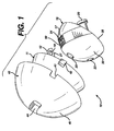
- Figure 1 illustrates an exploded perspective view of the trial of the present invention from an antero-medial view;
- Figure 2 illustrates a cross-section of the trial of Figure 1;
- Figure 3 illustrates an exploded perspective view from the anterior side of the trial of the present invention;
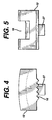
- Figure 4 illustrates a side view of pawl insert of the trial of Figure 1;
- Figure 5 illustrates a front view of the pawl insert of the trial of Figure 1;
- Figure 6 illustrates an exploded perspective view of the trial cup of Figure 1 with a reference pin inserting instrument; and
- Figure 7 illustrates a cross-section of the trial of Figure 1 with a femoral component.
-
- Referring now to Figures 1 through 6 there is illustrated a
acetabular trial system 10 of the present invention, comprising inner cup or bearing 15, an outer bearing ormiddle cup 11 and anouter augmentation shell 40. Theaugmentation shell 40 comprises an outerspherical surface 45 to interface with a patient's acetabulum, adistal opening 46 forming an innerspherical surface 47 for receiving theouter bearing 11 of thetrial 10, aslot 44 in top of theshell 40 for receiving a reference pin therethrough, andslots 41 for receivingtabs 42 on theouter bearing 11. - Preferably, a plurality of
augmentation shells 40 are used having multiple diameters, typically from about 40mm to about 70mm, to accommodate the various patient acetabula sizes. The inner diameter is uniform for each of the shells so that each closely fits with the outer diameter of theouter bearing 11, thus allowing use of the same outer andinner bearings inner bearings 15 have a variety of inner diameter sizes to accomodate a variety of head sizes, thereby permitting the surgeon flexibility in selecting a desireable head size for the femoral component of an implant. - The
augmentation shell 40 includes pins 22 extending in a superior-medial direction from theshell 40. The pins 22 are used to temporarily fix theshell 40 into the acetabulum of a patient at an abduction angle generally at about 40°. - The
outer bearing 11 comprises anopening 21 for receiving apin 20 for rotatably attaching an inner bearing 15 inside theouter bearing 11. Theouter bearing 11 further includes arecess 14 for receiving a spring-loadedpawl insert 12. - The
pawl insert 12 includesteeth 16 for engaging theserrations 17 on the outer surface of the inner bearing 15 and arecess 18 for receivingleaf spring 19 which biases thepawl 12 in a direction towards the inner bearing 15. - The
outer bearing 11 also includes aslot 35 in the top which serves as an aperture into which areference screw 36 may be inserted through thetrial 10 into the acetabulum bone. - The
inner bearing 15 comprises ahole 33 having an axis perpendicular the plane of therim 34 of the inner bearing. Thehole 33 of theinner bearing 15 is always contained within the extents of theslot 35 of theouter bearing 11 and theslot 44 of theshell 40 throughout the entire range of motion of the inner bearing with respect toouter bearing 11 andshell 40. - The inner bearing 15 comprises an opening 23 for receiving
pin 20. The opening 23 is aligned with the opening 21 of theouter bearing 11 whenpin 20 is inserted throughopenings pin 20 permits the inner bearing 15 to rotate about the axis 9 of thepin 20, with respect toouter bearing 11. Theinner bearing 15 further comprisesserrations 17 which are located on theouter surface 30 of the inner bearing at a 90° angle from theopening 23, i.e., the axis 9 of thepin 20. Agroove 24 is formed in theouter surface 30 of theinner bearing 15 through theserrations 17. Thegroove 24 extends 20° on each side of amiddle point 50 within thegroove 24. Themiddle point 50 is defined by the plane of symmetry of the device. Atab 27 located on thepawl 12 fits withingroove 24 and permits rotation of theinner bearing 15 aboutpin 20 for 20° on either side of themiddle point 50 of thegroove 24. Thespring 19 biases thepawl 12 in a direction towards theserrations 17 causing theteeth 16 of thepawl 12 to engage with theserrations 17. Theserrations 17 are spaced in preset angular increments preferably of about 2.5°. - In use, an
appropriate size shell 40 is selected and fitted into the acetabulum of a patient who is to receive an artificial hip implant including an acetabular cup. The pins 22 are used to temporarily fix theouter shell 40 to the acetabulum at a 40° abduction angle. - The
inner bearing 15 as assembled is inserted into theouter bearing 11 such that theopening 23 of theinner bearing 15 is aligned with theopening 21 of theouter bearing 11 and so that thetab 27 of thepawl 12 is located within thegroove 24 on the outer surface of theinner bearing 15. As assembled, thepin 20 is inserted throughopenings inner bearing 15 to theouter bearing 11. The horizontal axis of thepin 20 defines an axis of rotation of the anteversion angle. - The assembly of the outer and
inner bearing shell opening 46 forming the inner arcuate orspherical surface 47. Thetabs 42 of theouter bearing 11 fit intoslots 41 within theaugmentation shell 40, thus aligning and holding itself within theaugmentation shell 40. - Referring now to Figure 7 a
femoral component 51 is illustrated in use with theacetabular trial sytem 10. Thefemoral component 51 comprises ahead portion 52 comprising a convex spherical surface for articulating within the inner bearing orcup 15. Thehead portion 52 is coupled to aneck 53 which is then coupled to ashank portion 54 to be placed within a femoral cavity of a pateint's hip. The femoral component is most preferrably a femoral trial, although the actual femoral component implant may be used as the femoral component with theacetabular trial system 10. Theneck 53 is preferrably a separate piece to be assembled with thehead portion 52 andshank portion 54. Theshank portion 54 may be a broach used to remove bone material within the femoral cavity or may be a stem trial or the stem of femoral component implant. The trial or implant or trial may be for a cemented type implant or a press-fit type implant. - In use, the
femoral component 51 is placed in a prepared femoral cavity of a patient's hip and thehead 52 of thefemoral component 51 is inserted into theinner bearing 15 and the joint is reduced. Thefemoral component 51 may then be rotated to an extreme in all directions with respect to theacetabular trial 10 by rotating, extending, flexing, adducting and abducting the hip joint. In doing so the range of motion of the hip is imitated. - If the
neck 53 of thefemoral component 51 contacts theedge 28 of theinner bearing 15 at such points on theedge 28 that the contact force creates a torque which is substantially about the axis of thepin 20, then theinner bearing 15 will rotate. However, because of thepawl 12 contacting theserrations 17 of theinner bearing 15, some resistance will be felt by the surgeon and an auditory feedback will be caused by the movement of thepawl 12 over theserrations 17. This rotation is limited by thetab 27 of thepawl 12 hitting the end of thegroove middle point 50 of thegroove 24. Thus, after theinner bearing 15 is rotated, thepawl 12 will hold the inner bearing in place. - If the
trial 10 is removed, theinner bearing 15 will show the appropriate anteversion angle or position for setting the ultimate desired acetabular cup implant position. Indicatinglines 29 will show the appropriate anteversion angle at the point that such line abuts theedge 48 of therim 32 of theouter bearing 11. Also, once the anteversion angle is set using this technique, thereference screw 36 is inserted into the bone throughinner bearing hole 33, andslots outer bearing 11 andshell 40 respectively. Thereference screw 36 comprises ahexagonal socket head 37 andthreads 38. A screw insertion rod 39 (Figure 6) is used to insert the screw throughhole 33 andslots insertion rod 39 is then removed from thescrew 36 and thetrial 10 is removed from the acetabulum, leaving thescrew 36 in place as a reference for cup implant placement. - The acetabular cup implant is placed over the
head 37 of thereference screw 36. Thus, the acetabular cup implant is oriented and positioned just as thetrial 10 had been. In the case of a cemented implant, an addition trial having an apical central hole may be used to demarcate the desired position. The trial is inserted over the rod orpin 39 and the location of the trial is marked. The cemnted implant may then be inserted and aligned with the marks. This is necessary due to the fact that the cemented cup preferably should not have a central hole. - The desired angle may also be verified upon remaoval of the
trial 10 from the acetabulum with the indicatinglines 29 as described above. Finally, using theinsertion rod 39, thereference screw 36 is removed through the acetabular cup implant's apical hole, without disturbing the placement of the cup. - In an alternative embodiment,
bearings outer bearing 11 acts as the outer shell and is fixed into place in the acetabulum using pins in a similar manner as described above with respect to theshell 40. - Although the present invention is described with respect to a particular embodiment it will be apparent to those skilled in the art that various modifications may be made without departing from the scope of the invention. For example, the abduction angle may be set using the same device by placing the fixation pin in a position where it will allow the inner cup to rotate about the anterior-posterior axis. It may also be desirable to orient the hip about a different axis to optimize hip placement. In each of such circumstances, the two cup system and method as described and claimed herein may be used.
Claims (12)
- A acetabular trial system (10) for use in prosthetic hip implantation surgery, said system comprising:an outer shell (11; 40) for placement on an acetabulum of a patient;an inner cup (15) for placement within said outer shell along a longitudinal axis; anda fixation device (20; 11, 20) to rotatably fix said inner cup (15) within said outer shell (11; 40) to permit said inner cup (15) to rotate about a transverse axis (9).
- The system of claim 1 further comprising:a restriction device (12) engaging said inner cup with said outer shell to restrict the rotation of said inner cup about said axis.
- The trial system of claim 2 wherein said restriction device further comprises a spring-loaded ratchet (12) for incrementally permitting rotation of said inner cup about said axis.
- The trial system of claim 1, 2 or 3 further comprising an anteversion angle indicator (29) located on said inner cup.
- The trial system of claim 1 comprising a plurality of said inner cups (15) having a plurality of inner cup diameters; wherein one of said inner cups having a preferred diameter may be selected from said plurality of inner cups for a hip trial reduction.
- The trial system of claim 1 further comprising:a middle cup (11) positionable within said outer shell (40) between said outer shell and said inner cup, said middle cup having an outer diameter;wherein said outer shell has an inner diameter, said outer diameter of said middle cup fitting within said inner diameter of said outer shell; andwherein said fixation device (20) rotatably couples said inner cup with said middle cup to permit said inner cup to rotate with respect to said middle cup.
- The trial system of claim 6 further comprising:a plurality of said outer shells (40) having a plurality of outer diameter sizes, wherein said inner diameter of each of said outer shell is uniform in size with respect to the inner diameter of each of the other of said plurality of outer shells.
- The trial system of claim 6 further comprising a reference pin (36) wherein said outer shell, middle cup and inner cup each comprise an opening (33, 35, 44) for receiving said pin; wherein each said opening is aligned with the other said openings so that said pin may be passed therethrough and into bone of an acetabulum in which said outer shell is placed.
- The trial system of claim 8 wherein said inner cup is orientable about a transverse axis defining a range of anteversion angles; and
wherein said openings in said middle cup and outer shell permit movement of said pin in said openings of said middle cup and said outer shell throughout said range of angles. - The trial system of claim 6 comprising a plurality of said inner cups (15) having a plurality of inner cup diameters; wherein one of said inner cups having a preferred diameter may be selected from said plurality of inner cups for a hip trial reduction.
- The trial system of claim 1 further comprising a reference pin (36);
wherein said outer shell and inner cup each comprise an opening (33, 35; 33, 44) for receiving said pin wherein each said opening is aligned with the other of said openings so that said pin may be passed therethrough and into the bone of an acetabulum into which said outer shell is inserted. - The trial system of claim 1 further comprising a reference pin (36);wherein said outer shell and inner cup each comprise an opening (33, 35; 33, 44) for receiving said pin wherein each said opening is aligned with the other of said openings so that said pin may be passed therethrough and into the bone of an acetabulum into which said outer shell is inserted;wherein said inner cup is rotatable about a selected axis defining a range of cup placement angles with respect to said axis; andwherein said openings align throughout said range so that said reference pin may be inserted through said openings throughout said range.
Applications Claiming Priority (2)
| Application Number | Priority Date | Filing Date | Title |
|---|---|---|---|
| US649150 | 1996-05-17 | ||
| US08/649,150 US5879401A (en) | 1996-05-17 | 1996-05-17 | Acetabular trial |
Publications (3)
| Publication Number | Publication Date |
|---|---|
| EP0807426A2 EP0807426A2 (en) | 1997-11-19 |
| EP0807426A3 EP0807426A3 (en) | 1998-11-18 |
| EP0807426B1 true EP0807426B1 (en) | 2003-10-01 |
Family
ID=24603671
Family Applications (1)
| Application Number | Title | Priority Date | Filing Date |
|---|---|---|---|
| EP97303331A Expired - Lifetime EP0807426B1 (en) | 1996-05-17 | 1997-05-16 | Acetabular trial |
Country Status (3)
| Country | Link |
|---|---|
| US (1) | US5879401A (en) |
| EP (1) | EP0807426B1 (en) |
| DE (1) | DE69725209T2 (en) |
Cited By (17)
| Publication number | Priority date | Publication date | Assignee | Title |
|---|---|---|---|---|
| US7678150B2 (en) | 2004-06-15 | 2010-03-16 | Tornier Sas | Total shoulder prosthesis of an inverted type |
| US7887544B2 (en) | 2003-03-10 | 2011-02-15 | Tornier Sas | Ancillary tool for positioning a glenoid implant |
| US8021432B2 (en) | 2005-12-05 | 2011-09-20 | Biomet Manufacturing Corp. | Apparatus for use of porous implants |
| US8066778B2 (en) | 2005-04-21 | 2011-11-29 | Biomet Manufacturing Corp. | Porous metal cup with cobalt bearing surface |
| US8080063B2 (en) | 2006-04-13 | 2011-12-20 | Tornier Sas | Glenoid component with an anatomically optimized keel |
| US8123814B2 (en) | 2001-02-23 | 2012-02-28 | Biomet Manufacturing Corp. | Method and appartus for acetabular reconstruction |
| US8197550B2 (en) | 2005-04-21 | 2012-06-12 | Biomet Manufacturing Corp. | Method and apparatus for use of porous implants |
| US8266780B2 (en) | 2005-04-21 | 2012-09-18 | Biomet Manufacturing Corp. | Method and apparatus for use of porous implants |
| US8277511B2 (en) | 2006-04-21 | 2012-10-02 | Tornier Sas | Shoulder or hip prosthesis and method for setting same |
| US8292967B2 (en) | 2005-04-21 | 2012-10-23 | Biomet Manufacturing Corp. | Method and apparatus for use of porous implants |
| US8303665B2 (en) | 2004-06-15 | 2012-11-06 | Tornier Sas | Glenoidal component, set of such components and shoulder prosthesis incorporating such a glenoidal component |
| US8864834B2 (en) | 2007-01-30 | 2014-10-21 | Tornier Sas | Method and apparatus for fitting a shoulder prosthesis |
| US8974536B2 (en) | 2007-01-30 | 2015-03-10 | Tornier Sas | Intra-articular joint replacement |
| US9408652B2 (en) | 2010-04-27 | 2016-08-09 | Tornier Sas | Intra-articular joint replacement and method |
| US9433507B2 (en) | 2006-03-21 | 2016-09-06 | Tornier, Inc. | Non-spherical articulating surfaces in shoulder and hip replacement |
| US9474619B2 (en) | 2006-03-21 | 2016-10-25 | Tornier, Inc. | Glenoid component with improved fixation stability |
| US10631993B2 (en) | 2010-10-22 | 2020-04-28 | Tornier, Inc. | Set of glenoid components for a shoulder prosthesis |
Families Citing this family (73)
| Publication number | Priority date | Publication date | Assignee | Title |
|---|---|---|---|---|
| US7255712B1 (en) * | 1997-04-15 | 2007-08-14 | Active Implants Corporation | Bone growth promoting implant |
| FR2781362B1 (en) * | 1998-07-24 | 2000-11-24 | Michel Henry Fessy | COTYL CUP FOR HIP PROSTHESIS |
| FR2782262B1 (en) * | 1998-08-17 | 2001-02-09 | Michel Porte | TEST OR IMPLANTABLE COTYLE WITH ADJUSTABLE ORIENTATION |
| FR2790662B1 (en) * | 1999-03-11 | 2001-06-08 | Michel Porte | PROTHETIC COTYLE WITH ANCHORING PIONS |
| IT1311547B1 (en) * | 1999-09-09 | 2002-03-13 | Lima Lto Spa | ACETABULAR HIP PROSTHESIS. |
| FR2801193B1 (en) * | 1999-11-19 | 2002-02-15 | Proconcept | DOUBLE MOBILITY EXPANDABLE COTYLOIDAL PROSTHESIS |
| FR2809305B1 (en) * | 2000-05-26 | 2003-04-04 | Amplitude | ANCILLARY INSTRUMENT FOR LAYING A COTYLOIDIAN CUP FOR A HIP JOINT PROSTHESIS |
| US7291177B2 (en) * | 2001-02-23 | 2007-11-06 | Biomet Manufacturing Corp. | Method and apparatus for acetabular reconstruction |
| US7713306B2 (en) * | 2001-02-23 | 2010-05-11 | Biomet Manufacturing Corp. | Method and apparatus for acetabular reconstruction |
| FR2827154B1 (en) * | 2001-07-16 | 2004-04-30 | Jean Yves Lazennec | COTYLOID IMPLANT FOR HIP PROSTHESIS |
| CN1596091A (en) | 2001-12-04 | 2005-03-16 | 迪斯酋有限公司 | Implants for load bearing applications |
| ES2323775T3 (en) * | 2002-05-23 | 2009-07-24 | Active Implants Corporation | DENTAL AND ARTICULATION IMPLANTS. |
| US7179297B2 (en) | 2002-09-17 | 2007-02-20 | Smith & Nephew, Inc. | Combined bipolar and unipolar trials |
| US6926740B2 (en) | 2002-12-13 | 2005-08-09 | Depuy Products, Inc. | Modular orthopaedic implant apparatus and method |
| CA2439850A1 (en) | 2003-09-04 | 2005-03-04 | Orthosoft Inc. | Universal method for determining acetabular and femoral implant positions during navigation |
| AU2003266405A1 (en) * | 2003-09-27 | 2005-05-11 | Aesculap Ag And Co. Kg | Method and device for determination of the mobility of a hip joint prosthesis |
| FR2872025B1 (en) * | 2004-06-28 | 2006-08-25 | Tornier Sas | PROSTHESIS OF SHOULDER OR HIP |
| US20050288793A1 (en) * | 2004-06-28 | 2005-12-29 | Howmedica Osteonics Corp. | Internal fixation element for hip acetabular shell |
| GB0420346D0 (en) | 2004-09-13 | 2004-10-13 | Finsbury Dev Ltd | Tool |
| US7892287B2 (en) * | 2004-09-27 | 2011-02-22 | Depuy Products, Inc. | Glenoid augment and associated method |
| US7922769B2 (en) * | 2004-09-27 | 2011-04-12 | Depuy Products, Inc. | Modular glenoid prosthesis and associated method |
| US20060074353A1 (en) * | 2004-09-27 | 2006-04-06 | Deffenbaugh Daren L | Glenoid instrumentation and associated method |
| US7927335B2 (en) | 2004-09-27 | 2011-04-19 | Depuy Products, Inc. | Instrument for preparing an implant support surface and associated method |
| GB2420715B (en) * | 2004-12-06 | 2009-01-28 | Univ Hospital Birmingham Nhs F | Improvements in and relating to arthroplastic surgical apparatus |
| US20060190089A1 (en) * | 2005-02-18 | 2006-08-24 | Howmedica Osteonics Corp. | Internal adaptor for hip acetabular cage |
| US20070106392A1 (en) * | 2005-11-08 | 2007-05-10 | Howmedica Osteonics Corp. | Acetabular cup locking mechanism |
| US7635447B2 (en) * | 2006-02-17 | 2009-12-22 | Biomet Manufacturing Corp. | Method and apparatus for forming porous metal implants |
| CN103202736B (en) | 2006-03-20 | 2016-06-15 | 史密夫和内修有限公司 | Acetabular cup for multiple supporting material |
| US20070225821A1 (en) | 2006-03-21 | 2007-09-27 | Axiom Orthopaedics, Inc. | Femoral and humeral stem geometry and implantation method for orthopedic joint reconstruction |
| US20080053169A1 (en) * | 2006-08-30 | 2008-03-06 | Victoria Marie Ricker | Theft deterrent device for bags |
| US8328873B2 (en) | 2007-01-10 | 2012-12-11 | Biomet Manufacturing Corp. | Knee joint prosthesis system and method for implantation |
| US8163028B2 (en) | 2007-01-10 | 2012-04-24 | Biomet Manufacturing Corp. | Knee joint prosthesis system and method for implantation |
| US8562616B2 (en) | 2007-10-10 | 2013-10-22 | Biomet Manufacturing, Llc | Knee joint prosthesis system and method for implantation |
| US8187280B2 (en) | 2007-10-10 | 2012-05-29 | Biomet Manufacturing Corp. | Knee joint prosthesis system and method for implantation |
| JP5448842B2 (en) | 2007-01-10 | 2014-03-19 | バイオメト マニファクチャリング コーポレイション | Knee joint prosthesis system and implantation method |
| CN101842062B (en) * | 2007-09-25 | 2013-04-03 | 拜欧米特制造公司 | Cementless tibial tray |
| US8808390B2 (en) * | 2007-09-27 | 2014-08-19 | DePuy Synthes Products, LLC | Acetabular prosthesis having an orientable face |
| GB0803723D0 (en) | 2008-02-29 | 2008-04-09 | Depuy Int Ltd | An instrument for use in a joint replacement procedure |
| DE102008047627A1 (en) * | 2008-08-01 | 2010-02-04 | Smith & Nephew Orthopaedics Ag | Positioning aid in the form of a self-fixing trial acetabulum |
| US8123815B2 (en) | 2008-11-24 | 2012-02-28 | Biomet Manufacturing Corp. | Multiple bearing acetabular prosthesis |
| US8403995B2 (en) | 2008-12-18 | 2013-03-26 | Depuy Products, Inc. | Device and method for determining proper seating of an orthopaedic prosthesis |
| US8075629B2 (en) | 2008-12-18 | 2011-12-13 | Depuy Products, Inc. | Orthopaedic prosthesis having a seating indicator |
| US8241365B2 (en) * | 2008-12-23 | 2012-08-14 | Depuy Products, Inc. | Shoulder prosthesis with vault-filling structure having bone-sparing configuration |
| JP2012525942A (en) * | 2009-05-07 | 2012-10-25 | スミス アンド ネフュー インコーポレーテッド | Modular trial prosthesis head |
| US8308810B2 (en) | 2009-07-14 | 2012-11-13 | Biomet Manufacturing Corp. | Multiple bearing acetabular prosthesis |
| US8231683B2 (en) * | 2009-12-08 | 2012-07-31 | Depuy Products, Inc. | Shoulder prosthesis assembly having glenoid rim replacement structure |
| FR2958533B1 (en) * | 2010-04-08 | 2012-03-23 | Jean Claude Cartillier | RANGE OF COTYLOID IMPLANTS OF DIFFERENT SIZES |
| EP2598084B1 (en) | 2010-07-29 | 2016-08-31 | Mayo Foundation For Medical Education And Research | Acetabular cup prosthesis |
| US8465548B2 (en) | 2010-11-24 | 2013-06-18 | DePuy Synthes Products, LLC | Modular glenoid prosthesis |
| US8480750B2 (en) | 2010-11-24 | 2013-07-09 | DePuy Synthes Products, LLC | Modular glenoid prosthesis |
| US9023112B2 (en) * | 2011-02-24 | 2015-05-05 | Depuy (Ireland) | Maintaining proper mechanics THA |
| US20120219790A1 (en) * | 2011-02-25 | 2012-08-30 | Frito-Lay North America, Inc. | Compostable film with paper-like, writable surface |
| US9421106B2 (en) | 2011-12-07 | 2016-08-23 | Howmedica Osteonics Corp. | Reverse shoulder baseplate with alignment guide for glenosphere |
| CN102688097B (en) * | 2012-05-14 | 2014-11-26 | 清华大学 | Attitude acquisition method and system for acetabulum and femoral head in artificial hip joint replacement |
| US8663334B2 (en) | 2012-05-31 | 2014-03-04 | Howmedica Osteonics Corp. | Lateral entry insert for cup trial |
| US8906102B2 (en) | 2012-05-31 | 2014-12-09 | Howmedica Osteonics Corp. | Lateral entry insert for cup trial |
| US9308102B2 (en) | 2013-03-04 | 2016-04-12 | Howmedica Osteonics Corp. | Acetabular cup positioning device |
| JP6772060B2 (en) * | 2013-04-26 | 2020-10-21 | スミス アンド ネフュー インコーポレイテッド | Acetabular implant alignment device and method |
| ITUD20130074A1 (en) * | 2013-05-24 | 2014-11-25 | Limacorporate Spa | ACETABULAR PROSTHESIS |
| ITVR20130271A1 (en) * | 2013-12-05 | 2015-06-06 | Quantum Technology S R L | DEVICE FOR ASSESSING CHARACTERISTICS OF A PATIENT AT THE END OF THE CORRECT APPLICATION TO ITS PROSTHESIS. |
| US9724201B2 (en) | 2015-06-30 | 2017-08-08 | Depuy Ireland Unlimited Company | Modular taper seal for orthopaedic prosthetic hip assembly |
| NZ739167A (en) | 2015-07-27 | 2023-11-24 | Hip Innovation Technology Llc | Tool and method for separating a femoral cup from an acetabular ball in an implanted hip prosthesis |
| KR20180061145A (en) * | 2015-08-21 | 2018-06-07 | 힙 이노베이션 테크놀러지 엘엘씨 | Surgical trays, tools and methods for implanting hip replacement prostheses |
| ITUB20153403A1 (en) * | 2015-09-03 | 2017-03-03 | Aeron Srl | DEVICE FOR ASSESSING CHARACTERISTICS OF A PATIENT AT THE END OF THE CORRECT APPLICATION TO ITS PROSTHESIS. |
| US10390972B2 (en) | 2016-01-15 | 2019-08-27 | Howmedica Osteonics Corp. | Humeral trial adaptor |
| US10111754B2 (en) | 2016-09-30 | 2018-10-30 | Depuy Ireland Unlimited Company | Acetabular shell and liner system |
| GB201705920D0 (en) | 2017-04-12 | 2017-05-24 | Depuy Ireland Ultd Co | Apparatus and method for hip surgery |
| US11376128B2 (en) | 2018-12-31 | 2022-07-05 | Depuy Ireland Unlimited Company | Acetabular orthopaedic prosthesis and method |
| US11413152B2 (en) * | 2019-11-26 | 2022-08-16 | Depuy Ireland Unlimited Company | Modular acetabular trial liner system |
| US11291549B2 (en) | 2019-12-11 | 2022-04-05 | Depuy Ireland Unlimited Company | Ceramic acetabular shell liners with augments |
| US11628066B2 (en) | 2019-12-11 | 2023-04-18 | Depuy Ireland Unlimited Company | Ceramic acetabular shell liner with a metal ring having a lead-in surface |
| USD952848S1 (en) * | 2020-11-05 | 2022-05-24 | Shukla Medical | Measurement guide for an acetabular cup extractor |
| EP4230048A1 (en) | 2022-02-18 | 2023-08-23 | Antje Albeck | Method and device for implementing a maturation process of sausage goods |
Family Cites Families (10)
| Publication number | Priority date | Publication date | Assignee | Title |
|---|---|---|---|---|
| FR2148322B1 (en) * | 1971-07-22 | 1975-02-07 | Proteor Sa | |
| US4135517A (en) * | 1977-07-21 | 1979-01-23 | Minnesota Mining And Manufacturing Company | Femoral prosthesis trial fitting device |
| DE3205526A1 (en) * | 1982-02-12 | 1983-09-01 | Mecron Medizinische Produkte Gmbh, 1000 Berlin | Stencil for the application of reception holes in the hip region, and a basket therefor |
| US4642123A (en) * | 1983-03-08 | 1987-02-10 | Joint Medical Products Corporation | Ball and socket bearing for artificial joint |
| CH673766A5 (en) * | 1988-03-01 | 1990-04-12 | Sulzer Ag | |
| US5176711A (en) * | 1991-03-06 | 1993-01-05 | Grimes James B | Acetabular revision system |
| US5320625A (en) * | 1993-01-21 | 1994-06-14 | Bertin Kim C | Apparatus and method for implanting a prosthetic acetabular cup and then testing the stability of the implant |
| US5507824A (en) * | 1993-02-23 | 1996-04-16 | Lennox; Dennis W. | Adjustable prosthetic socket component, for articulating anatomical joints |
| US5431657A (en) * | 1994-05-23 | 1995-07-11 | Zimmer, Inc. | Instrument for installing an acetabular cup assembly |
| US5571111A (en) * | 1995-05-01 | 1996-11-05 | Aboczky; Robert I. | Instrument for orienting, inserting and impacting an acetabular cup prosthesis including prosthesis retaining head arrangement |
-
1996
- 1996-05-17 US US08/649,150 patent/US5879401A/en not_active Expired - Lifetime
-
1997
- 1997-05-16 DE DE69725209T patent/DE69725209T2/en not_active Expired - Lifetime
- 1997-05-16 EP EP97303331A patent/EP0807426B1/en not_active Expired - Lifetime
Cited By (25)
| Publication number | Priority date | Publication date | Assignee | Title |
|---|---|---|---|---|
| US8123814B2 (en) | 2001-02-23 | 2012-02-28 | Biomet Manufacturing Corp. | Method and appartus for acetabular reconstruction |
| US9375316B2 (en) | 2001-02-23 | 2016-06-28 | Biomet Manufacturing, Llc. | Method and apparatus for acetabular reconstruction |
| US8551181B2 (en) | 2001-02-23 | 2013-10-08 | Biomet Manufacturing, Llc | Method and apparatus for acetabular reconstruction |
| US8187282B2 (en) | 2003-03-10 | 2012-05-29 | Tornier Sas | Ancillary tool for positioning a glenoid implant |
| US7887544B2 (en) | 2003-03-10 | 2011-02-15 | Tornier Sas | Ancillary tool for positioning a glenoid implant |
| US8303665B2 (en) | 2004-06-15 | 2012-11-06 | Tornier Sas | Glenoidal component, set of such components and shoulder prosthesis incorporating such a glenoidal component |
| US7678150B2 (en) | 2004-06-15 | 2010-03-16 | Tornier Sas | Total shoulder prosthesis of an inverted type |
| US9545312B2 (en) | 2004-06-15 | 2017-01-17 | Tornier Sas | Glenoidal component, set of such components and shoulder prosthesis incorporating such a glenoidal component |
| US10610363B2 (en) | 2004-06-15 | 2020-04-07 | Tornier Sas | Glenoidal component, set of such components and shoulder prosthesis incorporating such a glenoidal component |
| US11523907B2 (en) | 2004-06-15 | 2022-12-13 | Tornier Sas | Glenoidal component, set of such components and shoulder prosthesis incorporating such a glenoidal component |
| US8197550B2 (en) | 2005-04-21 | 2012-06-12 | Biomet Manufacturing Corp. | Method and apparatus for use of porous implants |
| US8292967B2 (en) | 2005-04-21 | 2012-10-23 | Biomet Manufacturing Corp. | Method and apparatus for use of porous implants |
| US8266780B2 (en) | 2005-04-21 | 2012-09-18 | Biomet Manufacturing Corp. | Method and apparatus for use of porous implants |
| US8066778B2 (en) | 2005-04-21 | 2011-11-29 | Biomet Manufacturing Corp. | Porous metal cup with cobalt bearing surface |
| US8021432B2 (en) | 2005-12-05 | 2011-09-20 | Biomet Manufacturing Corp. | Apparatus for use of porous implants |
| US9433507B2 (en) | 2006-03-21 | 2016-09-06 | Tornier, Inc. | Non-spherical articulating surfaces in shoulder and hip replacement |
| US9474619B2 (en) | 2006-03-21 | 2016-10-25 | Tornier, Inc. | Glenoid component with improved fixation stability |
| US8080063B2 (en) | 2006-04-13 | 2011-12-20 | Tornier Sas | Glenoid component with an anatomically optimized keel |
| US8277511B2 (en) | 2006-04-21 | 2012-10-02 | Tornier Sas | Shoulder or hip prosthesis and method for setting same |
| US9089435B2 (en) | 2007-01-30 | 2015-07-28 | Tornier Sas | Intra-articular joint replacement |
| US8974536B2 (en) | 2007-01-30 | 2015-03-10 | Tornier Sas | Intra-articular joint replacement |
| US8864834B2 (en) | 2007-01-30 | 2014-10-21 | Tornier Sas | Method and apparatus for fitting a shoulder prosthesis |
| US9408652B2 (en) | 2010-04-27 | 2016-08-09 | Tornier Sas | Intra-articular joint replacement and method |
| US10631993B2 (en) | 2010-10-22 | 2020-04-28 | Tornier, Inc. | Set of glenoid components for a shoulder prosthesis |
| US11304815B2 (en) | 2010-10-22 | 2022-04-19 | Howmedica Osteonics Corp. | Set of glenoid components for a shoulder prosthesis |
Also Published As
| Publication number | Publication date |
|---|---|
| US5879401A (en) | 1999-03-09 |
| DE69725209D1 (en) | 2003-11-06 |
| DE69725209T2 (en) | 2004-08-05 |
| EP0807426A3 (en) | 1998-11-18 |
| EP0807426A2 (en) | 1997-11-19 |
Similar Documents
| Publication | Publication Date | Title |
|---|---|---|
| EP0807426B1 (en) | Acetabular trial | |
| US11298233B2 (en) | Method of implanting joint prosthesis with infinitely positionable head | |
| US6702824B2 (en) | Prosthesis positioning apparatus | |
| US7794503B2 (en) | Trialing system and method for modular hip joint replacement system | |
| EP1435223B1 (en) | Instrument for trialing for modular hip stems | |
| EP1482878B1 (en) | Intramedullary trial fixation device | |
| US7828806B2 (en) | Accessory for implanting a hip endoprosthesis, and method for manipulating the same | |
| EP1437107B1 (en) | Alignment device for modular implants | |
| US5860969A (en) | Version adjustment instrument for modular femoral components and method of using same | |
| US8070822B1 (en) | Tool for controlling the mutual angle between the parts of an artificial hip joint | |
| WO2014108540A1 (en) | Cap for use with acetabular cup |
Legal Events
| Date | Code | Title | Description |
|---|---|---|---|
| PUAI | Public reference made under article 153(3) epc to a published international application that has entered the european phase |
Free format text: ORIGINAL CODE: 0009012 |
|
| AK | Designated contracting states |
Kind code of ref document: A2 Designated state(s): DE GB IE |
|
| PUAL | Search report despatched |
Free format text: ORIGINAL CODE: 0009013 |
|
| AK | Designated contracting states |
Kind code of ref document: A3 Designated state(s): DE GB IE |
|
| 17P | Request for examination filed |
Effective date: 19990430 |
|
| 17Q | First examination report despatched |
Effective date: 20010618 |
|
| RAP1 | Party data changed (applicant data changed or rights of an application transferred) |
Owner name: DEPUY PRODUCTS, INC. |
|
| GRAH | Despatch of communication of intention to grant a patent |
Free format text: ORIGINAL CODE: EPIDOS IGRA |
|
| RAP1 | Party data changed (applicant data changed or rights of an application transferred) |
Owner name: DEPUY PRODUCTS, INC. |
|
| GRAH | Despatch of communication of intention to grant a patent |
Free format text: ORIGINAL CODE: EPIDOS IGRA |
|
| GRAA | (expected) grant |
Free format text: ORIGINAL CODE: 0009210 |
|
| AK | Designated contracting states |
Kind code of ref document: B1 Designated state(s): DE GB IE |
|
| REG | Reference to a national code |
Ref country code: GB Ref legal event code: FG4D |
|
| REG | Reference to a national code |
Ref country code: IE Ref legal event code: FG4D |
|
| REF | Corresponds to: |
Ref document number: 69725209 Country of ref document: DE Date of ref document: 20031106 Kind code of ref document: P |
|
| PLBE | No opposition filed within time limit |
Free format text: ORIGINAL CODE: 0009261 |
|
| STAA | Information on the status of an ep patent application or granted ep patent |
Free format text: STATUS: NO OPPOSITION FILED WITHIN TIME LIMIT |
|
| 26N | No opposition filed |
Effective date: 20040702 |
|
| PGFP | Annual fee paid to national office [announced via postgrant information from national office to epo] |
Ref country code: IE Payment date: 20130510 Year of fee payment: 17 Ref country code: DE Payment date: 20130515 Year of fee payment: 17 Ref country code: GB Payment date: 20130515 Year of fee payment: 17 |
|
| REG | Reference to a national code |
Ref country code: DE Ref legal event code: R119 Ref document number: 69725209 Country of ref document: DE |
|
| GBPC | Gb: european patent ceased through non-payment of renewal fee |
Effective date: 20140516 |
|
| REG | Reference to a national code |
Ref country code: IE Ref legal event code: MM4A |
|
| REG | Reference to a national code |
Ref country code: DE Ref legal event code: R119 Ref document number: 69725209 Country of ref document: DE Effective date: 20141202 |
|
| PG25 | Lapsed in a contracting state [announced via postgrant information from national office to epo] |
Ref country code: IE Free format text: LAPSE BECAUSE OF NON-PAYMENT OF DUE FEES Effective date: 20140516 Ref country code: DE Free format text: LAPSE BECAUSE OF NON-PAYMENT OF DUE FEES Effective date: 20141202 |
|
| PG25 | Lapsed in a contracting state [announced via postgrant information from national office to epo] |
Ref country code: GB Free format text: LAPSE BECAUSE OF NON-PAYMENT OF DUE FEES Effective date: 20140516 |