EP0807810A1 - Vial autosampler - Google Patents
Vial autosampler Download PDFInfo
- Publication number
- EP0807810A1 EP0807810A1 EP97302641A EP97302641A EP0807810A1 EP 0807810 A1 EP0807810 A1 EP 0807810A1 EP 97302641 A EP97302641 A EP 97302641A EP 97302641 A EP97302641 A EP 97302641A EP 0807810 A1 EP0807810 A1 EP 0807810A1
- Authority
- EP
- European Patent Office
- Prior art keywords
- container
- seating
- station
- vial
- aperture
- Prior art date
- Legal status (The legal status is an assumption and is not a legal conclusion. Google has not performed a legal analysis and makes no representation as to the accuracy of the status listed.)
- Granted
Links
- 239000000463 material Substances 0.000 claims abstract description 33
- 238000002798 spectrophotometry method Methods 0.000 claims abstract description 22
- 238000005259 measurement Methods 0.000 claims description 32
- 238000004458 analytical method Methods 0.000 claims description 27
- 230000005670 electromagnetic radiation Effects 0.000 claims description 6
- 230000000717 retained effect Effects 0.000 claims description 6
- 238000006073 displacement reaction Methods 0.000 claims description 5
- 230000000694 effects Effects 0.000 claims description 5
- 230000000295 complement effect Effects 0.000 claims description 2
- 239000000523 sample Substances 0.000 description 25
- 239000000843 powder Substances 0.000 description 8
- 230000002093 peripheral effect Effects 0.000 description 4
- 230000002411 adverse Effects 0.000 description 3
- 239000000126 substance Substances 0.000 description 3
- 238000012986 modification Methods 0.000 description 2
- 230000004048 modification Effects 0.000 description 2
- 230000003287 optical effect Effects 0.000 description 2
- 239000010453 quartz Substances 0.000 description 2
- VYPSYNLAJGMNEJ-UHFFFAOYSA-N silicon dioxide Inorganic materials O=[Si]=O VYPSYNLAJGMNEJ-UHFFFAOYSA-N 0.000 description 2
- 229920000995 Spectralon Polymers 0.000 description 1
- 239000002783 friction material Substances 0.000 description 1
- 239000011521 glass Substances 0.000 description 1
- 230000005484 gravity Effects 0.000 description 1
- 239000007788 liquid Substances 0.000 description 1
- 239000002184 metal Substances 0.000 description 1
- 238000011017 operating method Methods 0.000 description 1
- -1 polytetrafluoroethylene Polymers 0.000 description 1
- 229920001343 polytetrafluoroethylene Polymers 0.000 description 1
- 239000004810 polytetrafluoroethylene Substances 0.000 description 1
- 238000004451 qualitative analysis Methods 0.000 description 1
- 239000012926 reference standard material Substances 0.000 description 1
- 238000006748 scratching Methods 0.000 description 1
- 230000002393 scratching effect Effects 0.000 description 1
- 230000001360 synchronised effect Effects 0.000 description 1
Images

Classifications
-
- G—PHYSICS
- G01—MEASURING; TESTING
- G01N—INVESTIGATING OR ANALYSING MATERIALS BY DETERMINING THEIR CHEMICAL OR PHYSICAL PROPERTIES
- G01N21/00—Investigating or analysing materials by the use of optical means, i.e. using sub-millimetre waves, infrared, visible or ultraviolet light
- G01N21/17—Systems in which incident light is modified in accordance with the properties of the material investigated
- G01N21/25—Colour; Spectral properties, i.e. comparison of effect of material on the light at two or more different wavelengths or wavelength bands
- G01N21/251—Colorimeters; Construction thereof
- G01N21/253—Colorimeters; Construction thereof for batch operation, i.e. multisample apparatus
-
- G—PHYSICS
- G01—MEASURING; TESTING
- G01N—INVESTIGATING OR ANALYSING MATERIALS BY DETERMINING THEIR CHEMICAL OR PHYSICAL PROPERTIES
- G01N21/00—Investigating or analysing materials by the use of optical means, i.e. using sub-millimetre waves, infrared, visible or ultraviolet light
- G01N21/17—Systems in which incident light is modified in accordance with the properties of the material investigated
- G01N21/25—Colour; Spectral properties, i.e. comparison of effect of material on the light at two or more different wavelengths or wavelength bands
- G01N21/31—Investigating relative effect of material at wavelengths characteristic of specific elements or molecules, e.g. atomic absorption spectrometry
- G01N21/35—Investigating relative effect of material at wavelengths characteristic of specific elements or molecules, e.g. atomic absorption spectrometry using infrared light
- G01N21/359—Investigating relative effect of material at wavelengths characteristic of specific elements or molecules, e.g. atomic absorption spectrometry using infrared light using near infrared light
-
- G—PHYSICS
- G01—MEASURING; TESTING
- G01N—INVESTIGATING OR ANALYSING MATERIALS BY DETERMINING THEIR CHEMICAL OR PHYSICAL PROPERTIES
- G01N35/00—Automatic analysis not limited to methods or materials provided for in any single one of groups G01N1/00 - G01N33/00; Handling materials therefor
- G01N35/02—Automatic analysis not limited to methods or materials provided for in any single one of groups G01N1/00 - G01N33/00; Handling materials therefor using a plurality of sample containers moved by a conveyor system past one or more treatment or analysis stations
- G01N35/025—Automatic analysis not limited to methods or materials provided for in any single one of groups G01N1/00 - G01N33/00; Handling materials therefor using a plurality of sample containers moved by a conveyor system past one or more treatment or analysis stations having a carousel or turntable for reaction cells or cuvettes
Definitions
- Spectrophotometers are well known to provide quantitive and qualitative analysis of substances and materials and are used extensively within the chemical, petro-chemical, food, agriculture and pharmaceutical industries.
- Typical infrared reflectance spectrophotometers are sold under the Trade Marks "COMPSCAN” by the Gardner Neotec Division of Pacific Scientific and "MODEL 6500” by NIR Systems Inc.
- spectrophotometers comprise a cell or container within which a sample of the material for analysis is retained; a source providing a beam of electromagnetic radiation (usually near infrared as previously mentioned) which is applied to the material in the cell, and sensors or detectors which are responsive to reflections from the material in the cell and provide an output from which the analysis is effected.
- the spectrophotometer is coupled to a computer by which the application of the beam to the material is controlled and which provides a required analysis of the output from the sensors or detectors.
- spectrophotometers present the light beam on to the sample material for analysis by way of a sheet material window (typically a sheet of optical quartz) which is translucent to the beam and light reflected (in the case of reflectance spectrophotometers) from the sample is redirected through the window to the sensors or detectors (signals from which provide an output for the analysis measurements).
- a sheet material window typically a sheet of optical quartz
- the window is disposed between the aforementioned apertured plate and the source of the near infrared light.
- the apparatus of the present invention is also provided in combination with an array of containers or cells within which samples of the material for analysis are accommodated (such samples may be of the same or different material).
- the container is preferably located at the seating of the station for the sample material to overlie the above mentioned aperture in the plate and to extend beyond the whole periphery of that aperture.
- the apertured plate can consequently serve to prevent the light beam which is directed through its aperture from being applied directly to peripheral parts of the container (which could otherwise develop spurious light reflections and adversely affect the accuracy of the spectrophotometric readings).
- the container will have a substantially flat wall part which fully overlies the aperture and extends beyond the whole periphery of that aperture and through which wall part the light beam is directed to the sample material which extends over the wall part.
- the aforementioned wall part of the container is conveniently arranged to abut the apertured plate to overlie the aperture therein.
- the apertured plate conveniently serves to protect the window from being damaged by the container (for example by preventing the successive containers in the array from scratching the surface of the window).
- the previously mentioned seating for a container when located at the station will usually be sized and profiled to accommodate a predetermined size and shape of container preferably to locate and retain that container in a predetermined position over the aperture of the aforementioned apertured plate.
- a preferred form of container is a conventional vial as typically used for housing pharmaceutical samples and having a substantially circular flat base and a substantially cylindrical side wall extending concentrically from the base; usually the light beam and, in the case of reflectance spectrophotometry, reflected light will be directed to and from the sample material in the vial through the flat base.
- a vial from the array of such containers will be located in a seating or otherwise at the station to ensure that its base fully overlies the aperture of the plate whilst the whole periphery of the base (comprising its junction with the cylindrical side wall) is located wholly outside the periphery of the aperture so that the light beam is applied to illuminate the sample material in the vial through the vial base at a position other than through the vial base at its junction with the side wall.
- the aperture in the plate can consequently serve to define or isolate for the light beam a predetermined target area on the base of the vial remote from the peripheral junction of the base with the vial side wall and over which target area the sample material is dispersed to be subjected to the light beam.
- the light beam is directed substantially vertically.
- the sample material for analysis is a powder
- the present invention may be applied to spectrophotometers in which the light beam is directed other than vertically.
- the apparatus of the present invention may be utilised for analysis of sample material in a form other than powder.
- the apparatus includes a spectrophotometer unit 1 for analysis of a sample material by reflectance measurements from a beam of near infrared light that is applied to the sample.
- the unit 1 is, conveniently, predominantly comprised of a generally known spectrophotometer unit, for example that as sold under the Trade Mark MODEL 6500 by NIR Systems Inc.
- a known spectrophotometer has a monochromator part 2 which is usually coupled to a computer 3 (not normally regarded as part of the spectrophotometer) from which it receives commands and transmits data back for analysis purposes.
- the function of the monochromator 2 is well known in the art and includes a generator 4a providing monochromatic near infrared light 4 which it presents through a slit 5.
- the annular seating 21 is conveniently defined on the base plate 15 by an annular seating plate 22 located in an annular recess 22a in the plate 15. It will be appreciated that different seating plates 22 can be applied to the plate 15 (such different seating plates having different diameter seatings 21 for accommodating and locating differently sized vials 16). Also by having the seating plate 22 removable, a reference standard material (for example "Spectralon" - Trade Mark) may be fitted directly over the aperture 13 for the purpose of providing a standard approximately 99% reflective surface to the near infrared light from the beam 4 in setting up the spectrophotometer prior to carrying out an analysis measurement.
- the seating plate 22 presents a substantially frusto conical guide surface 22b which is concentric with the aperture 13 and converges to the seating 21. The guide surface 22b provides a lead-in over which a vial may slide to assist in location of the base 17 of the vial concentrically on the seating 21.
- the base 17 of a vial 16 in the seating 21 at the station 20 stands on and is in face-to-face contact with the base plate 15 so that the beam 4 immediately enters the base of the vial from the aperture 13.
- the base plate 15 (which will usually be formed of metal) serves to protect the outer surface of the window 8 from being damaged, for example scratched, by contact with the vial base.
- Vials 16 from an array thereof and each containing sample material P are fed successively and automatically to the scanning station 20 for spectrophotometric analysis of the respective samples and removed from the station following such measurement.
- the apparatus includes an endless conveyor which, in the present example, is in the form of a carousel 60 comprising a substantially horizontal circular disc 61 centrally mounted for rotation on a vertical shaft 62 which is coupled to be rotated by a drive unit 63.
- the vials 16 containing the samples for analysis are disposed in a circumferentially spaced array at the marginal peripheral edge part of the disc 61 (as best seen in Figure 2). Each vial is received as a free sliding fit in an aperture 61a in the disc 16 and is suspended from the disc by abutment of its cap 18a with the upper surface of the disc. For convenience not all of the suspended vials 16 have been shown in Figure 1.
- the drive unit 63 is controlled automatically by the computer 3 in synchronisation with actuation of the spectrophotometer 1 to rotate the shaft 62 and thereby index the disc 61 intermittently to feed the vials 16 successively to the annular vial seating 21 on the plate 15.
- the seating 21 is disposed between ramps 65 and 66 presented by upper substantially diametrically opposed convex surface parts on the annular seating plate 22 carried by the base plate 15.
- the ramps 65 and 66 are located beneath the circular path along which the vials are carried by the rotating carousel and lead and trail respectively relative to the direction of movement of the vials during rotation of the disc 61 (in the direction of arrow 70).
- the ramps 65 and 66 are conveniently coated with a low friction material (such as polytetrafluoroethylene) and are arranged together with the vials on the carousel so that as the disc 61 is rotated, the base 17 of a vial approaching the station 20 will abut and slide over the leading ramp 65 causing that vial to be displaced vertically upwardly relative to the disc 61 so that it is no longer suspended by its cap 18a from that disc. Further rotation of the carousel displaces the vial from the leading ramp 65 and down the frusto conical guide surface 22b to the seating 21 so that the vial is displaced downwardly under gravity to stand on the plate 15 in the seating 21 which determines the location of the vial base 17 concentric with the aperture 13.
- a low friction material such as polytetrafluoroethylene
- the disc 61 of the carousel 60 rotates about its vertical axis to index the suspended vials 16 in a relatively high plane (as indicated by the broken lines in the Figure).
- the disc 61 is displaced vertically downwardly along its axis of rotation to a low plane to deposit that particular vial 16 on the seating 21 (as indicated by the full lines in Figure 4).
- the spectrophotometer is actuated by the computer control to effect the analysis measurements of the powder in the vial on the seating. Thereafter the disc 61 is raised to its high plane, again to suspend therefrom all of the vials 16 which it carries so that they are clear of the unit 1 and the disc 61 can then be rotatably indexed to locate a further vial 16 over the seating 21.
- the drive unit 63 for rotatably indexing the vials 16 on the carousel will typically have an electrical stepper motor controlled by optical switches which determine the desired stop motion positions to locate a selected vial over the seating 21 under computer control.
- vertical displacement of the rotation shaft 62 for the disc 61 to move the disc between its high and low planes whilst indexing is conveniently effected by a further electrical drive motor controlled by limit switches.
Abstract
Description
- The present invention relates to spectrophotometric analysis and is particularly concerned with apparatus for analysis of a sample material, typically in powder or liquid form, by reflectance measurements resulting from a beam of electromagnetic radiation (usually near infrared) applied to the material.
- Spectrophotometers are well known to provide quantitive and qualitative analysis of substances and materials and are used extensively within the chemical, petro-chemical, food, agriculture and pharmaceutical industries. Typical infrared reflectance spectrophotometers are sold under the Trade Marks "COMPSCAN" by the Gardner Neotec Division of Pacific Scientific and "MODEL 6500" by NIR Systems Inc. Generally known spectrophotometers comprise a cell or container within which a sample of the material for analysis is retained; a source providing a beam of electromagnetic radiation (usually near infrared as previously mentioned) which is applied to the material in the cell, and sensors or detectors which are responsive to reflections from the material in the cell and provide an output from which the analysis is effected. Usually the spectrophotometer is coupled to a computer by which the application of the beam to the material is controlled and which provides a required analysis of the output from the sensors or detectors.
- It is an object of the present invention to provide an apparatus for spectrophotometric analysis which is an improvement over known such apparatus in so far as it facilitates effecting individual analysis measurements on sample materials in a plurality of containers.
- According to the present invention there is provided apparatus for spectrophotometric analysis of a material by reflectance measurements resulting from a beam of electromagnetic radiation applied to the material which comprises a station at which a container housing the material is to be located for said measurements and means for carrying an array of said containers and feeding each container successively to locate it at said station for spectrophotometric measurements and removing the respective container from the station following said measurement; said means for carrying, feeding and removing the array of containers comprising an endless conveyor, intermittent displacement of which feeds each container successively to the station, retains the respective container stationary at the station for spectrophotometric measurement and displaces to remove the respective container from the station following measurement; and wherein the station comprises a seating to which a said container is fed to be accommodated and retained in a predetermined position for said measurement, said seating coinciding with an aperture in a plate that is opaque and substantially non-reflective to the electromagnetic radiation and through which aperture the beam is applied to the material and the reflectance measurements are detected.
- Usually the electromagnetic beam will be visible light or near infrared light and for convenience the latter will hereinafter be referred to.
- Conventional spectrophotometers have a scanning station at which a container of the sample material is located for analysis measurements of that material to be effected. Typically the location of the container at the station is done by a laboratory technician who subsequently carries out the analysis measurements prior to removing the container from the station. Where analysis measurements are required on sample material (or materials) in a large number or batch of containers (as is frequently required in the pharmaceutical industry) the above described typical operating procedure can present problems by becoming monotonous (and thereby susceptible to error) and by being slow and labour intensive (and thereby a relatively costly exercise). These problems can be alleviated by the apparatus of the present invention.
- Desirably the feed to, and removal of the containers from, the station at which the measurements are taken is effected automatically under computer control, such computer conveniently also being programmed to effect the required spectrophotometric measurements. The means for carrying, feeding and removing the array of containers to/from the station is in the form of an endless or continuous conveyor, preferably a carousel, intermittent displacement of which feeds each container successively to the station, retains the respective container stationary at the station for spectrophotometric measurement of its sample contents and following such measurement displaces to remove the respective container from the station.
- The station at which each container of sample material is to be located preferably comprises a seating to which a said container is fed to be accommodated and retained in a predetermined position for analysis measurements to be effected on the sample material. The seating for the container is conveniently provided in a plate having an aperture through which the beam is applied to the material.
- Conventional spectrophotometers present the light beam on to the sample material for analysis by way of a sheet material window (typically a sheet of optical quartz) which is translucent to the beam and light reflected (in the case of reflectance spectrophotometers) from the sample is redirected through the window to the sensors or detectors (signals from which provide an output for the analysis measurements). With such apparatus it is preferred that the window is disposed between the aforementioned apertured plate and the source of the near infrared light.
- The apparatus of the present invention is also provided in combination with an array of containers or cells within which samples of the material for analysis are accommodated (such samples may be of the same or different material). The container is preferably located at the seating of the station for the sample material to overlie the above mentioned aperture in the plate and to extend beyond the whole periphery of that aperture. The apertured plate can consequently serve to prevent the light beam which is directed through its aperture from being applied directly to peripheral parts of the container (which could otherwise develop spurious light reflections and adversely affect the accuracy of the spectrophotometric readings). Usually the container will have a substantially flat wall part which fully overlies the aperture and extends beyond the whole periphery of that aperture and through which wall part the light beam is directed to the sample material which extends over the wall part. The aforementioned wall part of the container is conveniently arranged to abut the apertured plate to overlie the aperture therein. In fact, where the spectrophotometer includes a window as aforementioned, the apertured plate conveniently serves to protect the window from being damaged by the container (for example by preventing the successive containers in the array from scratching the surface of the window). The previously mentioned seating for a container when located at the station will usually be sized and profiled to accommodate a predetermined size and shape of container preferably to locate and retain that container in a predetermined position over the aperture of the aforementioned apertured plate. A preferred form of container is a conventional vial as typically used for housing pharmaceutical samples and having a substantially circular flat base and a substantially cylindrical side wall extending concentrically from the base; usually the light beam and, in the case of reflectance spectrophotometry, reflected light will be directed to and from the sample material in the vial through the flat base. Preferably a vial from the array of such containers will be located in a seating or otherwise at the station to ensure that its base fully overlies the aperture of the plate whilst the whole periphery of the base (comprising its junction with the cylindrical side wall) is located wholly outside the periphery of the aperture so that the light beam is applied to illuminate the sample material in the vial through the vial base at a position other than through the vial base at its junction with the side wall. The aperture in the plate can consequently serve to define or isolate for the light beam a predetermined target area on the base of the vial remote from the peripheral junction of the base with the vial side wall and over which target area the sample material is dispersed to be subjected to the light beam. It has been determined that should the light beam be applied through the aperture of the plate to illuminate the base of the vial at its peripheral junction with the vial side wall, spurious light reflections and refractions can develop which adversely affect the accuracy of the spectrophotometric readings.
- It is preferred that the light beam is directed substantially vertically. The reason for this preference is that when the sample material for analysis is a powder, it permits the powder to be uniformly dispersed over a substantially horizontal wall of the container in which it is housed in the array and through which horizontal wall the vertical light beam is applied to the material when a particular container is located at the station. It will be appreciated however that the present invention may be applied to spectrophotometers in which the light beam is directed other than vertically.
- It is to be realised that the apparatus of the present invention may be utilised for analysis of sample material in a form other than powder.
- One embodiment of apparatus for spectrophotometric analysis constructed in accordance with the present invention will now be described, by way of example only, with reference to the accompanying illustrative drawings in which:-
- Figure 1 diagrammatically illustrates a side elevation of the apparatus for use in the analysis of material samples retained in an array of vials that are fed to the scanning station;
- Figure 2 diagrammatically illustrates a plan view of the apparatus in Figure 1 and particularly shows a carousel by which the vials are fed to the scanning station;
- Figure 3 is an enlarged side view of part of the apparatus shown in Figure 1 and illustrates the manner in which each vial of the array is presented at the scanning station for analysis of its contents, and
- Figure 4 is a similar view to that of Figure 3 and shows a modified form of carousel conveyor.
- The apparatus includes a
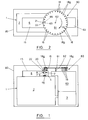
spectrophotometer unit 1 for analysis of a sample material by reflectance measurements from a beam of near infrared light that is applied to the sample. Theunit 1 is, conveniently, predominantly comprised of a generally known spectrophotometer unit, for example that as sold under the Trade Mark MODEL 6500 by NIR Systems Inc. Such a known spectrophotometer has amonochromator part 2 which is usually coupled to a computer 3 (not normally regarded as part of the spectrophotometer) from which it receives commands and transmits data back for analysis purposes. The function of themonochromator 2 is well known in the art and includes a generator 4a providing monochromatic nearinfrared light 4 which it presents through aslit 5. Coupled to themonochromator 2 and forming part of the spectrophotometer is areflectance module 6 into which the nearinfrared light 4 is presented from theslit 5. Conventionally included in themodule 6 are sensors ordetectors 7 which are responsive to near infrared light and when subjected to such light transmit signals to themonochromator 2 and therethrough data to thecomputer 3 for analysis measurements to be effected. Light 4 from theslit 5 is directed as a beam through a flatquartz sheet window 8 in abase plate 15 of themodule 6 onto a sample material for spectrophotometric analysis located at ascanning station 20. Theplate 15 is opaque and non-reflective to near infrared light. This sample material is housed in avial 16 which is located adjacent to thewindow 8 externally of themodule 6 so that light reflected from the sample material re-enters themodule 6 through thewindow 8 to be picked up by thedetectors 7 for effecting the analysis. - The apparatus shown is primarily intended for spectrophotometric analysis of pharmaceutical samples where a sample may be available only in a small quantity. Such samples P in powder form are housed within conventional pharmaceutical thin
walled glass vials 16 each having a flatcircular base 17 and an open toppedcylindrical side wall 18 upstanding from the base to be concentric therewith and closed by a cap or stopper 18a. Avial 16 is located at thescanning station 20 on themodule 6 so that itscircular base 17 fully overlies acircular aperture 13 in theplate 15 which aperture is bridged by thewindow 8. For the purpose of locating avial 16 correctly for analysis measurements its base stands on theplate 15 slidably accommodated in a complementaryannular seating 21 presented on thebase plate 15 adjacent to itsaperture 13. From Figure 3 it will be seen that the diameter of theaperture 13 is considerably less than the diameter of thevial base 17 and is also less than the internal diameter of the vial at itsbase 17. Consequently when thevial base 17 is located on theseating 21 to be concentric with theaperture 13, the marginal periphery of the vial base which includes the junction between that base and the side wall 18 (which junction is illustrated at 23 in Figures 3 and 4) does not overlie theaperture 13 and is therefore remote from theincident beam 4. A conventional pharmaceutical vial will have a base diameter not greater than 20 millimetres and a thickness for its cylindrical wall not greater than 2 millimetres, typically the vial base diameter will be 15 millimetres, the cylindrical wall thickness will be 0.5 millimetres and the vial will have a capacity in the order of 4.0 ccs. With such a typical vial theaperture 13 may have a diameter of, say, 12 millimetres. - The
beam 4 is directed substantially vertically and theplate 15 is disposed in a horizontal plane. Avial 16 located at thestation 20 with itsbase 17 horizontal and standing on theplate 15 in theseating 21 will have its sample powder P dispersed uniformly on thevial base 17 to extend fully over and beyond the whole periphery of theaperture 13. As a consequence thebeam 4 directed through theaperture 13 will be applied to the powder P forlight 25 reflected therefrom to be applied to thedetectors 7 for spectrophotometric analysis in conventional manner. In particular, it will be noted that the periphery of the vial base which includes thejunction 23 between that base and thecylindrical side wall 18 is covered by thebase plate 15 to the extent that the base plate prevents light from being applied directly to thejunction 23 from thebeam 4. This alleviates spurious or stray light reflections which could otherwise emanate from the wall/base junction 23 of the vial from adversely affecting the accuracy of the spectrophotometric measurements. - The
annular seating 21 is conveniently defined on thebase plate 15 by anannular seating plate 22 located in anannular recess 22a in theplate 15. It will be appreciated thatdifferent seating plates 22 can be applied to the plate 15 (such different seating plates having different diameter seatings 21 for accommodating and locating differently sized vials 16). Also by having theseating plate 22 removable, a reference standard material (for example "Spectralon" - Trade Mark) may be fitted directly over theaperture 13 for the purpose of providing a standard approximately 99% reflective surface to the near infrared light from thebeam 4 in setting up the spectrophotometer prior to carrying out an analysis measurement. Theseating plate 22 presents a substantially frustoconical guide surface 22b which is concentric with theaperture 13 and converges to theseating 21. Theguide surface 22b provides a lead-in over which a vial may slide to assist in location of thebase 17 of the vial concentrically on theseating 21. - It will be seen from Figure 3 that the
base 17 of avial 16 in theseating 21 at thestation 20 stands on and is in face-to-face contact with thebase plate 15 so that thebeam 4 immediately enters the base of the vial from theaperture 13. Furthermore, the base plate 15 (which will usually be formed of metal) serves to protect the outer surface of thewindow 8 from being damaged, for example scratched, by contact with the vial base. -
Vials 16 from an array thereof and each containing sample material P are fed successively and automatically to thescanning station 20 for spectrophotometric analysis of the respective samples and removed from the station following such measurement. For this purpose the apparatus includes an endless conveyor which, in the present example, is in the form of acarousel 60 comprising a substantially horizontalcircular disc 61 centrally mounted for rotation on avertical shaft 62 which is coupled to be rotated by adrive unit 63. - The
vials 16 containing the samples for analysis are disposed in a circumferentially spaced array at the marginal peripheral edge part of the disc 61 (as best seen in Figure 2). Each vial is received as a free sliding fit in anaperture 61a in thedisc 16 and is suspended from the disc by abutment of itscap 18a with the upper surface of the disc. For convenience not all of the suspendedvials 16 have been shown in Figure 1. Thedrive unit 63 is controlled automatically by thecomputer 3 in synchronisation with actuation of thespectrophotometer 1 to rotate theshaft 62 and thereby index thedisc 61 intermittently to feed thevials 16 successively to theannular vial seating 21 on theplate 15. In the embodiment shown in Figure 3 theseating 21 is disposed betweenramps annular seating plate 22 carried by thebase plate 15. Theramps ramps disc 61 is rotated, thebase 17 of a vial approaching thestation 20 will abut and slide over the leadingramp 65 causing that vial to be displaced vertically upwardly relative to thedisc 61 so that it is no longer suspended by itscap 18a from that disc. Further rotation of the carousel displaces the vial from the leadingramp 65 and down the frustoconical guide surface 22b to theseating 21 so that the vial is displaced downwardly under gravity to stand on theplate 15 in theseating 21 which determines the location of thevial base 17 concentric with theaperture 13. In this condition of the vial and with the carousel stationary, the spectrophotometer is actuated by the computer control to effect the analysis measurements. Following such measurements thedisc 61 is further rotated to urge thevial 16 on theseating 21 into abutment with theguide surface 22b leading to the trailingramp 66. Thesurface 22b to theramp 66 causes the vial to be raised from theseating 21 and as the vial slides over that ramp clear of thestation 20, it eventually drops relative to thedisc 61 to be suspended therefrom by itscap 18a. The automatic intermittent rotation of thedisc 61 under control of thecomputer 3 ensures that the feed or indexing of thevials 16 to theseating 21 is synchronised with the analysis measurements which are effected on the vial that is stationary on theseating 21. - In the modification shown in Figure 4 the
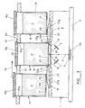
disc 61 of thecarousel 60 rotates about its vertical axis to index the suspendedvials 16 in a relatively high plane (as indicated by the broken lines in the Figure). When a particular vial has been indexed to a position in which it directly overlies theseating 21, thedisc 61 is displaced vertically downwardly along its axis of rotation to a low plane to deposit thatparticular vial 16 on the seating 21 (as indicated by the full lines in Figure 4). As thedisc 61 is lowered for thevial 16 to stand directly on theplate 15 in theseating 21, the cap of that vial may be moved clear of the disc 61 (by the vial's abutment with the plate 15) whilst the vial remains retained in theaperture 61a so that the vial stands alone on the seating, possibly being centralised on theseating 21 by the frustoconical guide surface 22b. It will be seen from Figure 4 that during lowering of thedisc 61, the twovials 16 which are adjacent to and on each side of thevial 16 that is in theseating 21 abut theunit 1 to be raised relative to thedisc 61 but this is incidental. With thedisc 61 in the low plane and the carousel stationary, the spectrophotometer is actuated by the computer control to effect the analysis measurements of the powder in the vial on the seating. Thereafter thedisc 61 is raised to its high plane, again to suspend therefrom all of thevials 16 which it carries so that they are clear of theunit 1 and thedisc 61 can then be rotatably indexed to locate afurther vial 16 over theseating 21. - The
drive unit 63 for rotatably indexing thevials 16 on the carousel will typically have an electrical stepper motor controlled by optical switches which determine the desired stop motion positions to locate a selected vial over theseating 21 under computer control. In the modification of Figure 4, vertical displacement of therotation shaft 62 for thedisc 61 to move the disc between its high and low planes whilst indexing is conveniently effected by a further electrical drive motor controlled by limit switches. - Desirably the
station 20 together with the carousel andvials 16 carried thereby are enclosed within anopaque cover 80.
Claims (24)
- Apparatus for spectrophotometric analysis of a material by reflectance measurements resulting from a beam of electromagnetic radiation applied to the material which comprises a station at which a container housing the material is to be located for said measurements and means for carrying an array of said containers and feeding each container successively to locate it at said station for spectrophotometric measurements and removing the respective container from the station following said measurement; said means for carrying, feeding and removing the array of containers comprising an endless conveyor, intermittent displacement of which feeds each container successively to the station, retains the respective container stationary at the station for spectrophotometric measurement and displaces to remove the respective container from the station following measurement; and wherein the station comprises a seating to which a said container is fed to be accommodated and retained in a predetermined position for said measurement, said seating coinciding with an aperture in a plate that is opaque and substantially non-reflective to the electromagnetic radiation and through which aperture the beam is applied to the material and the reflectance measurements are detected.
- Apparatus as claimed in claim 1 in which said seating is carried by said plate.
- Apparatus as claimed in either claim 1 or claim 2 in which a sheet material window translucent to said beam is disposed between the seating and a source for said beam for said beam to be directed through the window to the material housed in the container.
- Apparatus as claimed in any one of the preceding claims in which the feed and removal of the containers is controlled automatically by a computer programmed to effect said spectrophotometric measurement.
- Apparatus as claimed in any one of the preceding claims in which the conveyor comprises a carousel intermittently rotatable to effect said displacement.
- Apparatus as claimed in claim 5 in which the carousel is intermittently rotatable about an upstanding axis and is indexible for locating a predetermined container over said seating and is displaceable in the direction of its axis of rotation to lower the predetermined container on to the seating for said measurement and to raise the predetermined container from the seating for further indexing of the containers.
- Apparatus as claimed in either claim 5 or claim 6 in which the carousel comprises a rotatable disc from which said containers are to be suspended to be carried thereby in an array spaced about the periphery of the disc.
- Apparatus as claimed in any one of the preceding claims and comprising an opaque cover enclosing the station together with the means for carrying the array of containers and containers when carried thereby.
- Apparatus as claimed in any one of the preceding claims and comprising a guide surface associated with said seating and with which a container on the conveyor may abut, the guide surface serving to provide a lead-in for the container as it is fed to the seating to assist in location of the container at the seating.
- Apparatus as claimed in any one of the preceding claims in combination with an array of containers within each of which material for analysis is accommodated.
- Apparatus as claimed in claim 10 in which said carrying, feed and removal means locates a container at the station for the material in the container to fully overlie the aperture in the plate and extend beyond the periphery of that aperture.
- Apparatus as claimed in claim 11 in which the container has a substantially flat wall part which fully overlies the aperture and extends beyond the periphery of that aperture and through which wall part the beam is directed to the material dispersed over that wall part.
- Apparatus as claimed in claim 12 in which the wall part is in abutment with the plate to overlie the aperture therein.
- Apparatus as claimed in claim 13 when appendant to claim 3 in which the plate protects the window from abutment by the container.
- Apparatus as claimed in any one of claims 10 to 14 in which each container of the array is a vial having a substantially circular flat base and a substantially cylindrical side wall extending concentrically from said base and said beam is directed to the material in the vial through the flat base.
- Apparatus as claimed in claim 15 in which the seating is circular for the circular base of the vial to be received thereby as a substantially complementary fit.
- Apparatus as claimed in either claim 15 or claim 16 in which the base of a said vial accommodated by the seating fully overlies the aperture of the plate so that the periphery of the base comprising its junction with the cylindrical side wall is located wholly outside the periphery of the aperture of the plate and the beam is applied to the material in the vial through the vial base other than at a position through the vial base at its junction with the side wall.
- Apparatus as claimed in any one of claims 15 to 17 in which the vial has a base diameter not greater than 20 millimetres and a wall thickness not greater than 2 millimetres.
- Apparatus as claimed in any one of claims 15 to 18 in which the circular base of a vial accommodated by the seating is substantially concentric with the aperture in the plate.
- Apparatus as claimed in any one of claims 15 to 19 when appendant to claim 9 in which the guide surface is substantially frusto conical and converges to the seating to provide a lead-in for the circular base of a container to that seating.
- Apparatus as claimed in any one of the preceding claims in which the beam is directed substantially vertically.
- Apparatus as claimed in claim 21 in which the station is directed upwardly and the containers are carried by the conveyor over the station and each container is controlled to be deposited downwardly onto the station for the spectrophotometric measurements and raised from said station subsequent to said measurements.
- Apparatus as claimed in any one of the preceding claims in which the seating is on the plate.
- A computer when programmed to control the feed and removal of the containers in the array for spectrophotometric measurement with the apparatus of claim 4.
Priority Applications (1)
| Application Number | Priority Date | Filing Date | Title |
|---|---|---|---|
| US08/857,922 US5969813A (en) | 1997-04-17 | 1998-02-12 | Vial autosampler |
Applications Claiming Priority (2)
| Application Number | Priority Date | Filing Date | Title |
|---|---|---|---|
| GB9610317A GB2313192B (en) | 1996-05-17 | 1996-05-17 | Vial autosampler |
| GB9610317 | 1996-05-17 |
Publications (2)
| Publication Number | Publication Date |
|---|---|
| EP0807810A1 true EP0807810A1 (en) | 1997-11-19 |
| EP0807810B1 EP0807810B1 (en) | 2000-11-02 |
Family
ID=10793850
Family Applications (1)
| Application Number | Title | Priority Date | Filing Date |
|---|---|---|---|
| EP97302641A Expired - Lifetime EP0807810B1 (en) | 1996-05-17 | 1997-04-17 | Vial autosampler |
Country Status (10)
| Country | Link |
|---|---|
| EP (1) | EP0807810B1 (en) |
| JP (1) | JP3207370B2 (en) |
| AT (1) | ATE197348T1 (en) |
| CA (1) | CA2204311C (en) |
| DE (1) | DE69703410T2 (en) |
| DK (1) | DK0807810T3 (en) |
| ES (1) | ES2151704T3 (en) |
| GB (1) | GB2313192B (en) |
| GR (1) | GR3035266T3 (en) |
| PT (1) | PT807810E (en) |
Cited By (3)
| Publication number | Priority date | Publication date | Assignee | Title |
|---|---|---|---|---|
| USRE38986E1 (en) * | 1998-09-01 | 2006-02-21 | X-Rite, Incorporated | Portable scanning spectrophotometer |
| CN112243498A (en) * | 2018-06-04 | 2021-01-19 | 株式会社日立高新技术 | Connection device and sample inspection automation system provided with same |
| CN114371248A (en) * | 2020-10-16 | 2022-04-19 | 株式会社岛津制作所 | Automatic sample injection system |
Families Citing this family (4)
| Publication number | Priority date | Publication date | Assignee | Title |
|---|---|---|---|---|
| CA2046371A1 (en) * | 1990-07-13 | 1992-01-14 | Elaine A. Mertzel | Polymeric/polyimide compositions having enhanced electrostatic dissipation |
| JP4547801B2 (en) * | 2000-12-26 | 2010-09-22 | 株式会社島津製作所 | Autosampler |
| ES2199080B1 (en) * | 2002-07-16 | 2005-02-16 | Universidad Politecnica De Valencia | ROTARY SUPPORT AND APPARATUS FOR SPECTROSCOPIC MULTIPLE CHARACTERIZATION OF SAMPLES OF SOLID MATERIALS. |
| CN107271366B (en) * | 2017-06-28 | 2020-01-17 | 中南民族大学 | Colorimetric bottle/tube for detecting nitrophenol |
Citations (6)
| Publication number | Priority date | Publication date | Assignee | Title |
|---|---|---|---|---|
| US3322958A (en) * | 1964-05-07 | 1967-05-30 | American Instr Co Inc | Photometer automatic sample changer |
| EP0068717A2 (en) * | 1981-06-18 | 1983-01-05 | Coulter Electronics, Limited | Apparatus for monitoring chemical reactions |
| EP0303175A2 (en) * | 1987-08-04 | 1989-02-15 | Kanebo, Ltd. | Inspection equipment |
| EP0388168A2 (en) * | 1989-03-16 | 1990-09-19 | Johnson & Johnson Clinical Diagnostics, Inc. | Incubator |
| WO1991008463A2 (en) * | 1989-11-22 | 1991-06-13 | Vettest, S.A. | Chemical analyzer |
| GB2292798A (en) * | 1994-08-26 | 1996-03-06 | Merck & Co Inc | Determining the homogeneity of a mixture |
Family Cites Families (8)
| Publication number | Priority date | Publication date | Assignee | Title |
|---|---|---|---|---|
| JPS51108887A (en) * | 1975-03-20 | 1976-09-27 | Nippon Electron Optics Lab | Jidokagakubunsekisochi |
| GB1515947A (en) * | 1975-06-11 | 1978-06-28 | Beadle Ltd B | Buoyancy aids |
| JPS55144550A (en) * | 1979-04-28 | 1980-11-11 | Olympus Optical Co Ltd | Automatic analyzer |
| US4346056A (en) * | 1979-08-15 | 1982-08-24 | Olympus Optical Company Limited | Automatic analyzing apparatus |
| DE3175289D1 (en) * | 1980-05-30 | 1986-10-16 | Hitachi Ltd | Method for operating an apparatus for analysing samples optically |
| JPS57156543A (en) * | 1981-03-24 | 1982-09-27 | Olympus Optical Co Ltd | Device for chemical analysis |
| US4933147A (en) * | 1985-07-15 | 1990-06-12 | Abbott Laboratories | Unitized reagent containment system for clinical analyzer |
| JP2731229B2 (en) * | 1989-04-25 | 1998-03-25 | オリンパス光学工業株式会社 | Automatic analyzer |
-
1996
- 1996-05-17 GB GB9610317A patent/GB2313192B/en not_active Revoked
-
1997
- 1997-04-17 EP EP97302641A patent/EP0807810B1/en not_active Expired - Lifetime
- 1997-04-17 DK DK97302641T patent/DK0807810T3/en active
- 1997-04-17 ES ES97302641T patent/ES2151704T3/en not_active Expired - Lifetime
- 1997-04-17 AT AT97302641T patent/ATE197348T1/en not_active IP Right Cessation
- 1997-04-17 PT PT97302641T patent/PT807810E/en unknown
- 1997-04-17 DE DE69703410T patent/DE69703410T2/en not_active Expired - Fee Related
- 1997-05-02 CA CA002204311A patent/CA2204311C/en not_active Expired - Fee Related
- 1997-05-15 JP JP12524597A patent/JP3207370B2/en not_active Expired - Fee Related
-
2001
- 2001-01-17 GR GR20010400086T patent/GR3035266T3/en not_active IP Right Cessation
Patent Citations (6)
| Publication number | Priority date | Publication date | Assignee | Title |
|---|---|---|---|---|
| US3322958A (en) * | 1964-05-07 | 1967-05-30 | American Instr Co Inc | Photometer automatic sample changer |
| EP0068717A2 (en) * | 1981-06-18 | 1983-01-05 | Coulter Electronics, Limited | Apparatus for monitoring chemical reactions |
| EP0303175A2 (en) * | 1987-08-04 | 1989-02-15 | Kanebo, Ltd. | Inspection equipment |
| EP0388168A2 (en) * | 1989-03-16 | 1990-09-19 | Johnson & Johnson Clinical Diagnostics, Inc. | Incubator |
| WO1991008463A2 (en) * | 1989-11-22 | 1991-06-13 | Vettest, S.A. | Chemical analyzer |
| GB2292798A (en) * | 1994-08-26 | 1996-03-06 | Merck & Co Inc | Determining the homogeneity of a mixture |
Cited By (5)
| Publication number | Priority date | Publication date | Assignee | Title |
|---|---|---|---|---|
| USRE38986E1 (en) * | 1998-09-01 | 2006-02-21 | X-Rite, Incorporated | Portable scanning spectrophotometer |
| CN112243498A (en) * | 2018-06-04 | 2021-01-19 | 株式会社日立高新技术 | Connection device and sample inspection automation system provided with same |
| EP3805766A4 (en) * | 2018-06-04 | 2022-03-09 | Hitachi High-Tech Corporation | Connection device and specimen inspection automating system provided with same |
| CN114371248A (en) * | 2020-10-16 | 2022-04-19 | 株式会社岛津制作所 | Automatic sample injection system |
| CN114371248B (en) * | 2020-10-16 | 2024-03-19 | 株式会社岛津制作所 | Automatic sample injection system |
Also Published As
| Publication number | Publication date |
|---|---|
| DE69703410T2 (en) | 2001-04-26 |
| EP0807810B1 (en) | 2000-11-02 |
| CA2204311A1 (en) | 1997-11-17 |
| GR3035266T3 (en) | 2001-04-30 |
| DK0807810T3 (en) | 2001-02-26 |
| GB9610317D0 (en) | 1996-07-24 |
| ATE197348T1 (en) | 2000-11-15 |
| GB2313192A (en) | 1997-11-19 |
| DE69703410D1 (en) | 2000-12-07 |
| JPH1062343A (en) | 1998-03-06 |
| ES2151704T3 (en) | 2001-01-01 |
| GB2313192B (en) | 1999-12-22 |
| JP3207370B2 (en) | 2001-09-10 |
| PT807810E (en) | 2001-03-30 |
| CA2204311C (en) | 2002-02-05 |
Similar Documents
| Publication | Publication Date | Title |
|---|---|---|
| CA2204302C (en) | Spectrophotometric analysis | |
| CA1292627C (en) | Luminometer construction | |
| US4224032A (en) | Method and apparatus for chemical analysis | |
| US4808380A (en) | Automatic chemical analyzing apparatus | |
| EP0035320B1 (en) | Sample feeding system | |
| CA1099951A (en) | Automatic chemical analysis of biological fluids | |
| EP0216026B1 (en) | Automatic analysis apparatus | |
| US4906433A (en) | Automatic chemical analyzer | |
| US4512952A (en) | Apparatus for storing and dispensing analysis slides | |
| JP3967785B2 (en) | Near-infrared transmission spectrum measuring device and instrument for measuring near-infrared transmission of tablets | |
| US5496519A (en) | Diagnostic processing station | |
| JPH04357460A (en) | System and method for analyzing slide, slide moving apparatus, slide and cartridge for slide | |
| CA2204311C (en) | Vial autosampler | |
| US4090791A (en) | Device for cyclically repeating a series of colorimetric analysis on each of a succession of samples | |
| US3704953A (en) | Automatic radiant energy analyzer with programmed sample selection and analysis | |
| JPH01219669A (en) | Detecting method of liquid sample vessel according to assortment | |
| JPS5845888B2 (en) | Chemical reaction monitoring method and apparatus | |
| US4412742A (en) | Apparatus for use in investigating specimens | |
| US5969813A (en) | Vial autosampler | |
| US4539645A (en) | Automated sample analyzer for induction furnace analysis | |
| JP2003521707A (en) | Apparatus and method for analysis | |
| EP1480751B1 (en) | Method and sampling device for detection of low levels of a property/quality trait present in an inhomogeneously distributed sample substrate | |
| EP0047612A1 (en) | Apparatus for detecting flaws in internal coatings on moving open-mouth containers | |
| JPH02269969A (en) | Liquid sample analysis apparatus | |
| US11226349B2 (en) | Automated monochromator sample feeding mechanism |
Legal Events
| Date | Code | Title | Description |
|---|---|---|---|
| PUAI | Public reference made under article 153(3) epc to a published international application that has entered the european phase |
Free format text: ORIGINAL CODE: 0009012 |
|
| AK | Designated contracting states |
Kind code of ref document: A1 Designated state(s): AT BE CH DE DK ES FI FR GB GR IE IT LI LU NL PT SE |
|
| 17P | Request for examination filed |
Effective date: 19971215 |
|
| 17Q | First examination report despatched |
Effective date: 19980225 |
|
| GRAG | Despatch of communication of intention to grant |
Free format text: ORIGINAL CODE: EPIDOS AGRA |
|
| GRAG | Despatch of communication of intention to grant |
Free format text: ORIGINAL CODE: EPIDOS AGRA |
|
| 17Q | First examination report despatched |
Effective date: 19980225 |
|
| GRAG | Despatch of communication of intention to grant |
Free format text: ORIGINAL CODE: EPIDOS AGRA |
|
| GRAH | Despatch of communication of intention to grant a patent |
Free format text: ORIGINAL CODE: EPIDOS IGRA |
|
| GRAH | Despatch of communication of intention to grant a patent |
Free format text: ORIGINAL CODE: EPIDOS IGRA |
|
| GRAA | (expected) grant |
Free format text: ORIGINAL CODE: 0009210 |
|
| RAP1 | Party data changed (applicant data changed or rights of an application transferred) |
Owner name: PFIZER LIMITED Owner name: PFIZER INC. |
|
| AK | Designated contracting states |
Kind code of ref document: B1 Designated state(s): AT BE CH DE DK ES FI FR GB GR IE IT LI LU NL PT SE |
|
| REF | Corresponds to: |
Ref document number: 197348 Country of ref document: AT Date of ref document: 20001115 Kind code of ref document: T |
|
| REG | Reference to a national code |
Ref country code: CH Ref legal event code: EP |
|
| REF | Corresponds to: |
Ref document number: 69703410 Country of ref document: DE Date of ref document: 20001207 |
|
| REG | Reference to a national code |
Ref country code: IE Ref legal event code: FG4D |
|
| ITF | It: translation for a ep patent filed |
Owner name: MODIANO & ASSOCIATI S.R.L. |
|
| REG | Reference to a national code |
Ref country code: ES Ref legal event code: FG2A Ref document number: 2151704 Country of ref document: ES Kind code of ref document: T3 |
|
| ET | Fr: translation filed | ||
| REG | Reference to a national code |
Ref country code: CH Ref legal event code: NV Representative=s name: E. BLUM & CO. PATENTANWAELTE |
|
| REG | Reference to a national code |
Ref country code: DK Ref legal event code: T3 |
|
| REG | Reference to a national code |
Ref country code: PT Ref legal event code: SC4A Free format text: AVAILABILITY OF NATIONAL TRANSLATION Effective date: 20001218 |
|
| PLBE | No opposition filed within time limit |
Free format text: ORIGINAL CODE: 0009261 |
|
| STAA | Information on the status of an ep patent application or granted ep patent |
Free format text: STATUS: NO OPPOSITION FILED WITHIN TIME LIMIT |
|
| 26N | No opposition filed | ||
| REG | Reference to a national code |
Ref country code: GB Ref legal event code: IF02 |
|
| PGFP | Annual fee paid to national office [announced via postgrant information from national office to epo] |
Ref country code: GB Payment date: 20030313 Year of fee payment: 7 Ref country code: AT Payment date: 20030313 Year of fee payment: 7 |
|
| PGFP | Annual fee paid to national office [announced via postgrant information from national office to epo] |
Ref country code: DK Payment date: 20030314 Year of fee payment: 7 |
|
| PGFP | Annual fee paid to national office [announced via postgrant information from national office to epo] |
Ref country code: NL Payment date: 20030318 Year of fee payment: 7 |
|
| PGFP | Annual fee paid to national office [announced via postgrant information from national office to epo] |
Ref country code: LU Payment date: 20030331 Year of fee payment: 7 |
|
| PGFP | Annual fee paid to national office [announced via postgrant information from national office to epo] |
Ref country code: FR Payment date: 20030403 Year of fee payment: 7 |
|
| PGFP | Annual fee paid to national office [announced via postgrant information from national office to epo] |
Ref country code: SE Payment date: 20030407 Year of fee payment: 7 |
|
| PGFP | Annual fee paid to national office [announced via postgrant information from national office to epo] |
Ref country code: FI Payment date: 20030411 Year of fee payment: 7 |
|
| PGFP | Annual fee paid to national office [announced via postgrant information from national office to epo] |
Ref country code: IE Payment date: 20030417 Year of fee payment: 7 |
|
| PGFP | Annual fee paid to national office [announced via postgrant information from national office to epo] |
Ref country code: GR Payment date: 20030422 Year of fee payment: 7 |
|
| PGFP | Annual fee paid to national office [announced via postgrant information from national office to epo] |
Ref country code: PT Payment date: 20030424 Year of fee payment: 7 |
|
| PGFP | Annual fee paid to national office [announced via postgrant information from national office to epo] |
Ref country code: ES Payment date: 20030428 Year of fee payment: 7 |
|
| PGFP | Annual fee paid to national office [announced via postgrant information from national office to epo] |
Ref country code: DE Payment date: 20030430 Year of fee payment: 7 |
|
| PGFP | Annual fee paid to national office [announced via postgrant information from national office to epo] |
Ref country code: BE Payment date: 20030514 Year of fee payment: 7 |
|
| PGFP | Annual fee paid to national office [announced via postgrant information from national office to epo] |
Ref country code: CH Payment date: 20030605 Year of fee payment: 7 |
|
| PG25 | Lapsed in a contracting state [announced via postgrant information from national office to epo] |
Ref country code: LU Free format text: LAPSE BECAUSE OF NON-PAYMENT OF DUE FEES Effective date: 20040417 Ref country code: GB Free format text: LAPSE BECAUSE OF NON-PAYMENT OF DUE FEES Effective date: 20040417 Ref country code: FI Free format text: LAPSE BECAUSE OF NON-PAYMENT OF DUE FEES Effective date: 20040417 Ref country code: AT Free format text: LAPSE BECAUSE OF NON-PAYMENT OF DUE FEES Effective date: 20040417 |
|
| PG25 | Lapsed in a contracting state [announced via postgrant information from national office to epo] |
Ref country code: SE Free format text: LAPSE BECAUSE OF NON-PAYMENT OF DUE FEES Effective date: 20040418 |
|
| PG25 | Lapsed in a contracting state [announced via postgrant information from national office to epo] |
Ref country code: IE Free format text: LAPSE BECAUSE OF NON-PAYMENT OF DUE FEES Effective date: 20040419 Ref country code: ES Free format text: LAPSE BECAUSE OF NON-PAYMENT OF DUE FEES Effective date: 20040419 |
|
| PG25 | Lapsed in a contracting state [announced via postgrant information from national office to epo] |
Ref country code: LI Free format text: LAPSE BECAUSE OF NON-PAYMENT OF DUE FEES Effective date: 20040430 Ref country code: DK Free format text: LAPSE BECAUSE OF NON-PAYMENT OF DUE FEES Effective date: 20040430 Ref country code: CH Free format text: LAPSE BECAUSE OF NON-PAYMENT OF DUE FEES Effective date: 20040430 Ref country code: BE Free format text: LAPSE BECAUSE OF NON-PAYMENT OF DUE FEES Effective date: 20040430 |
|
| PG25 | Lapsed in a contracting state [announced via postgrant information from national office to epo] |
Ref country code: PT Free format text: LAPSE BECAUSE OF NON-PAYMENT OF DUE FEES Effective date: 20041018 |
|
| BERE | Be: lapsed |
Owner name: *PFIZER INC. Effective date: 20040430 |
|
| PG25 | Lapsed in a contracting state [announced via postgrant information from national office to epo] |
Ref country code: NL Free format text: LAPSE BECAUSE OF NON-PAYMENT OF DUE FEES Effective date: 20041101 |
|
| PG25 | Lapsed in a contracting state [announced via postgrant information from national office to epo] |
Ref country code: GR Free format text: LAPSE BECAUSE OF NON-PAYMENT OF DUE FEES Effective date: 20041103 Ref country code: DE Free format text: LAPSE BECAUSE OF NON-PAYMENT OF DUE FEES Effective date: 20041103 |
|
| EUG | Se: european patent has lapsed | ||
| GBPC | Gb: european patent ceased through non-payment of renewal fee |
Effective date: 20040417 |
|
| REG | Reference to a national code |
Ref country code: CH Ref legal event code: PL |
|
| PG25 | Lapsed in a contracting state [announced via postgrant information from national office to epo] |
Ref country code: FR Free format text: LAPSE BECAUSE OF NON-PAYMENT OF DUE FEES Effective date: 20041231 |
|
| REG | Reference to a national code |
Ref country code: PT Ref legal event code: MM4A Free format text: LAPSE DUE TO NON-PAYMENT OF FEES Effective date: 20041018 |
|
| NLV4 | Nl: lapsed or anulled due to non-payment of the annual fee |
Effective date: 20041101 |
|
| REG | Reference to a national code |
Ref country code: IE Ref legal event code: MM4A |
|
| REG | Reference to a national code |
Ref country code: FR Ref legal event code: ST |
|
| PG25 | Lapsed in a contracting state [announced via postgrant information from national office to epo] |
Ref country code: IT Free format text: LAPSE BECAUSE OF NON-PAYMENT OF DUE FEES;WARNING: LAPSES OF ITALIAN PATENTS WITH EFFECTIVE DATE BEFORE 2007 MAY HAVE OCCURRED AT ANY TIME BEFORE 2007. THE CORRECT EFFECTIVE DATE MAY BE DIFFERENT FROM THE ONE RECORDED. Effective date: 20050417 |
|
| REG | Reference to a national code |
Ref country code: ES Ref legal event code: FD2A Effective date: 20040419 |