EP0807927A2 - Disc reproducing method and apparatus - Google Patents
Disc reproducing method and apparatus Download PDFInfo
- Publication number
- EP0807927A2 EP0807927A2 EP97303044A EP97303044A EP0807927A2 EP 0807927 A2 EP0807927 A2 EP 0807927A2 EP 97303044 A EP97303044 A EP 97303044A EP 97303044 A EP97303044 A EP 97303044A EP 0807927 A2 EP0807927 A2 EP 0807927A2
- Authority
- EP
- European Patent Office
- Prior art keywords
- disc
- data area
- data
- track
- reproducing
- Prior art date
- Legal status (The legal status is an assumption and is not a legal conclusion. Google has not performed a legal analysis and makes no representation as to the accuracy of the status listed.)
- Ceased
Links
Images


Classifications
-
- G—PHYSICS
- G11—INFORMATION STORAGE
- G11B—INFORMATION STORAGE BASED ON RELATIVE MOVEMENT BETWEEN RECORD CARRIER AND TRANSDUCER
- G11B20/00—Signal processing not specific to the method of recording or reproducing; Circuits therefor
- G11B20/10—Digital recording or reproducing
- G11B20/12—Formatting, e.g. arrangement of data block or words on the record carriers
- G11B20/1217—Formatting, e.g. arrangement of data block or words on the record carriers on discs
- G11B20/1258—Formatting, e.g. arrangement of data block or words on the record carriers on discs where blocks are arranged within multiple radial zones, e.g. Zone Bit Recording or Constant Density Recording discs, MCAV discs, MCLV discs
-
- G—PHYSICS
- G11—INFORMATION STORAGE
- G11B—INFORMATION STORAGE BASED ON RELATIVE MOVEMENT BETWEEN RECORD CARRIER AND TRANSDUCER
- G11B19/00—Driving, starting, stopping record carriers not specifically of filamentary or web form, or of supports therefor; Control thereof; Control of operating function ; Driving both disc and head
- G11B19/20—Driving; Starting; Stopping; Control thereof
- G11B19/26—Speed-changing arrangements; Reversing arrangements; Drive-transfer means therefor
-
- G—PHYSICS
- G11—INFORMATION STORAGE
- G11B—INFORMATION STORAGE BASED ON RELATIVE MOVEMENT BETWEEN RECORD CARRIER AND TRANSDUCER
- G11B7/00—Recording or reproducing by optical means, e.g. recording using a thermal beam of optical radiation by modifying optical properties or the physical structure, reproducing using an optical beam at lower power by sensing optical properties; Record carriers therefor
- G11B7/002—Recording, reproducing or erasing systems characterised by the shape or form of the carrier
- G11B7/0037—Recording, reproducing or erasing systems characterised by the shape or form of the carrier with discs
-
- G—PHYSICS
- G11—INFORMATION STORAGE
- G11B—INFORMATION STORAGE BASED ON RELATIVE MOVEMENT BETWEEN RECORD CARRIER AND TRANSDUCER
- G11B7/00—Recording or reproducing by optical means, e.g. recording using a thermal beam of optical radiation by modifying optical properties or the physical structure, reproducing using an optical beam at lower power by sensing optical properties; Record carriers therefor
- G11B7/007—Arrangement of the information on the record carrier, e.g. form of tracks, actual track shape, e.g. wobbled, or cross-section, e.g. v-shaped; Sequential information structures, e.g. sectoring or header formats within a track
- G11B7/0079—Zoned data area, e.g. having different data structures or formats for the user data within data layer, Zone Constant Linear Velocity [ZCLV], Zone Constant Angular Velocity [ZCAV], carriers with RAM and ROM areas
-
- G—PHYSICS
- G11—INFORMATION STORAGE
- G11B—INFORMATION STORAGE BASED ON RELATIVE MOVEMENT BETWEEN RECORD CARRIER AND TRANSDUCER
- G11B7/00—Recording or reproducing by optical means, e.g. recording using a thermal beam of optical radiation by modifying optical properties or the physical structure, reproducing using an optical beam at lower power by sensing optical properties; Record carriers therefor
- G11B7/004—Recording, reproducing or erasing methods; Read, write or erase circuits therefor
- G11B7/005—Reproducing
Definitions
- CD-ROM drives have been developed for use in computer peripheral equipment, which are capable of high-speed reproduction, such as a quadruple-speed reproduction, an octuple-speed reproduction and further a decuple-speed reproduction.
- the rotation speed of the disc motor varies according to the radial position of the currently read track of the disc to decrease in inverse proportion to the radial position of the track. Accordingly, at the time of track jump operation, if a normal rotation speed for a target track significantly differs from the rotation speed in the currently reading operation, the motor speed must be greatly changed. As a result, a relatively long time is needed to reach the normal rotation speed.
- a disc motor having an enhanced acceleration/deceleration performance may be used.
- a disc motor having the enhanced acceleration/deceleration performance largely impedes the realisation of small-sized and cheap CD-ROM drives.
- a CD-ROM drive adapted for such high-speed reproduction is mounted in a small portable information handling equipment, users may feel unpleasant mechanical vibration occurring in the CD-ROM drive due to the high speed rotation of the disc motor.
- a CAV (Constant Angular Velocity) system reproduction is used for discs on which signals are recorded at the CLV system.
- the rotation speed of a disc motor is constant at all track positions on a disc, it is unnecessary to employ a disc motor which has an enhanced acceleration/deceleration performance.
- the data reproduction rate varies over wide range between the innermost track and the outermost track of the disc.
- the reproduction rate of data on the outer track is higher than the reproduction rate of data on the inner track. Accordingly, if a motor is rotated at a high speed in order to achieve the high-speed reproduction, a data processing circuit is required to have a much higher data processing capacity.
- the oscillation frequency of a clock generator which defines the performance of a data processing circuit, the improvement in reproduction speed of a disc reproducing apparatus is also limited.
- the present invention seeks to provide an improved disc reproducing method and a disc reproducing apparatus, in particular, which is capable of reducing the size and the cost of the apparatus by reducing a burden on a disc motor and the mechanical vibration occurring therefrom by lowering the maximum rotation speed of a disc motor in the high speed reproduction.
- a disc reproducing method for reproducing data stored on a disc comprising the steps of: reading data at a constant angular velocity from an inner data area of the disc at a smaller radius than a boundary radius, and reading data at a constant linear velocity system from an outer data area of the disc at a larger radius than a boundary radius.
- the reading of data for the inner data area is carried out at a constant angular velocity.
- a sufficient data rate is achieved with a rotation speed relatively lower than the rotation speed of the disc motor required in reproducing data in the inner data area at a constant linear velocity.
- a disc reproducing method may also include the step of reading of data from the inner data area at a CAV system with a specified angular velocity which corresponds to the CLV system rotation speed for reading the specific track.
- a disc reproducing apparatus for reproducing data stored on a disc, comprising:
- control means may control the rotation speed to be a constant rotation speed defined in accordance with a radial position of the given track dividing the data area on the disc into the two areas.
- the disc reproducing apparatus may read data from the inner data area at a CAV system with a specified angular velocity which corresponds to the CLV system rotation speed for reading the specific track.
- the mode change between the CAV system for the inner area and the CLV system for the outer data area is smoothly carried out. Further, the data rate of the signal read from the inner data area at the CAV system is assured to fall within a range of data processing capacity.
- the disc reproducing apparatus for reproducing data stored on a disc may additionally include a disc motor for rotating a disc, and an FG pulse detecting means for detecting FG pulses generated from the disc motor, wherein the determining means determines to which area the position of the currently reading track belongs based on the FG pulses detected by the FG pulse detecting means and a frame synchronizing signal reproduced from the disc.
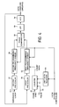
- FIG. 1 shows a block diagram for illustrating the configuration of a CD-ROM reproducing apparatus according to a preferred embodiment of the present invention.
- signals read from a disc 2 by an optical pickup 1 are supplied to an RF amplifier 3.
- the RF amplifier 3 extracts a focus error signal and a tracking error signal 4 from an RF signal 7 output from the optical pickup 1.
- the RF amplifier 3 then provides the focus error signal and the tracking error signal 4 to a focus tracking controller 5 and also provide the RF signal 7 to a level slicer PLL 6.
- the focus tracking controller 5 generates a lens control signal from the focus error signal and the tracking error signal 4 supplied from the RF amplifier 3 and supplies the lens control signal to the optical pickup 1.
- a feed motor controller 8 generates a driving signal 13 from the tracking error signal component supplied from the focus tracking controller 5, a pulse signal 10 varying in proportion to the rotation of a feed motor 9 detected from the feed motor 9 and a search instruction signal 12 supplied from a system controller 11, and provides the driving signal 13 to the feed motor 9.
- the level slicer PLL 6 generates an EFM signal by binarizing the RF signal, and also generates a PLL-based clock 14 in synchronizm with the EFM signal for use in reading the EFM signal.
- a binary EFM signal 15 is supplied to a CD signal processor 16. Further, the PLL-based clock 14 is supplied to both the CD signal processor 16 and a selector 17.
- the CD signal processor 16 detects a CD sync signal by using the PLL-base clock 14 and performs a data extraction and an EFM demodulation based on the detected CD sync signal. Then, the CD signal processor 16 extracts only a subcode data 18 from the demodulated data and supplies the subcode data 18 to the system controller 11.
- the CD signal processor 16 also stores another data, i.e., a main data in a RAM 19 under the control of the PLL-based clock 14. Furthermore, the CD signal processor 16 reads data out of the RAM 19 under the control of clocks supplied through the selector 17 and then performs a correction process on the read data.
- a detected CD frame sync signal 22 is supplied to a CAV/CLV motor controller 23. On the other hand, the corrected data is supplied to an interpolator 25 or a CD-ROM signal processor 26 via a selector 24.
- the selector 17 is switched by an AUDIO-CD/CD-ROM switching instruction signal 27 which is output from the system controller 11.
- an AUDIO-CD is addressed by the instruction signal 27, the selector 17 selects a x'tal based clock 21a which is output from a clock generator 20.
- the selector 17 selects the PLL-based clock 14 which is output from the level slicer PLL 6 through a production signal path and supplies it to the CD signal processor 16.
- the selector 24 is also switched according to the AUDIO-CD/CD-ROM switching instruction signal 27 which is output from the system controller 11.
- the selector 24 supplies data to the interpolator 25 when the AUDIO-CD is addressed by the instruction signal 27 and supplies data to the CD-ROM signal processor 26 when the CD-ROM is addressed.
- the interpolator 25 interpolates data only when data is marked with an error flag and supplies the interpolated data to a D/A converter 28.
- the D/A converter 28 converts data from digital to analog and outputs as the reproduced audio signal through an LPF (low-pass filter).
- the CD-ROM signal processor 26 executes a CD-ROM sync detection from CD-ROM data, a CD-ROM data descrambling, a correction of CD-ROM data, a write/read control of data to/from a buffer memory 29.
- the CD-ROM sync detection and the CD-ROM data descrambling are performed under the control of a clock supplied from the selector 17.
- the data correction process and the write/read control of data to/from the buffer memory 29 are performed under the control of a clock 21b supplied from the clock generator 20.
- the data read out from the buffer memory 29 is transferred to a host computer, which is an external equipment, through an interface controller 30. Further, the CD-ROM signal processor 26 supplies a HEADER data 31 which is an address of CD-ROM data to the system controller 11.
- the interface controller 30 executes interfaces,such as communication of operating instructions and data,with a host computer.
- the operating instructions are communicated between the system controller 11 and the host computer via the interface controller 30.
- the CAV/CLV motor controller 23 generates a control signal 35 based on the AUDIO-CD/CD-ROM switching instruction signal 27 supplied from the system controller 11, the PLL system frame sync signal 22 supplied from the CD signal processor 16, a transmission system clock 21c supplied from the clock generator 20 and an FG pulse 34 which is the output of an FG pulse detector 32 for detecting the rotation speed of a disc motor 36 and supplies the control signal 35 to the disc motor 36.
- the CAV/CLV motor controller 23 controls the CLV system when the instruction signal 27 for addressing the AUDIO-CD is input from the system controller 11. That is, in this case, the CAV/CLV motor controller 23 compares a reference signal, i.e., a fixed divided frequency of the X'tal-based clock 21a which is output from the clock generator 20 with the PLL system frame sync signal 22, and generates the control signal 35 corresponding to an error resulted from the comparison. Further, the CAV/CLV motor controller 23 selects either the CAV system or the CLV system when the instruction signal 27 for addressing the CD-ROM is input from the system controller 11.
- a reference signal i.e., a fixed divided frequency of the X'tal-based clock 21a which is output from the clock generator 20 with the PLL system frame sync signal 22
- the CAV/CLV motor controller 23 selects either the CAV system or the CLV system when the instruction signal 27 for addressing the CD-ROM is input from the system controller 11.
- the system controller 11 controls the overall operations of the CD-ROM including a search, ON/OFF operations for a variety of circuits. Furthermore, the system controller 11 determines whether the main data is an AUDIO-CD data or a CD-ROM data based on a subcode data demodulated in the CD signal processor 16 and outputs the AUDIO-CD/CD-ROM switching instruction signal 27 to the selectors 17 and 24 for instructing a standard-speed reproduction at the CLV in case of AUDIO-CD data, or a reproduction at the CAV system or the CLV system in case of the CD-ROM data.
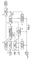
- FIG. 2 shows a block diagram of the CAV/CLV motor controller 23.
- control sections associated with the AUDIO-CD/CD-ROM switching instruction signal 27 from the system controller 11 are omitted.
- the FG pulse 34 supplied from the FG pulse detector 32 and the frame sync signal 22 supplied from the CD signal processor 16 are input to a first counter 41.
- the frame sync signal 22 has a frequency of 7.35 kHz at the time of standard-speed CLV system reproduction.
- the first counter 41 counts the frame sync signals 22 during one FG pulse cycle. Further, the first counter 41 has a function to compare its counted value with a limit value which is preset in a limit data register 43 and if a count value is larger than a limit value, the count value is output to a programmable frequency divider 42 and if a count value is less than a limit value, the limit value is output to the programmable frequency divider 42.
- the system clock 21c is input to a first pre-scaler 44 and a second pre-scaler 45.
- the system clock 21c is 16.9344 MHz.
- the programmable frequency divider 42 further divides the frequency-divided clock supplied from the first pre-scaler 44 by the count value of the first counter 41 and outputs the divided clock to a second counter 47.
- the FG pulse 34 supplied from the FG pulse detector 32 is input to an n-th frequency divider 48.
- the n-th frequency divider 48 divides the FG pulse 34 by a multi-speed reproduction factor n at the CLV system and outputs the divided frequency to the second counter 47.
- the second counter 47 counts the output clocks of the programmable frequency divider 42 in one cycle of the n-th division FG pulse and outputs the count value to the PWM modulator 46.
- this second counter 47 is comprised of a down counter having such a preset value that an output count value becomes zero when the disc motor 36 is rotating at a specified rotation speed associated with a track position.
- the PWM modulator 46 generates motor driving voltage to be supplied to the disc motor 36 from the divided clock from the second pre-scaler 45 and the output value of the second counter 47. That is, a duty ratio of the motor driving voltage is controlled based on the output value of the second counter 47 using the divided clock from the second pre-scaler 45 as a motor driving voltage frequency to be generated.
- a limit value in the limit data register 43 and the divisor value n of the n-th frequency divider 48 are defined by the system controller 11.
- a time for one disc rotation at a track position is expressed by (2 ⁇ R)/(LV ⁇ n), where R is a distance from the center of a disc at an applicable track position, LV is a linear velocity rotation of data recorded on the disc, and n is a multi-speed reproduction factor.
- the number of frame sync signals in one cycle of FG pulse at the applicable track position which is the output of the first counter 41 will be ((2 ⁇ R)/LV) ⁇ 7350 ⁇ (1/FG), where FG is the number of FG pulses per a rotation of the disc motor.
- the output frequency of the programmable frequency divider 42 to divide the output of the first pre-scaler 44 using the output of the first counter 41 as a frequency divided value will be fs ⁇ (1/P1) ⁇ ((LV ⁇ FG)/(2 ⁇ 7350)), where fs is system clock frequency and P1 is the divided frequency of the first pre-scaler.
- the number of frame sync signals for one cycle of FG pulse is constant for each track position. So, the system clock frequency obtained by dividing system clock divided by a fixed frequency dividing value P1 which is further divided by the number of frame sync signals for one cycle of FG pulse will take a value reflecting the track position (regardless of the rotation speed of the disc motor).
- the number of output clocks of the programmable frequency divider 42 for one cycle of the FG pulse output from the second counter 47 is constant at any track position.
- the FG pulse cycle is (2 ⁇ R)/(LV ⁇ n ⁇ FG) and the cycle after dividing FG pulse by the n-th frequency divider 48 is (2 ⁇ R)/(LV ⁇ FG).
- fs 16.9344 and P1 is 9, and so
- the number of output clocks of the programmable frequency divider 42 in one cycle after n-th division of FG pulse will become 256. This value will become constant if the disc motor 36 rotate at a specified rotation speed associated with a track position, regardless of the position of currently reading track, the normal linear velocity value of the recorded data of a disc and the number of FG pulses during one rotation of the disc motor.
- the number of output clocks of the second counter 47 departs from a specific value 256 by an error.
- the PWM modulator 46 generates motor control voltage (having a constant frequency) of a duty ratio associated with the output of the second counter 47 and applies it to the disc motor 36.
- the CLV control of the disc motor 36 is carried out.
- the second counter 47 is comprised of a down counter having a preset value of 256 which is reset for every cycle of the output of the n-th frequency divider 48.
- the down counter counts down by 1 for every pulse applied from the programmable frequency divider 42 after reset, and outputs a count-down value immediately before every reset to the PWM modulator 46.
- the operation described above is called as a proportional control.
- a proportional control if an error in the rotation speed of the disc motor 36 from the target rotation speed is eliminated, an acceleration or a deceleration to the disc motor 36 is removed.
- the disc motor 36 actually maintains the rotation at an almost constant speed equal to or slightly lower than a target rotation speed at a state where the lead-in operation to the target rotation speed is completed. That is, the output count value of the second counter, i.e., the down counter 47 will become a slightly larger than zero (0), after the completion of the lead-in operation to the target speed of the disc motor 36.
- the CD-ROM reproducing apparatus in this embodiment is so configured that the output count value of the second counter 47 after the lead-in operation to the target speed of the disc motor 36 is completed is set into an offset data register 49 as an offset data and then a preset value of the second counter 47 is offset by the offset data value.
- the output count value of the second counter 47 is prevented from falling into the zero. Accordingly, the driving electric power corresponding at least to the offset data value is supplied to the disc motor 36.
- the setting of the offset data into the offset data register 49 can be made through the system controller 11. Or the output count value of the second counter 47 after the completion of the preceding lead-in operation of the rotation speed may be taken into the offset data register 49.
- the first counter 41 for counting the frame sync signals 22 during one cycle of the FG pulse is so configured that it compares its output count value with a limit value which is preset in the limit data register 43, and then provides the count value to the programmable frequency divider 42 if the count value is larger than the limit value while provides the limit value to the programmable frequency divider 42 if the count value is less than the limit value.
- the number of frame sync signals 22 during one cycle of FG pulse is expressed by [(2 ⁇ R)/LV] ⁇ 7350.
- R a distance of current track from the disc center
- the current reading position is located further out than the track position specified by the limit value, while if the count value of the first counter 41 is less than the limit value the current reading position is located further in than the track position specified by the limit value.
- the CLV control for the disc motor 36 as described above is executed when the current reading position is located on the outer side of the disc from the track position specified by the limit value, as shown in FIG. 3.
- the limit value is provided to the programmmable frequency divider 42 as the output of the first counter 41, in place of the count value.
- the limit value has a constant value, as long as the reading position is located further in than the track position specified by the limit value, the disc motor 36 rotates at a constant rotation speed associated with the limit value. Thus the CAV control for the disc motor 36 is executed.
- the reproduction of the outer data area of the disc bordered by the track position specified by the limit value is carried out using the CLV system, while the reproduction of the inner data area of the disc is carried out using the CAV system. Then, it is possible to reduce the maximum rotation speed in the reproduction of the inner data area by executing the reproduction of the inner data area of the disc at the CAV system where it was apt to increase at the CLV system in the known apparatus. Accordingly, the burden of the disc motor 36 is also significantly reduced. As a result, it becomes possible to reduce the dependency on the disc motor performance in achieving the high-speed reproduction and to realize the reduction of size and the lowering of weight in the disc motor and also the reduction of size and the lowering of cost in the apparatus.
- the CAV system reproduction is executed only in the inner data area of the disc.
- the rotation speed in the inner data area is carried out at a constant linear velocity defined for the specific bordering track which divides the data area of the disc into the inner data area and the outer data area. Accordingly, it is assured that the reproduction signal rate for the reproduction of the inner data area of the disc at the CAV system falls within a range of data processing capacity.
- FIG.4 shows an example of the circuit arrangement to perform the variable control of system clock frequency to be applied to this CAV/CLV motor controller and the data processor
- a counter 51 receives the FG pulse 34 from the FG pulse detector 32 and the frame sync signal 22 from the CD signal processor 16 , and then counts the frame sync signals 22 during one cycle of FG pulse.
- the counter 51 compares its count value with a limit value which is preset in a limit data register 53, and supplies a count value to a first programmable frequency divider 52 if the count value is higher than the limit value (in case of the outer data area of a disc), while supplies the limit value to the first programmable frequency divider 52 if the count value is lower than the limit value (in case of the inner data area of a disc).
- the first programmable frequency divider 52 further divides the oscillation frequency of a VCO 54 which is previously divided by a first pre-scaler 55 by a counter value of the counter 51, and outputs the divided oscillation frequency to a phase comparator 58.
- the phase comparator 58 detects a phase difference between the output signal of this first programmable frequency divider 52 and the output of a second programmable frequency divider 56, that is, a signal obtained by dividing the reference system clock 21c by a second pre-scalar 57, and further dividing it by a preset value of the system controller 11, and provides the resulting error signal to the VCO 54 via an LPF 59.
- a fixed limit value is preset into the programmable frequency divider 52.
- a phase difference between the output signal of this first programmable frequency divider 52 and the output signal of the second programmable frequency divider 56 is stable at a value close to zero.
- the oscillation frequency of the VCO 54 that is, the frequency of the system clock 21c to be applied to the CAV/CLV motor controller and the data processor is kept constant. As a result, it becomes possible to execute the reproduction of the outer data area of a disc at the CLV system bordering at a track position which is specified by the limit value.
- a count value of the counter 51 which is lower than the limit value is preset to the first programmable frequency divider 52. Then, a phase difference corresponding to the difference between the limit value and the count value occurs between the outputs of the programmable frequency dividers 52 and 56. This phase difference is detected by a phase comparator 58 and then supplied to the VCO 54 via the LPF 59 as an error signal. Therefore, the oscillation frequency of the VCO 54, that is, the frequency of the system clock 21c to be applied to the CAV/CLV motor controller 23 and the data processor lowers when the current reading track on the disc approaches the innermost track of the disc from the track specified by the limit value. Thus, it becomes possible to execute the reproduction of the inner data area of the disc at the CAV system.
- the present invention can provide an extremely preferable disc reproducing method and a disc reproducing apparatus.
- the disc reproducing method and the disc reproducing apparatus according to the present invention can execute the reproduction of the inner data area of the disc where data are recorded at a very high rotation speed at the CLV (Constant Linear Velocity) system at the CAV (Constant Angular Velocity) system.
- CLV Constant Linear Velocity
- CAV Constant Angular Velocity
- the inner data area divided from the outer data area by the specific track is read at a CAV system with a specified angular velocity which corresponds to the CLV system rotation speed for reading the specific track.
Abstract
Description
- In recent years, CD-ROM drives have been developed for use in computer peripheral equipment, which are capable of high-speed reproduction, such as a quadruple-speed reproduction, an octuple-speed reproduction and further a decuple-speed reproduction. In an apparatus capable of high-speed reproduction of discs on which signals are recorded using a CLV (Constant Linear Velocity) system, the rotation speed of the disc motor varies according to the radial position of the currently read track of the disc to decrease in inverse proportion to the radial position of the track. Accordingly, at the time of track jump operation, if a normal rotation speed for a target track significantly differs from the rotation speed in the currently reading operation, the motor speed must be greatly changed. As a result, a relatively long time is needed to reach the normal rotation speed.
- To reduce an average access time for a track jump operation, a disc motor having an enhanced acceleration/deceleration performance, and thus is capable of producing a high torque, may be used. However, such a disc motor having the enhanced acceleration/deceleration performance largely impedes the realisation of small-sized and cheap CD-ROM drives. Further, if such a CD-ROM drive adapted for such high-speed reproduction is mounted in a small portable information handling equipment, users may feel unpleasant mechanical vibration occurring in the CD-ROM drive due to the high speed rotation of the disc motor.
- As another approach of achieving the high-speed reproduction without relation to the performance of disc motors, a CAV (Constant Angular Velocity) system reproduction is used for discs on which signals are recorded at the CLV system. In this approach, as the rotation speed of a disc motor is constant at all track positions on a disc, it is unnecessary to employ a disc motor which has an enhanced acceleration/deceleration performance.
- In this case, however, the data reproduction rate varies over wide range between the innermost track and the outermost track of the disc. In more detail, the reproduction rate of data on the outer track is higher than the reproduction rate of data on the inner track. Accordingly, if a motor is rotated at a high speed in order to achieve the high-speed reproduction, a data processing circuit is required to have a much higher data processing capacity. However, because there is an upper limitation to the oscillation frequency of a clock generator which defines the performance of a data processing circuit, the improvement in reproduction speed of a disc reproducing apparatus is also limited.
- In known disc reproducing apparatus such as CD-ROMs, the necessity of high performance disc motors was a stumbling block against a miniaturization, a weight-reduction and a cost-reduction of the apparatus. In addition, the mechanical vibration occurring in the apparatus when a disc motor is driven at high speed for the high-speed reproduction was also a significant problem.
- The present invention seeks to provide an improved disc reproducing method and a disc reproducing apparatus, in particular, which is capable of reducing the size and the cost of the apparatus by reducing a burden on a disc motor and the mechanical vibration occurring therefrom by lowering the maximum rotation speed of a disc motor in the high speed reproduction.
- According to a first aspect of the present invention, there is provided a disc reproducing method for reproducing data stored on a disc comprising the steps of:
reading data at a constant angular velocity from an inner data area of the disc at a smaller radius than a boundary radius, and reading data at a constant linear velocity system from an outer data area of the disc at a larger radius than a boundary radius. - In accordance with this method, the reading of data for the inner data area is carried out at a constant angular velocity. Thus, a sufficient data rate is achieved with a rotation speed relatively lower than the rotation speed of the disc motor required in reproducing data in the inner data area at a constant linear velocity. Thus it is possible to reduce a burden of the disc motor and the mechanical vibration occurring due to the higher speed rotation of the disc motor.
- A disc reproducing method may also include the step of reading of data from the inner data area at a CAV system with a specified angular velocity which corresponds to the CLV system rotation speed for reading the specific track. In this way, the mode change between the CAV system for the inner area and the CLV system for the outer data area is smoothly carried out and, furthermore, the data rate of the signal read from the inner data area at the CAV system is assured to fall within a range of data processing capacity.
- According to a second aspect of the present invention, there is provided a disc reproducing apparatus for reproducing data stored on a disc, comprising:
- setting means for setting information for dividing the data area of a disc into an inner data area and an outer data area divided at a boundary radius;
- determining means for determining to which area the current track belongs; and
- control means for controlling the apparatus so as to read data at a constant linear velocity if the determined position of the current track belongs to the outer data area of the disc, and to read data at a constant angular velocity if the determined position of the current track is in the inner data area of a disc.
- In the disc reproducing apparatus of the present invention the control means may control the rotation speed to be a constant rotation speed defined in accordance with a radial position of the given track dividing the data area on the disc into the two areas.
- Accordingly, it is possible to lower the maximum rotation speed of a disc motor and so to reduce the burden on the disc motor and the mechanical vibration occurring due to the higher speed rotation of the disc motor. Further, the disc reproducing apparatus may read data from the inner data area at a CAV system with a specified angular velocity which corresponds to the CLV system rotation speed for reading the specific track. The mode change between the CAV system for the inner area and the CLV system for the outer data area is smoothly carried out. Further, the data rate of the signal read from the inner data area at the CAV system is assured to fall within a range of data processing capacity.
- The disc reproducing apparatus for reproducing data stored on a disc may additionally include a disc motor for rotating a disc, and an FG pulse detecting means for detecting FG pulses generated from the disc motor, wherein the determining means determines to which area the position of the currently reading track belongs based on the FG pulses detected by the FG pulse detecting means and a frame synchronizing signal reproduced from the disc.
- Accordingly, it is possible easily to design a hardware for the means of determining to which area the currently reading track belongs, together with the FG pulse detecting means. It becomes also possible easily to design a hardware for the all of or a part of the controlling means, once a hardware has been designed for the determining means.
- For a better understanding of the present invention and many of the attendant advantages thereof, reference will now be made by way of example to the accompanying drawings, wherein:
- FIG. 1 is a block diagram for illustrating the entire configuration of a CD-ROM reproducing apparatus according to a preferred embodiment of the present invention;
- FIG. 2 is a block diagram for illustrating the configuration of a CAV/CLV motor controller shown in FIG. 1;
- FIG. 3 is a diagram for illustrating the relationship of a track position on a disc to a rotation speed of a disc motor and a signal transfer rate; and
- FIG. 4 is a block diagram for illustrating the configuration of a variable controller of system clock frequency which is applied to a CAV/CLV motor controller and a data processor according to a preferred embodiment of the present invention.
- The present invention will be described in detail with reference to the FIGURES 1 through 4.
- FIG. 1 shows a block diagram for illustrating the configuration of a CD-ROM reproducing apparatus according to a preferred embodiment of the present invention.
- In FIGURE 1, signals read from a
disc 2 by an optical pickup 1 are supplied to an RF amplifier 3. The RF amplifier 3 extracts a focus error signal and a tracking error signal 4 from anRF signal 7 output from the optical pickup 1. The RF amplifier 3 then provides the focus error signal and the tracking error signal 4 to afocus tracking controller 5 and also provide theRF signal 7 to a level slicer PLL 6. Thefocus tracking controller 5 generates a lens control signal from the focus error signal and the tracking error signal 4 supplied from the RF amplifier 3 and supplies the lens control signal to the optical pickup 1. - A
feed motor controller 8 generates adriving signal 13 from the tracking error signal component supplied from thefocus tracking controller 5, apulse signal 10 varying in proportion to the rotation of afeed motor 9 detected from thefeed motor 9 and asearch instruction signal 12 supplied from asystem controller 11, and provides thedriving signal 13 to thefeed motor 9. - The level slicer PLL 6 generates an EFM signal by binarizing the RF signal, and also generates a PLL-based
clock 14 in synchronizm with the EFM signal for use in reading the EFM signal. Abinary EFM signal 15 is supplied to aCD signal processor 16. Further, the PLL-basedclock 14 is supplied to both theCD signal processor 16 and aselector 17. - The
CD signal processor 16 detects a CD sync signal by using the PLL-base clock 14 and performs a data extraction and an EFM demodulation based on the detected CD sync signal. Then, theCD signal processor 16 extracts only asubcode data 18 from the demodulated data and supplies thesubcode data 18 to thesystem controller 11. TheCD signal processor 16 also stores another data, i.e., a main data in aRAM 19 under the control of the PLL-basedclock 14. Furthermore, theCD signal processor 16 reads data out of theRAM 19 under the control of clocks supplied through theselector 17 and then performs a correction process on the read data. A detected CDframe sync signal 22 is supplied to a CAV/CLV motor controller 23. On the other hand, the corrected data is supplied to aninterpolator 25 or a CD-ROM signal processor 26 via aselector 24. - The
selector 17 is switched by an AUDIO-CD/CD-ROMswitching instruction signal 27 which is output from thesystem controller 11. When an AUDIO-CD is addressed by theinstruction signal 27, theselector 17 selects a x'tal basedclock 21a which is output from aclock generator 20. While, when a CD-ROM is addressed, theselector 17 selects the PLL-basedclock 14 which is output from the level slicer PLL 6 through a production signal path and supplies it to theCD signal processor 16. - The
selector 24 is also switched according to the AUDIO-CD/CD-ROMswitching instruction signal 27 which is output from thesystem controller 11. Theselector 24 supplies data to theinterpolator 25 when the AUDIO-CD is addressed by theinstruction signal 27 and supplies data to the CD-ROM signal processor 26 when the CD-ROM is addressed. Theinterpolator 25 interpolates data only when data is marked with an error flag and supplies the interpolated data to a D/A converter 28. The D/A converter 28 converts data from digital to analog and outputs as the reproduced audio signal through an LPF (low-pass filter). - The CD-
ROM signal processor 26 executes a CD-ROM sync detection from CD-ROM data, a CD-ROM data descrambling, a correction of CD-ROM data, a write/read control of data to/from abuffer memory 29. The CD-ROM sync detection and the CD-ROM data descrambling are performed under the control of a clock supplied from theselector 17. The data correction process and the write/read control of data to/from thebuffer memory 29 are performed under the control of aclock 21b supplied from theclock generator 20. The data read out from thebuffer memory 29 is transferred to a host computer, which is an external equipment, through aninterface controller 30. Further, the CD-ROM signal processor 26 supplies aHEADER data 31 which is an address of CD-ROM data to thesystem controller 11. - The
interface controller 30 executes interfaces,such as communication of operating instructions and data,with a host computer. The operating instructions are communicated between thesystem controller 11 and the host computer via theinterface controller 30. - The CAV/
CLV motor controller 23 generates acontrol signal 35 based on the AUDIO-CD/CD-ROMswitching instruction signal 27 supplied from thesystem controller 11, the PLL systemframe sync signal 22 supplied from theCD signal processor 16, atransmission system clock 21c supplied from theclock generator 20 and anFG pulse 34 which is the output of anFG pulse detector 32 for detecting the rotation speed of adisc motor 36 and supplies thecontrol signal 35 to thedisc motor 36. - The CAV/
CLV motor controller 23 controls the CLV system when theinstruction signal 27 for addressing the AUDIO-CD is input from thesystem controller 11. That is, in this case, the CAV/CLV motor controller 23 compares a reference signal, i.e., a fixed divided frequency of the X'tal-basedclock 21a which is output from theclock generator 20 with the PLL systemframe sync signal 22, and generates thecontrol signal 35 corresponding to an error resulted from the comparison. Further, the CAV/CLV motor controller 23 selects either the CAV system or the CLV system when theinstruction signal 27 for addressing the CD-ROM is input from thesystem controller 11. - The
system controller 11 controls the overall operations of the CD-ROM including a search, ON/OFF operations for a variety of circuits. Furthermore, thesystem controller 11 determines whether the main data is an AUDIO-CD data or a CD-ROM data based on a subcode data demodulated in theCD signal processor 16 and outputs the AUDIO-CD/CD-ROMswitching instruction signal 27 to theselectors - FIG. 2 shows a block diagram of the CAV/
CLV motor controller 23. In FIG. 2, control sections associated with the AUDIO-CD/CD-ROMswitching instruction signal 27 from thesystem controller 11 are omitted. - In the CAV/
CLV motor controller 23, theFG pulse 34 supplied from theFG pulse detector 32 and theframe sync signal 22 supplied from theCD signal processor 16 are input to afirst counter 41. In this example, theframe sync signal 22 has a frequency of 7.35 kHz at the time of standard-speed CLV system reproduction. Thefirst counter 41 counts the frame sync signals 22 during one FG pulse cycle. Further, thefirst counter 41 has a function to compare its counted value with a limit value which is preset in alimit data register 43 and if a count value is larger than a limit value, the count value is output to a programmable frequency divider 42 and if a count value is less than a limit value, the limit value is output to the programmable frequency divider 42. - On the other hand, the
system clock 21c is input to afirst pre-scaler 44 and asecond pre-scaler 45. In this example, thesystem clock 21c is 16.9344 MHz. Thefirst pre-scaler 44 divides theinput system clock 21c by P1 (e.g., P1 = 9) and outputs the divided system clock to the programmable frequency divider 42. Thesecond pre-scaler 45 divides thesystem clock 21c by P2 (e.g., P2 = 3) and outputs the divided system clock to aPWM modulator 46. The programmable frequency divider 42 further divides the frequency-divided clock supplied from thefirst pre-scaler 44 by the count value of thefirst counter 41 and outputs the divided clock to asecond counter 47. Further, theFG pulse 34 supplied from theFG pulse detector 32 is input to an n-th frequency divider 48. The n-th frequency divider 48 divides theFG pulse 34 by a multi-speed reproduction factor n at the CLV system and outputs the divided frequency to thesecond counter 47. - The
second counter 47 counts the output clocks of the programmable frequency divider 42 in one cycle of the n-th division FG pulse and outputs the count value to thePWM modulator 46. Definitely, thissecond counter 47 is comprised of a down counter having such a preset value that an output count value becomes zero when thedisc motor 36 is rotating at a specified rotation speed associated with a track position. - The
PWM modulator 46 generates motor driving voltage to be supplied to thedisc motor 36 from the divided clock from thesecond pre-scaler 45 and the output value of thesecond counter 47. That is, a duty ratio of the motor driving voltage is controlled based on the output value of thesecond counter 47 using the divided clock from thesecond pre-scaler 45 as a motor driving voltage frequency to be generated. - A limit value in the limit data register 43 and the divisor value n of the n-
th frequency divider 48 are defined by thesystem controller 11. - Next, the operation of the CAV/
CLV motor controller 23 will be explained. - A time for one disc rotation at a track position is expressed by (2πR)/(LV·n), where R is a distance from the center of a disc at an applicable track position, LV is a linear velocity rotation of data recorded on the disc, and n is a multi-speed reproduction factor.
- Further, the number of frame sync signals which are input within a time for one disc rotation is ((2πR)/(LV·n)·n·7350 = ((2πR)/LV)·7350, where 7350 is the number of frame sync signals per second at the standard-speed CLV system reproduction used in this exemplary embodiment.
- Accordingly, the number of frame sync signals in one cycle of FG pulse at the applicable track position, which is the output of the
first counter 41 will be ((2πR)/LV)·7350· (1/FG), where FG is the number of FG pulses per a rotation of the disc motor. - Therefore, the output frequency of the programmable frequency divider 42 to divide the output of the
first pre-scaler 44 using the output of thefirst counter 41 as a frequency divided value will be fs ·(1/P1)·((LV·FG)/(2π· 7350)), where fs is system clock frequency and P1 is the divided frequency of the first pre-scaler. - For a disc carrying signals recorded at the CLV system, the number of frame sync signals for one cycle of FG pulse is constant for each track position. So, the system clock frequency obtained by dividing system clock divided by a fixed frequency dividing value P1 which is further divided by the number of frame sync signals for one cycle of FG pulse will take a value reflecting the track position (regardless of the rotation speed of the disc motor).
- When the
disc motor 36 is rotating at a specified rotation speed associated with a track position in the CLV system reproduction, the number of output clocks of the programmable frequency divider 42 for one cycle of the FG pulse output from thesecond counter 47 is constant at any track position. - That is, the FG pulse cycle is (2πR)/(LV·n·FG) and the cycle after dividing FG pulse by the n-
th frequency divider 48 is (2πR)/(LV·FG). The number of output clocks of the programmable frequency divider 42 in this cycle is ((2π R)/(LV·FG))·fs·(1/P1)·((LV·FG)/(2πR·7350)) = fs·(1/P1)· (1/7350). In this embodiment, fs is 16.9344 and P1 is 9, and so - the number of output clocks of the programmable frequency divider 42 in one cycle after n-th division of FG pulse will become 256. This value will become constant if the
disc motor 36 rotate at a specified rotation speed associated with a track position, regardless of the position of currently reading track, the normal linear velocity value of the recorded data of a disc and the number of FG pulses during one rotation of the disc motor. - Accordingly, if there is an error between the rotation speed of the
disc motor 36 and a target rotation speed associated with the current track position, the number of output clocks of thesecond counter 47 departs from a specific value 256 by an error. For eliminating the error from the specific value 256, thePWM modulator 46 generates motor control voltage (having a constant frequency) of a duty ratio associated with the output of thesecond counter 47 and applies it to thedisc motor 36. Thus, the CLV control of thedisc motor 36 is carried out. - Further, the
second counter 47 is comprised of a down counter having a preset value of 256 which is reset for every cycle of the output of the n-th frequency divider 48. The down counter counts down by 1 for every pulse applied from the programmable frequency divider 42 after reset, and outputs a count-down value immediately before every reset to thePWM modulator 46. - The operation described above is called as a proportional control. In such a proportion control, if an error in the rotation speed of the
disc motor 36 from the target rotation speed is eliminated, an acceleration or a deceleration to thedisc motor 36 is removed. Thedisc motor 36 actually maintains the rotation at an almost constant speed equal to or slightly lower than a target rotation speed at a state where the lead-in operation to the target rotation speed is completed. That is, the output count value of the second counter, i.e., the down counter 47 will become a slightly larger than zero (0), after the completion of the lead-in operation to the target speed of thedisc motor 36. - The CD-ROM reproducing apparatus in this embodiment is so configured that the output count value of the
second counter 47 after the lead-in operation to the target speed of thedisc motor 36 is completed is set into an offsetdata register 49 as an offset data and then a preset value of thesecond counter 47 is offset by the offset data value. Thus, even when the error between the rotation speed of thedisc motor 36 and the target rotation speed is eliminated, the output count value of thesecond counter 47 is prevented from falling into the zero. Accordingly, the driving electric power corresponding at least to the offset data value is supplied to thedisc motor 36. Thus, it becomes possible to further reduce the error between the rotation speed of thedisc motor 36 and the target rotation speed after the lead-in operation of the rotation speed is completed. - Further, the setting of the offset data into the offset data register 49 can be made through the
system controller 11. Or the output count value of thesecond counter 47 after the completion of the preceding lead-in operation of the rotation speed may be taken into the offsetdata register 49. - Hereinafter, the switching between the CLV control and the CAV control of the disc motor in the CD-ROM reproducing apparatus will be explained.
- As described above, the
first counter 41 for counting the frame sync signals 22 during one cycle of the FG pulse is so configured that it compares its output count value with a limit value which is preset in the limit data register 43, and then provides the count value to the programmable frequency divider 42 if the count value is larger than the limit value while provides the limit value to the programmable frequency divider 42 if the count value is less than the limit value. - The number of frame sync signals 22 during one cycle of FG pulse is expressed by [(2πR)/LV]·7350. As the expression contains a factor of R (a distance of current track from the disc center) in the dividend, it is known that the number of the frame sync signals 22 has a relatively small value within the inner data area of a disc, while having a relatively large value within the outer data area of a disc.
- If the count value of the
first counter 41 is larger than the limit value the current reading position is located further out than the track position specified by the limit value, while if the count value of thefirst counter 41 is less than the limit value the current reading position is located further in than the track position specified by the limit value. - Accordingly, the CLV control for the
disc motor 36 as described above is executed when the current reading position is located on the outer side of the disc from the track position specified by the limit value, as shown in FIG. 3. - When the current reading position is located in the inner part of the disc relative the track position specified by the limit value, the limit value is provided to the programmmable frequency divider 42 as the output of the
first counter 41, in place of the count value. As the limit value has a constant value, as long as the reading position is located further in than the track position specified by the limit value, thedisc motor 36 rotates at a constant rotation speed associated with the limit value. Thus the CAV control for thedisc motor 36 is executed. - Thus, according to the CD-ROM reproducing apparatus in this embodiment, the reproduction of the outer data area of the disc bordered by the track position specified by the limit value is carried out using the CLV system, while the reproduction of the inner data area of the disc is carried out using the CAV system. Then, it is possible to reduce the maximum rotation speed in the reproduction of the inner data area by executing the reproduction of the inner data area of the disc at the CAV system where it was apt to increase at the CLV system in the known apparatus. Accordingly, the burden of the
disc motor 36 is also significantly reduced. As a result, it becomes possible to reduce the dependency on the disc motor performance in achieving the high-speed reproduction and to realize the reduction of size and the lowering of weight in the disc motor and also the reduction of size and the lowering of cost in the apparatus. - Further, in this CD-ROM reproducing apparatus, the CAV system reproduction is executed only in the inner data area of the disc. The rotation speed in the inner data area is carried out at a constant linear velocity defined for the specific bordering track which divides the data area of the disc into the inner data area and the outer data area.
Accordingly, it is assured that the reproduction signal rate for the reproduction of the inner data area of the disc at the CAV system falls within a range of data processing capacity. - Hereinafter, still another preferred embodiment of the present invention will be explained.
- When the frequency of the
system clock 21c to be applied to the CAV/CLV motor controller and the data processor varies in accordance with the track position by limiting the execution of the CAV system reproduction only to the inner data area of a disc, it becomes possible to reproduce the outer data area of a disc by the CLV system and reproduce the inner data area of a disc by the CAV system in a manner similar to the embodiment described above. - FIG.4 shows an example of the circuit arrangement to perform the variable control of system clock frequency to be applied to this CAV/CLV motor controller and the data processor
- A
counter 51 receives theFG pulse 34 from theFG pulse detector 32 and theframe sync signal 22 from theCD signal processor 16 , and then counts the frame sync signals 22 during one cycle of FG pulse. Thecounter 51 compares its count value with a limit value which is preset in alimit data register 53, and supplies a count value to a firstprogrammable frequency divider 52 if the count value is higher than the limit value (in case of the outer data area of a disc), while supplies the limit value to the firstprogrammable frequency divider 52 if the count value is lower than the limit value (in case of the inner data area of a disc). - The first
programmable frequency divider 52 further divides the oscillation frequency of aVCO 54 which is previously divided by afirst pre-scaler 55 by a counter value of thecounter 51, and outputs the divided oscillation frequency to aphase comparator 58. Thephase comparator 58 detects a phase difference between the output signal of this firstprogrammable frequency divider 52 and the output of a secondprogrammable frequency divider 56, that is, a signal obtained by dividing thereference system clock 21c by asecond pre-scalar 57, and further dividing it by a preset value of thesystem controller 11, and provides the resulting error signal to theVCO 54 via anLPF 59. - Now, if the reading position is in the outer data area of the disc, a fixed limit value is preset into the
programmable frequency divider 52. A phase difference between the output signal of this firstprogrammable frequency divider 52 and the output signal of the secondprogrammable frequency divider 56 is stable at a value close to zero. Thus, the oscillation frequency of theVCO 54, that is, the frequency of thesystem clock 21c to be applied to the CAV/CLV motor controller and the data processor is kept constant. As a result, it becomes possible to execute the reproduction of the outer data area of a disc at the CLV system bordering at a track position which is specified by the limit value. - Further, if the current reading track locates in the inner data area of a disc, a count value of the
counter 51 which is lower than the limit value is preset to the firstprogrammable frequency divider 52. Then, a phase difference corresponding to the difference between the limit value and the count value occurs between the outputs of theprogrammable frequency dividers phase comparator 58 and then supplied to theVCO 54 via theLPF 59 as an error signal. Therefore, the oscillation frequency of theVCO 54, that is, the frequency of thesystem clock 21c to be applied to the CAV/CLV motor controller 23 and the data processor lowers when the current reading track on the disc approaches the innermost track of the disc from the track specified by the limit value. Thus, it becomes possible to execute the reproduction of the inner data area of the disc at the CAV system. - As described above, the present invention can provide an extremely preferable disc reproducing method and a disc reproducing apparatus. The disc reproducing method and the disc reproducing apparatus according to the present invention can execute the reproduction of the inner data area of the disc where data are recorded at a very high rotation speed at the CLV (Constant Linear Velocity) system at the CAV (Constant Angular Velocity) system. Thus, it becomes possible to reduce the maximum rotation speed of the disc motor and a burden to the disc motor and mechanical vibration occurring thereby can be reduced.
- Further, according to the present invention, the inner data area divided from the outer data area by the specific track is read at a CAV system with a specified angular velocity which corresponds to the CLV system rotation speed for reading the specific track. Thus it is assured that the CAV system for reading the inner data area is smoothly changed to the CLV system for reading the outer and that the reproducing signal rate when reproducing the disc at the CAV system falls within the range of the data processing capacity.
- Furthermore, according to the present invention, it is possible to easily design a hardware for the means of determining which area the currently reading track belongs to, together with the FG pulse detecting means. It becomes also possible to easily design a hardware for the all of or a part of the controlling means, once a hardware has been designed for the determining means.
- While there have been illustrated and described what are at present considered to be preferred embodiments of the present invention, it will be understood by those skilled in the art that various changes and modifications may be made, and equivalents may be substituted for elements thereof without departing from the true scope of the present invention. In addition, many modifications may be made to adapt a particular situation or material to the teaching of the present invention without departing from the central scope thereof. Therefor, it is intended that the present invention not be limited to the particular embodiment disclosed as the best mode contemplated for carrying out the present invention, but that the present invention includes all embodiments falling within the scope of the appended claims.
- The foregoing description and the drawings are regarded by the applicant as including a variety of individually inventive concepts, some of which may lie partially or wholly outside the scope of some or all of the following claims. The fact that the applicant has chosen at the time of filing of the present application to restrict the claimed scope of protection in accordance with the following claims is not to be taken as a disclaimer or alternative inventive concepts that are included in the contents of the application and could be defined by claims differing in scope from the following claims, which different claims may be adopted subsequently during prosecution, for example, for the purposes of a divisional application.
Claims (10)
- A disc reproducing method for reproducing data stored on a disc comprising the steps of:
reading data at a constant angular velocity from an inner data area of the disc at a smaller radius than a boundary radius, and reading data at a constant linear velocity system from an outer data area of the disc at a larger radius than a boundary radius. - A disc reproducing method for reproducing data stored on a disc as claimed in claim 1, wherein the data is read from the inner data area at an angular velocity which corresponds to the CLV system rotation speed for reading a track at the boundary radius.
- A disc reproducing apparatus for reproducing data stored on a disc, comprising:setting means (43, 53) for setting information for dividing the data area of a disc into an inner data area and an outer data area divided at a boundary radius;determining means (41, 51) for determining to which area the current track belongs; andcontrol means (42, 52) for controlling the apparatus so as to read data at a constant linear velocity if the determined position of the current track belongs to the outer data area of the disc, and to read data at a constant angular velocity if the determined position of the current track is in the inner data area of a disc.
- A disc reproducing apparatus for reproducing data stored on a disc, as claimed in claim 3, wherein the data is read from the inner data area at an angular velocity which corresponds to the CLV system rotation speed for reading a track at the boundary radius.
- A disc reproducing apparatus for reproducing data stored on a disc as claimed in claim 3 or 4, further comprising:a disc motor (36) for driving the disc; andFG pulse detecting means (32) for detecting FG pulses generated from the disc motor (36);wherein the determining means (41, 51) determines to which area the position of the currently reading track belongs based on the FG pulses detected by the FG pulse detecting means and a frame synchronizing signal reproduced from the disc.
- A disc reproducing apparatus as claimed in one of claims 3-5, wherein the determining means (41, 51) determines to which area a track belongs by comparing a control value dependent on the radial position of the track or the data transfer rate with a limit value corresponding to the radial position of the boundary between the inner data area and the outer data area.
- A disc reproducing apparatus as claimed in claim 6, wherein control value is proportional to the radial position of the track, and the determining means (41, 51) outputs the control value if the control value is greater than the limit value, and outputs the limit value if the control value is less than the limit value, and the control means (42, 52) controls the speed of rotation of the disc in dependence on the output of the determining means (41, 51).
- A disc reproducing apparatus as claimed in claim 6, wherein the control value is proportional to the data transfer rate and the determining means outputs the control value if the control value is less than the limit value, and outputs the limit value if the control value is greater than the limit value and the control means (42, 52) controls the speed of rotation of the disc in dependence on the output of the determining means (41, 51).
- A disc reproducing method for reproducing a disc carrying signals recorded at a constant linear velocity rotation comprising the steps of:dividing a data area on a disc into an inner data area and an outer data area by a given track as a border; andreading data from the inner data area at a CAV system while reading data from the outer data area at a CLV system.
- A disc reproducing apparatus for reproducing a disc carrying signals recorded at a constant linear velocity rotation, comprising:setting means for setting information for dividing the data area of a disc at a given track as a border into an inner data area including the given track and an outer data area;determining means for determining which area the position of the currently reading track belongs to; andcontrol means for controlling the apparatus so as to read signals at a CLV system if the determined position of the currently reading track belongs to the outer data area of a disc divided based on the information set by the setting means, whilst to read signals at a CAV system if the determined position of the currently reading track belongs to the inner data area of a disc divided based on the information set by the setting means.
Applications Claiming Priority (2)
| Application Number | Priority Date | Filing Date | Title |
|---|---|---|---|
| JP117567/96 | 1996-05-13 | ||
| JP8117567A JPH09306092A (en) | 1996-05-13 | 1996-05-13 | Method for regenerating disk and device therefor |
Publications (2)
| Publication Number | Publication Date |
|---|---|
| EP0807927A2 true EP0807927A2 (en) | 1997-11-19 |
| EP0807927A3 EP0807927A3 (en) | 1998-07-01 |
Family
ID=14715018
Family Applications (1)
| Application Number | Title | Priority Date | Filing Date |
|---|---|---|---|
| EP97303044A Ceased EP0807927A3 (en) | 1996-05-13 | 1997-05-02 | Disc reproducing method and apparatus |
Country Status (4)
| Country | Link |
|---|---|
| US (1) | US6137757A (en) |
| EP (1) | EP0807927A3 (en) |
| JP (1) | JPH09306092A (en) |
| KR (1) | KR100300786B1 (en) |
Cited By (3)
| Publication number | Priority date | Publication date | Assignee | Title |
|---|---|---|---|---|
| EP0825601A2 (en) * | 1996-08-14 | 1998-02-25 | Sony Corporation | Disk driving system and disk driving method |
| EP0833328A2 (en) * | 1996-09-03 | 1998-04-01 | Pioneer Electronic Corporation | System for reading information recorded on a disc |
| WO1998027549A2 (en) * | 1996-12-19 | 1998-06-25 | Siemens Nixdorf Informationssysteme Ag | Cd-rom drive |
Families Citing this family (12)
| Publication number | Priority date | Publication date | Assignee | Title |
|---|---|---|---|---|
| US6870802B1 (en) * | 1999-05-27 | 2005-03-22 | Matsushita Electric Industrial Co., Ltd. | Information reproduction apparatus with selective CLV and CAV control |
| TW544669B (en) * | 2000-11-30 | 2003-08-01 | Via Tech Inc | Searching method and device for position of optical pick-up head |
| TWI277951B (en) * | 2001-06-15 | 2007-04-01 | Lite On It Corp | Method of dynamically adjusting the rotational speed for disk drive according to the amount of data transmission |
| US7403459B2 (en) * | 2002-01-22 | 2008-07-22 | Lite-On It Corp. | Rotational speed control method for a disk player |
| JP2003263760A (en) * | 2002-03-08 | 2003-09-19 | Toshiba Corp | Rotation corrective circuit, semiconductor integrated circuit, optical disk drive, and rotation corrective method |
| KR20030094700A (en) * | 2002-06-07 | 2003-12-18 | 주식회사 레인콤 | Multimedia Replaying Device for Reducing Influence of Shock |
| TW540802U (en) * | 2002-08-23 | 2003-07-01 | Lite On It Corp | CD drive using the earphone hole to input/output signal |
| US20060209640A1 (en) * | 2002-12-20 | 2006-09-21 | Koninklijke Philips Electronics N.V. | Method for dividing user storage space of an optical disc, optical disc having divided storage space, and method and device for storing information |
| JP3953036B2 (en) | 2004-02-24 | 2007-08-01 | ソニー株式会社 | Optical disc apparatus and photographing apparatus having the same |
| TWI259443B (en) | 2005-03-11 | 2006-08-01 | Lite On It Corp | Dynamic speed control method for storage device |
| US7355939B2 (en) * | 2006-08-11 | 2008-04-08 | Mediatek Inc. | System and method for switching control modes of spindle motor |
| JP4655110B2 (en) * | 2008-05-19 | 2011-03-23 | ソニー株式会社 | Optical disc apparatus and rotation control method |
Citations (6)
| Publication number | Priority date | Publication date | Assignee | Title |
|---|---|---|---|---|
| US4558375A (en) * | 1983-04-27 | 1985-12-10 | Sontheimer Carl Gustav | Method and apparatus for recording and retrieving video information in two modes on a single laser recording disc |
| JPS6199989A (en) * | 1984-10-19 | 1986-05-19 | Sony Corp | Disk recording and reproducing device |
| US5136560A (en) * | 1989-02-21 | 1992-08-04 | Pioneer Electronic Corporation | CAV/CLV composite disk accessing method utilizing different accessing procedures for respective CAV and CLV areas |
| US5425014A (en) * | 1991-07-25 | 1995-06-13 | Teac Corporation | Apparatus for constant angular velocity reading of constant linear velocity disks |
| US5446724A (en) * | 1991-06-28 | 1995-08-29 | Kabushiki Kaisha Toshiba | Information storage medium with first and second recording regions each having a predetermined recording density |
| JPH07235126A (en) * | 1994-02-24 | 1995-09-05 | Canon Inc | Electronic apparatus, system usint the same and control method therefor |
Family Cites Families (3)
| Publication number | Priority date | Publication date | Assignee | Title |
|---|---|---|---|---|
| JPS6196583A (en) * | 1984-10-17 | 1986-05-15 | Sony Corp | Disk recording and reproducing device |
| JPH07176141A (en) * | 1993-12-15 | 1995-07-14 | Nippon Columbia Co Ltd | Optical disk and optical disk recorder |
| KR0162374B1 (en) * | 1995-07-15 | 1998-12-15 | 구자홍 | Motor control method and device for disk reproduction |
-
1996
- 1996-05-13 JP JP8117567A patent/JPH09306092A/en active Pending
-
1997
- 1997-02-27 KR KR1019970006139A patent/KR100300786B1/en not_active IP Right Cessation
- 1997-03-06 US US08/812,041 patent/US6137757A/en not_active Expired - Fee Related
- 1997-05-02 EP EP97303044A patent/EP0807927A3/en not_active Ceased
Patent Citations (6)
| Publication number | Priority date | Publication date | Assignee | Title |
|---|---|---|---|---|
| US4558375A (en) * | 1983-04-27 | 1985-12-10 | Sontheimer Carl Gustav | Method and apparatus for recording and retrieving video information in two modes on a single laser recording disc |
| JPS6199989A (en) * | 1984-10-19 | 1986-05-19 | Sony Corp | Disk recording and reproducing device |
| US5136560A (en) * | 1989-02-21 | 1992-08-04 | Pioneer Electronic Corporation | CAV/CLV composite disk accessing method utilizing different accessing procedures for respective CAV and CLV areas |
| US5446724A (en) * | 1991-06-28 | 1995-08-29 | Kabushiki Kaisha Toshiba | Information storage medium with first and second recording regions each having a predetermined recording density |
| US5425014A (en) * | 1991-07-25 | 1995-06-13 | Teac Corporation | Apparatus for constant angular velocity reading of constant linear velocity disks |
| JPH07235126A (en) * | 1994-02-24 | 1995-09-05 | Canon Inc | Electronic apparatus, system usint the same and control method therefor |
Non-Patent Citations (2)
| Title |
|---|
| PATENT ABSTRACTS OF JAPAN vol. 010, no. 278 (P-499), 20 September 1986 & JP 61 099989 A (SONY CORP), 19 May 1986, * |
| PATENT ABSTRACTS OF JAPAN vol. 096, no. 001, 31 January 1996 & JP 07 235126 A (CANON INC), 5 September 1995, * |
Cited By (7)
| Publication number | Priority date | Publication date | Assignee | Title |
|---|---|---|---|---|
| EP0825601A2 (en) * | 1996-08-14 | 1998-02-25 | Sony Corporation | Disk driving system and disk driving method |
| EP0825601A3 (en) * | 1996-08-14 | 1998-11-11 | Sony Corporation | Disk driving system and disk driving method |
| EP0833328A2 (en) * | 1996-09-03 | 1998-04-01 | Pioneer Electronic Corporation | System for reading information recorded on a disc |
| EP0833328A3 (en) * | 1996-09-03 | 1998-11-11 | Pioneer Electronic Corporation | System for reading information recorded on a disc |
| WO1998027549A2 (en) * | 1996-12-19 | 1998-06-25 | Siemens Nixdorf Informationssysteme Ag | Cd-rom drive |
| WO1998027549A3 (en) * | 1996-12-19 | 1998-08-06 | Siemens Nixdorf Ag | Cd-rom drive |
| US6493300B2 (en) | 1996-12-19 | 2002-12-10 | Fujitsu Siemens Computers Gmbh | CD-ROM drive having adjustable multiple speed ranges |
Also Published As
| Publication number | Publication date |
|---|---|
| US6137757A (en) | 2000-10-24 |
| KR970076527A (en) | 1997-12-12 |
| JPH09306092A (en) | 1997-11-28 |
| EP0807927A3 (en) | 1998-07-01 |
| KR100300786B1 (en) | 2001-09-03 |
Similar Documents
| Publication | Publication Date | Title |
|---|---|---|
| US6137757A (en) | Disc reproducing method and apparatus for reproducing data from a disc using a CAV system and a CLV system | |
| US6529456B2 (en) | Disk reproducing device, a disk reproducing method, a disk rotation control method, and a regenerative clock signal generating device | |
| US5444687A (en) | Method and device for accessing an optical disc | |
| US5883866A (en) | Disk driving system and disk driving method | |
| JPH0845174A (en) | Optical disk reproducing device | |
| EP0622787B1 (en) | Disc recording/reproducing system | |
| EP0361944A1 (en) | Recorded data reading system | |
| EP0411961A2 (en) | Optical disk recording/reproducing device | |
| US5602812A (en) | Reproducing rate control apparatus for optical disk | |
| JP3695819B2 (en) | Signal processing circuit and reproducing apparatus using the same | |
| GB2334132A (en) | Disk rotation control device | |
| JPH0877691A (en) | Disc reproducer and signal processing circuit | |
| KR0162374B1 (en) | Motor control method and device for disk reproduction | |
| US5574710A (en) | Disc reproducing apparatus | |
| JPH0955015A (en) | Optical disk reproducing device | |
| JPH07312011A (en) | Disk reproducing system | |
| US6496457B1 (en) | Disk reproducing system | |
| KR100252955B1 (en) | Device and Method for controling optical disk rotation | |
| JP4480278B2 (en) | Disk unit | |
| JP2839620B2 (en) | PLL circuit for clock generation | |
| JP3478585B2 (en) | Optical disc reproducing apparatus and control method therefor | |
| JP2001256718A (en) | Information recording and reproducing device, and revolving speed controller for information recording medium | |
| JP3043209B2 (en) | Spindle control circuit for optical disk drive | |
| US20040264325A1 (en) | Optical disk apparatus and information recording apparatus | |
| JP2591513B2 (en) | Optical disc playback device |
Legal Events
| Date | Code | Title | Description |
|---|---|---|---|
| PUAI | Public reference made under article 153(3) epc to a published international application that has entered the european phase |
Free format text: ORIGINAL CODE: 0009012 |
|
| 17P | Request for examination filed |
Effective date: 19970506 |
|
| AK | Designated contracting states |
Kind code of ref document: A2 Designated state(s): DE FR GB NL |
|
| PUAL | Search report despatched |
Free format text: ORIGINAL CODE: 0009013 |
|
| AK | Designated contracting states |
Kind code of ref document: A3 Designated state(s): DE FR GB NL |
|
| 17Q | First examination report despatched |
Effective date: 20050210 |
|
| STAA | Information on the status of an ep patent application or granted ep patent |
Free format text: STATUS: THE APPLICATION HAS BEEN REFUSED |
|
| 18R | Application refused |
Effective date: 20080725 |