EP0808068A2 - Methods and apparatus for removing blocking effect in a motion picture decoder - Google Patents
Methods and apparatus for removing blocking effect in a motion picture decoder Download PDFInfo
- Publication number
- EP0808068A2 EP0808068A2 EP97303246A EP97303246A EP0808068A2 EP 0808068 A2 EP0808068 A2 EP 0808068A2 EP 97303246 A EP97303246 A EP 97303246A EP 97303246 A EP97303246 A EP 97303246A EP 0808068 A2 EP0808068 A2 EP 0808068A2
- Authority
- EP
- European Patent Office
- Prior art keywords
- current block
- values
- boundary pixel
- pixel values
- boundary
- Prior art date
- Legal status (The legal status is an assumption and is not a legal conclusion. Google has not performed a legal analysis and makes no representation as to the accuracy of the status listed.)
- Granted
Links
- 230000000903 blocking effect Effects 0.000 title claims abstract description 44
- 238000000034 method Methods 0.000 title claims abstract description 20
- 238000013139 quantization Methods 0.000 claims abstract description 28
- 238000001914 filtration Methods 0.000 claims description 9
- 238000010586 diagram Methods 0.000 description 5
- 230000005540 biological transmission Effects 0.000 description 2
- 238000013144 data compression Methods 0.000 description 2
- 230000003111 delayed effect Effects 0.000 description 2
- 239000003086 colorant Substances 0.000 description 1
- 230000006870 function Effects 0.000 description 1
- 238000012986 modification Methods 0.000 description 1
- 230000004048 modification Effects 0.000 description 1
- 230000003595 spectral effect Effects 0.000 description 1
- 230000002123 temporal effect Effects 0.000 description 1
- 238000009827 uniform distribution Methods 0.000 description 1
- 238000004148 unit process Methods 0.000 description 1
- 230000000007 visual effect Effects 0.000 description 1
Images


Classifications
-
- G—PHYSICS
- G06—COMPUTING; CALCULATING OR COUNTING
- G06T—IMAGE DATA PROCESSING OR GENERATION, IN GENERAL
- G06T5/00—Image enhancement or restoration
- G06T5/20—Image enhancement or restoration by the use of local operators
-
- G06T5/70—
-
- H—ELECTRICITY
- H04—ELECTRIC COMMUNICATION TECHNIQUE
- H04N—PICTORIAL COMMUNICATION, e.g. TELEVISION
- H04N19/00—Methods or arrangements for coding, decoding, compressing or decompressing digital video signals
- H04N19/10—Methods or arrangements for coding, decoding, compressing or decompressing digital video signals using adaptive coding
- H04N19/102—Methods or arrangements for coding, decoding, compressing or decompressing digital video signals using adaptive coding characterised by the element, parameter or selection affected or controlled by the adaptive coding
- H04N19/117—Filters, e.g. for pre-processing or post-processing
-
- H—ELECTRICITY
- H04—ELECTRIC COMMUNICATION TECHNIQUE
- H04N—PICTORIAL COMMUNICATION, e.g. TELEVISION
- H04N19/00—Methods or arrangements for coding, decoding, compressing or decompressing digital video signals
- H04N19/10—Methods or arrangements for coding, decoding, compressing or decompressing digital video signals using adaptive coding
- H04N19/134—Methods or arrangements for coding, decoding, compressing or decompressing digital video signals using adaptive coding characterised by the element, parameter or criterion affecting or controlling the adaptive coding
- H04N19/136—Incoming video signal characteristics or properties
- H04N19/14—Coding unit complexity, e.g. amount of activity or edge presence estimation
-
- H—ELECTRICITY
- H04—ELECTRIC COMMUNICATION TECHNIQUE
- H04N—PICTORIAL COMMUNICATION, e.g. TELEVISION
- H04N19/00—Methods or arrangements for coding, decoding, compressing or decompressing digital video signals
- H04N19/10—Methods or arrangements for coding, decoding, compressing or decompressing digital video signals using adaptive coding
- H04N19/169—Methods or arrangements for coding, decoding, compressing or decompressing digital video signals using adaptive coding characterised by the coding unit, i.e. the structural portion or semantic portion of the video signal being the object or the subject of the adaptive coding
- H04N19/17—Methods or arrangements for coding, decoding, compressing or decompressing digital video signals using adaptive coding characterised by the coding unit, i.e. the structural portion or semantic portion of the video signal being the object or the subject of the adaptive coding the unit being an image region, e.g. an object
- H04N19/176—Methods or arrangements for coding, decoding, compressing or decompressing digital video signals using adaptive coding characterised by the coding unit, i.e. the structural portion or semantic portion of the video signal being the object or the subject of the adaptive coding the unit being an image region, e.g. an object the region being a block, e.g. a macroblock
-
- H—ELECTRICITY
- H04—ELECTRIC COMMUNICATION TECHNIQUE
- H04N—PICTORIAL COMMUNICATION, e.g. TELEVISION
- H04N19/00—Methods or arrangements for coding, decoding, compressing or decompressing digital video signals
- H04N19/50—Methods or arrangements for coding, decoding, compressing or decompressing digital video signals using predictive coding
- H04N19/503—Methods or arrangements for coding, decoding, compressing or decompressing digital video signals using predictive coding involving temporal prediction
- H04N19/51—Motion estimation or motion compensation
- H04N19/527—Global motion vector estimation
-
- H—ELECTRICITY
- H04—ELECTRIC COMMUNICATION TECHNIQUE
- H04N—PICTORIAL COMMUNICATION, e.g. TELEVISION
- H04N19/00—Methods or arrangements for coding, decoding, compressing or decompressing digital video signals
- H04N19/60—Methods or arrangements for coding, decoding, compressing or decompressing digital video signals using transform coding
- H04N19/61—Methods or arrangements for coding, decoding, compressing or decompressing digital video signals using transform coding in combination with predictive coding
-
- H—ELECTRICITY
- H04—ELECTRIC COMMUNICATION TECHNIQUE
- H04N—PICTORIAL COMMUNICATION, e.g. TELEVISION
- H04N19/00—Methods or arrangements for coding, decoding, compressing or decompressing digital video signals
- H04N19/85—Methods or arrangements for coding, decoding, compressing or decompressing digital video signals using pre-processing or post-processing specially adapted for video compression
- H04N19/86—Methods or arrangements for coding, decoding, compressing or decompressing digital video signals using pre-processing or post-processing specially adapted for video compression involving reduction of coding artifacts, e.g. of blockiness
-
- G—PHYSICS
- G06—COMPUTING; CALCULATING OR COUNTING
- G06T—IMAGE DATA PROCESSING OR GENERATION, IN GENERAL
- G06T2207/00—Indexing scheme for image analysis or image enhancement
- G06T2207/10—Image acquisition modality
- G06T2207/10016—Video; Image sequence
-
- G—PHYSICS
- G06—COMPUTING; CALCULATING OR COUNTING
- G06T—IMAGE DATA PROCESSING OR GENERATION, IN GENERAL
- G06T2207/00—Indexing scheme for image analysis or image enhancement
- G06T2207/20—Special algorithmic details
- G06T2207/20021—Dividing image into blocks, subimages or windows
Definitions
- the present invention relates to methods and apparatuses for removing blocking effect caused by quantization error in a motion picture decoder.
- the image data compression removes redundancies contained in image signals.
- the redundancies comprises a spectral redundancy among colors, a temporal redundancy between successive screens, a spatial redundancy between adjacent pixels within the screen, and a statistical redundancy.
- a method of image coding for removing the spatial redundancy is transform coding, which divides original input images into small size blocks and processes them individually.
- each blocks of original image is converted by the transform coding and transform coefficients are generated.
- the transform coefficients are quantized and transmitted to the receiver.
- the transform coefficients are inverse quantized and converted so that each blocks of original image is regenerated.
- Fig. 1 shows a block diagram of a conventional digital motion picture coder/decoder, which is widely used in image processing system such as a High Definition Television (HDTV).
- HDTV High Definition Television
- the motion picture coder comprises a differential image generator (DIG), a discrete cosine transform unit (DCT unit), a quantizer (Q), a variable length coding unit (VLC unit), an inverse quantizer (IQ), an inverse discrete cosine transform unit (IDCT unit), an adder (ADD), a frame memory, a motion estimator, and a motion compensator.
- DIG differential image generator
- DCT unit discrete cosine transform unit
- Q quantizer
- VLC unit variable length coding unit
- IQ inverse quantizer
- IDCT unit inverse discrete cosine transform unit
- ADD adder
- DIG Downlink Image
- a current image and a predicted image are inputted, and a differential image is generated.
- the generated differential image is outputted to thc DCT unit to be divided into blocks.
- the DCT unit processes every block into DCT coefficients.
- the DCT coefficients are then quantized according to a quantization step size in the quantizer.
- the quantized coefficients are coded according to the Huffman Table in the VLC unit.
- the quantized coded coefficients are then transmitted to the channel.
- the predicted image inputted to the DIG is obtained as following.
- quantized DCT coefficients from the quantizer are quantized inversely in the inverse quantizer.
- the inverse quantized DCT coefficients are converted to image data in the IDCT.
- the converted image data are inputted to the adder.
- original images are regenerated by using the transformed image data and previous image data from the motion compensator.
- the regenerated images from the adder are stored in the frame memory. From the frame memory, the previous images are outputted by delaying them in frame units.
- the motion estimator the previous image signals from the frame memory and the current image signals are compared for difference between the two frames, and a motion vector is generated.
- the predicted image having a pixel value similar to the current frame is outputted by shifting the previous image signal outputted from the frame memory as much as the motion vector.
- intra-mode frames are coded and transmitted.
- differential signals obtained through the motion estimation and the motion compensation should be coded and transmitted in order to decrease the transmission rate.
- a switch is disposed between the DIG and the motion compensator. Accordingly, the switch is opened when the intra-frames are inputted, and the switch is closed when the inter-frames are inputted.
- the motion picture decoder comprises a variable length decoding unit (VLD unit), an inverse quantizer, an inverse discrete cosine transform unit (IDCT unit), an adder, a frame memory, and a motion compensator.
- VLD unit variable length decoding unit
- IDCT unit inverse discrete cosine transform unit
- adder adder
- frame memory a frame memory
- motion compensator a motion compensator
- the input image signals are decoded by the VLD unit.
- the decoded signals are then quantized inversely by the inverse quantizer.
- the inverse quantized image data are converted inversely by the IDCT unit to be outputted to the adder.
- the image data from the adder are stored and delayed in the frame memory.
- the consequent stored delayed data from the frame memory are outputted to the motion compensator in order to be compensated with reference to the previous images.
- the compensated signals are then outputted to the adder.
- the intra-mode frames and inter-mode frames are regenerated according to the switch disposed between the adder and motion compensator. Namely, in case of the intra-mode frames, the output data from the IDCT unit are directly outputted to the adder. However, in case of the inter-mode frames, the output data from the IDCT are added to the previous image data from the motion compensator and the resulting data are transmitted to the adder to regenerate a current image signal.
- blocking effect occurs near to discontinuous boundary between blocks.
- the occurrence of this blocking effect is generated during the transform coding process of the divided blocks of digital images.
- the quantization step size is expanded during quantization, the quantization error increases and the blocking effect in the discontinuous boundary between blocks becomes even more apparent.
- the present invention provides a method for removing blocking effect in a motion picture decoder comprising the steps of extracting boundary pixel values of a current block; extracting boundary pixel values of each adjacent block; extracting difference values between boundary pixel values of the current block and boundary pixel values of each adjacent block; calculating the mean value for the difference values; limiting the mean value between - 1 2 quantization step size and 1 2 quantization step size; and adding the limited mean value to each pixel value of the current block to output an image.
- an apparatus for removing blocking effect in the motion picture decoder of the present invention comprises a frame memory for simultaneously receiving and storing decoded image signals in frame units and a corrected feedback current block with removed blocking effect; a current block boundary pixel extracting means for extracting boundary pixel values of the current block of frames stored in the frame memory; an adjacent block boundary pixel extracting means for extracting boundary pixel values of adjacent blocks of frames stored in the frame memory; a mean value calculating means for calculating difference values between boundary pixel values of the current block and of the adjacent blocks.
- a mean value limiting means for limiting the mean value between - 1 2 quantization step size and 1 2 quantization step size, and outputting the limited mean value
- a current block extracting means for extracting current block of frames stored in the frame memory and outputting pixel values of the current block; and an adding means for adding the mean value from the mean value limiting means to each pixel value of the current block from the current block extracting means, outputting the corrected current block, and feeding back the corrected current block to the frame memory.
- the present invention provides a method for removing blocking effect in a motion picture decoder comprising steps of extracting boundary pixel values within a current block and each adjacent block; calculating absolute values for difference values between boundary pixel values of the current block and boundary pixel values of each adjacent block; detecting whether a boundary of the current block is an edge or not, by comparing the difference values, the absolute values, and a threshold level to each other; and extracting corrected pixel values by filtering one pixel value of boundary pixels of the current block and a plurality of upper and lower pixels referencing the boundary pixel of the current block as a center if the boundary pixel values of the current block is uniform (not an edge), otherwise extracting directly boundary pixel values of the current block if the boundary pixel values of the current block is not uniform (an edge).
- the present invention provides an apparatus for removing blocking effect comprising a frame memory for receiving and storing decoded image signals in frame units and a corrected feedback current block with removed blocking effect; a current block boundary pixel extracting means for extracting sequentially boundary pixel values of the current block stored in the frame memory; an adjacent block boundary extracting means for extracting sequentially boundary pixel values of adjacent blocks stored in the frame memory; an edge detecting means for outputting a first selection signal if the boundary pixel values of the current block are not an edge, whereas outputting a second selection signal if the boundary pixel values of the current block are an edge after receiving pixel values of the current block and boundary pixel values of an adjacent block; an input pixel extracting means for outputting in parallel a boundary pixel value of the current block and a plurality of upper and lower pixel values referencing the boundary pixel value of current block as a center in accordance with an output order of boundary pixel values of the current block from the frame memory; a selecting means for inputting pixel values from the input
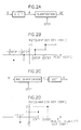
- Figs. 2A to 2D show a process of an information loss due to a quantization error.
- ) between the original DCT coefficient value F and the inversely quantized DCT coefficient F' may be 1 2 ⁇ step at its maximum. Namely, the quantization error that which cause the blocking effect in the digital image falls within 0 ⁇
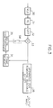
- Fig. 3 shows a motion picture decoder comprising an apparatus for removing blocking effect 36 of the present invention, which is connected to an end portion of the decoder in Fig. 1.
- Decoded image signals and a quantized step size information are inputted into the apparatus for removing blocking effect 36 such that blocking effects in the image signals are removed and the corrected image signals are outputted.
- Fig. 4 shows a first embodiment of the apparatus for removing blocking effect 36 .
- the apparatus for removing blocking effect 36 comprises a frame memory 40 ; a current block boundary pixel extractor 41 ; a adjacent block boundary pixel extractor 42 ; a mean value calculator 43 ; a mean value limiter 44 ; a current block extractor 45 ; aid an adder 46 .
- the mean value limiter 44 comprises a multiply 44-1 for multiplying quantized step size by 1 2 ; a selector 44-2 for selecting and outputting a minimum MIN; a multiply 44-3 for multiplying the quantized step size by - 1 2 and a selector 44-4 for selecting and outputting a maximum MAX .
- Fig. 5 shows 8 ⁇ 8 pixel current block, adjacent upper, lower, left, and right blocks and boundary pixels between each block.
- the boundary pixels a 0 -a 7 of the current block correspond to the boundary pixels A 0 -A 7 of the upper adjacent block A .
- the boundary pixels b 0 -b 7 of the current block correspond to the boundary pixels B 0 -B 7 of the left adjacent block B .
- the boundary pixels c 0- c 7 of the current block correspond to the boundary pixels C 0 -C 7 of the lower adjacent block C .
- the boundary pixels d 0 -d 7 of the current block correspond to the boundary pixels D 0 -D 7 of the right adjacent block D .
- the decoded image signals are inputted and stored in the frame memory 40 in frame units.
- boundary pixels values l of the current block which lies between the current block and the adjacent blocks are extracted from the frame memory 40 . Namely, 32 boundary pixel values a 0 -a 7 , b 0 -b 7 , c 0 -c 7 , d 0 -d 7 are outputted sequentially from the current block boundary pixel extractor 41 .
- boundary pixels values m of the adjacent blocks, which lies between the current block and the adjacent blocks are extracted from the frame memory 40 . Namely, 32 boundary pixel values A 0 -A 7 , B 0 -B 7 , C 0 -C 7 , D 0 -D 7 are outputted sequentially from the adjacent block boundary pixel extractor 42 .
- the mean value calculator 43 the pixel values l of the current block and the pixel values m of the adjacent blocks are sequentially inputted. Each difference value l- m between the inputted pixel values is calculated by the mean value calculator 43 . Further, a mean value for each difference value is calculated and ouputted from the mean value calculator 43 .
- the mean value is obtained by the following expression.
- the mean value limiter 44 the mean value and a quantization step size are inputted.
- the inputted mean value is limited between the minimum - 1 2 ⁇ step and maximum 1 2 ⁇ step by the mean value limiter 44 , and the limited mean value LIM is outputted.
- the minimum selector 44-2 the mean value is compared to maximum 1 2 ⁇ step to select a smaller value.
- the maximum selector 44-4 the smaller value obtained from the minimum selector 44-2 is compared to the minimum - 1 2 ⁇ step to select a bigger value.
- the limited mean value LIM from the maximum selector 44-4 is outputted to the adder 46 .
- the current block extractor 45 the current block is extracted from the frame memory 40. 64 pixel values of the extracted current block are sequentially outputted to the adder 46 .
- the limited mean value LIM from the mean value limiter 44 is added to each pixel value of the current block outputted from the current block extractor 45 .
- the added and corrected current block is inputted into a display processor (not shown).
- the corrected current block is fed back to the frame memory 40 .
- the stored current block is replaced with the corrected currect block from the adder 46 . This corrected current block is used for removal of blocking effect in the next block.
- TH prevents a damage in edges of original image during the removal process of blocking effect.
- the threshold level is determined and an absolute value from the difference value between boundary pixels smaller than the threshold value is selected. For example, when a 256 level image is coded/decoded, the threshold value is obtained as the following. A range of quantization error falls within -4 to 4 when the quantization step size 8 is utilized, and a range of the absolute difference between boundaries of blocks can be predicted to be 0 to 8. Further, a mean absolute difference between the block boundary is determined to be 4 if the quantization error is an uniform distribution.
- the threshold level greater than 4 is selected since the threshold value must be greater than the differences of the boundary pixel values. Namely, when the determined threshold level is 4 and the absolute value
- the obtained mean value is inputted into the mean value limiter 44 for limiting the mean value within the range of quantization error.
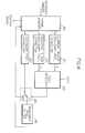
- Fig. 6 shows a second embodiment of the apparatus for removing blocking effect.
- the difference is attributed by either quantization error, which is occurred during transform coding or non-uniform (containing edge) current block. It is not desirable to indiscriminately utilize blocking effect removal process in existence of this difference, since the current block containing an edge would be distorted by the process.
- the second embodiment of the apparatus for removing blocking effect provides system for differentiating non-uniform block form uniform block to selectively remove blocking effect caused by the quantization error.
- the apparatus for blocking effect comprises a frame memory 60 , a current block boundary pixel extractor 61 , an adjacent block boundary pixel extractor 62 , an edge detector 63 , a boundary pixel extractor 64 , a selector 65 , and a boundary pixel filter 66 .
- the decoded image signals are stored in frame units.
- the stored pixel values in the frame memory 60 are corrected by boundary pixel values of the feedback current block.
- the corrected frame is outputted from the frame memory 60 to a display processor (not shown).
- a role and an operation of the current block boundary pixel extractor 61 and the adjacent block boundary pixel extractor 62 are same as the current block boundary pixel extractor 41 and the adjacent block boundary pixel extractor 42 of the first preferred embodiment.
- edge detector 63 boundary pixel values l of the current block boundary and boundary pixel values m adjacent blocks are inputted. According to the quantization step size, a first selection signal is outputted if the boundary of the current block is uniform (not an edge). whereas a second selection signal is outputted if the boundary of the current block is not uniform (an edge).
- an edge is detected by the edge detector 63 , if all the absolute difference values are less than equal to the threshold level, the edge detector 63 determines that the current block is uniform (edge free) and the removal of the blocking effect is needed. If the absolute difference value is greater than the threshold value, the current block is determined to be non-uniform (containing edge) and the removal of the blocking effect is not needed.
- the threshold level is 4.
- 32 boundary pixel values l i , a 0 -a 7 , b 0 -b 7 , c 0 -c 7 , d 0 -d 7 are inputted sequentially from the current block boundary pixel extractor 61.
- 32 boundary pixel values m i , A 0 -A 7 , B 0 -B 7 , C 0 -C 7 , D 0 -D 7 are inputted sequentially from the adjacent block boundary pixel extractor 62 .
- between each inputted pixel is obtained by the edge detector 63 .
- the first selection signal is outputted when each of 32 absolute difference values is
- the second selection signal is outputted when any of 32 absolute difference values is
- boundary pixel values a 0 -a 7 , b 0 -b 7 , c 0 -c 7 , d 0 -d 7 of the current block from the frame memory 60 and upper and lower pixel values of the boundary pixel are extracted.
- the pixel values from the boundary pixel extractor 64 are inputted in the boundary pixel filter 66 according to the first selection signal.
- the pixel values outputted from the boundary pixel extractor 64 are directly fed back to the frame memory 60 in presence of second selection signal. Further, if the pixels are determined to not to have an edge, a plurality of adjacent pixels are outputted to boundary pixel filter 66 , whereas the pixels are fed back to the frame memory 60 if the pixels are determined to have an edge.
- the boundary pixel filter 66 a plurality of boundary pixels outputted from the selector 65 are corrected.
- the corrected pixel values are inputted in the frame memory 60 .
- the boundary pixel values are multiplied by filter coefficients respectively, and the sum of the multiplied values is the corrected pixel values.
- the boundary pixel functions as a low pass filter by utilizing a 5-tap mean filter having filter coefficients [ 1 5 , 1 5 , 1 5 , 1 5 , 1 5 ].
- the corrected boundary pixel values by the boundary pixel filter 66 are [ 1 5 n 1 , 1 5 n 2 , 1 5 n 3 , 1 5 n 4 , 1 5 n 5 ].
- the block not having an edge is filtered, whereas the block detected to have an edge is not filtered. Accordingly. the removal of the blocking effect is processed selectively without distorting the original images.
Abstract
Description
- The present invention relates to methods and apparatuses for removing blocking effect caused by quantization error in a motion picture decoder.
- In general, the amount of data associated with visual information is so large that its storage would require enormous storage capacity. Although the capacities of utilizing several storage media are substantial, the access speeds are usually inversely proportional to the capacity. Storage and transmission of such data require large capacity and bandwidth. To eliminate the need for large storage capacity, there is an image data compression technique, which reduces the number of bits required to store or transmit image without any appreciable loss of data.
- The image data compression removes redundancies contained in image signals. The redundancies comprises a spectral redundancy among colors, a temporal redundancy between successive screens, a spatial redundancy between adjacent pixels within the screen, and a statistical redundancy. Here, a method of image coding for removing the spatial redundancy is transform coding, which divides original input images into small size blocks and processes them individually.
- In the transmitter, each blocks of original image is converted by the transform coding and transform coefficients are generated. The transform coefficients are quantized and transmitted to the receiver. In the receiver, the transform coefficients are inverse quantized and converted so that each blocks of original image is regenerated.
- Fig. 1 shows a block diagram of a conventional digital motion picture coder/decoder, which is widely used in image processing system such as a High Definition Television (HDTV).
- In Fig. 1, the motion picture coder comprises a differential image generator (DIG), a discrete cosine transform unit (DCT unit), a quantizer (Q), a variable length coding unit (VLC unit), an inverse quantizer (IQ), an inverse discrete cosine transform unit (IDCT unit), an adder (ADD), a frame memory, a motion estimator, and a motion compensator.
- In DIG, a current image and a predicted image are inputted, and a differential image is generated. The generated differential image is outputted to thc DCT unit to be divided into blocks. The DCT unit processes every block into DCT coefficients. The DCT coefficients are then quantized according to a quantization step size in the quantizer. The quantized coefficients are coded according to the Huffman Table in the VLC unit. The quantized coded coefficients are then transmitted to the channel.
- The predicted image inputted to the DIG is obtained as following. First, quantized DCT coefficients from the quantizer are quantized inversely in the inverse quantizer. The inverse quantized DCT coefficients are converted to image data in the IDCT. The converted image data are inputted to the adder. In the adder, original images are regenerated by using the transformed image data and previous image data from the motion compensator. The regenerated images from the adder are stored in the frame memory. From the frame memory, the previous images are outputted by delaying them in frame units. In the motion estimator, the previous image signals from the frame memory and the current image signals are compared for difference between the two frames, and a motion vector is generated. In the motion compensator, the predicted image having a pixel value similar to the current frame is outputted by shifting the previous image signal outputted from the frame memory as much as the motion vector.
- In the motion picture coder like the above, intra-mode frames are coded and transmitted. However, in the case of inter-mode frames, differential signals obtained through the motion estimation and the motion compensation should be coded and transmitted in order to decrease the transmission rate. To solve the above problem, a switch is disposed between the DIG and the motion compensator. Accordingly, the switch is opened when the intra-frames are inputted, and the switch is closed when the inter-frames are inputted.
- The motion picture decoder comprises a variable length decoding unit (VLD unit), an inverse quantizer, an inverse discrete cosine transform unit (IDCT unit), an adder, a frame memory, and a motion compensator.
- In the motion picture decoder, the input image signals are decoded by the VLD unit. The decoded signals are then quantized inversely by the inverse quantizer. The inverse quantized image data are converted inversely by the IDCT unit to be outputted to the adder. The image data from the adder are stored and delayed in the frame memory. The consequent stored delayed data from the frame memory are outputted to the motion compensator in order to be compensated with reference to the previous images. The compensated signals are then outputted to the adder.
- The intra-mode frames and inter-mode frames are regenerated according to the switch disposed between the adder and motion compensator. Namely, in case of the intra-mode frames, the output data from the IDCT unit are directly outputted to the adder. However, in case of the inter-mode frames, the output data from the IDCT are added to the previous image data from the motion compensator and the resulting data are transmitted to the adder to regenerate a current image signal.
- In the decoded digital images like the above, blocking effect occurs near to discontinuous boundary between blocks. The occurrence of this blocking effect is generated during the transform coding process of the divided blocks of digital images. Further, when the quantization step size is expanded during quantization, the quantization error increases and the blocking effect in the discontinuous boundary between blocks becomes even more apparent.
- In view of the foregoing, it is an object of the present invention to provide methods and apparatuses for removing blocking effect due to a quantization error in a motion picture decoder having loss to the original image data.
- In order to achieve the above object, the present invention provides a method for removing blocking effect in a motion picture decoder comprising the steps of extracting boundary pixel values of a current block; extracting boundary pixel values of each adjacent block; extracting difference values between boundary pixel values of the current block and boundary pixel values of each adjacent block; calculating the mean value for the difference values; limiting the mean value between -


- In addition, an apparatus for removing blocking effect in the motion picture decoder of the present invention comprises a frame memory for simultaneously receiving and storing decoded image signals in frame units and a corrected feedback current block with removed blocking effect; a current block boundary pixel extracting means for extracting boundary pixel values of the current block of frames stored in the frame memory; an adjacent block boundary pixel extracting means for extracting boundary pixel values of adjacent blocks of frames stored in the frame memory; a mean value calculating means for calculating difference values between boundary pixel values of the current block and of the adjacent blocks. and a mean value of the difference values; a mean value limiting means for limiting the mean value between -


- In another aspect. the present invention provides a method for removing blocking effect in a motion picture decoder comprising steps of extracting boundary pixel values within a current block and each adjacent block; calculating absolute values for difference values between boundary pixel values of the current block and boundary pixel values of each adjacent block; detecting whether a boundary of the current block is an edge or not, by comparing the difference values, the absolute values, and a threshold level to each other; and extracting corrected pixel values by filtering one pixel value of boundary pixels of the current block and a plurality of upper and lower pixels referencing the boundary pixel of the current block as a center if the boundary pixel values of the current block is uniform (not an edge), otherwise extracting directly boundary pixel values of the current block if the boundary pixel values of the current block is not uniform (an edge).
- In still another aspect, the present invention provides an apparatus for removing blocking effect comprising a frame memory for receiving and storing decoded image signals in frame units and a corrected feedback current block with removed blocking effect; a current block boundary pixel extracting means for extracting sequentially boundary pixel values of the current block stored in the frame memory; an adjacent block boundary extracting means for extracting sequentially boundary pixel values of adjacent blocks stored in the frame memory; an edge detecting means for outputting a first selection signal if the boundary pixel values of the current block are not an edge, whereas outputting a second selection signal if the boundary pixel values of the current block are an edge after receiving pixel values of the current block and boundary pixel values of an adjacent block; an input pixel extracting means for outputting in parallel a boundary pixel value of the current block and a plurality of upper and lower pixel values referencing the boundary pixel value of current block as a center in accordance with an output order of boundary pixel values of the current block from the frame memory; a selecting means for inputting pixel values from the input pixel extracting means to a boundary pixel filtering means according to the first selection signal, and inputting directly pixel values from the input pixel extracting means to the frame memory according to the second selection signal; and a boundary pixel filtering means for feeding back corrected boundary pixel values to the frame memory by filtering the output pixel values from the selecting means.
- The above and other objects, features, and advantages of the present invention will be apparent from the following detailed description of the preferred embodiments of the invention in conjunction with the accompanying drawings, in which:
- Fig. 1 is a block diagram illustrating a conventional motion picture coder and decoder;
- Figs. 2A to 2D are views illustrating loss of an information due to a quantization error;
- Fig. 3 is a block diagram illustrating a motion picture decoder comprising an apparatus for removing blocking effect in accordance with the present invention;
- Fig. 4 is a block diagram illustrating an apparatus for removing blocking effect in accordance with a first preferred embodiment of the present invention;
- Fig. 5 is a view illustrating transformed 8 × 8 pixels of current block and upper, lower, left, right adjacent blocks;
- Fig. 6 is a block diagram illustrating an apparatus for removing blocking effect in accordance with a second preferred embodiment of the present invention; and
- Fig. 7 is a view illustrating a plurality of pixel extracted from boundary pixels of a current block for describing an operation of an input pixel extractor in Fig. 6.
- Reference will now be made in detail to the present invention, examples of which are illustrated in the accompanying drawings. Wherever possible, the same reference numbers will be used throughout the drawings to refer to the same or like parts.
- Figs. 2A to 2D show a process of an information loss due to a quantization error. When a DCT coefficient is quantized according to a quantization step size, the quantized DCT coefficient is expressed by QF= [


- Fig. 3 shows a motion picture decoder comprising an apparatus for removing blocking
effect 36 of the present invention, which is connected to an end portion of the decoder in Fig. 1. Decoded image signals and a quantized step size information are inputted into the apparatus for removing blockingeffect 36 such that blocking effects in the image signals are removed and the corrected image signals are outputted. - Fig. 4 shows a first embodiment of the apparatus for removing blocking
effect 36. The apparatus for removing blockingeffect 36 comprises aframe memory 40; a current blockboundary pixel extractor 41; a adjacent blockboundary pixel extractor 42; amean value calculator 43; amean value limiter 44; acurrent block extractor 45; aid anadder 46. Themean value limiter 44 comprises a multiply 44-1 for multiplying quantized step size by

- Fig. 5 shows 8 × 8 pixel current block, adjacent upper, lower, left, and right blocks and boundary pixels between each block. Here, the current block for removal of blocking effect is illustrated. The boundary pixels a 0 -a 7 of the current block correspond to the boundary pixels A 0 -A 7 of the upper adjacent block A. The boundary pixels b 0 -b 7 of the current block correspond to the boundary pixels B 0 -B 7 of the left adjacent block B. The boundary pixels c 0- c 7 of the current block correspond to the boundary pixels C 0 -C 7 of the lower adjacent block C. The boundary pixels d 0 -d 7 of the current block correspond to the boundary pixels D 0 -D 7 of the right adjacent block D.
- In Fig. 4, the decoded image signals are inputted and stored in the
frame memory 40 in frame units. In the current blockboundary pixel extractor 41, boundary pixels values ℓ of the current block, which lies between the current block and the adjacent blocks are extracted from theframe memory 40. Namely, 32 boundary pixel values a 0 -a 7 , b 0 -b 7 , c 0 -c 7 , d 0 -d 7 are outputted sequentially from the current blockboundary pixel extractor 41. - In addition, by the adjacent block
boundary pixel extractor 42, boundary pixels values m of the adjacent blocks, which lies between the current block and the adjacent blocks are extracted from theframe memory 40. Namely, 32 boundary pixel values A 0 -A 7 , B 0 -B 7 , C 0 -C 7 , D 0 -D 7 are outputted sequentially from the adjacent blockboundary pixel extractor 42. - In the
mean value calculator 43, the pixel values ℓ of the current block and the pixel values m of the adjacent blocks are sequentially inputted. Each difference value ℓ-m between the inputted pixel values is calculated by themean value calculator 43. Further, a mean value for each difference value is calculated and ouputted from themean value calculator 43. The mean value is obtained by the following expression.
- The
above equation 1 is applied when there are 4 adjacent blocks. However. when there are 2 or 3 adjacent blocks, the mean value is obtained by dividing all the added boundary pixel values by 24 or 16 respectively. - In the
mean value limiter 44, the mean value and a quantization step size are inputted. The inputted mean value is limited between the minimum -

mean value limiter 44, and the limited mean value LIM is outputted. Namely, in the minimum selector 44-2, the mean value is compared tomaximum 

adder 46. - In the
current block extractor 45, the current block is extracted from theframe memory 40. 64 pixel values of the extracted current block are sequentially outputted to theadder 46. - In the
adder 46, the limited mean value LIM from themean value limiter 44 is added to each pixel value of the current block outputted from thecurrent block extractor 45. The added and corrected current block is inputted into a display processor (not shown). In addition, the corrected current block is fed back to theframe memory 40. In theframe memory 40, the stored current block is replaced with the corrected currect block from theadder 46. This corrected current block is used for removal of blocking effect in the next block. - Another method for calculating the mean value utilizes a threshold level TH. TH prevents a damage in edges of original image during the removal process of blocking effect. To obtain the mean value M, the threshold level is determined and an absolute value from the difference value between boundary pixels smaller than the threshold value is selected. For example, when a 256 level image is coded/decoded, the threshold value is obtained as the following. A range of quantization error falls within -4 to 4 when the quantization step size 8 is utilized, and a range of the absolute difference between boundaries of blocks can be predicted to be 0 to 8. Further, a mean absolute difference between the block boundary is determined to be 4 if the quantization error is an uniform distribution. Accordingly, the threshold level greater than 4 is selected since the threshold value must be greater than the differences of the boundary pixel values. Namely, when the determined threshold level is 4 and the absolute value | ℓi - m i | of differences between the boundary pixel values of less than or equal to 4 is selected to yield a mean value M, At this time, the mean value M is obtained by the following expression.

- The obtained mean value is inputted into the
mean value limiter 44 for limiting the mean value within the range of quantization error. - Fig. 6 shows a second embodiment of the apparatus for removing blocking effect. When there is a drastic difference between the boundary pixel values of the current block and the boundary pixel values of the adjacent blocks, the difference is attributed by either quantization error, which is occurred during transform coding or non-uniform (containing edge) current block. It is not desirable to indiscriminately utilize blocking effect removal process in existence of this difference, since the current block containing an edge would be distorted by the process. The second embodiment of the apparatus for removing blocking effect provides system for differentiating non-uniform block form uniform block to selectively remove blocking effect caused by the quantization error. The apparatus for blocking effect comprises a
frame memory 60, a current blockboundary pixel extractor 61, an adjacent blockboundary pixel extractor 62, anedge detector 63, aboundary pixel extractor 64, aselector 65, and aboundary pixel filter 66. - In the
frame memory 60, the decoded image signals are stored in frame units. The stored pixel values in theframe memory 60 are corrected by boundary pixel values of the feedback current block. When corresponding blocks are corrected, the corrected frame is outputted from theframe memory 60 to a display processor (not shown). - A role and an operation of the current block
boundary pixel extractor 61 and the adjacent blockboundary pixel extractor 62 are same as the current blockboundary pixel extractor 41 and the adjacent blockboundary pixel extractor 42 of the first preferred embodiment. - In the
edge detector 63, boundary pixel values ℓ of the current block boundary and boundary pixel values m adjacent blocks are inputted. According to the quantization step size, a first selection signal is outputted if the boundary of the current block is uniform (not an edge). whereas a second selection signal is outputted if the boundary of the current block is not uniform (an edge). After extracting absolute difference values between the boundary pixel values of the current block and the boundary pixel values of the adjacent blocks, an edge is detected by theedge detector 63, if all the absolute difference values are less than equal to the threshold level, theedge detector 63 determines that the current block is uniform (edge free) and the removal of the blocking effect is needed. If the absolute difference value is greater than the threshold value, the current block is determined to be non-uniform (containing edge) and the removal of the blocking effect is not needed. - For example, as in Fig. 3, consider that there are 4 adjacent blocks to the current block and the threshold level is 4. in the
edge detector boundary pixel extractor 61. In addition, in theedge detector boundary pixel extractor 62. The absolute difference values |ℓi - m i | between each inputted pixel is obtained by theedge detector 63. After comparing 32 absolute difference values to the threshold level respectively, the first selection signal is outputted when each of 32 absolute difference values is |ℓi - m i | ≤ 4, whereas the second selection signal is outputted when any of 32 absolute difference values is | li - mi | > 4. - In the
boundary pixel extractor 64, boundary pixel values a 0 -a 7 , b 0 -b 7 , c 0 -c 7 , d 0 -d 7 of the current block from theframe memory 60 and upper and lower pixel values of the boundary pixel are extracted. The extracted pixel values are sequentially outputted in parallel. For example, as in Fig. 7, consider a boundary pixel value A3 of the current block. Two upper pixels and two lower pixels are additionally extracted centering A3. Then, assuming A3=n3, total of 5 pixels n1, n2, n3, n4, n5 are outputted in parallel. - In the
selector 65, the pixel values from theboundary pixel extractor 64 are inputted in theboundary pixel filter 66 according to the first selection signal. The pixel values outputted from theboundary pixel extractor 64 are directly fed back to theframe memory 60 in presence of second selection signal. Further, if the pixels are determined to not to have an edge, a plurality of adjacent pixels are outputted toboundary pixel filter 66, whereas the pixels are fed back to theframe memory 60 if the pixels are determined to have an edge. - In the
boundary pixel filter 66, a plurality of boundary pixels outputted from theselector 65 are corrected. The corrected pixel values are inputted in theframe memory 60. Namely, the boundary pixel values are multiplied by filter coefficients respectively, and the sum of the multiplied values is the corrected pixel values. For example, the boundary pixel functions as a low pass filter by utilizing a 5-tap mean filter having filter coefficients [


boundary pixel extractor 64, the corrected boundary pixel values by theboundary pixel filter 66 are [


- As described above, the block not having an edge is filtered, whereas the block detected to have an edge is not filtered. Accordingly. the removal of the blocking effect is processed selectively without distorting the original images.
- While this invention has been described in connection with what is presently considered to be the most practical and preferred embodiments, it is to be understood that the invention is not limited to the disclosed embodiment, but, on the contrary, it is intended to cover various modifications and equivalent arrangements included within the scope of the appended claims.
Claims (10)
- A method for removing blocking effect comprising the steps of:a) extracting boundary pixel values of a current block and each adjacent block to said current block, which exist between boundaries of said current block and said each adjacent block;b) extracting difference values between boundary pixel values of said current block and boundary pixel values of said each adjacent block, and calculating the mean value for the difference values;c) limiting the mean value between -

 d) adding the limited mean value to said each pixel value of said current block, and outputting corrected images.
 - The method for removing blocking effect in a motion picture decoder of claim 1, wherein said step of calculating the mean value comprises the steps of:calculating difference values between boundary pixel values of said current block and of said adjacent blocks; andcalculating a mean value for the difference values.
- The method for removing blocking effect in a motion picture decoder of claim 1, wherein the step of calculating the mean value comprises the steps of:extracting difference values between the boundary pixel values of said current block and of said adjacent blocks;selecting and accumulating boundary pixel difference values when absolute values are less than a threshold level after comparing said absolute values to said difference values to said threshold level respectively; andcalculating a mean value for said accumulated difference values.
- An apparatus for removing blocking effect in a motion picture decoder comprising:a) a frame memory for receiving and storing decoded image signals in frame units and a corrected feedback current block;b) a current block boundary pixel extracting means for extracting sequentially boundary pixel values of said current block stored in the frame memory;c) an adjacent block boundary extracting means for extracting sequentially boundary pixel values of adjacent blocks to said current block stored in the frame memory;d) a mean value calculating means for calculating a mean value for difference values between boundary pixel values of said current block and of said adjacent blocks, and outputting a mean value;e) a mean value limiting means for limiting the mean value between -

 f) a current block extracting means for extracting a current block stored in the frame memory, and outputting pixel values of said current block; andg) an adding means for adding the mean value from said mean value limiting means to each pixel value of said current block from said current block extracting means for outputting the corrected current block, and feeding back said corrected current block to said frame memory.
 - The apparatus for removing blocking effect in a motion picture decoder of ciaim 4, wherein the mean value limiting means comprises:a multiplying means for multiplying the quantized step size by
 a selecting means for selecting and outputting a minimum;a multiplying means for multiplying the quantized step size -
 a selecting means for selecting and outputting a maximum.
 - A method for removing blocking effect in a motion picture decoder comprising the steps of:a) extracting boundary pixel values of a current block and each adjacent block to said current block, which exist between boundaries of said current block and said each adjacent block;b) calculating absolute values for difference values between boundary pixel values of said current block and boundary pixel values of said each adjacent block;c) detecting whether a boundary of said current block contains an edge or not, by comparing the difference values, the absolute values, and a threshold level; andd) extracting corrected pixel values by filtering one pixel value of boundary pixels of said current block and a plurality of upper and lower pixels referencing said boundary pixel value as a center if the boundary of said current block does not have an edge, whereas extracting directly boundary pixel values of said current block if the boundary of said current block has an edge.
- The method for removing blocking effect in a motion picture decoder of claim 6, wherein if said all absolute difference values are less than or equal to a threshold level, the block is determined not to contain an edge, but when any of said absolute difference values is more than the threshold level, the block is determined to contain an edge.
- An apparatus for removing blocking effect in a motion picture decoder comprising:a) a frame memory for receiving and storing decoded image signals in frame units and a corrected feedback current block;b) a current block boundary pixel extracting means for extracting sequentially boundary pixel values of a current block stored in the frame memory;c) an adjacent block boundary extracting means for extracting sequentially boundary pixel values of adjacent blocks to said current block stored in the frame memory;d) an edge detecting means for outputting a first selection signal if the current block does not contain an edge, whereas outputting a second selection signal if said current block contain an edge after receiving pixel values of said current block and boundary pixel values of an adjacent block;e) a boundary pixel extracting means for extracting and outputting in parallel a pixel value and a plurality of upper and lower pixels referencing said pixel value as a center according to an output order of boundary pixel values of said current block from said frame memory;t) a selecting means for inputting pixel values from said boundary pixel extracting means to a boundary pixel filtering means according to the first selection signal, and inputting directly pixel values from said boundary pixel extracting means to said frame memory according to the second selection signal; andg) a boundary pixel filtering means for filtering pixel values form said selecting means and feeding back corrected boundary pixel values to said frame memory.
- The apparatus for removing blocking effect in a motion picture decoder of claim 8, wherein said edge detecting means comprises:a subtracting means for calculating difference values between boundary pixel values of said current block and said adjacent blocks;an absolute value calculating means for calculating absolute values for the difference values; anda selection signal generating means for outputting a first selection signal if all absolute difference values are less than or equal to a threshold level, whereas outputting a second selection signal if any of all absolute difference values is more than the threshold level, by comparing the absolute difference values and a threshold level.
- The apparatus for removing blocking effect in a motion picture decoder of claim 8, wherein said boundary pixel filtering means is a low pass filter.
Priority Applications (1)
| Application Number | Priority Date | Filing Date | Title |
|---|---|---|---|
| EP04075207A EP1469680B1 (en) | 1996-05-14 | 1997-05-13 | Method and apparatus for removing blocking effects in a motion picture decoder |
Applications Claiming Priority (8)
| Application Number | Priority Date | Filing Date | Title |
|---|---|---|---|
| KR1019960016005A KR100230839B1 (en) | 1996-05-14 | 1996-05-14 | Block cancelation method and apparatus in moving picture decoder |
| KR9616005 | 1996-05-14 | ||
| KR1019960016011A KR100230842B1 (en) | 1996-05-14 | 1996-05-14 | Block cancelation method and apparatus in moving picture decoder |
| KR9616011 | 1996-05-14 | ||
| KR1019960016007A KR100230841B1 (en) | 1996-05-14 | 1996-05-14 | Block cancelation method and apparatus in moving picture decoder |
| KR1019960016006A KR100230840B1 (en) | 1996-05-14 | 1996-05-14 | The block cancelation method and apparatus in moving picture decoder |
| KR9616006 | 1996-05-14 | ||
| KR9616007 | 1996-05-14 |
Related Child Applications (1)
| Application Number | Title | Priority Date | Filing Date |
|---|---|---|---|
| EP04075207A Division EP1469680B1 (en) | 1996-05-14 | 1997-05-13 | Method and apparatus for removing blocking effects in a motion picture decoder |
Publications (3)
| Publication Number | Publication Date |
|---|---|
| EP0808068A2 true EP0808068A2 (en) | 1997-11-19 |
| EP0808068A3 EP0808068A3 (en) | 1998-05-06 |
| EP0808068B1 EP0808068B1 (en) | 2004-08-25 |
Family
ID=27483129
Family Applications (2)
| Application Number | Title | Priority Date | Filing Date |
|---|---|---|---|
| EP04075207A Expired - Lifetime EP1469680B1 (en) | 1996-05-14 | 1997-05-13 | Method and apparatus for removing blocking effects in a motion picture decoder |
| EP97303246A Expired - Lifetime EP0808068B1 (en) | 1996-05-14 | 1997-05-13 | Methods and apparatus for removing blocking effect in a motion picture decoder |
Family Applications Before (1)
| Application Number | Title | Priority Date | Filing Date |
|---|---|---|---|
| EP04075207A Expired - Lifetime EP1469680B1 (en) | 1996-05-14 | 1997-05-13 | Method and apparatus for removing blocking effects in a motion picture decoder |
Country Status (5)
| Country | Link |
|---|---|
| US (1) | US6144700A (en) |
| EP (2) | EP1469680B1 (en) |
| JP (1) | JPH1051775A (en) |
| CN (1) | CN1179575C (en) |
| DE (2) | DE69738787D1 (en) |
Cited By (15)
| Publication number | Priority date | Publication date | Assignee | Title |
|---|---|---|---|---|
| EP1039760A2 (en) * | 1999-03-26 | 2000-09-27 | Victor Company Of Japan, Limited | Apparatus and method of block noise detection and reduction |
| DE19734881C2 (en) * | 1997-07-30 | 2002-04-25 | Lg Electronics Inc | Methods for reducing blockage artifacts generated when encoding film recordings |
| GB2329090B (en) * | 1997-09-09 | 2002-08-07 | Lg Semicon Co Ltd | Method of removing blocking artifacts in a coding system of a moving picture |
| WO2002096118A2 (en) * | 2001-05-18 | 2002-11-28 | Bytemobile, Inc. | Decoding compressed image data |
| US6496605B1 (en) * | 1996-08-02 | 2002-12-17 | United Module Corporation | Block deformation removing filter, image processing apparatus using the same, method of filtering image signal, and storage medium for storing software therefor |
| GB2399962A (en) * | 2003-03-27 | 2004-09-29 | Advanced Risc Mach Ltd | Data filtering |
| EP1549075A2 (en) * | 2003-11-28 | 2005-06-29 | Noritsu Koki Co., Ltd. | Method of reducing block and mosquito noise (effect) in images |
| US7003174B2 (en) | 2001-07-02 | 2006-02-21 | Corel Corporation | Removal of block encoding artifacts |
| WO2006018789A1 (en) * | 2004-08-16 | 2006-02-23 | Koninklijke Philips Electronics N.V. | Video processor comprising a sharpness enhancer |
| GB2429593A (en) * | 2005-08-26 | 2007-02-28 | Electrosonic Ltd | Data compressing using a wavelet compression scheme |
| US7454082B2 (en) | 1997-07-30 | 2008-11-18 | Lg Electronics Inc. | Method of reducing a blocking artifact when coding moving picture |
| CN100459714C (en) * | 2002-12-04 | 2009-02-04 | 皇家飞利浦电子股份有限公司 | Method of measuring blocking artefacts |
| ES2328439A1 (en) * | 1997-07-16 | 2009-11-12 | Samsung Electronics Co., Ltd | Signal adaptive filtering method, signal adaptive filter and computer readable medium for storing program therefor |
| EP1848220A3 (en) * | 2006-04-18 | 2011-09-28 | Pioneer Corporation | Block noise removal device |
| US9992252B2 (en) | 2015-09-29 | 2018-06-05 | Rgb Systems, Inc. | Method and apparatus for adaptively compressing streaming video |
Families Citing this family (31)
| Publication number | Priority date | Publication date | Assignee | Title |
|---|---|---|---|---|
| FI106071B (en) * | 1997-03-13 | 2000-11-15 | Nokia Mobile Phones Ltd | Adaptive filter |
| KR100282147B1 (en) | 1998-11-13 | 2001-02-15 | 구자홍 | Compressed Image Restoration Method |
| US6771827B1 (en) * | 1998-12-23 | 2004-08-03 | Xerox Corporation | System and method for directed acuity segmentation resolution compression and decompression |
| JP3530844B2 (en) * | 1999-12-17 | 2004-05-24 | 株式会社デジタルアクト | Image processing method and apparatus, and recording medium |
| US7450641B2 (en) * | 2001-09-14 | 2008-11-11 | Sharp Laboratories Of America, Inc. | Adaptive filtering based upon boundary strength |
| US7929610B2 (en) * | 2001-03-26 | 2011-04-19 | Sharp Kabushiki Kaisha | Methods and systems for reducing blocking artifacts with reduced complexity for spatially-scalable video coding |
| US6931063B2 (en) | 2001-03-26 | 2005-08-16 | Sharp Laboratories Of America, Inc. | Method and apparatus for controlling loop filtering or post filtering in block based motion compensationed video coding |
| CN1332560C (en) * | 2002-07-22 | 2007-08-15 | 上海芯华微电子有限公司 | Method based on difference between block bundaries and quantizing factor for removing block effect without additional frame memory |
| EP1631057A4 (en) * | 2003-05-27 | 2007-01-17 | Nikon Corp | Image processing device and image processing program |
| JP3698158B2 (en) * | 2003-06-27 | 2005-09-21 | 三菱電機株式会社 | Post filter, post filter processing method, and video signal decoding apparatus |
| US7277592B1 (en) | 2003-10-21 | 2007-10-02 | Redrock Semiconductory Ltd. | Spacial deblocking method using limited edge differences only to linearly correct blocking artifact |
| CN100361534C (en) * | 2004-06-14 | 2008-01-09 | 厦门华侨电子股份有限公司 | Method and device for removing block effect in video coding-decoding system |
| US7551322B2 (en) * | 2004-06-29 | 2009-06-23 | Intel Corporation | Image edge filtering |
| KR100614647B1 (en) * | 2004-07-02 | 2006-08-22 | 삼성전자주식회사 | Register array structure for effective edge filtering operation of deblocking filter |
| US8854389B2 (en) * | 2004-09-22 | 2014-10-07 | Intel Corporation | Apparatus and method for hardware-based video/image post-processing |
| US7515766B2 (en) * | 2004-09-22 | 2009-04-07 | Intel Corporation | Apparatus and method for edge handling in image processing |
| JP4457346B2 (en) * | 2004-11-12 | 2010-04-28 | ノーリツ鋼機株式会社 | Image noise removal method |
| KR100679035B1 (en) | 2005-01-04 | 2007-02-06 | 삼성전자주식회사 | Deblocking filtering method considering intra BL mode, and video encoder/decoder based on multi-layer using the method |
| CN100490537C (en) * | 2005-06-15 | 2009-05-20 | 华为技术有限公司 | Method for reducing image blocking effect |
| EP1903958A1 (en) | 2005-07-15 | 2008-04-02 | Atropos Limited | A wound retractor |
| KR100679047B1 (en) * | 2005-09-29 | 2007-02-05 | 삼성전자주식회사 | Method and apparatus for bit resolution extension |
| US8233535B2 (en) | 2005-11-18 | 2012-07-31 | Apple Inc. | Region-based processing of predicted pixels |
| EP2024929A2 (en) * | 2006-04-21 | 2009-02-18 | Koninklijke Philips Electronics N.V. | Picture enhancing increasing precision smooth profiles |
| TWI330041B (en) * | 2006-11-28 | 2010-09-01 | Realtek Semiconductor Corp | Image processing method and device for performing block effect reduction |
| US7876808B2 (en) * | 2006-11-30 | 2011-01-25 | Broadcom Corp. | Method and apparatus for adaptive noise and/or signal filtering in an HSDPA channel quality indicator (CQI) selection |
| EP2312853A1 (en) * | 2008-07-03 | 2011-04-20 | Sharp Kabushiki Kaisha | Filter device |
| WO2011033495A1 (en) | 2009-09-17 | 2011-03-24 | Atropos Limited | An instrument access device |
| US20120182388A1 (en) * | 2011-01-18 | 2012-07-19 | Samsung Electronics Co., Ltd. | Apparatus and method for processing depth image |
| EP2863637B1 (en) * | 2011-03-09 | 2018-12-12 | Nec Corporation | Video decoding device, video decoding method and video decoding program |
| KR20140119220A (en) * | 2013-03-27 | 2014-10-10 | 한국전자통신연구원 | Apparatus and method for providing recompression of video |
| US10645386B1 (en) * | 2019-01-03 | 2020-05-05 | Sony Corporation | Embedded codec circuitry for multiple reconstruction points based quantization |
Citations (6)
| Publication number | Priority date | Publication date | Assignee | Title |
|---|---|---|---|---|
| US5144688A (en) * | 1990-03-23 | 1992-09-01 | Board Of Regents, The University Of Texas System | Method and apparatus for visual pattern image coding |
| EP0502622A1 (en) * | 1991-02-27 | 1992-09-09 | Nortel Networks Corporation | Image processing method |
| EP0585573A2 (en) * | 1992-08-31 | 1994-03-09 | International Business Machines Corporation | System and method for suppressing blocking artifacts in decoded transform coded images |
| US5367385A (en) * | 1992-05-07 | 1994-11-22 | Picturetel Corporation | Method and apparatus for processing block coded image data to reduce boundary artifacts between adjacent image blocks |
| EP0723375A2 (en) * | 1995-01-20 | 1996-07-24 | Samsung Electronics Co., Ltd. | Post-processing device and method for eliminating blocking artifacts from decompressed images |
| EP0771116A2 (en) * | 1995-10-27 | 1997-05-02 | Kabushiki Kaisha Toshiba | Image processing apparatus |
Family Cites Families (6)
| Publication number | Priority date | Publication date | Assignee | Title |
|---|---|---|---|---|
| US5337088A (en) * | 1991-04-18 | 1994-08-09 | Matsushita Electric Industrial Co. Ltd. | Method of correcting an image signal decoded in block units |
| US5245677A (en) * | 1991-08-08 | 1993-09-14 | Hughes Aircraft Company | Directional running average segmentation |
| JPH06327002A (en) * | 1993-05-11 | 1994-11-25 | Olympus Optical Co Ltd | Moving image encoding device |
| KR970009302B1 (en) * | 1993-08-17 | 1997-06-10 | Lg Electronics Inc | Block effect reducing apparatus for hdtv |
| KR0174452B1 (en) * | 1995-02-28 | 1999-03-20 | 배순훈 | Digital image decoder |
| US5852475A (en) * | 1995-06-06 | 1998-12-22 | Compression Labs, Inc. | Transform artifact reduction process |
-
1997
- 1997-05-13 DE DE69738787T patent/DE69738787D1/en not_active Expired - Lifetime
- 1997-05-13 DE DE69730375T patent/DE69730375T2/en not_active Expired - Lifetime
- 1997-05-13 EP EP04075207A patent/EP1469680B1/en not_active Expired - Lifetime
- 1997-05-13 EP EP97303246A patent/EP0808068B1/en not_active Expired - Lifetime
- 1997-05-14 US US08/856,474 patent/US6144700A/en not_active Expired - Lifetime
- 1997-05-14 JP JP9124159A patent/JPH1051775A/en active Pending
- 1997-05-14 CN CNB971042667A patent/CN1179575C/en not_active Expired - Lifetime
Patent Citations (6)
| Publication number | Priority date | Publication date | Assignee | Title |
|---|---|---|---|---|
| US5144688A (en) * | 1990-03-23 | 1992-09-01 | Board Of Regents, The University Of Texas System | Method and apparatus for visual pattern image coding |
| EP0502622A1 (en) * | 1991-02-27 | 1992-09-09 | Nortel Networks Corporation | Image processing method |
| US5367385A (en) * | 1992-05-07 | 1994-11-22 | Picturetel Corporation | Method and apparatus for processing block coded image data to reduce boundary artifacts between adjacent image blocks |
| EP0585573A2 (en) * | 1992-08-31 | 1994-03-09 | International Business Machines Corporation | System and method for suppressing blocking artifacts in decoded transform coded images |
| EP0723375A2 (en) * | 1995-01-20 | 1996-07-24 | Samsung Electronics Co., Ltd. | Post-processing device and method for eliminating blocking artifacts from decompressed images |
| EP0771116A2 (en) * | 1995-10-27 | 1997-05-02 | Kabushiki Kaisha Toshiba | Image processing apparatus |
Cited By (56)
| Publication number | Priority date | Publication date | Assignee | Title |
|---|---|---|---|---|
| US6496605B1 (en) * | 1996-08-02 | 2002-12-17 | United Module Corporation | Block deformation removing filter, image processing apparatus using the same, method of filtering image signal, and storage medium for storing software therefor |
| US8942296B2 (en) | 1997-07-16 | 2015-01-27 | Samsung Electronics Co., Ltd. | Signal adaptive filtering method, signal adaptive filter and computer readable medium for storing program therefor |
| US9077959B1 (en) | 1997-07-16 | 2015-07-07 | Samsung Electronics Co., Ltd. | Signal adaptive filtering method, signal adaptive filter and computer readable medium for storing program therefor |
| US9060181B1 (en) | 1997-07-16 | 2015-06-16 | Samsung Electronics Co., Ltd. | Signal adaptive filtering method, signal adaptive filter and computer readable medium for storing program therefor |
| US9264705B2 (en) | 1997-07-16 | 2016-02-16 | Samsung Electronics Co., Ltd. | Signal adaptive filtering method, signal adaptive filter and computer readable medium for storing program therefor |
| US9060163B1 (en) | 1997-07-16 | 2015-06-16 | Samsung Electronics Co., Ltd. | Signal adaptive filtering method, signal adaptive filter and computer readable medium for storing program therefor |
| ES2328439A1 (en) * | 1997-07-16 | 2009-11-12 | Samsung Electronics Co., Ltd | Signal adaptive filtering method, signal adaptive filter and computer readable medium for storing program therefor |
| US8873643B2 (en) | 1997-07-16 | 2014-10-28 | Samsung Electronics Co., Ltd. | Signal adaptive filtering method, signal adaptive filter and computer readable medium for storing program therefor |
| US8638864B2 (en) | 1997-07-16 | 2014-01-28 | Samsung Electronics Co., Ltd. | Signal adaptive filtering method, signal adaptive filter and computer readable medium for storing program therefor |
| US8494048B2 (en) | 1997-07-16 | 2013-07-23 | Samsung Electronics Co., Ltd. | Signal adaptive filtering method, signal adaptive filter and computer readable medium for storing program therefor |
| US8295366B2 (en) | 1997-07-16 | 2012-10-23 | Samsung Electronics Co., Ltd. | Signal adaptive filtering method, signal adaptive filter and computer readable medium for storing program method |
| ES2328439B2 (en) * | 1997-07-16 | 2010-09-29 | Samsung Electronics Co., Ltd | IMAGE DATA FILTER PROCEDURE. |
| US7801216B2 (en) | 1997-07-16 | 2010-09-21 | Samsung Electronics Co., Ltd. | Signal adaptive filtering method, signal adaptive filter and computer readable medium for storing program therefor |
| US7616832B2 (en) | 1997-07-30 | 2009-11-10 | Video Enhancement Solutions LLC | Method of reducing a blocking artifact when coding moving picture |
| US8983225B2 (en) | 1997-07-30 | 2015-03-17 | Lg Electronics Inc. | Method of reducing a blocking artifact when coding moving picture |
| US9456221B2 (en) | 1997-07-30 | 2016-09-27 | Lg Electronics Inc. | Method of reducing a blocking artifact when coding moving picture |
| DE19734881C2 (en) * | 1997-07-30 | 2002-04-25 | Lg Electronics Inc | Methods for reducing blockage artifacts generated when encoding film recordings |
| US7454082B2 (en) | 1997-07-30 | 2008-11-18 | Lg Electronics Inc. | Method of reducing a blocking artifact when coding moving picture |
| US7463786B2 (en) * | 1997-07-30 | 2008-12-09 | Lg Electronics Inc. | Method of reducing a blocking artifact when coding moving picture |
| US7620262B2 (en) | 1997-07-30 | 2009-11-17 | Video Enhancement Solutions LLC | Method of reducing a blocking artifact when coding moving picture |
| US7492959B2 (en) | 1997-07-30 | 2009-02-17 | Lg Electronics Inc. | Method of reducing a blocking artifact when coding moving picture |
| US7492961B2 (en) * | 1997-07-30 | 2009-02-17 | Lg Electronics Inc. | Method of reducing a blocking artifact when coding moving picture |
| US7492960B2 (en) | 1997-07-30 | 2009-02-17 | Lg Electronics Inc. | Method of reducing a blocking artifact when coding moving picture |
| US7496239B2 (en) | 1997-07-30 | 2009-02-24 | Lg Electronics Inc. | Method of reducing a blocking artifact when coding moving picture |
| US7499598B2 (en) | 1997-07-30 | 2009-03-03 | Lg Electronics Inc. | Method of reducing a blocking artifact when coding moving picture |
| US7599571B2 (en) | 1997-07-30 | 2009-10-06 | Lg Electronics Inc. | Method of reducing a blocking artifact when coding moving picture |
| US7616833B2 (en) * | 1997-07-30 | 2009-11-10 | Video Enhancement Solutions LLC | Method of reducing a blocking artifact when coding moving picture |
| US7616831B2 (en) | 1997-07-30 | 2009-11-10 | Video Enhancement Solutions | Method of reducing a blocking artifact when coding moving picture |
| USRE42851E1 (en) | 1997-09-09 | 2011-10-18 | Video Enhancement Solutions LLC | Method of removing blocking artifacts in a coding system of a moving picture |
| GB2329090B (en) * | 1997-09-09 | 2002-08-07 | Lg Semicon Co Ltd | Method of removing blocking artifacts in a coding system of a moving picture |
| USRE42516E1 (en) | 1997-09-09 | 2011-07-05 | Video Enhancement Solutions, LLC | Method of removing blocking artifacts in a coding system of a moving picture |
| USRE42660E1 (en) | 1997-09-09 | 2011-08-30 | Video Enhancement Solutions LLC | Method of removing blocking artifacts in a coding system of a moving picture |
| USRE42693E1 (en) | 1997-09-09 | 2011-09-13 | Video Enhancement Solutions LLC | Method of removing blocking artifacts in a coding system of a moving picture |
| USRE42713E1 (en) | 1997-09-09 | 2011-09-20 | Video Enhancement Solutions LLC | Method of removing blocking artifacts in a coding system of a moving picture |
| US6975777B1 (en) | 1999-03-26 | 2005-12-13 | Victor Company Of Japan, Ltd. | Apparatus and method of block noise detection and reduction |
| EP1039760A2 (en) * | 1999-03-26 | 2000-09-27 | Victor Company Of Japan, Limited | Apparatus and method of block noise detection and reduction |
| EP1039760A3 (en) * | 1999-03-26 | 2003-10-29 | Victor Company Of Japan, Limited | Apparatus and method of block noise detection and reduction |
| WO2002096118A2 (en) * | 2001-05-18 | 2002-11-28 | Bytemobile, Inc. | Decoding compressed image data |
| WO2002096118A3 (en) * | 2001-05-18 | 2003-10-16 | Bytemobile Inc | Decoding compressed image data |
| US7003174B2 (en) | 2001-07-02 | 2006-02-21 | Corel Corporation | Removal of block encoding artifacts |
| CN100459714C (en) * | 2002-12-04 | 2009-02-04 | 皇家飞利浦电子股份有限公司 | Method of measuring blocking artefacts |
| GB2399962A (en) * | 2003-03-27 | 2004-09-29 | Advanced Risc Mach Ltd | Data filtering |
| GB2399962B (en) * | 2003-03-27 | 2005-12-21 | Advanced Risc Mach Ltd | Data filtering |
| US7315875B2 (en) | 2003-03-27 | 2008-01-01 | Arm Limited | Data filtering |
| US7415163B2 (en) | 2003-11-28 | 2008-08-19 | Noritsu Koki Co., Ltd. | Method of reducing noise in images |
| EP1549075A2 (en) * | 2003-11-28 | 2005-06-29 | Noritsu Koki Co., Ltd. | Method of reducing block and mosquito noise (effect) in images |
| EP1549075A3 (en) * | 2003-11-28 | 2006-12-27 | Noritsu Koki Co., Ltd. | Method of reducing block and mosquito noise (effect) in images |
| WO2006018789A1 (en) * | 2004-08-16 | 2006-02-23 | Koninklijke Philips Electronics N.V. | Video processor comprising a sharpness enhancer |
| US9924199B2 (en) | 2005-08-26 | 2018-03-20 | Rgb Systems, Inc. | Method and apparatus for compressing image data using compression profiles |
| US9204170B2 (en) | 2005-08-26 | 2015-12-01 | Rgb Systems, Inc. | Method for image data processing utilizing multiple transform engines |
| GB2429593A (en) * | 2005-08-26 | 2007-02-28 | Electrosonic Ltd | Data compressing using a wavelet compression scheme |
| US9930364B2 (en) | 2005-08-26 | 2018-03-27 | Rgb Systems, Inc. | Method and apparatus for encoding image data using wavelet signatures |
| US10051288B2 (en) | 2005-08-26 | 2018-08-14 | Rgb Systems, Inc. | Method and apparatus for compressing image data using a tree structure |
| US10244263B2 (en) | 2005-08-26 | 2019-03-26 | Rgb Systems, Inc. | Method and apparatus for packaging image data for transmission over a network |
| EP1848220A3 (en) * | 2006-04-18 | 2011-09-28 | Pioneer Corporation | Block noise removal device |
| US9992252B2 (en) | 2015-09-29 | 2018-06-05 | Rgb Systems, Inc. | Method and apparatus for adaptively compressing streaming video |
Also Published As
| Publication number | Publication date |
|---|---|
| EP1469680A3 (en) | 2005-10-05 |
| CN1174478A (en) | 1998-02-25 |
| CN1179575C (en) | 2004-12-08 |
| US6144700A (en) | 2000-11-07 |
| JPH1051775A (en) | 1998-02-20 |
| EP1469680B1 (en) | 2008-06-18 |
| EP0808068B1 (en) | 2004-08-25 |
| EP1469680A2 (en) | 2004-10-20 |
| DE69730375D1 (en) | 2004-09-30 |
| DE69730375T2 (en) | 2005-08-11 |
| EP0808068A3 (en) | 1998-05-06 |
| DE69738787D1 (en) | 2008-07-31 |
Similar Documents
| Publication | Publication Date | Title |
|---|---|---|
| EP1469680B1 (en) | Method and apparatus for removing blocking effects in a motion picture decoder | |
| US5610729A (en) | Noise reduction apparatus for reducing noise in decoding of moving picture sequence | |
| US6037986A (en) | Video preprocessing method and apparatus with selective filtering based on motion detection | |
| KR940006737B1 (en) | Picture image coding and decording apparatus | |
| US5475434A (en) | Blocking effect attenuation apparatus for high definition television receiver | |
| KR100265722B1 (en) | Image processing method and apparatus based on block | |
| EP1168824A2 (en) | Image processing method for reducing noise and blocking artifact in a digital image | |
| US20060088098A1 (en) | Method and arrangement for reducing the volume or rate of an encoded digital video bitstream | |
| EP1763249A2 (en) | Method and apparatus for encording and/decoding moving pictures | |
| EP1039760B1 (en) | Apparatus and method of block noise detection | |
| US20020097335A1 (en) | Video data processing device and video data processing method | |
| US6865229B1 (en) | Method and apparatus for reducing the “blocky picture” effect in MPEG decoded images | |
| WO2005112434A2 (en) | Noise filter for video processing | |
| US4504864A (en) | Nonlinear filtering of gray scale images | |
| EP1848220A2 (en) | Block noise removal device | |
| EP0714210A2 (en) | Method of reducing mosquito noise generated during decoding process of image data and device for decoding image data using the same | |
| EP1848219B1 (en) | Block noise removal device | |
| US4875095A (en) | Noise-shaping predictive coding system | |
| KR19980017213A (en) | Image Decoding System with Compensation Function for Degraded Image | |
| US5907636A (en) | Image signal decoder | |
| JP3327593B2 (en) | Television system for transmitting digital television images | |
| JP3627291B2 (en) | Block distortion removing apparatus and method | |
| JPH07143483A (en) | Adaptive post-processing filter | |
| US8027383B2 (en) | Mosquito noise reduction filter in digital decoders | |
| KR100237636B1 (en) | Apparatus for improving blocking effect |
Legal Events
| Date | Code | Title | Description |
|---|---|---|---|
| PUAI | Public reference made under article 153(3) epc to a published international application that has entered the european phase |
Free format text: ORIGINAL CODE: 0009012 |
|
| AK | Designated contracting states |
Kind code of ref document: A2 Designated state(s): DE FR GB NL |
|
| PUAL | Search report despatched |
Free format text: ORIGINAL CODE: 0009013 |
|
| AK | Designated contracting states |
Kind code of ref document: A3 Designated state(s): DE FR GB NL |
|
| 17P | Request for examination filed |
Effective date: 19981028 |
|
| 17Q | First examination report despatched |
Effective date: 20020925 |
|
| RAP1 | Party data changed (applicant data changed or rights of an application transferred) |
Owner name: DAEWOO ELECTRONICS CORPORATION |
|
| GRAP | Despatch of communication of intention to grant a patent |
Free format text: ORIGINAL CODE: EPIDOSNIGR1 |
|
| GRAS | Grant fee paid |
Free format text: ORIGINAL CODE: EPIDOSNIGR3 |
|
| GRAA | (expected) grant |
Free format text: ORIGINAL CODE: 0009210 |
|
| AK | Designated contracting states |
Kind code of ref document: B1 Designated state(s): DE FR GB NL |
|
| REG | Reference to a national code |
Ref country code: GB Ref legal event code: FG4D |
|
| REF | Corresponds to: |
Ref document number: 69730375 Country of ref document: DE Date of ref document: 20040930 Kind code of ref document: P |
|
| PLBE | No opposition filed within time limit |
Free format text: ORIGINAL CODE: 0009261 |
|
| STAA | Information on the status of an ep patent application or granted ep patent |
Free format text: STATUS: NO OPPOSITION FILED WITHIN TIME LIMIT |
|
| ET | Fr: translation filed | ||
| 26N | No opposition filed |
Effective date: 20050526 |
|
| REG | Reference to a national code |
Ref country code: DE Ref legal event code: R082 Ref document number: 69730375 Country of ref document: DE Representative=s name: KLUNKER, SCHMITT-NILSON, HIRSCH, DE |
|
| REG | Reference to a national code |
Ref country code: GB Ref legal event code: 732E Free format text: REGISTERED BETWEEN 20130404 AND 20130410 |
|
| REG | Reference to a national code |
Ref country code: DE Ref legal event code: R082 Ref document number: 69730375 Country of ref document: DE Representative=s name: KLUNKER, SCHMITT-NILSON, HIRSCH, DE Effective date: 20130313 Ref country code: DE Ref legal event code: R081 Ref document number: 69730375 Country of ref document: DE Owner name: MAPLE VISION TECHNOLOGIES INC., CA Free format text: FORMER OWNER: DAEWOO ELECTRONICS CORP., SEOUL/SOUL, KR Effective date: 20130313 |
|
| REG | Reference to a national code |
Ref country code: FR Ref legal event code: TP Owner name: MAPLE VISION TECHNOLOGIES INC., CA Effective date: 20131226 |
|
| PGFP | Annual fee paid to national office [announced via postgrant information from national office to epo] |
Ref country code: DE Payment date: 20150506 Year of fee payment: 19 |
|
| REG | Reference to a national code |
Ref country code: FR Ref legal event code: PLFP Year of fee payment: 20 |
|
| PGFP | Annual fee paid to national office [announced via postgrant information from national office to epo] |
Ref country code: NL Payment date: 20160510 Year of fee payment: 20 |
|
| PGFP | Annual fee paid to national office [announced via postgrant information from national office to epo] |
Ref country code: GB Payment date: 20160511 Year of fee payment: 20 |
|
| PGFP | Annual fee paid to national office [announced via postgrant information from national office to epo] |
Ref country code: FR Payment date: 20160412 Year of fee payment: 20 |
|
| REG | Reference to a national code |
Ref country code: DE Ref legal event code: R119 Ref document number: 69730375 Country of ref document: DE |
|
| PG25 | Lapsed in a contracting state [announced via postgrant information from national office to epo] |
Ref country code: DE Free format text: LAPSE BECAUSE OF NON-PAYMENT OF DUE FEES Effective date: 20161201 |
|
| REG | Reference to a national code |
Ref country code: NL Ref legal event code: MK Effective date: 20170512 |
|
| REG | Reference to a national code |
Ref country code: GB Ref legal event code: PE20 Expiry date: 20170512 |
|
| PG25 | Lapsed in a contracting state [announced via postgrant information from national office to epo] |
Ref country code: GB Free format text: LAPSE BECAUSE OF EXPIRATION OF PROTECTION Effective date: 20170512 |