EP0809973A2 - Cervical spine stabilization method and system - Google Patents
Cervical spine stabilization method and system Download PDFInfo
- Publication number
- EP0809973A2 EP0809973A2 EP97106888A EP97106888A EP0809973A2 EP 0809973 A2 EP0809973 A2 EP 0809973A2 EP 97106888 A EP97106888 A EP 97106888A EP 97106888 A EP97106888 A EP 97106888A EP 0809973 A2 EP0809973 A2 EP 0809973A2
- Authority
- EP
- European Patent Office
- Prior art keywords
- plate
- vertebra
- longitudinal members
- engaging
- end portion
- Prior art date
- Legal status (The legal status is an assumption and is not a legal conclusion. Google has not performed a legal analysis and makes no representation as to the accuracy of the status listed.)
- Granted
Links
Images


Classifications
-
- A—HUMAN NECESSITIES
- A61—MEDICAL OR VETERINARY SCIENCE; HYGIENE
- A61F—FILTERS IMPLANTABLE INTO BLOOD VESSELS; PROSTHESES; DEVICES PROVIDING PATENCY TO, OR PREVENTING COLLAPSING OF, TUBULAR STRUCTURES OF THE BODY, e.g. STENTS; ORTHOPAEDIC, NURSING OR CONTRACEPTIVE DEVICES; FOMENTATION; TREATMENT OR PROTECTION OF EYES OR EARS; BANDAGES, DRESSINGS OR ABSORBENT PADS; FIRST-AID KITS
- A61F5/00—Orthopaedic methods or devices for non-surgical treatment of bones or joints; Nursing devices; Anti-rape devices
- A61F5/01—Orthopaedic devices, e.g. splints, casts or braces
-
- A—HUMAN NECESSITIES
- A61—MEDICAL OR VETERINARY SCIENCE; HYGIENE
- A61B—DIAGNOSIS; SURGERY; IDENTIFICATION
- A61B17/00—Surgical instruments, devices or methods, e.g. tourniquets
- A61B17/56—Surgical instruments or methods for treatment of bones or joints; Devices specially adapted therefor
- A61B17/58—Surgical instruments or methods for treatment of bones or joints; Devices specially adapted therefor for osteosynthesis, e.g. bone plates, screws, setting implements or the like
- A61B17/68—Internal fixation devices, including fasteners and spinal fixators, even if a part thereof projects from the skin
- A61B17/70—Spinal positioners or stabilisers ; Bone stabilisers comprising fluid filler in an implant
- A61B17/7001—Screws or hooks combined with longitudinal elements which do not contact vertebrae
- A61B17/7044—Screws or hooks combined with longitudinal elements which do not contact vertebrae also having plates, staples or washers bearing on the vertebrae
-
- A—HUMAN NECESSITIES
- A61—MEDICAL OR VETERINARY SCIENCE; HYGIENE
- A61F—FILTERS IMPLANTABLE INTO BLOOD VESSELS; PROSTHESES; DEVICES PROVIDING PATENCY TO, OR PREVENTING COLLAPSING OF, TUBULAR STRUCTURES OF THE BODY, e.g. STENTS; ORTHOPAEDIC, NURSING OR CONTRACEPTIVE DEVICES; FOMENTATION; TREATMENT OR PROTECTION OF EYES OR EARS; BANDAGES, DRESSINGS OR ABSORBENT PADS; FIRST-AID KITS
- A61F5/00—Orthopaedic methods or devices for non-surgical treatment of bones or joints; Nursing devices; Anti-rape devices
- A61F5/01—Orthopaedic devices, e.g. splints, casts or braces
- A61F5/04—Devices for stretching or reducing fractured limbs; Devices for distractions; Splints
-
- A—HUMAN NECESSITIES
- A61—MEDICAL OR VETERINARY SCIENCE; HYGIENE
- A61B—DIAGNOSIS; SURGERY; IDENTIFICATION
- A61B17/00—Surgical instruments, devices or methods, e.g. tourniquets
- A61B17/56—Surgical instruments or methods for treatment of bones or joints; Devices specially adapted therefor
- A61B17/58—Surgical instruments or methods for treatment of bones or joints; Devices specially adapted therefor for osteosynthesis, e.g. bone plates, screws, setting implements or the like
- A61B17/68—Internal fixation devices, including fasteners and spinal fixators, even if a part thereof projects from the skin
- A61B17/70—Spinal positioners or stabilisers ; Bone stabilisers comprising fluid filler in an implant
- A61B17/7001—Screws or hooks combined with longitudinal elements which do not contact vertebrae
- A61B17/7041—Screws or hooks combined with longitudinal elements which do not contact vertebrae with single longitudinal rod offset laterally from single row of screws or hooks
-
- A—HUMAN NECESSITIES
- A61—MEDICAL OR VETERINARY SCIENCE; HYGIENE
- A61B—DIAGNOSIS; SURGERY; IDENTIFICATION
- A61B17/00—Surgical instruments, devices or methods, e.g. tourniquets
- A61B17/56—Surgical instruments or methods for treatment of bones or joints; Devices specially adapted therefor
- A61B17/58—Surgical instruments or methods for treatment of bones or joints; Devices specially adapted therefor for osteosynthesis, e.g. bone plates, screws, setting implements or the like
- A61B17/68—Internal fixation devices, including fasteners and spinal fixators, even if a part thereof projects from the skin
- A61B17/70—Spinal positioners or stabilisers ; Bone stabilisers comprising fluid filler in an implant
- A61B17/7059—Cortical plates
Definitions
- the present invention relates to an apparatus and method for use in retaining vertebrae of a spinal column in a desired spatial relationship.
- the present invention is particularly adapted for use in retaining cervical vertebrae of a human spinal column in a desired spatial relationship.
- the present invention is an apparatus for retaining first and second vertebrae of a spinal column in a desired spatial relationship.
- the apparatus comprises a pair of longitudinal members positionable along the spinal column.
- a first plate is connectable to the first vertebra and interconnects the pair of longitudinal members.
- First fastener means is engageable with the first plate for connecting the first plate to the first vertebra.
- the first fastener means has a threaded end portion for engaging the first vertebra.
- a second plate is connectable to the second vertebra and interconnects the longitudinal members.
- Second fastener means is engageable with the second plate for connecting the second plate to the second vertebra.
- the second fastener means has a threaded end portion for engaging the second vertebra.
- the apparatus is implantable in the body so that, after implantation, the apparatus is entirely within the body.
- the first and second vertebrae are cervical vertebrae.
- the first plate has an inner side surface for facing an anterior surface of the first cervical vertebra.
- the second plate has an inner side surface for facing an anterior surface of the second cervical vertebra.
- the apparatus includes means for blocking movement of the first plate, which is the lower plate, relative to the longitudinal members.
- the second plate which is higher on the spine than the first plate, is movable relative to the longitudinal members along longitudinal axes of the longitudinal members. Since the second plate is movable relative to the longitudinal members, the second vertebra to which the plate is connected is movable relative to the longitudinal members.
- bone graft located adjacent the second vertebra carries a load as the bone and bone graft grow together.
- the apparatus includes means for blocking movement of both the first plate and the second plate relative to the longitudinal members.
- the present invention is also a method of retaining first and second vertebrae of a spinal column in a desired spatial relationship.
- the method comprises the steps of providing a pair of longitudinal members; interconnecting the longitudinal members with a first plate and a second plate; positioning the first plate on the first vertebra with an inner side surface of the first plate facing an anterior surface of the first vertebra while the first plate interconnects the pair of longitudinal members; and positioning the second plate on the second vertebra with an inner side surface of the second plate facing an anterior surface of the second vertebra while the first plate interconnects the pair of longitudinal members.
- the method also includes the steps of connecting the first plate to the first vertebra by engaging the first plate with a first fastener and threading an end portion of the first fastener into the first vertebra, and connecting the second plate to the second vertebra by engaging the second plate with a second fastener and threading an end portion of the second fastener into the second vertebra.
- the present invention is also a method of retaining first and second vertebrae of a spinal column in a desired spatial relationship.
- the method comprises the steps of positioning a first plate on a first vertebra with an inner side surface of the first plate facing a surface of the first vertebra; positioning a second plate on the second vertebra with an inner side surface of the second plate facing a surface of the second vertebra; and providing a pair of longitudinal members extending between the first and second plates and extending along the spinal column.
- the method also includes the steps of connecting the first plate to the first vertebra by engaging the first plate with first fastener means and threading an end portion of the first fastener means into the first vertebra; connecting the second plate to the second vertebra by engaging the second plate with second fastener means and threading an end portion of the second fastener means into the second vertebra; and enabling one of the first and second plates to move along the spinal column relative to the pair of longitudinal members and relative to the other one of the first and second plates.
- the present invention relates to an apparatus and method for retaining vertebrae of a spinal column in a desired spatial relationship.
- the apparatus includes a pair of longitudinal members in the form of rods which are positionable along the spinal column.
- the apparatus also includes at least a pair of members in the form of plates for interconnecting the rods.
- Each plate is secured to a respective vertebra by either two or three screws.
- One of the plates may be a dynamic plate--that is, a plate which is movable relative to the rods when the plate is connected with its associated vertebra.
- An apparatus which includes a dynamic plate can allow relative movement between vertebrae which are connected by the apparatus.
- the present invention is illustrated in association with cervical vertebrae of a human spinal column. It should be understood that vertebrae other than cervical vertebrae of a human spinal column may be retained with the apparatus and method of the present invention.
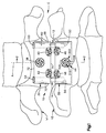
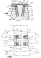
- Figs. 1-11 illustrate apparatus which includes rods interconnected by a pair of plates each secured to a respective vertebra by three screws.
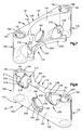
- Fig. 1 illustrates an apparatus 10 for use in retaining bone portions such as cervical vertebrae V1 and V2 of a human spinal column C in a desired stabilized spatial relationship.
- the spinal column C has an axis A which is a vertical axis of the human body.
- the apparatus 10 includes a pair of surgically implantable rods 12 and 14 (Figs. 1 and 2).
- the apparatus 10 also includes first and second members or plates 30 and 32 which engage the rods 12 and 14; three fasteners 38, 40, and 42 for connecting the first plate with the first vertebra V1; and three fasteners 44, 46, and 48 for connecting the second plate with the second vertebra V2.
- the first rod 12 (Fig. 1) is made of a suitable biocompatible material, such as titanium or stainless steel.
- the first rod 12 has an elongate cylindrical configuration and has a circular cross section taken in a plane extending perpendicular to the longitudinal central axis of the first rod.
- the first rod 12 has a smooth outer surface.
- a first end portion of the first rod 12 is formed as a cap 50.
- the first rod 12 also has a second end portion 52 opposite from the first end portion 50.
- the rod 12 has a uniform diameter of about three (3) millimeters throughout its extent except at the cap 50.
- the second rod 14 is identical to the first rod 12.
- the second rod 14 has a first end portion which is formed as a cap 54.
- the second rod 14 also has a second end portion 56 opposite from the first end portion 54.
- the rods 12 and 14 are bendable to a desired configuration to conform to a desired curvature of the spinal column C.
- the rods 12 and 14 together have sufficient strength and rigidity to maintain the vertebrae V1 and V2 in a desired spatial relationship.
- the rods 12 and 14 have a length which is sufficient to enable the rods to span at least the two vertebrae V1 and V2.
- the length of the rods 12 and 14 will depend upon the condition to be corrected and the number of vertebrae to be held in a desired spatial relationship relative to each other by the apparatus 10. If more than two vertebrae are to be held in a desired spatial relationship relative to each other by the apparatus 10, the rods 12 and 14 would be longer and more than two plates, such as the plates 30 and 32, may be used.
- the first plate 30 (Figs. 5 and 6) is made of a suitable biocompatible material, such as titanium or stainless steel.
- the first plate 30 includes a main body portion 60.
- the main body portion 60 of the first plate 30 has a planar outer side surface 62 for facing anteriorly or away from the first vertebra V1.
- the first plate 30 has an arcuate inner side surface 64 for facing posteriorly or toward the first vertebra V1.
- the inner side surface 64 of the first plate 30 may engage the anterior surface of the first vertebra V1 when the first plate is connected with the first vertebra as described below.
- the main body portion 60 of the first plate 30 has a central portion 66 which extends laterally between a first side portion 68 and a second side portion 70 of the first plate. Because the inner side surface 64 of the first plate 30 has an arcuate configuration, the central portion 66 of the first plate is relatively thin (as viewed in a direction from left to right in Fig. 3) as compared to the first side portion 68 and to the second side portion 70.
- the main body portion 60 of the first plate 30 also has first and second end portions 72 and 74.
- the first end portion 72 of the first plate 30 includes a planar first end surface 76 of the first plate 30.
- the second end portion 74 includes a planar second end surface 78 of the first plate 30.
- the second end surface 78 extends parallel to the first end surface 76.
- a first rod passage 80 is formed in the first side portion 68 of the first plate 30.
- the first rod passage 80 is an opening which extends between the first and second end surfaces 76 and 78 of the first plate 30 in a direction parallel to the planar outer side surface 62 of the first plate.
- the first rod passage 80 is defined by a cylindrical surface 81 and tapered pilot surfaces 83 and 84 at opposite ends of the cylindrical surface 81.
- the diameter of the cylindrical surface 81 is slightly greater than the diameter of the first rod 12, so that the first rod and the first plate 30 can be relatively movable.
- the second side portion 70 of the first plate 30 is a mirror image of the first side portion 68.
- a second rod passage 82 is formed in the second side portion 70 of the first plate 30.
- the second rod passage 82 is an opening which extends between the first and second end surfaces 76 and 78 of the first plate 30 in a direction parallel to the planar outer side surface 62 of the first plate.
- the second rod passage 82 extends parallel to the first rod passage 80.
- the second rod passage 82 is defined by a cylindrical surface 85 and tapered pilot surfaces 86 and 87 at opposite ends of the cylindrical surface 85.
- the diameter of the second rod passage 82 is the same as the diameter of the first rod passage 80.
- the diameter of the cylindrical surface 85 is slightly greater than the diameter of the second rod 14, so that the second rod and the first plate 30 can be relatively movable.
- a circular first fastener opening 90 extends through the central portion 66 of the first plate 30.
- the first fastener opening 90 has an axis 92 (Fig. 2) which extends perpendicular to the plane of the outer side surface 62 of the first plate 30.
- the axis 92 extends in a first direction as indicated by the arrow 94, that is, from right to left as viewed in Fig. 2, when the first plate 30 is mounted on the first vertebra V1.
- the first direction 94 extends perpendicular to the axes of the rods 12 and 14.
- the first fastener opening 90 is partially defined by a larger diameter cylindrical surface 96 (Fig. 6) which extends from the outer side surface 62 of the first plate 30 in a direction into the material of the central portion 66 of the first plate.
- the cylindrical surface 96 is centered on the axis 92 of the first fastener opening 90.
- the first fastener opening 90 is partially defined by a smaller diameter cylindrical surface 98 which extends from the inner side surface 64 of the first plate 30 in a direction into the material of the central portion 66 of the first plate to a location spaced radially inward from the surface 96.
- the cylindrical surface 98 is centered on the axis 92 of the first fastener opening 90.
- An annular shoulder surface 100 extends radially (relative to the axis 92) between the cylindrical surfaces 96 and 98.
- the shoulder surface 100 and the larger diameter cylindrical surface 96 define a recess 102 in the outer side surface 62 of the first plate 30.
- the main body portion 60 of the first plate 30 also includes a circular second fastener opening 110 formed at a location adjacent to, but spaced apart from, the first rod passage 80 in the first side portion 68 of the first plate.
- the second fastener opening 110 extends through both the second end surface 78 of the first plate 30 and the outer side surface 62 of the first plate.
- the second fastener opening 110 is partially defined by a larger diameter cylindrical surface 112 (Fig. 6) which extends from the outer side surface of the first plate 30 in a direction into the material of the first side portion 68 of the first plate.
- the cylindrical surface 112 is centered on an axis 114 (Fig. 2) of the second fastener opening 110.
- the cylindrical surface 112 is spaced apart from the first rod passage 80.
- the second fastener opening 110 is partially defined by a smaller diameter cylindrical surface 116 (Fig. 6) which extends from the inner side surface 64 of the first plate 30 in a direction into the material of the first side portion 68 of the first plate, to a location spaced radially inward from the surface 112.
- the cylindrical surface 116 is centered on the axis 114 of the second fastener opening 110.
- An annular shoulder surface 118 extends radially (relative to the axis 114) between the cylindrical surfaces 112 and 116.
- the shoulder surface 118 and the larger diameter cylindrical surface 112 define a recess 120 in the outer side surface 62 of the first plate 30.
- the axis 114 of the second fastener opening 110 extends transverse to the axis 92 of the first fastener opening 90. Specifically, the axis 114 (Fig. 3) of the second fastener opening 110 converges with the axis 92 of the first fastener opening 90 as viewed in a transverse plane at right angles to the vertical axis A, as can be seen from Fig. 3. In the illustrated embodiment, the axis 114 converges at an angle of about 10° with the axis 92 as viewed in this transverse plane.
- the axis 114 of the second fastener opening 110 also converges with the axis 92 of the first fastener opening 90 as viewed in the sagittal plane, as can be seen in Fig. 2.
- the axis 114 converges at an angle of 45° with the axis 92 as viewed in the sagittal plane. It is contemplated that the angle of convergence as viewed in the sagittal plane is preferably in the range of from about 30° to about 60°.
- the main body portion 60 of the first plate 30 also includes a circular third fastener opening 130 formed at a location adjacent to, but spaced apart from, the second rod passage 82 in the second side portion 70 of the first plate.
- the third fastener opening 130 extends through both the second end surface 78 of the first plate 30 and the outer side surface 62 of the first plate.
- the third fastener opening 130 is partially defined by a larger diameter cylindrical surface 132 (Fig. 6) which extends from the outer side surface 62 of the first plate 30 in a direction into the material of the second side portion 70 of the first plate.
- the cylindrical surface 132 is centered on an axis 134 (Fig. 4) of the third fastener opening 130.
- the cylindrical surface 132 is spaced apart from the second rod passage 82.
- the third fastener opening 130 is partially defined by a smaller diameter cylindrical surface 136 (Fig. 6) which extends from the inner side surface 64 of the first plate 30 in a direction into the material of the second side portion 70 of the first plate, to a location spaced radially inward from the surface 32.
- the cylindrical surface 136 is centered on the axis 134 of the third fastener opening 130.
- An annular shoulder surface 138 extends radially (relative to the axis 134) between the cylindrical surfaces 132 and 136.
- the shoulder surface 138 and the larger diameter cylindrical surface 132 define a recess 140 in the outer side surface 62 of the first plate 30.
- the axis 134 (Fig. 3) of the third fastener opening 130 is coplanar with and extends parallel to the axis 114 of the second fastener opening 110.
- the axis 134 of the third fastener opening 130 extends transverse to the axis 92 of the first fastener opening 90.
- the axis 134 of the third fastener opening 130 converges with the axis 92 of the first fastener opening 90 as viewed in a transverse plane at right angles to the vertical axis A, as can be seen from Fig. 3.
- the axis 134 converges with the axis 92 at an angle of 10° as viewed in this transverse plane.
- the axis 134 of the third fastener opening 130 also converges with the axis 92 of the first fastener opening 90 as viewed in the sagittal plane, as can be seen from Fig. 2.
- the axis 134 converges with the axis 92 at an angle of 45° as viewed in the sagittal plane. It is contemplated that this angle of convergence as viewed in the sagittal plane could be in the range of from about 30° to about 60°.
- the first plate 30 includes a lip portion or lip 150 which is formed as one piece with the main body portion 60 of the first plate.
- the lip 150 best seen in Figs. 2 and 5, projects from the second end portion 74 of the main body portion 60 of the first plate 30.
- the lip 150 projects in the first direction 94 (Fig. 2) when the first plate 30 is mounted on the first vertebra V1.
- the lip 150 has a planar configuration as viewed in the first direction 94, for example, as seen in Fig. 2.
- the lip 150 has an arcuate configuration, as can be seen in Fig. 5, when viewed in a direction parallel to the plane of the outer side surface 62 of the first plate 30.
- the arcuate configuration of the lip 150 generally follows the arcuate configuration of the inner side surface 64 of the main body portion 60 of the first plate 30.
- the lip 150 extends continuously between the first and second side portions 68 and 70 of the first plate 30.
- the lip 150 may be discontinuous at one or more locations along the width of the plate 30.
- the lip 150 has an outer end surface 152 (Fig. 2) which is formed as an extension of the second end surface 78 of the main body portion 60 of the first plate 30.
- An opposite inner end surface 154 (Figs. 2 and 5) of the lip 150 extends parallel to the outer end surface 152.
- the lip 150 also has an inner side surface 156 which extends between the inner and outer end surfaces 154 and 152 of the lip 150.
- the second and third fastener openings 110 and 130 extend partially through the lip 150.
- the second fastener opening 110 as can be seen in Fig. 2, extends through the corner between, or intersection of, the lip 150 and the main body portion 60 of the first plate 30.
- the third fastener opening 130 also extends through the corner between, or intersection of, the lip 150 and the main body portion 60 of the first plate 30.
- the second plate 32 (Fig. 7) is generally similar in configuration to the first plate 30 (Fig. 5).
- the second plate 32 (Fig. 7) is configured, however, so that the head ends of fasteners received in certain fastener openings in the second plate are engageable with the rods 12 and 14 disposed in rod passages in the second plate. This engagement can block movement of the second plate 32 relative to the rods 12 and 14, in a manner described below.
- the second plate 32 includes a main body portion 160 which has a planar outer side surface 162 for facing anteriorly or away from the vertebra V2.
- the main body portion 160 also has an arcuate inner side surface 164 for facing posteriorly or toward the second vertebra V2.
- the inner side surface 164 of the second plate 32 may engage the anterior surface of the second vertebra V2 when the second plate is connected with the second vertebra as described below.
- the main body portion 160 has a central portion 166 which extends laterally between a first side portion 168 and a second side portion 170 of the second plate 32. Because the inner side surface 164 of the second plate 32 has an arcuate configuration, the central portion 166 of the second plate 32 is relatively thin (as viewed in a direction from left to right in Fig. 4) as compared to the first side portion 168 and to the second side portion 170.
- the main body portion 160 of the second plate 32 also has first and second end portions 172 and 174.
- the first end portion 172 of the second plate 32 includes a planar first end surface 176 of the second plate.
- the second end portion 174 of the second plate 32 includes a planar second end surface 178 of the second plate.
- the second end surface 178 extends parallel to the first end surface 176.
- a first rod passage 180 is formed in the first side portion 168 of the second plate 32.
- the first rod passage 180 is an opening which extends between the first and second end surfaces 176 and 178 in a direction parallel to the planar outer side surface 162 of the second plate 32.
- the first rod passage 180 is defined by a cylindrical surface 181 and tapered pilot surfaces 183 and 184 at opposite ends of the cylindrical surface 181.
- the diameter of the cylindrical surface 181 is slightly greater than the diameter of the first rod 12.
- a second rod passage 182 is formed in the second side portion 170 of the second plate 32.
- the second rod passage 182 is an opening which extends between the first and second end surfaces 176 and 178 in a direction parallel to the planar outer side surface 162 of the second plate 32.
- the second rod passage 182 extends parallel to and has the same diameter as the second rod passage as first rod passage 180.
- the second rod passage 182 is defined by a cylindrical surface 185 and tapered pilot surfaces 186 and 187 at opposite ends of the cylindrical surface 185.
- the diameter of the cylindrical surface 185 is slightly greater than the diameter of the second rod 14.
- a circular first fastener opening 190 extends through the central portion 166 of the second plate 32.
- the first fastener opening 190 has an axis 192 (Figs. 2 and 4) which extends perpendicular to the plane of the outer side surface 162 of the second plate 32.
- the axis 192 extends in the first direction 94 when the second plate 32 is mounted on the second vertebra V2.
- the first fastener opening 190 is partially defined by a larger diameter cylindrical surface 196 (Fig. 8) which extends from the outer side surface 162 of the second plate 32 in a direction into the material of the central portion 166 of the second plate.
- the cylindrical surface 196 is centered on the axis 192 of the first fastener opening 190.
- the first fastener opening 190 is partially defined by a smaller diameter cylindrical surface 198 which extends from the inner side surface 164 of the second plate 210 in a direction into the material of the central portion 166 of the second plate, to a location spaced radially inward from the surface 196.
- the cylindrical surface 198 is centered on the axis 192 of the first fastener opening 190.
- An annular shoulder surface 200 extends radially (relative to the axis 192) between the cylindrical surfaces 196 and 198.
- the shoulder surface 200 and the larger diameter cylindrical surface 196 define a recess 202 in the outer side surface 162 of the second plate 32.
- the main body portion 160 of the second plate 32 also includes a circular second fastener opening 210 formed at a location adjacent to and intersecting the first rod passage 180 in the first side portion 168 of the second plate.
- the second fastener opening 210 extends through both the second end surface 178 of the second plate 32 and the outer side surface 162 of the second plate.
- the second fastener opening 210 is partially defined by a larger diameter cylindrical surface 212 (Fig. 8) which extends from the outer side surface 262 of the second plate 32 in a direction into the material of the first side portion 168 of the second plate.
- the cylindrical surface 212 is centered on an axis 214 (Figs. 2 and 4) of the second fastener opening 210.
- the cylindrical surface 212 intersects the cylindrical surface 181 which defines the first rod passage 180.
- the second fastener opening 210 overlaps a portion of the first rod passage 180.
- the second fastener opening 210 is partially defined by a smaller diameter cylindrical surface 216 which extends from the inner side surface 264 of the second plate 32 in a direction into the material of the first side portion 168 of the second plate, to a location spaced radially inward from the surface 212.
- the cylindrical surface 216 is centered on the axis 214 of the second fastener opening 210.
- An annular shoulder surface 218 extends radially (relative to the axis 214) between the cylindrical surfaces 212 and 216.
- the shoulder surface 218 and the larger diameter cylindrical surface 212 define a recess 220 in the outer side surface 262 of the second plate 32.
- the axis 214 of the second fastener opening 210 extends transverse to the axis 192 of the first fastener opening 190. Specifically, the axis 214 of the second fastener opening 210 converges with the axis 192 of the first fastener opening 190 as viewed in a transverse plane at right angles to the vertical axis A, as can be seen from Fig. 4. In the illustrated embodiment, the axis 214 converges with the axis 192 at angle of about 10° as viewed in this transverse plane.
- the axis 214 of the second fastener opening 210 also converges with the axis 192 of the first fastener opening 190 as viewed in the sagittal plane, as can be seen in Fig. 2.
- the axis 214 converges with the axis 192 at an angle of 45° as viewed in the sagittal plane. It is contemplated that this angle of convergence could be in the range of from about 30° to about 60° as viewed in the sagittal plane.
- the main body portion 160 of the second plate 32 also includes a circular third fastener opening 230 formed at a location adjacent to and intersecting the second rod passage 182 in the second side portion 170 of the second plate.
- the third fastener opening 230 extends through both the second end surface 178 of the second plate 32 and the outer side surface 162 of the second plate.
- the distance between the third fastener opening 230 in the second plate 32 and the second fastener opening 210 in the second plate is slightly more than the distance between the third fastener opening 130 in the first plate 30 and the second fastener opening 110 in the first plate.
- the third fastener opening 230 is partially defined by a larger diameter cylindrical surface 232 (Fig. 8) which extends from the outer side surface 262 of the second plate 32 in a direction into the material of the second side portion 170 of the second plate.
- the cylindrical surface 232 is centered on an axis 234 (Fig. 4) of the third fastener opening 230.
- the cylindrical surface 232 intersects the cylindrical surface 185 which defines the second rod passage 182.
- the third fastener opening 230 overlaps a portion of the second rod passage 182.
- the third fastener opening 230 is partially defined by a smaller diameter cylindrical surface 236 (Fig. 8) which extends from the inner side surface 264 of the second plate 32 into the material of the second side portion 170 of the second plate to a location spaced radially inward from the surface 232.
- the cylindrical surface 236 is centered on the axis 234 of the third fastener opening 230.
- An annular shoulder surface 238 extends radially (relative to the axis 234) between the cylindrical surfaces 232 and 236.
- the shoulder surface 238 and the larger diameter cylindrical surface 232 define a recess 240 in the outer side surface 162 of the second plate 32.
- the axis 234 of the third fastener opening 230 is coplanar with and extends parallel to the axis 214 of the second fastener opening 210.
- the axis 234 of the third fastener opening 230 extends transverse to the axis 192 of the first fastener opening 190.
- the axis 234 of the third fastener opening 230 converges with the axis 192 of the first fastener opening 190 as viewed in a transverse plane at right angles to the vertical axis A, as can be seen from Fig. 4.
- the axis 234 converges with the axis 192 at an angle of about 10° as viewed in this transverse plane.
- the axis 234 of the third fastener opening 230 also converges with the axis 192 of the first fastener opening 190 as viewed in the sagittal plane, as can be seen from Fig. 2.
- the axis 234 converges with the axis 192 at an angle of 45°. It is contemplated that this angle of convergence as viewed in the sagittal plane could be in the range of from about 30° to about 60°.
- the second plate 32 includes a lip portion or lip 250 which is formed as one piece with the main body portion 160 of the second plate.
- the lip 250 best seen in Figs. 4 and 7, projects from the second end portion 174 of the main body portion 160 of the second plate 32.
- the lip 250 projects in the first direction 94 (Fig. 2) when the second plate 32 is mounted on the second vertebra V2.
- the lip 250 has a planar configuration as viewed in the first direction 94, for example, as seen in Fig. 2.
- the lip 250 as viewed in a direction parallel to the plane of the outer side surface 162 of the second plate 32, has an arcuate configuration generally following the arcuate configuration of the inner side surface 164 of the main body portion 160 of the second plate 32.
- the lip 250 extends continuously between the first and second side portions 168 and 170 of the second plate 32.
- the lip 250 may be discontinuous at one or more locations along the width of the second plate 32.
- the lip 250 has an outer end surface 252 (Fig. 2) which is formed as an extension of the second end surface 178 of the main body portion 160 of the second plate 32.
- An opposite inner end surface 254 (Figs. 2 and 8) of the lip 250 extends parallel to the outer side surface 252.
- the lip 250 also has an inner side surface 256 which extends between the inner and outer end surfaces 252 and 254 of the lip 250.
- the second and third fastener openings 210 and 230 extend partially through the lip 250.
- the second fastener opening 210, as well as the third fastener opening 230 extend through the corner between, or intersection of, the lip 250 and the main body portion 160 of the second plate 32.
- the fasteners 38, 40, 42, 44, 46, and 48 which connect the first plate 30 with the first vertebra V1 and the second plate 32 with the second vertebra V2, are identical to each other. Because the fasteners 38-48 are identical, only the fastener 40 is described herein in detail.
- the fastener 40 (Fig. 3) includes a sleeve 300 and an expander 310.
- the sleeve 300 has a hollow, elongate shank portion 302 centered on a longitudinal central axis 304 of the fastener 40.
- the shank portion 302 defines a cylindrical central opening 308 in the sleeve 300.
- a coarse external helical thread convolution 306 is formed on the outer peripheral surface of the shank portion 302 of the sleeve 300.
- the shank portion 302 of the sleeve 300 is radially and axially slotted so that the shank portion is expandable radially.
- a series of projections are formed on the inner surface of the sleeve 300 for engagement by the expander 310 to expand the shank portion 302 of the sleeve in a manner described below.
- a head end portion 314 of the sleeve 300 has a cylindrical outer side surface 316.
- An annular lip or rim 318 extends around the head end portion 314 of the sleeve 300 and projects radially outward from the outer side surface 316.
- the head end portion 314 of the sleeve 300 has a conical inner side surface 320 and a conical inner side surface 322.
- the conical inner side surface 322 merges with an internal thread convolution 324 formed on the sleeve 300.
- the head end portion 314 of the sleeve 300 is radially and axially slotted to define four segments 326 of the head end portion.
- the four segments 326 are movable radially relative to each other and to the axis 304 of the fastener 40 so that the head end portion 314 of the sleeve 300 is expandable radially.
- the expander 310 has a head end portion 340 and a shank portion 342.
- An inner end 344 of the shank portion 342 of the expander 310 is slightly larger in diameter than the cylindrical central opening 308 in the sleeve 300.
- the head end portion 340 of the expander 310 has an X-shaped driver slot 346 for receiving a driving tool for rotating the expander relative to the sleeve 300.
- the head end portion 340 has a conical outer side surface 348 and a conical outer side surface 350.
- the conical outer side surface 350 on the head end portion 340 of the expander 310 has a different angle of taper than does the conical inner side surface 322 on the head end portion 314 of the sleeve 300.
- the conical outer side surface 350 on the head end portion 340 of the expander 310 merges with an external thread convolution 352 formed on the expander 310.
- the external thread convolution 352 on the expander 310 screws into the internal thread convolution 324 on the sleeve 300.
- the rods 12 and 14 may first be assembled with the plates 30 and 32. Specifically, the first rod 12 is inserted through the first rod passage 80 in the first plate 30 and through the first rod passage 180 in the second plate 32. One of the tapered pilot surfaces 83 and 84 on the first plate 30, and one of the tapered pilot surfaces 183 and 184 on the second plate 32, guide insertion of the first rod 12. The second rod 12 is inserted through the second rod passage 82 in the first plate 30 and through the second rod passage 182 in the second plate 32. One of the tapered pilot surfaces 86 and 87 on the first plate 30, and one of the tapered pilot surfaces 186 and 187 on the second plate 32, guide insertion of the second rod 14.
- the assembly of the rods 12 and 14 and the plates 30 and 32 is then positioned over the exposed anterior surface of the spinal column C.
- the first plate 30 (Fig. 2) is positioned adjacent to the first vertebra V1 so that the first end surface 154 on the lip 150 of the first plate engages a lower surface 360 on the first vertebra V1.
- the lower surface 360 on the first vertebra V1 faces toward the second vertebra V2.
- the second plate 32 is positioned adjacent to the second vertebra V2 so that the first end surface 254 on the lip 250 of the second plate engages an upper surface 362 on the second vertebra V2.
- the upper surface 362 on the second vertebra V2 faces toward the first vertebra V1.
- a suitable drill guide and drill (not shown) are used to drill fastener openings in the first vertebra V1 and in the second vertebra V2.
- the fasteners 38, 40 and 42 are inserted to connect the first plate 30 with the first vertebra.
- the insertion and securing of the fastener 40, although not necessarily performed first, will be described as exemplary.
- the sleeve 300 of the fastener 40 is inserted through the second fastener opening 110 in the first plate 30.
- the sleeve 300 of the fastener 40 is threaded into the drilled opening in the vertebra V1 in a known manner (not shown) to fix the sleeve in position in the vertebra V1.
- the unexpanded head portion 314 of the sleeve 300 is disposed in the recess 120 in the first plate 30.
- the expander 310 of the fastener 40 is then inserted into the sleeve 300.
- the externally threaded portion 352 of the expander 310 is screwed into the internal threads 324 on the sleeve 300.
- the inner end portion 344 of the expander 310 causes the shank portion 302 of the sleeve to expand radially outward, helping to lock the sleeve in place in the vertebra V1.
- the head portion 340 of the expander 310 engages the head portion 314 of the sleeve 300.
- the head portion 340 of the expander 310 wedges the locking segments 326 on the sleeve 300 radially outward into engagement with the first plate 30 to rigidly lock the fastener 40 in position relative to the first plate.
- the head of the fastener 40 is adjacent to the lip 150.
- the remaining fasteners 38 and 42 for the first plate 30 are similarly secured to the vertebra V1 and are rigidly locked to the first plate.
- the heads of the fasteners 38 and 42 are adjacent to the lip 150.
- the first plate 30 is securely connected with the first vertebra V1.
- the fasteners 44, 46 and 48 are similarly used to connect the second vertebra V2 and the second plate 32.
- the heads of the fasteners 44, 46 and 48 are adjacent to the lip 250.
- the fasteners 44, 46 and 48 are rigidly locked to the second plate 32 and the second plate 32 is securely connected with the second vertebra V2.
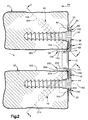
- the fastener 40 (as well as the fastener 42, not shown in Fig. 2) extends at an angle (upward as viewed in Fig. 2) to the lip 150. Accordingly, when the fasteners 40 and 42 are tightened into the first vertebra V1, the fasteners tend to draw the lip 150 of the first plate 30 tightly against the surface 360 of the vertebra, that is, in an upward direction as viewed in Fig. 2. At the same time, the fasteners 40 and 42, as well as the fastener 38, tend to draw the main body portion 60 of the first plate 30 tightly against the anterior surface of the first vertebra V1, that is, in a direction to the left as viewed in Fig. 2. Accordingly, it can be seen that tightening the fasteners 38, 40 and 42 tends to draw the first plate 30 in two directions against the first vertebra V1.
- the first fastener 38 has a longitudinal central axis which is coincident with the axis 92 of the first fastener opening 90 when the first fastener 38 is disposed in the first fastener opening 90 in the first plate 30.
- the longitudinal central axis 304 of the second fastener 40 is coincident with the axis 114 of the second fastener opening 110.
- the axis 92 of the first fastener opening 90 and the axis 114 of the second fastener opening 110 converge at an acute angle as viewed in the sagittal plane (Fig. 2). Therefore, the longitudinal axis of the first fastener 38 and the longitudinal axis 304 of the second fastener 40 converge at an acute angle as viewed in the sagittal plane (Fig. 2) when the first and second fasteners 38 and 40 connect the first plate 30 with the first vertebra V1.
- the axis of the first fastener 38 and the axis 304 of the second fastener 40 converge at an angle of about 45° as viewed in the sagittal plane. It is contemplated that this angle of convergence in the sagittal plane is preferably in the range of from about 30° to about 60°.
- the longitudinal central axis of the third fastener 42 is coincident with the axis 134 of the third fastener opening 130.
- the axis 92 of the first fastener opening 90 and the axis 134 of the third fastener opening 110 converge at an acute angle as viewed in the sagittal plane (Fig. 2). Therefore, the longitudinal axis of the first fastener 38 and the longitudinal axis of the third fastener 42 converge at an acute angle as viewed in the sagittal plane (Fig. 2) when the first and third fasteners 38 and 42 connect the first plate 30 with the first vertebra V1.
- the axis of the first fastener 38 and the axis of the third fastener 42 converge at an angle of about 45° as viewed in the sagittal plane. It is contemplated that this angle of convergence in the sagittal plane is preferably in the range of from about 30° to about 60°.
- the second plate 32 is, in a similar manner, secured in position relative to the second vertebra V2. Tightening the fasteners 44, 46 and 48 tends to draw the second plate 32 in two directions against the second vertebra V2.
- the axis of the first fastener 44 and the axis of the second fastener 46 converge at an acute angle as viewed in the sagittal plane (Fig. 2).
- the axis of the first fastener 44 and the axis of the third fastener 48 converge at an acute angle as viewed in the sagittal plane (Fig. 2).
- these axes converge at an angle of about 45° as viewed in the sagittal plane. It is contemplated that this angle of convergence in the sagittal plane could be in the range of from about 30° to about 60°.
- the outer fasteners 46 and 48 secure the second plate and the second vertebra.
- the fasteners 46 and 48 also serve to interlock the second plate 32 with the rods 12 and 14. This is because the locking segments 326 on the sleeves 300 of the fasteners 46 and 48 (Fig. 4) move radially outward into engagement with the rods 12 and 14, respectively, when each fastener's expander is fully screwed into the fastener's sleeve.
- the engagement between the fasteners 46 and 48 and the rods 12 and 14 blocks movement of the fasteners 46 and 48 relative to the rods.
- the first plate 30, in contrast, is movable relative to the rods 12 and 14, because the second and third fastener openings 110 and 130 are spaced apart from the rod passages 80 and 82. Therefore, the first plate 30 is movable relative to the second plate 32.
- the first vertebra V1 is movable vertically downward relative to the second vertebra V2.
- This relative movement allows for the maintaining of a load on bone graft placed between the vertebrae V1 and V2. If the first plate 30 were not movable vertically downward relative to the second plate 32, then the distance between the vertebrae V1 and V2 would be fixed. If bone graft were placed between the vertebrae V1 and V2 and the bone graft resorbed sufficiently, the bone graft could possibly shrink out of engagement with one or both of the vertebrae V1 and V2.
- Allowing relative movement of the plates 30 and 32 can help to maintain a load on bone graft placed between the vertebrae V1 and V2 and maintains the vertebrae in contact with the bone graft to facilitate bone growth.
- the lips 150 and 250 on the plates 30 and 32 are, preferably, configured so that the lips do not contact bone graft placed between the vertebrae.
- a dynamic (movable) plate such as the plate 30.
- two locking plates identical to the plate 32 can be used in the same apparatus 10.
- a system is illustrated in Fig. 9.
- the upper plate 32 (Fig. 9) is fixed in position relative to the vertebra V1 and to the rods 12 and 14.
- the lower plate 32 (Fig. 9) is fixed in position relative to the vertebra V2 and to the rods 12 and 14. Accordingly, the apparatus 10 (Fig. 9) blocks relative movement between the vertebrae V1 and V2.
- the rods 12 and 14 are located at the opposite sides of the plates 30, 32 where the plates curve around the vertebra, the rods 12 and 14 may have a relatively larger diameter, than if the rods 12 and 14 were otherwise located, without creating an excessively high profile for the apparatus 10. This minimizes the chance of contact between the apparatus 10 and parts of the body such as the esophagus. Also, since the fasteners are located between the rods, the fasteners are more easily installed than if the fasteners were otherwise located, for example, if the rods were located between the fasteners.
- Figs. 10 and 11 illustrate a plate 30a which is constructed in accordance with another embodiment of the present invention.
- the plate 30a can be substituted, in the apparatus 10, for the plate 30.
- the plate 30a is generally similar to the plate 30 (Figs. 5 and 6), and similar reference numerals are used to designate similar parts, with the suffix "a" added in Figs. 10 and 11 for clarity.
- a pair of set screws 370 are provided for engaging the rods 12 and 14 to block movement of the plate, and thereby its associated bone portion, relative to the rods.
- the outer side surface 62a of the plate 30a is recessed at 372 adjacent to the second rod passage 82a.
- a seat 374 extends inwardly from the recess 372 to a threaded opening 376.
- An inner end portion 378 of the opening 376 intersects with the second rod passage 82a.
- a second threaded opening 380 intersects the first rod passage 80a.
- fasteners such as the fasteners 38-42 are inserted through fastener openings 90a, 110a, and 130a in the plate 30a, to secure the plate to its associated bone portion.
- the head end portions of the fasteners for the plate 30a do not engage the rods 12 and 14, and do not clamp the rods against the plate 30a.
- a set screw 370 is threaded into the opening 376.
- An inner end portion 382 of the set screw 370 engages the cylindrical outer surface of the second rod 14.
- the engagement of the set screw 370 with the second rod 14 clamps the rod against the second side portion 70a of the plate 30a.
- Another set screw 370 is threaded into the opening 380 to engage the first rod 12 and clamp the first rod against the first side portion 68a of the plate 30a.
- the set screws 370, the rods 12 and 14, and the plate 30a are interlocked.
- the plate 30a is not movable relative to (along the length of) the rods 12 and 14. Because the plate 30a is fixed to its associated bone portion, then the bone portion also is not movable relative to the rods 12 and 14.
- a portion of the lip 150a is removed at the location of the fastener openings 110a and 130a, to provide better visibility.
- This provides two lip segments 151 and 153 at the side portions 68a and 70a, respectively, of the plate 30a.
- a portion of the lip 150a also is removed at the lateral center of the plate 30a, and a notch 384 is provided in the plate 30a, again to increase visibility.
- the lip segments 151 and 153 are spaced apart on opposite sides of the longitudinal axis, or centerline, of the plate 30a.
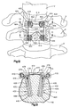
- Figs. 12-22 illustrate apparatus which include rods interconnected by a pair of plates each secured to a respective vertebra by two screws.
- Fig. 12 illustrates an apparatus which includes a pair of surgically implantable rods 410 for stabilizing a human spinal column C.
- the rods 410 are connected to anterior portions of cervical vertebrae V of the spinal column by plates or members 412 and 414.
- Each rod 410 is elongate and has a circular cross section taken in a plane extending perpendicular to the longitudinal central axis of the rod.
- the rods 410 are bendable in any desired plane to conform to a desired curvature of the spinal column C.
- the rods 410 have sufficient strength and rigidity to maintain the vertebrae V in the desired relationship.
- the rods 410 are made of a biocompatible material such as titanium or stainless steel.
- Each of the rods 410 has a length which is at least sufficient to enable the rod to span at least two of the cervical vertebrae V. In the embodiment of the invention illustrated in Fig. 12, the rods 410 span two vertebrae V. Of course, the length of the rods 410 will depend upon the condition to be corrected and the number of vertebrae V to be held in a desired spatial relationship relative to each other by the rods 410.
- the plate 412 is connected to a vertebra V by fasteners 420 (Fig. 13).
- the fasteners 420 also fix or lock the rods 410 relative to the plate 412 to prevent relative movement between the rods 410 and the plate.
- the plate 414 is connected to a vertebra V by fasteners 422 (Fig. 16).
- the fasteners 422 permit relative movement between the plate 414 and the rods 410. Therefore, the plate 414 is considered a dynamic plate.
- Each rod 410 terminates in a cap 424 engageable with the plate 414.
- the caps 424 prevent movement of the plate 414 relative to the rods 410 in a direction away from the plate 412, while allowing movement of the plate 414 in a direction toward the plate 412.
- Each of the fasteners 420 (Figs. 13 and 14) includes a sleeve 430 and an expander 432 located within the sleeve.
- the sleeve 430 has an axially extending central opening 434 for receiving the expander 432.
- the sleeve 430 includes a coarse external helical thread convolution 436 for engaging a vertebra V.
- the sleeve 430 (Fig. 14) has a head end portion 438 with a cylindrical outer side surface 440.
- An annular lip or rim 442 extends around the head end portion 438 of the sleeve 430 and projects radially outward from the cylindrical outer side surface 440.
- the head end portion 438 of the sleeve 430 is radially and axially slotted to define four segments 444 (Fig. 12) of the head end portion 438.
- the four segments 444 are movable radially outward relative to each other.
- the radially and axially extending slots in the head end portion 438 receive a driving tool for threading the sleeve 430 into a vertebra.
- An end portion 448 (Fig. 14) of the sleeve 430 opposite from the head end portion 438 is radially and axially slotted to permit radially outward expansion of the end portion 448.
- the opening 434 of the sleeve 430 has a first diameter located along a central portion 450 of the sleeve 430 and a second diameter smaller than the first diameter located adjacent the end portion 448.
- the sleeve 430 has an internally threaded portion 452 between the central portion 450 and the head end portion 438.
- the head end portion 438 has a conical-shaped surface 454 that tapers from a larger diameter to a smaller diameter adjacent another conical-shaped surface 456.
- the surface 456 interconnects the surface 454 and the threaded portion 452.
- the surface 456 tapers from the larger diameter adjacent the surface 454 to the smaller diameter of the threaded portion 452.
- the expander 432 has a rod-shaped portion 460 for extending in the opening 434.
- the rod portion 460 has a diameter which is approximately equal to the diameter of the opening 434 in the central portion 450 of the sleeve.
- the rod portion 460 engages the interior of the end portion 448 of the sleeve 430 and causes the end portion 448 to expand and help retain the fastener 420 in the vertebra V.
- the expander 432 has a head end portion 462 with an X-shaped driver slot for receiving a driving tool for rotating the expander relative to the sleeve 430.
- the head end portion 462 has a tapering surface 464 for engaging the tapering surface 454 of the sleeve 430.
- the expander 432 includes a threaded portion 466 for threadably engaging the threaded portion 452 of the sleeve 430.
- the tapering surface 464 of the expander 432 engages the tapering surface 454 of the sleeve 430 to move the four segments 444 radially outward. Therefore, the head end portion 438 of the sleeve 430 expands.
- the member or plate 412 (Figs. 13-15) is made of a suitable biocompatible material, such as titanium or stainless steel.
- the plate 412 includes a surface 470 for engaging an anterior surface of the vertebra V and a surface 472 opposite from the surface 470 for facing away from the vertebra V.
- the plate 412 has generally parallel openings 474 for receiving the rods 410.
- Slots 475 (Fig. 15) extend from side surfaces 476 of the plate 412 and intersect the openings 474.
- the slots 475 define a pair of axially spaced arcuate surfaces that engage portions of the rod 410 at axially spaced locations.
- the plate 412 (Figs. 14 and 15) has a pair of openings 478 for receiving the fasteners 420 located adjacent the side surfaces 470 and intersecting the openings 474.
- the openings 478 have axes 479 that extend at an angle relative to each other.
- Each of the fastener openings 478 is partially defined by a larger diameter cylindrical surface 480 which extends parallel to the axis 479 of the fastener opening.
- the fastener opening 478 is partially defined by a smaller diameter cylindrical surface 482 which extends parallel to the axis 479 of the opening.
- An annular shoulder surface 484 extends radially between the surfaces 480 and 482.
- the shoulder surface 484 defines a seat or recess in the opening 478 against which the rim 442 of the sleeve 430 engages.
- the axes 479 of the openings 478 extend at an angle relative to each other so that the fasteners 420 extend at an angle to each other.
- the plate 412 When the plate 412 is to be connected to the anterior portion of the cervical vertebra V, it is positioned on the anterior portion of the cervical vertebra with the surface 470 facing the anterior portion of the vertebra V and the rods 410 extending through the openings 474.
- the sleeves 430 of the fasteners 420 are placed through the openings 478 in the plate 412 and threaded into the vertebra V.
- the sleeves 430 are threaded into the vertebra V until the rim 442 of the sleeve engages the shoulder surface 484 and presses the surface 470 of the plate 412 against the vertebra V.
- the expanders 432 are threaded into the sleeves 430 to cause the head end portions 438 to expand so that the segments 444 expand radially outward into engagement with the cylindrical surfaces 480 of the openings 478.
- the head end portion 438 also expands into engagement with the rod 410 and clamps the rod in the opening 474. Accordingly, the fasteners 420, the plate 412, and the rods 410 are prevented from moving relative to each other.
- the fasteners 420 secure the plate 412 to the vertebra V.
- the plate 412 is also fixed in position relative to the rods 410, as described above. Accordingly, the vertebra connected to the plate 412 is fixed in position relative to the rods 410.
- Each of the fasteners 422 which secure the plate 414 to a vertebra V includes a sleeve 490 and an expander 492 located within the sleeve.
- Each fastener 422 has a longitudinal central axis 493.
- the sleeve 490 has an axially extending central opening 494 for receiving the expander 492.
- the sleeve 490 includes a coarse external helical thread convolution 496 for engaging a vertebra V.
- the sleeve 490 (Fig. 17) has a head end portion 498 with a part spherical outer side surface 500.
- the head end portion 498 of the sleeve 490 is radially and axially slotted to define four segments 504 (Fig. 12) of the head end portion 498.
- the four segments 504 are movable radially inward and outward relative to each other so that the head end portion 498 is expandable and collapsible.
- the radially and axially extending slots in the head end portion 498 receive a driving tool for threading the sleeve 490 into a vertebra V.
- An end portion 508 (Fig.
- the head end portion 498 of the fastener 422 has a surface 548 facing away from the end portion 508.
- the opening 494 of the sleeve 490 has a first diameter located along a central portion 510 of the sleeve 490 and a second diameter smaller than the first diameter located adjacent the end portion 508.
- the sleeve 490 has an internally threaded portion 512 between the central portion 450 and the head end portion 498.
- the head end portion 498 has a conical-shaped surface 514 that tapers from a larger diameter to a smaller diameter adjacent another conical-shaped surface 516.
- the surface 516 interconnects the surface 514 and the threaded portion 512.
- the surface 516 tapers from the larger diameter adjacent the surface 514 to the smaller diameter of the threaded portion 512.
- the expander 492 has a rod-shaped portion 520 for extending into the opening 494.
- the rod portion 520 has a diameter which is approximately equal to the diameter of the opening 494 in the central portion 510 of the sleeve 490.
- the rod portion 520 engages the interior of the end portion 508 of the sleeve 490 and causes the end portion 508 to expand and help retain the fastener 422 in the vertebra V.
- the expander 492 has a head end portion 521 with an X-shaped driver slot for receiving a driving tool for rotating the expander relative to the sleeve 490.
- the head end portion 522 has a tapering surface 524 for engaging the tapering surface 514 of the sleeve 490.
- the expander 492 includes a threaded portion 526 for threadably engaging the threaded portion 512 of the expander 490.
- the tapering surface 524 of the expander 492 engages the tapering surface 514 of the sleeve 490 to move the four segments 504 radially outward. Therefore, the head end portion 498 of the sleeve 490 expands.
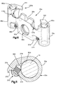
- the member or plate 414 (Figs. 16-18) is made of a suitable biocompatible material, such as titanium or stainless steel.
- the plate 414 includes a surface 530 for engaging an anterior surface of the vertebra V and a surface 532 opposite from the surface 530 for facing away from the vertebra V.
- the plate 414 has generally parallel rod openings 534 for receiving the rods 410.
- the plate 414 has a pair of fastener openings 538 for receiving the fasteners 422 located adjacent side surfaces 536 of the plate 414.
- the openings 538 have axes 539 extending at an angle to each other.
- Each fastener opening 538 is partially defined by a part spherical surface 540 (Figs. 17-21) centered on the axis 539.
- the part spherical surface 540 defines a seat or recess in the opening 538 against which the part spherical surface 500 of the sleeve 490 engages.
- the part spherical recess 540 has a major diameter 542.
- a first portion 544 of the recess 540 is located on one side of the major diameter 542 and adjacent the surface 532 of the plate 414.
- a second portion 546 of the recess 540 is located on the other side of the major diameter 542 and adjacent the surface 530 of the plate 414.
- the plate 414 When the plate 414 is to be connected to a vertebra V, the plate 414 is placed on the vertebra V with the surface 530 engaging the anterior portion of the vertebra V and the rods 410 extending through the openings 534.
- the sleeves 490 are threaded into the vertebra V through the openings 538 in the plate 414.
- the segments 504 As the head end portion 498 of the sleeve 490 enters the opening 538 in the plate 414 the segments 504 are compressed radially inward then expand radially outward.
- the surfaces 548 on the head end portions 498 are located in the first portions 544 of the recesses 540 when the head end portions 498 are received in the recesses. Because the major diameter 542 of each recess 540 is spaced inward from the outer surface 532 of the plate 414, the expanded fasteners 422 resist movement out of the recesses in the plate.
- the expander 492 is threaded into the sleeve 490 and causes the head end portion 498 to expand into engagement with the opening 538 and prevent relative movement between the plate 414 and the fastener 422.
- the engagement of the part spherical surfaces 500 of the sleeves 490 with the part spherical surfaces 540 of the openings 538, enables the fasteners 422 to have a plurality of positions in which the axis 493 of each fastener 422 extends at an angle to the axis 539 of its associated opening 538 in any direction.
- the axis 493 of each fastener 422 can be positioned at a maximum of approximately 10° in any direction relative to the axis 539 of its associated opening 538. Three alternative positions are shown in Figs. 19-21.
- the fasteners 422 secure the plate 414 to the vertebra V.
- the plate 414 is movable relative to the rods 410.
- the vertebra V connected to the plate 414 is movable relative to the rods 410 along the longitudinal axes of the rods.
- the vertebra V corrected to the plate 414 is movable vertically downward toward the vertebra that the plate 412 is connected to.
- This relative movement allows for the maintaining of a load on bone graft placed between the vertebrae V. If the plate 414 was not movable relative to the plate 412, then the distance between the vertebrae V would be fixed. If a bone graft is placed between the vertebrae V and the bone graft resorbed sufficiently, the bone graft could possibly shrink out of engagement with one or both of the vertebrae V. Allowing relative movement of the plates 412 and 414 can help to maintain a desired load on bone graft placed between the vertebrae V and maintain the vertebrae in contact with the bone graft to facilitate bone growth.
- a dynamic (movable) plate such as the plate 414.
- two plates identical to the plate 412 can be used in the same apparatus. Such a system is illustrated in Fig. 22.
- a pair of surgically implantable rods 560 are connected to anterior portions of cervical vertebrae V of a spinal column C by a pair of identical plates or members 562.
- the plates 562 are identical to the plates 412 illustrated in Figs. 12-14 and will not be described in detail.
- the plates 562 are connected to the vertebrae V by fasteners 564.
- the fasteners 564 are identical to the fasteners 420 illustrated in Figs. 12-14 and will not be described in detail.
- the fasteners 564 also fix the rods 560 relative to the plates 562 to prevent relative movement between the rods and the plates.
- the apparatus illustrated in Fig. 22 prevents relative movement between the vertebrae V since the plates 562 and rods 560 are prevented from moving relative to each other by the fasteners 564.
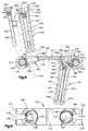
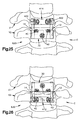
- Fig. 23-26 illustrate several embodiments which include one plate secured to one vertebra by two screws and another plate secured to another vertebra by three screws.
- Fig. 23 illustrates an apparatus 600 which includes a 2-screw plate 412 which is the same as the plate 412 described in detail with reference to Figs. 12-22.
- the plate 412 is fastened to the vertebra V1 with a pair of fasteners 40.
- the fasteners 40 (Fig. 23) are the same as the fasteners which are described in detail with reference to Figs. 1-11.
- the fasteners 40 (Fig. 23) have head end portions which are expanded into engagement with the rods 12 and 14. As a result, the plate 412 is blocked from movement relative to the rods 12 and 14, when the plate is secured to the vertebra V1.
- the apparatus 600 also includes a plate 32 which is the same plate which is described in detail with reference to Figs. 1-8.
- the plate 32 is fastened to the vertebra V2 with three fasteners 40.
- the fasteners 40 are the same as the fasteners which are described in detail with reference to Figs. 1-11.
- the fasteners 40 (Fig. 23) have head end portions which are expanded into engagement with the rods 12 and 14. As a result, the plate 32 is blocked from movement relative to the rods 12 and 14, when the plate is secured to the vertebra V2.
- both plates 32 and 412 are fixed in position relative to the rods. Both vertebrae V1 and V2 are thus fixed in position relative to the rods 12 and 14. This blocks relative movement between the vertebrae V1 and V2.
- Fig. 24 illustrates an apparatus 610 in which the relative positions of the plates 412 and 32 are reversed as compared to the positions of the plates in Fig. 20.
- the apparatus 610 (Fig. 24) is, otherwise, identical to the apparatus 600 (Fig. 23). As a result, the apparatus 610 blocks relative movement between the vertebrae V1 and V2.
- Fig. 25 illustrates an apparatus 620 which includes a plate 414 which is the same as the plate 414 described in detail with reference to Figs. 12-22.
- the plate 414 is fastened to the vertebra V1 with a pair of fasteners 422.
- the fasteners 422 (Fig. 25) are the same as the fasteners 422 which are described in detail with reference to Figs. 12-22.
- the fasteners 422 have head end portions which do not engage the rods 12 and 14. As a result, the plate 414 is movable relative to the rods 12 and 14, when the plate is secured to the vertebra V1.
- the apparatus 620 also includes a plate 32 which is the same plate which is described in detail with reference to Figs. 1-8.
- the plate 32 is fastened to the vertebra V2 with three fasteners 40.
- the fasteners 40 (Figs. 25) are the same as the fasteners 40 which are described in detail with reference to Figs. 1-11.
- the fasteners 40 have head end portions which are expanded into engagement with the rods 12 and 14. As a result, the plate 30 is blocked from movement relative to the rods 12 and 14, when the plate is secured to the vertebra V2.
- the plate 414 is movable relative to the plate 32. This allows relative movement between the vertebrae V1 and V2.
- Fig. 26 illustrates an apparatus 630 which includes a plate 412 which is the same as the plate 412 described in detail with reference to Figs. 12-22.
- the plate 412 is fastened to the vertebra V2 with a pair of fasteners 40.
- the fasteners 40 (Fig. 26) are the same as the fasteners 40 which are described in detail with reference to Figs. 1-8.
- the fasteners 40 which secure the plate 412 have head end portions which are expanded into engagement with the rods 12 and 14. As a result, the plate 412 is blocked from movement relative to the rods 12 and 14, when the plate is secured to the vertebra V2.
- the apparatus 630 also includes a plate 30 which is the same plate which is described in detail with reference to Figs. 1-8.
- the plate 30 is fastened to the vertebra V1 with three fasteners 40.
- the fasteners 40 (Fig. 26) are the same as the fasteners 40 which are described in detail with reference to Figs. 1-11.
- the fasteners 40 which secure the plate 30 have head end portions which do not engage the rods 12 and 14. As a result, the plate 30 is movable relative to the rods 12 and 14, when the plate is secured to the vertebra V1. Therefore, when the apparatus 630 is installed on the spinal column C, the plate 30 is movable relative to the plate 412. This allows relative movement between the vertebrae V1 and V2.
Abstract
Description
- The present invention relates to an apparatus and method for use in retaining vertebrae of a spinal column in a desired spatial relationship. The present invention is particularly adapted for use in retaining cervical vertebrae of a human spinal column in a desired spatial relationship.
- There are various known apparatus for retaining vertebrae of a spinal column in a desired spatial relationship. Certain of such known apparatus include rods connected to and extending between vertebrae and certain of such known apparatus include plates connected to and extending between vertebrae.
- The present invention is an apparatus for retaining first and second vertebrae of a spinal column in a desired spatial relationship. The apparatus comprises a pair of longitudinal members positionable along the spinal column. A first plate is connectable to the first vertebra and interconnects the pair of longitudinal members. First fastener means is engageable with the first plate for connecting the first plate to the first vertebra. The first fastener means has a threaded end portion for engaging the first vertebra. A second plate is connectable to the second vertebra and interconnects the longitudinal members. Second fastener means is engageable with the second plate for connecting the second plate to the second vertebra. The second fastener means has a threaded end portion for engaging the second vertebra. The apparatus is implantable in the body so that, after implantation, the apparatus is entirely within the body.
- In accordance with one feature of the present invention, the first and second vertebrae are cervical vertebrae. The first plate has an inner side surface for facing an anterior surface of the first cervical vertebra. The second plate has an inner side surface for facing an anterior surface of the second cervical vertebra.
- In accordance with another feature of the present invention, the apparatus includes means for blocking movement of the first plate, which is the lower plate, relative to the longitudinal members. The second plate, which is higher on the spine than the first plate, is movable relative to the longitudinal members along longitudinal axes of the longitudinal members. Since the second plate is movable relative to the longitudinal members, the second vertebra to which the plate is connected is movable relative to the longitudinal members. Thus, bone graft located adjacent the second vertebra carries a load as the bone and bone graft grow together. In accordance with another feature of the present
- invention, the apparatus includes means for blocking movement of both the first plate and the second plate relative to the longitudinal members.
- The present invention is also a method of retaining first and second vertebrae of a spinal column in a desired spatial relationship. The method comprises the steps of providing a pair of longitudinal members; interconnecting the longitudinal members with a first plate and a second plate; positioning the first plate on the first vertebra with an inner side surface of the first plate facing an anterior surface of the first vertebra while the first plate interconnects the pair of longitudinal members; and positioning the second plate on the second vertebra with an inner side surface of the second plate facing an anterior surface of the second vertebra while the first plate interconnects the pair of longitudinal members. The method also includes the steps of connecting the first plate to the first vertebra by engaging the first plate with a first fastener and threading an end portion of the first fastener into the first vertebra, and connecting the second plate to the second vertebra by engaging the second plate with a second fastener and threading an end portion of the second fastener into the second vertebra.
- The present invention is also a method of retaining first and second vertebrae of a spinal column in a desired spatial relationship. The method comprises the steps of positioning a first plate on a first vertebra with an inner side surface of the first plate facing a surface of the first vertebra; positioning a second plate on the second vertebra with an inner side surface of the second plate facing a surface of the second vertebra; and providing a pair of longitudinal members extending between the first and second plates and extending along the spinal column. The method also includes the steps of connecting the first plate to the first vertebra by engaging the first plate with first fastener means and threading an end portion of the first fastener means into the first vertebra; connecting the second plate to the second vertebra by engaging the second plate with second fastener means and threading an end portion of the second fastener means into the second vertebra; and enabling one of the first and second plates to move along the spinal column relative to the pair of longitudinal members and relative to the other one of the first and second plates.
- The foregoing and other features of the present invention will become more apparent to one skilled in the art upon reading the following description of embodiments of the invention with reference to the accompanying drawings, wherein:
- Fig. 1 is an elevational view of an apparatus constructed in accordance with the present invention for maintaining a desired spatial relationship between cervical vertebrae of a spinal column;
- Fig. 2 is a view of the apparatus of Fig. 1, taken along the sagittal plane as indicated by line 2-2 of Fig. 1;
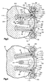
- Fig. 3 is a sectional view taken generally along line 3-3 of Fig. 2;
- Fig. 4 is a sectional view taken generally along line 4-4 of Fig. 2;
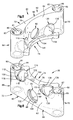
- Fig. 5 is a perspective view of a first plate which forms a portion of the apparatus of Fig. 1;
- Fig. 6 is another perspective view of the plate of Fig. 5;
- Fig. 7 is a view similar to Fig. 5 of a second plate which forms a portion of the apparatus of Fig. 1;
- Fig. 8 is another perspective view of the plate of Fig. 7;
- Fig. 9 is a view similar to Fig. 1 of a second embodiment of the invention.
- Fig. 10 is a perspective view of a plate which is constructed in accordance with a third embodiment of the present invention;
- Fig. 11 is an enlarged sectional view of a portion of the plate of Fig. 10 and showing a set screw and rod associated with the plate;
- Fig. 12 is a view of a cervical portion of a spinal column with a fourth embodiment of an apparatus constructed in accordance with the present invention connected to anterior portions of the cervical vertebrae to retain a desired spatial relationship between the cervical vertebrae;
- Fig. 13 is a sectional view, taken generally along the line 13-13 of Fig. 12;
- Fig. 14 is an enlarged exploded view of parts of Fig. 12;
- Fig. 15 is a plan view of a part shown in Fig. 14;
- Fig. 16 is a sectional view, taken generally along the line 16-16 of Fig. 12;
- Fig. 17 is an enlarged exploded view of parts of Fig. 16;
- Fig. 18 is a plan view of a part shown in Fig. 17;
- Fig. 19 is an enlarged view of parts of Fig. 17;
- Fig. 20 is an enlarged view, generally similar to Fig. 19, showing another position of the parts of Fig. 17;
- Fig. 21 is an enlarged view, generally similar to Fig. 19, showing yet another position of the parts of Fig. 17;
- Fig. 22, which is on the drawing sheet with Fig. 16, is a view of a cervical portion of a spinal column with a fifth embodiment of an apparatus constructed in accordance with the present invention connected to anterior portions of the cervical vertebrae to retain a desired spatial relationship between the cervical vertebrae;
- Fig. 23 is a view similar to Fig. 1 of an apparatus which is constructed in accordance with a sixth embodiment of the present invention;
- Fig. 24 is a view similar to Fig. 1 of an apparatus which is constructed in accordance with a seventh embodiment of the present invention;
- Fig. 25 is a view similar to Fig. 1 of an apparatus which is constructed in accordance with an eighth embodiment of the present invention; and
- Fig. 26 is a view similar to Fig. 1 of an apparatus which is constructed in accordance with a ninth embodiment of the present invention.
- The present invention relates to an apparatus and method for retaining vertebrae of a spinal column in a desired spatial relationship. The apparatus includes a pair of longitudinal members in the form of rods which are positionable along the spinal column. The apparatus also includes at least a pair of members in the form of plates for interconnecting the rods. Each plate is secured to a respective vertebra by either two or three screws. One of the plates may be a dynamic plate--that is, a plate which is movable relative to the rods when the plate is connected with its associated vertebra. An apparatus which includes a dynamic plate can allow relative movement between vertebrae which are connected by the apparatus.
- The present invention is illustrated in association with cervical vertebrae of a human spinal column. It should be understood that vertebrae other than cervical vertebrae of a human spinal column may be retained with the apparatus and method of the present invention.
- As representative of the present invention, Figs. 1-11 illustrate apparatus which includes rods interconnected by a pair of plates each secured to a respective vertebra by three screws. Specifically, Fig. 1 illustrates an
apparatus 10 for use in retaining bone portions such as cervical vertebrae V1 and V2 of a human spinal column C in a desired stabilized spatial relationship. The spinal column C has an axis A which is a vertical axis of the human body. - The
apparatus 10 includes a pair of surgicallyimplantable rods 12 and 14 (Figs. 1 and 2). Theapparatus 10 also includes first and second members orplates rods fasteners fasteners - The first rod 12 (Fig. 1) is made of a suitable biocompatible material, such as titanium or stainless steel. The
first rod 12 has an elongate cylindrical configuration and has a circular cross section taken in a plane extending perpendicular to the longitudinal central axis of the first rod. Thefirst rod 12 has a smooth outer surface. A first end portion of thefirst rod 12 is formed as acap 50. Thefirst rod 12 also has asecond end portion 52 opposite from thefirst end portion 50. Therod 12 has a uniform diameter of about three (3) millimeters throughout its extent except at thecap 50. - The
second rod 14 is identical to thefirst rod 12. Thesecond rod 14 has a first end portion which is formed as acap 54. Thesecond rod 14 also has asecond end portion 56 opposite from thefirst end portion 54. Therods rods - The
rods rods apparatus 10. If more than two vertebrae are to be held in a desired spatial relationship relative to each other by theapparatus 10, therods plates - The first plate 30 (Figs. 5 and 6) is made of a suitable biocompatible material, such as titanium or stainless steel. The
first plate 30 includes amain body portion 60. Themain body portion 60 of thefirst plate 30 has a planarouter side surface 62 for facing anteriorly or away from the first vertebra V1. Thefirst plate 30 has an arcuateinner side surface 64 for facing posteriorly or toward the first vertebra V1. Theinner side surface 64 of thefirst plate 30 may engage the anterior surface of the first vertebra V1 when the first plate is connected with the first vertebra as described below. - The
main body portion 60 of thefirst plate 30 has acentral portion 66 which extends laterally between afirst side portion 68 and asecond side portion 70 of the first plate. Because theinner side surface 64 of thefirst plate 30 has an arcuate configuration, thecentral portion 66 of the first plate is relatively thin (as viewed in a direction from left to right in Fig. 3) as compared to thefirst side portion 68 and to thesecond side portion 70. - The
main body portion 60 of thefirst plate 30 also has first andsecond end portions first end portion 72 of thefirst plate 30 includes a planarfirst end surface 76 of thefirst plate 30. Thesecond end portion 74 includes a planarsecond end surface 78 of thefirst plate 30. Thesecond end surface 78 extends parallel to thefirst end surface 76. - A
first rod passage 80 is formed in thefirst side portion 68 of thefirst plate 30. Thefirst rod passage 80 is an opening which extends between the first and second end surfaces 76 and 78 of thefirst plate 30 in a direction parallel to the planarouter side surface 62 of the first plate. Thefirst rod passage 80 is defined by acylindrical surface 81 and tapered pilot surfaces 83 and 84 at opposite ends of thecylindrical surface 81. The diameter of thecylindrical surface 81 is slightly greater than the diameter of thefirst rod 12, so that the first rod and thefirst plate 30 can be relatively movable. - The
second side portion 70 of thefirst plate 30 is a mirror image of thefirst side portion 68. Asecond rod passage 82 is formed in thesecond side portion 70 of thefirst plate 30. Thesecond rod passage 82 is an opening which extends between the first and second end surfaces 76 and 78 of thefirst plate 30 in a direction parallel to the planarouter side surface 62 of the first plate. Thesecond rod passage 82 extends parallel to thefirst rod passage 80. Thesecond rod passage 82 is defined by acylindrical surface 85 and tapered pilot surfaces 86 and 87 at opposite ends of thecylindrical surface 85. The diameter of thesecond rod passage 82 is the same as the diameter of thefirst rod passage 80. The diameter of thecylindrical surface 85 is slightly greater than the diameter of thesecond rod 14, so that the second rod and thefirst plate 30 can be relatively movable. - A circular
first fastener opening 90 extends through thecentral portion 66 of thefirst plate 30. Thefirst fastener opening 90 has an axis 92 (Fig. 2) which extends perpendicular to the plane of theouter side surface 62 of thefirst plate 30. Theaxis 92 extends in a first direction as indicated by thearrow 94, that is, from right to left as viewed in Fig. 2, when thefirst plate 30 is mounted on the first vertebra V1. Thefirst direction 94 extends perpendicular to the axes of therods - The
first fastener opening 90 is partially defined by a larger diameter cylindrical surface 96 (Fig. 6) which extends from theouter side surface 62 of thefirst plate 30 in a direction into the material of thecentral portion 66 of the first plate. The cylindrical surface 96 is centered on theaxis 92 of thefirst fastener opening 90. Thefirst fastener opening 90 is partially defined by a smaller diametercylindrical surface 98 which extends from theinner side surface 64 of thefirst plate 30 in a direction into the material of thecentral portion 66 of the first plate to a location spaced radially inward from the surface 96. Thecylindrical surface 98 is centered on theaxis 92 of thefirst fastener opening 90. - An annular shoulder surface 100 (Figs. 2 and 6) extends radially (relative to the axis 92) between the
cylindrical surfaces 96 and 98. Theshoulder surface 100 and the larger diameter cylindrical surface 96 define arecess 102 in theouter side surface 62 of thefirst plate 30. - The
main body portion 60 of thefirst plate 30 also includes a circular second fastener opening 110 formed at a location adjacent to, but spaced apart from, thefirst rod passage 80 in thefirst side portion 68 of the first plate. The second fastener opening 110 extends through both thesecond end surface 78 of thefirst plate 30 and theouter side surface 62 of the first plate. - The second fastener opening 110 is partially defined by a larger diameter cylindrical surface 112 (Fig. 6) which extends from the outer side surface of the
first plate 30 in a direction into the material of thefirst side portion 68 of the first plate. Thecylindrical surface 112 is centered on an axis 114 (Fig. 2) of thesecond fastener opening 110. Thecylindrical surface 112 is spaced apart from thefirst rod passage 80. - The second fastener opening 110 is partially defined by a smaller diameter cylindrical surface 116 (Fig. 6) which extends from the
inner side surface 64 of thefirst plate 30 in a direction into the material of thefirst side portion 68 of the first plate, to a location spaced radially inward from thesurface 112. Thecylindrical surface 116 is centered on theaxis 114 of thesecond fastener opening 110. - An annular shoulder surface 118 (Figs. 3 and 6) extends radially (relative to the axis 114) between the
cylindrical surfaces shoulder surface 118 and the larger diametercylindrical surface 112 define arecess 120 in theouter side surface 62 of thefirst plate 30. - The
axis 114 of the second fastener opening 110 extends transverse to theaxis 92 of thefirst fastener opening 90. Specifically, the axis 114 (Fig. 3) of the second fastener opening 110 converges with theaxis 92 of thefirst fastener opening 90 as viewed in a transverse plane at right angles to the vertical axis A, as can be seen from Fig. 3. In the illustrated embodiment, theaxis 114 converges at an angle of about 10° with theaxis 92 as viewed in this transverse plane. - The
axis 114 of the second fastener opening 110 also converges with theaxis 92 of thefirst fastener opening 90 as viewed in the sagittal plane, as can be seen in Fig. 2. In the illustrated embodiment, theaxis 114 converges at an angle of 45° with theaxis 92 as viewed in the sagittal plane. It is contemplated that the angle of convergence as viewed in the sagittal plane is preferably in the range of from about 30° to about 60°. - The
main body portion 60 of thefirst plate 30 also includes a circularthird fastener opening 130 formed at a location adjacent to, but spaced apart from, thesecond rod passage 82 in thesecond side portion 70 of the first plate. Thethird fastener opening 130 extends through both thesecond end surface 78 of thefirst plate 30 and theouter side surface 62 of the first plate. - The
third fastener opening 130 is partially defined by a larger diameter cylindrical surface 132 (Fig. 6) which extends from theouter side surface 62 of thefirst plate 30 in a direction into the material of thesecond side portion 70 of the first plate. Thecylindrical surface 132 is centered on an axis 134 (Fig. 4) of thethird fastener opening 130. Thecylindrical surface 132 is spaced apart from thesecond rod passage 82. - The
third fastener opening 130 is partially defined by a smaller diameter cylindrical surface 136 (Fig. 6) which extends from theinner side surface 64 of thefirst plate 30 in a direction into the material of thesecond side portion 70 of the first plate, to a location spaced radially inward from thesurface 32. Thecylindrical surface 136 is centered on theaxis 134 of thethird fastener opening 130. - An annular shoulder surface 138 (Figs. 3 and 6) extends radially (relative to the axis 134) between the
cylindrical surfaces shoulder surface 138 and the larger diametercylindrical surface 132 define arecess 140 in theouter side surface 62 of thefirst plate 30. - The axis 134 (Fig. 3) of the
third fastener opening 130 is coplanar with and extends parallel to theaxis 114 of thesecond fastener opening 110. Theaxis 134 of thethird fastener opening 130 extends transverse to theaxis 92 of thefirst fastener opening 90. Specifically, theaxis 134 of thethird fastener opening 130 converges with theaxis 92 of thefirst fastener opening 90 as viewed in a transverse plane at right angles to the vertical axis A, as can be seen from Fig. 3. In the illustrated embodiment, theaxis 134 converges with theaxis 92 at an angle of 10° as viewed in this transverse plane. - The
axis 134 of thethird fastener opening 130 also converges with theaxis 92 of thefirst fastener opening 90 as viewed in the sagittal plane, as can be seen from Fig. 2. In the illustrated embodiment, theaxis 134 converges with theaxis 92 at an angle of 45° as viewed in the sagittal plane. It is contemplated that this angle of convergence as viewed in the sagittal plane could be in the range of from about 30° to about 60°. - The
first plate 30 includes a lip portion orlip 150 which is formed as one piece with themain body portion 60 of the first plate. Thelip 150, best seen in Figs. 2 and 5, projects from thesecond end portion 74 of themain body portion 60 of thefirst plate 30. Thelip 150 projects in the first direction 94 (Fig. 2) when thefirst plate 30 is mounted on the first vertebra V1. - The
lip 150 has a planar configuration as viewed in thefirst direction 94, for example, as seen in Fig. 2. Thelip 150 has an arcuate configuration, as can be seen in Fig. 5, when viewed in a direction parallel to the plane of theouter side surface 62 of thefirst plate 30. The arcuate configuration of thelip 150 generally follows the arcuate configuration of theinner side surface 64 of themain body portion 60 of thefirst plate 30. Thelip 150 extends continuously between the first andsecond side portions first plate 30. Alternatively, thelip 150 may be discontinuous at one or more locations along the width of theplate 30. - The
lip 150 has an outer end surface 152 (Fig. 2) which is formed as an extension of thesecond end surface 78 of themain body portion 60 of thefirst plate 30. An opposite inner end surface 154 (Figs. 2 and 5) of thelip 150 extends parallel to theouter end surface 152. Thelip 150 also has aninner side surface 156 which extends between the inner and outer end surfaces 154 and 152 of thelip 150. - The second and
third fastener openings lip 150. Thesecond fastener opening 110, as can be seen in Fig. 2, extends through the corner between, or intersection of, thelip 150 and themain body portion 60 of thefirst plate 30. Thethird fastener opening 130 also extends through the corner between, or intersection of, thelip 150 and themain body portion 60 of thefirst plate 30. - The second plate 32 (Fig. 7) is generally similar in configuration to the first plate 30 (Fig. 5). The second plate 32 (Fig. 7) is configured, however, so that the head ends of fasteners received in certain fastener openings in the second plate are engageable with the
rods second plate 32 relative to therods - The
second plate 32 includes amain body portion 160 which has a planarouter side surface 162 for facing anteriorly or away from the vertebra V2. Themain body portion 160 also has an arcuateinner side surface 164 for facing posteriorly or toward the second vertebra V2. Theinner side surface 164 of thesecond plate 32 may engage the anterior surface of the second vertebra V2 when the second plate is connected with the second vertebra as described below. - The
main body portion 160 has acentral portion 166 which extends laterally between afirst side portion 168 and asecond side portion 170 of thesecond plate 32. Because theinner side surface 164 of thesecond plate 32 has an arcuate configuration, thecentral portion 166 of thesecond plate 32 is relatively thin (as viewed in a direction from left to right in Fig. 4) as compared to thefirst side portion 168 and to thesecond side portion 170. - The
main body portion 160 of thesecond plate 32 also has first andsecond end portions first end portion 172 of thesecond plate 32 includes a planarfirst end surface 176 of the second plate. Thesecond end portion 174 of thesecond plate 32 includes a planarsecond end surface 178 of the second plate. Thesecond end surface 178 extends parallel to thefirst end surface 176. - A
first rod passage 180 is formed in thefirst side portion 168 of thesecond plate 32. Thefirst rod passage 180 is an opening which extends between the first and second end surfaces 176 and 178 in a direction parallel to the planarouter side surface 162 of thesecond plate 32. Thefirst rod passage 180 is defined by acylindrical surface 181 and tapered pilot surfaces 183 and 184 at opposite ends of thecylindrical surface 181. The diameter of thecylindrical surface 181 is slightly greater than the diameter of thefirst rod 12. - A
second rod passage 182 is formed in thesecond side portion 170 of thesecond plate 32. Thesecond rod passage 182 is an opening which extends between the first and second end surfaces 176 and 178 in a direction parallel to the planarouter side surface 162 of thesecond plate 32. Thesecond rod passage 182 extends parallel to and has the same diameter as the second rod passage asfirst rod passage 180. Thesecond rod passage 182 is defined by acylindrical surface 185 and tapered pilot surfaces 186 and 187 at opposite ends of thecylindrical surface 185. The diameter of thecylindrical surface 185 is slightly greater than the diameter of thesecond rod 14. - A circular
first fastener opening 190 extends through thecentral portion 166 of thesecond plate 32. Thefirst fastener opening 190 has an axis 192 (Figs. 2 and 4) which extends perpendicular to the plane of theouter side surface 162 of thesecond plate 32. Theaxis 192 extends in thefirst direction 94 when thesecond plate 32 is mounted on the second vertebra V2. - The
first fastener opening 190 is partially defined by a larger diameter cylindrical surface 196 (Fig. 8) which extends from theouter side surface 162 of thesecond plate 32 in a direction into the material of thecentral portion 166 of the second plate. Thecylindrical surface 196 is centered on theaxis 192 of thefirst fastener opening 190. Thefirst fastener opening 190 is partially defined by a smaller diametercylindrical surface 198 which extends from theinner side surface 164 of thesecond plate 210 in a direction into the material of thecentral portion 166 of the second plate, to a location spaced radially inward from thesurface 196. Thecylindrical surface 198 is centered on theaxis 192 of thefirst fastener opening 190. - An annular shoulder surface 200 (Figs. 2 and 8) extends radially (relative to the axis 192) between the
cylindrical surfaces shoulder surface 200 and the larger diametercylindrical surface 196 define arecess 202 in theouter side surface 162 of thesecond plate 32. - The
main body portion 160 of thesecond plate 32 also includes a circular second fastener opening 210 formed at a location adjacent to and intersecting thefirst rod passage 180 in thefirst side portion 168 of the second plate. The second fastener opening 210 extends through both thesecond end surface 178 of thesecond plate 32 and theouter side surface 162 of the second plate. - The second fastener opening 210 is partially defined by a larger diameter cylindrical surface 212 (Fig. 8) which extends from the outer side surface 262 of the
second plate 32 in a direction into the material of thefirst side portion 168 of the second plate. Thecylindrical surface 212 is centered on an axis 214 (Figs. 2 and 4) of thesecond fastener opening 210. Thecylindrical surface 212 intersects thecylindrical surface 181 which defines thefirst rod passage 180. Thus, the second fastener opening 210 overlaps a portion of thefirst rod passage 180. - The second fastener opening 210 is partially defined by a smaller diameter
cylindrical surface 216 which extends from the inner side surface 264 of thesecond plate 32 in a direction into the material of thefirst side portion 168 of the second plate, to a location spaced radially inward from thesurface 212. Thecylindrical surface 216 is centered on theaxis 214 of thesecond fastener opening 210. - An annular shoulder surface 218 (Figs. 4 and 8) extends radially (relative to the axis 214) between the
cylindrical surfaces shoulder surface 218 and the larger diametercylindrical surface 212 define arecess 220 in the outer side surface 262 of thesecond plate 32. - The
axis 214 of the second fastener opening 210 extends transverse to theaxis 192 of thefirst fastener opening 190. Specifically, theaxis 214 of the second fastener opening 210 converges with theaxis 192 of thefirst fastener opening 190 as viewed in a transverse plane at right angles to the vertical axis A, as can be seen from Fig. 4. In the illustrated embodiment, theaxis 214 converges with theaxis 192 at angle of about 10° as viewed in this transverse plane. - The
axis 214 of the second fastener opening 210 also converges with theaxis 192 of thefirst fastener opening 190 as viewed in the sagittal plane, as can be seen in Fig. 2. In the illustrated embodiment, theaxis 214 converges with theaxis 192 at an angle of 45° as viewed in the sagittal plane. It is contemplated that this angle of convergence could be in the range of from about 30° to about 60° as viewed in the sagittal plane. - The
main body portion 160 of thesecond plate 32 also includes a circularthird fastener opening 230 formed at a location adjacent to and intersecting thesecond rod passage 182 in thesecond side portion 170 of the second plate. Thethird fastener opening 230 extends through both thesecond end surface 178 of thesecond plate 32 and theouter side surface 162 of the second plate. The distance between thethird fastener opening 230 in thesecond plate 32 and the second fastener opening 210 in the second plate is slightly more than the distance between thethird fastener opening 130 in thefirst plate 30 and the second fastener opening 110 in the first plate. - The
third fastener opening 230 is partially defined by a larger diameter cylindrical surface 232 (Fig. 8) which extends from the outer side surface 262 of thesecond plate 32 in a direction into the material of thesecond side portion 170 of the second plate. Thecylindrical surface 232 is centered on an axis 234 (Fig. 4) of thethird fastener opening 230. Thecylindrical surface 232 intersects thecylindrical surface 185 which defines thesecond rod passage 182. Thus, thethird fastener opening 230 overlaps a portion of thesecond rod passage 182. - The
third fastener opening 230 is partially defined by a smaller diameter cylindrical surface 236 (Fig. 8) which extends from the inner side surface 264 of thesecond plate 32 into the material of thesecond side portion 170 of the second plate to a location spaced radially inward from thesurface 232. Thecylindrical surface 236 is centered on theaxis 234 of thethird fastener opening 230. - An annular shoulder surface 238 (Figs. 4 and 8) extends radially (relative to the axis 234) between the
cylindrical surfaces shoulder surface 238 and the larger diametercylindrical surface 232 define arecess 240 in theouter side surface 162 of thesecond plate 32. - The
axis 234 of thethird fastener opening 230 is coplanar with and extends parallel to theaxis 214 of thesecond fastener opening 210. Theaxis 234 of thethird fastener opening 230 extends transverse to theaxis 192 of thefirst fastener opening 190. Specifically, theaxis 234 of thethird fastener opening 230 converges with theaxis 192 of thefirst fastener opening 190 as viewed in a transverse plane at right angles to the vertical axis A, as can be seen from Fig. 4. In the illustrated embodiment, theaxis 234 converges with theaxis 192 at an angle of about 10° as viewed in this transverse plane. - The
axis 234 of thethird fastener opening 230 also converges with theaxis 192 of thefirst fastener opening 190 as viewed in the sagittal plane, as can be seen from Fig. 2. In the illustrated embodiment, theaxis 234 converges with theaxis 192 at an angle of 45°. It is contemplated that this angle of convergence as viewed in the sagittal plane could be in the range of from about 30° to about 60°. - The
second plate 32 includes a lip portion orlip 250 which is formed as one piece with themain body portion 160 of the second plate. Thelip 250, best seen in Figs. 4 and 7, projects from thesecond end portion 174 of themain body portion 160 of thesecond plate 32. Thelip 250 projects in the first direction 94 (Fig. 2) when thesecond plate 32 is mounted on the second vertebra V2. - The
lip 250 has a planar configuration as viewed in thefirst direction 94, for example, as seen in Fig. 2. Thelip 250, as viewed in a direction parallel to the plane of theouter side surface 162 of thesecond plate 32, has an arcuate configuration generally following the arcuate configuration of theinner side surface 164 of themain body portion 160 of thesecond plate 32. Thelip 250 extends continuously between the first andsecond side portions second plate 32. Alternatively, thelip 250 may be discontinuous at one or more locations along the width of thesecond plate 32. - The
lip 250 has an outer end surface 252 (Fig. 2) which is formed as an extension of thesecond end surface 178 of themain body portion 160 of thesecond plate 32. An opposite inner end surface 254 (Figs. 2 and 8) of thelip 250 extends parallel to theouter side surface 252. Thelip 250 also has aninner side surface 256 which extends between the inner and outer end surfaces 252 and 254 of thelip 250. The second andthird fastener openings lip 250. Thesecond fastener opening 210, as well as thethird fastener opening 230, extend through the corner between, or intersection of, thelip 250 and themain body portion 160 of thesecond plate 32. - The
fasteners first plate 30 with the first vertebra V1 and thesecond plate 32 with the second vertebra V2, are identical to each other. Because the fasteners 38-48 are identical, only thefastener 40 is described herein in detail. - The fastener 40 (Fig. 3) includes a
sleeve 300 and anexpander 310. Thesleeve 300 has a hollow,elongate shank portion 302 centered on a longitudinalcentral axis 304 of thefastener 40. Theshank portion 302 defines a cylindricalcentral opening 308 in thesleeve 300. A coarse externalhelical thread convolution 306 is formed on the outer peripheral surface of theshank portion 302 of thesleeve 300. - The
shank portion 302 of thesleeve 300 is radially and axially slotted so that the shank portion is expandable radially. A series of projections (not shown) are formed on the inner surface of thesleeve 300 for engagement by theexpander 310 to expand theshank portion 302 of the sleeve in a manner described below. - A
head end portion 314 of thesleeve 300 has a cylindricalouter side surface 316. An annular lip orrim 318 extends around thehead end portion 314 of thesleeve 300 and projects radially outward from theouter side surface 316. Thehead end portion 314 of thesleeve 300 has a conicalinner side surface 320 and a conicalinner side surface 322. The conicalinner side surface 322 merges with aninternal thread convolution 324 formed on thesleeve 300. - The
head end portion 314 of thesleeve 300 is radially and axially slotted to define foursegments 326 of the head end portion. The foursegments 326 are movable radially relative to each other and to theaxis 304 of thefastener 40 so that thehead end portion 314 of thesleeve 300 is expandable radially. - The
expander 310 has a head end portion 340 and ashank portion 342. Aninner end 344 of theshank portion 342 of theexpander 310 is slightly larger in diameter than the cylindricalcentral opening 308 in thesleeve 300. - The head end portion 340 of the
expander 310 has anX-shaped driver slot 346 for receiving a driving tool for rotating the expander relative to thesleeve 300. The head end portion 340 has a conicalouter side surface 348 and a conicalouter side surface 350. The conicalouter side surface 350 on the head end portion 340 of theexpander 310 has a different angle of taper than does the conicalinner side surface 322 on thehead end portion 314 of thesleeve 300. - The conical
outer side surface 350 on the head end portion 340 of theexpander 310 merges with anexternal thread convolution 352 formed on theexpander 310. Theexternal thread convolution 352 on theexpander 310 screws into theinternal thread convolution 324 on thesleeve 300. - To install (implant) the
apparatus 10 on the spinal column C, therods plates first rod 12 is inserted through thefirst rod passage 80 in thefirst plate 30 and through thefirst rod passage 180 in thesecond plate 32. One of the tapered pilot surfaces 83 and 84 on thefirst plate 30, and one of the tapered pilot surfaces 183 and 184 on thesecond plate 32, guide insertion of thefirst rod 12. Thesecond rod 12 is inserted through thesecond rod passage 82 in thefirst plate 30 and through thesecond rod passage 182 in thesecond plate 32. One of the tapered pilot surfaces 86 and 87 on thefirst plate 30, and one of the tapered pilot surfaces 186 and 187 on thesecond plate 32, guide insertion of thesecond rod 14. - The assembly of the
rods plates first end surface 154 on thelip 150 of the first plate engages alower surface 360 on the first vertebra V1. Thelower surface 360 on the first vertebra V1 faces toward the second vertebra V2. Thesecond plate 32 is positioned adjacent to the second vertebra V2 so that thefirst end surface 254 on thelip 250 of the second plate engages anupper surface 362 on the second vertebra V2. Theupper surface 362 on the second vertebra V2 faces toward the first vertebra V1. - With the
first plate 30 on the first vertebra V1, and thesecond plate 32 on the second vertebra V2, a suitable drill guide and drill (not shown) are used to drill fastener openings in the first vertebra V1 and in the second vertebra V2. - The
fasteners first plate 30 with the first vertebra. The insertion and securing of thefastener 40, although not necessarily performed first, will be described as exemplary. - The
sleeve 300 of thefastener 40 is inserted through the second fastener opening 110 in thefirst plate 30. Thesleeve 300 of thefastener 40 is threaded into the drilled opening in the vertebra V1 in a known manner (not shown) to fix the sleeve in position in the vertebra V1. Theunexpanded head portion 314 of thesleeve 300 is disposed in therecess 120 in thefirst plate 30. - The
expander 310 of thefastener 40 is then inserted into thesleeve 300. The externally threadedportion 352 of theexpander 310 is screwed into theinternal threads 324 on thesleeve 300. When theexpander 310 is fully screwed into thesleeve 300, theinner end portion 344 of theexpander 310 causes theshank portion 302 of the sleeve to expand radially outward, helping to lock the sleeve in place in the vertebra V1. When theexpander 310 is fully screwed into thesleeve 300, the head portion 340 of theexpander 310 engages thehead portion 314 of thesleeve 300. The head portion 340 of theexpander 310 wedges the lockingsegments 326 on thesleeve 300 radially outward into engagement with thefirst plate 30 to rigidly lock thefastener 40 in position relative to the first plate. The head of thefastener 40 is adjacent to thelip 150. - The remaining
fasteners first plate 30 are similarly secured to the vertebra V1 and are rigidly locked to the first plate. The heads of thefasteners lip 150. As a result, thefirst plate 30 is securely connected with the first vertebra V1. - The
fasteners second plate 32. The heads of thefasteners lip 250. As a result, thefasteners second plate 32 and thesecond plate 32 is securely connected with the second vertebra V2. - As can be seen in Fig. 2, the fastener 40 (as well as the
fastener 42, not shown in Fig. 2) extends at an angle (upward as viewed in Fig. 2) to thelip 150. Accordingly, when thefasteners lip 150 of thefirst plate 30 tightly against thesurface 360 of the vertebra, that is, in an upward direction as viewed in Fig. 2. At the same time, thefasteners fastener 38, tend to draw themain body portion 60 of thefirst plate 30 tightly against the anterior surface of the first vertebra V1, that is, in a direction to the left as viewed in Fig. 2. Accordingly, it can be seen that tightening thefasteners first plate 30 in two directions against the first vertebra V1. - The
first fastener 38 has a longitudinal central axis which is coincident with theaxis 92 of thefirst fastener opening 90 when thefirst fastener 38 is disposed in thefirst fastener opening 90 in thefirst plate 30. When thesecond fastener 40 is disposed in the second fastener opening 110 in thefirst plate 30, the longitudinalcentral axis 304 of thesecond fastener 40 is coincident with theaxis 114 of thesecond fastener opening 110. - As described above, the
axis 92 of thefirst fastener opening 90 and theaxis 114 of the second fastener opening 110 converge at an acute angle as viewed in the sagittal plane (Fig. 2). Therefore, the longitudinal axis of thefirst fastener 38 and thelongitudinal axis 304 of thesecond fastener 40 converge at an acute angle as viewed in the sagittal plane (Fig. 2) when the first andsecond fasteners first plate 30 with the first vertebra V1. In the illustrated embodiment, the axis of thefirst fastener 38 and theaxis 304 of thesecond fastener 40 converge at an angle of about 45° as viewed in the sagittal plane. It is contemplated that this angle of convergence in the sagittal plane is preferably in the range of from about 30° to about 60°. - When the
third fastener 42 is disposed in thethird fastener opening 130 in thefirst plate 30, the longitudinal central axis of thethird fastener 42 is coincident with theaxis 134 of thethird fastener opening 130. As described above, theaxis 92 of thefirst fastener opening 90 and theaxis 134 of thethird fastener opening 110 converge at an acute angle as viewed in the sagittal plane (Fig. 2). Therefore, the longitudinal axis of thefirst fastener 38 and the longitudinal axis of thethird fastener 42 converge at an acute angle as viewed in the sagittal plane (Fig. 2) when the first andthird fasteners first plate 30 with the first vertebra V1. In the illustrated embodiment, the axis of thefirst fastener 38 and the axis of thethird fastener 42 converge at an angle of about 45° as viewed in the sagittal plane. It is contemplated that this angle of convergence in the sagittal plane is preferably in the range of from about 30° to about 60°. - The
second plate 32 is, in a similar manner, secured in position relative to the second vertebra V2. Tightening thefasteners second plate 32 in two directions against the second vertebra V2. - When the
first fastener 44, thesecond fastener 46, and thethird fastener 48 connect thesecond plate 32 with the second vertebra V2, the axis of thefirst fastener 44 and the axis of thesecond fastener 46 converge at an acute angle as viewed in the sagittal plane (Fig. 2). Also, the axis of thefirst fastener 44 and the axis of thethird fastener 48 converge at an acute angle as viewed in the sagittal plane (Fig. 2). In the illustrated embodiment, these axes converge at an angle of about 45° as viewed in the sagittal plane. It is contemplated that this angle of convergence in the sagittal plane could be in the range of from about 30° to about 60°. - The fact that there are three screws which secure each one of the
plates apparatus 10 maintain the vertebrae V1 and V2 in place when the cervical spine is subjected to various degrees of motion of the human head. - When the
second plate 32 is being connected with the second vertebra V2, theouter fasteners fasteners second plate 32 with therods segments 326 on thesleeves 300 of thefasteners 46 and 48 (Fig. 4) move radially outward into engagement with therods fasteners rods fasteners segments 326 of the fasteners also causes the rods to be clamped against thecylindrical surfaces rod passages second plate 32. As a result, the expandedfasteners rods - The
first plate 30, in contrast, is movable relative to therods third fastener openings rod passages first plate 30 is movable relative to thesecond plate 32. - Accordingly, the first vertebra V1 is movable vertically downward relative to the second vertebra V2. This relative movement allows for the maintaining of a load on bone graft placed between the vertebrae V1 and V2. If the
first plate 30 were not movable vertically downward relative to thesecond plate 32, then the distance between the vertebrae V1 and V2 would be fixed. If bone graft were placed between the vertebrae V1 and V2 and the bone graft resorbed sufficiently, the bone graft could possibly shrink out of engagement with one or both of the vertebrae V1 and V2. Allowing relative movement of theplates lips plates - The
caps rods - It may not be necessary or desirable, in some circumstances, to use a dynamic (movable) plate such as the
plate 30. In such circumstances, two locking plates identical to theplate 32 can be used in thesame apparatus 10. Such a system is illustrated in Fig. 9. The upper plate 32 (Fig. 9) is fixed in position relative to the vertebra V1 and to therods rods - Since the
rods plates rods rods apparatus 10. This minimizes the chance of contact between theapparatus 10 and parts of the body such as the esophagus. Also, since the fasteners are located between the rods, the fasteners are more easily installed than if the fasteners were otherwise located, for example, if the rods were located between the fasteners. - Figs. 10 and 11 illustrate a
plate 30a which is constructed in accordance with another embodiment of the present invention. Theplate 30a can be substituted, in theapparatus 10, for theplate 30. Theplate 30a is generally similar to the plate 30 (Figs. 5 and 6), and similar reference numerals are used to designate similar parts, with the suffix "a" added in Figs. 10 and 11 for clarity. - In the
plate 30a, a pair ofset screws 370 are provided for engaging therods outer side surface 62a of theplate 30a is recessed at 372 adjacent to thesecond rod passage 82a. Aseat 374 extends inwardly from therecess 372 to a threadedopening 376. Aninner end portion 378 of theopening 376 intersects with thesecond rod passage 82a. On theopposite side portion 68a of theplate 30a, a second threadedopening 380 intersects thefirst rod passage 80a. - After the
plate 30a is assembled with therods fastener openings plate 30a, to secure the plate to its associated bone portion. The head end portions of the fasteners for theplate 30a do not engage therods plate 30a. - A
set screw 370 is threaded into theopening 376. Aninner end portion 382 of theset screw 370 engages the cylindrical outer surface of thesecond rod 14. The engagement of theset screw 370 with thesecond rod 14 clamps the rod against thesecond side portion 70a of theplate 30a. Anotherset screw 370 is threaded into theopening 380 to engage thefirst rod 12 and clamp the first rod against thefirst side portion 68a of theplate 30a. - As a result, the
set screws 370, therods plate 30a are interlocked. Theplate 30a is not movable relative to (along the length of) therods plate 30a is fixed to its associated bone portion, then the bone portion also is not movable relative to therods - In the
plate 30a, a portion of thelip 150a is removed at the location of thefastener openings lip segments side portions plate 30a. A portion of thelip 150a also is removed at the lateral center of theplate 30a, and anotch 384 is provided in theplate 30a, again to increase visibility. Thelip segments plate 30a. - Figs. 12-22 illustrate apparatus which include rods interconnected by a pair of plates each secured to a respective vertebra by two screws. Specifically, Fig. 12 illustrates an apparatus which includes a pair of surgically
implantable rods 410 for stabilizing a human spinal column C. Therods 410 are connected to anterior portions of cervical vertebrae V of the spinal column by plates ormembers rod 410 is elongate and has a circular cross section taken in a plane extending perpendicular to the longitudinal central axis of the rod. Therods 410 are bendable in any desired plane to conform to a desired curvature of the spinal column C. Therods 410 have sufficient strength and rigidity to maintain the vertebrae V in the desired relationship. Therods 410 are made of a biocompatible material such as titanium or stainless steel. - Each of the
rods 410 has a length which is at least sufficient to enable the rod to span at least two of the cervical vertebrae V. In the embodiment of the invention illustrated in Fig. 12, therods 410 span two vertebrae V. Of course, the length of therods 410 will depend upon the condition to be corrected and the number of vertebrae V to be held in a desired spatial relationship relative to each other by therods 410. - The
plate 412 is connected to a vertebra V by fasteners 420 (Fig. 13). Thefasteners 420 also fix or lock therods 410 relative to theplate 412 to prevent relative movement between therods 410 and the plate. Theplate 414 is connected to a vertebra V by fasteners 422 (Fig. 16). Thefasteners 422 permit relative movement between theplate 414 and therods 410. Therefore, theplate 414 is considered a dynamic plate. - Each
rod 410 terminates in acap 424 engageable with theplate 414. Thecaps 424 prevent movement of theplate 414 relative to therods 410 in a direction away from theplate 412, while allowing movement of theplate 414 in a direction toward theplate 412. - Each of the fasteners 420 (Figs. 13 and 14) includes a
sleeve 430 and anexpander 432 located within the sleeve. Thesleeve 430 has an axially extendingcentral opening 434 for receiving theexpander 432. Thesleeve 430 includes a coarse externalhelical thread convolution 436 for engaging a vertebra V. - The sleeve 430 (Fig. 14) has a
head end portion 438 with a cylindricalouter side surface 440. An annular lip orrim 442 extends around thehead end portion 438 of thesleeve 430 and projects radially outward from the cylindricalouter side surface 440. Thehead end portion 438 of thesleeve 430 is radially and axially slotted to define four segments 444 (Fig. 12) of thehead end portion 438. The foursegments 444 are movable radially outward relative to each other. Thus, thehead end portion 438 is expandable. The radially and axially extending slots in thehead end portion 438 receive a driving tool for threading thesleeve 430 into a vertebra. An end portion 448 (Fig. 14) of thesleeve 430 opposite from thehead end portion 438 is radially and axially slotted to permit radially outward expansion of theend portion 448. - The
opening 434 of thesleeve 430 has a first diameter located along acentral portion 450 of thesleeve 430 and a second diameter smaller than the first diameter located adjacent theend portion 448. Thesleeve 430 has an internally threadedportion 452 between thecentral portion 450 and thehead end portion 438. Thehead end portion 438 has a conical-shapedsurface 454 that tapers from a larger diameter to a smaller diameter adjacent another conical-shapedsurface 456. Thesurface 456 interconnects thesurface 454 and the threadedportion 452. Thesurface 456 tapers from the larger diameter adjacent thesurface 454 to the smaller diameter of the threadedportion 452. - The
expander 432 has a rod-shapedportion 460 for extending in theopening 434. Therod portion 460 has a diameter which is approximately equal to the diameter of theopening 434 in thecentral portion 450 of the sleeve. Therod portion 460 engages the interior of theend portion 448 of thesleeve 430 and causes theend portion 448 to expand and help retain thefastener 420 in the vertebra V. - The
expander 432 has ahead end portion 462 with an X-shaped driver slot for receiving a driving tool for rotating the expander relative to thesleeve 430. Thehead end portion 462 has a taperingsurface 464 for engaging the taperingsurface 454 of thesleeve 430. Theexpander 432 includes a threadedportion 466 for threadably engaging the threadedportion 452 of thesleeve 430. The taperingsurface 464 of theexpander 432 engages the taperingsurface 454 of thesleeve 430 to move the foursegments 444 radially outward. Therefore, thehead end portion 438 of thesleeve 430 expands. - The member or plate 412 (Figs. 13-15) is made of a suitable biocompatible material, such as titanium or stainless steel. The
plate 412 includes asurface 470 for engaging an anterior surface of the vertebra V and asurface 472 opposite from thesurface 470 for facing away from the vertebra V. Theplate 412 has generallyparallel openings 474 for receiving therods 410. Slots 475 (Fig. 15) extend fromside surfaces 476 of theplate 412 and intersect theopenings 474. Theslots 475 define a pair of axially spaced arcuate surfaces that engage portions of therod 410 at axially spaced locations. - The plate 412 (Figs. 14 and 15) has a pair of
openings 478 for receiving thefasteners 420 located adjacent the side surfaces 470 and intersecting theopenings 474. Theopenings 478 haveaxes 479 that extend at an angle relative to each other. Each of thefastener openings 478 is partially defined by a larger diametercylindrical surface 480 which extends parallel to theaxis 479 of the fastener opening. Thefastener opening 478 is partially defined by a smaller diametercylindrical surface 482 which extends parallel to theaxis 479 of the opening. Anannular shoulder surface 484 extends radially between thesurfaces shoulder surface 484 defines a seat or recess in theopening 478 against which therim 442 of thesleeve 430 engages. Theaxes 479 of theopenings 478 extend at an angle relative to each other so that thefasteners 420 extend at an angle to each other. - When the
plate 412 is to be connected to the anterior portion of the cervical vertebra V, it is positioned on the anterior portion of the cervical vertebra with thesurface 470 facing the anterior portion of the vertebra V and therods 410 extending through theopenings 474. Thesleeves 430 of thefasteners 420 are placed through theopenings 478 in theplate 412 and threaded into the vertebra V. Thesleeves 430 are threaded into the vertebra V until therim 442 of the sleeve engages theshoulder surface 484 and presses thesurface 470 of theplate 412 against the vertebra V. Theexpanders 432 are threaded into thesleeves 430 to cause thehead end portions 438 to expand so that thesegments 444 expand radially outward into engagement with thecylindrical surfaces 480 of theopenings 478. Thehead end portion 438 also expands into engagement with therod 410 and clamps the rod in theopening 474. Accordingly, thefasteners 420, theplate 412, and therods 410 are prevented from moving relative to each other. - When the apparatus is positioned on the spinal column C, the
fasteners 420 secure theplate 412 to the vertebra V. Theplate 412 is also fixed in position relative to therods 410, as described above. Accordingly, the vertebra connected to theplate 412 is fixed in position relative to therods 410. - Each of the fasteners 422 (Figs. 16 and 17) which secure the
plate 414 to a vertebra V includes asleeve 490 and anexpander 492 located within the sleeve. Eachfastener 422 has a longitudinalcentral axis 493. Thesleeve 490 has an axially extendingcentral opening 494 for receiving theexpander 492. Thesleeve 490 includes a coarse externalhelical thread convolution 496 for engaging a vertebra V. - The sleeve 490 (Fig. 17) has a
head end portion 498 with a part sphericalouter side surface 500. Thehead end portion 498 of thesleeve 490 is radially and axially slotted to define four segments 504 (Fig. 12) of thehead end portion 498. The foursegments 504 are movable radially inward and outward relative to each other so that thehead end portion 498 is expandable and collapsible. The radially and axially extending slots in thehead end portion 498 receive a driving tool for threading thesleeve 490 into a vertebra V. An end portion 508 (Fig. 17) of thesleeve 490 opposite from thehead end portion 498 is radially and axially slotted to permit radially outward expansion of theend portion 508. Thehead end portion 498 of thefastener 422 has asurface 548 facing away from theend portion 508. - The
opening 494 of thesleeve 490 has a first diameter located along acentral portion 510 of thesleeve 490 and a second diameter smaller than the first diameter located adjacent theend portion 508. Thesleeve 490 has an internally threadedportion 512 between thecentral portion 450 and thehead end portion 498. Thehead end portion 498 has a conical-shapedsurface 514 that tapers from a larger diameter to a smaller diameter adjacent another conical-shapedsurface 516. Thesurface 516 interconnects thesurface 514 and the threadedportion 512. Thesurface 516 tapers from the larger diameter adjacent thesurface 514 to the smaller diameter of the threadedportion 512. - The
expander 492 has a rod-shapedportion 520 for extending into theopening 494. Therod portion 520 has a diameter which is approximately equal to the diameter of theopening 494 in thecentral portion 510 of thesleeve 490. Therod portion 520 engages the interior of theend portion 508 of thesleeve 490 and causes theend portion 508 to expand and help retain thefastener 422 in the vertebra V. - The
expander 492 has a head end portion 521 with an X-shaped driver slot for receiving a driving tool for rotating the expander relative to thesleeve 490. Thehead end portion 522 has a taperingsurface 524 for engaging the taperingsurface 514 of thesleeve 490. Theexpander 492 includes a threadedportion 526 for threadably engaging the threadedportion 512 of theexpander 490. The taperingsurface 524 of theexpander 492 engages the taperingsurface 514 of thesleeve 490 to move the foursegments 504 radially outward. Therefore, thehead end portion 498 of thesleeve 490 expands. - The member or plate 414 (Figs. 16-18) is made of a suitable biocompatible material, such as titanium or stainless steel. The
plate 414 includes asurface 530 for engaging an anterior surface of the vertebra V and asurface 532 opposite from thesurface 530 for facing away from the vertebra V. Theplate 414 has generallyparallel rod openings 534 for receiving therods 410. Theplate 414 has a pair offastener openings 538 for receiving thefasteners 422 located adjacent side surfaces 536 of theplate 414. Theopenings 538 haveaxes 539 extending at an angle to each other. - Each
fastener opening 538 is partially defined by a part spherical surface 540 (Figs. 17-21) centered on theaxis 539. The partspherical surface 540 defines a seat or recess in theopening 538 against which the partspherical surface 500 of thesleeve 490 engages. - The part
spherical recess 540 has amajor diameter 542. Afirst portion 544 of therecess 540 is located on one side of themajor diameter 542 and adjacent thesurface 532 of theplate 414. Asecond portion 546 of therecess 540 is located on the other side of themajor diameter 542 and adjacent thesurface 530 of theplate 414. - When the
plate 414 is to be connected to a vertebra V, theplate 414 is placed on the vertebra V with thesurface 530 engaging the anterior portion of the vertebra V and therods 410 extending through theopenings 534. Thesleeves 490 are threaded into the vertebra V through theopenings 538 in theplate 414. As thehead end portion 498 of thesleeve 490 enters theopening 538 in theplate 414 thesegments 504 are compressed radially inward then expand radially outward. Thesurfaces 548 on thehead end portions 498 are located in thefirst portions 544 of therecesses 540 when thehead end portions 498 are received in the recesses. Because themajor diameter 542 of eachrecess 540 is spaced inward from theouter surface 532 of theplate 414, the expandedfasteners 422 resist movement out of the recesses in the plate. - The
expander 492 is threaded into thesleeve 490 and causes thehead end portion 498 to expand into engagement with theopening 538 and prevent relative movement between theplate 414 and thefastener 422. The engagement of the partspherical surfaces 500 of thesleeves 490 with the partspherical surfaces 540 of theopenings 538, enables thefasteners 422 to have a plurality of positions in which theaxis 493 of eachfastener 422 extends at an angle to theaxis 539 of its associatedopening 538 in any direction. Preferably, theaxis 493 of eachfastener 422 can be positioned at a maximum of approximately 10° in any direction relative to theaxis 539 of its associatedopening 538. Three alternative positions are shown in Figs. 19-21. - The
fasteners 422 secure theplate 414 to the vertebra V. However, theplate 414 is movable relative to therods 410. Accordingly, the vertebra V connected to theplate 414 is movable relative to therods 410 along the longitudinal axes of the rods. - Accordingly, the vertebra V corrected to the
plate 414 is movable vertically downward toward the vertebra that theplate 412 is connected to. This relative movement allows for the maintaining of a load on bone graft placed between the vertebrae V. If theplate 414 was not movable relative to theplate 412, then the distance between the vertebrae V would be fixed. If a bone graft is placed between the vertebrae V and the bone graft resorbed sufficiently, the bone graft could possibly shrink out of engagement with one or both of the vertebrae V. Allowing relative movement of theplates - It may not be necessary, in some circumstances, to use a dynamic (movable) plate such as the
plate 414. In such circumstances, two plates identical to theplate 412 can be used in the same apparatus. Such a system is illustrated in Fig. 22. - In Fig. 22 a pair of surgically
implantable rods 560 are connected to anterior portions of cervical vertebrae V of a spinal column C by a pair of identical plates ormembers 562. Theplates 562 are identical to theplates 412 illustrated in Figs. 12-14 and will not be described in detail. Theplates 562 are connected to the vertebrae V byfasteners 564. Thefasteners 564 are identical to thefasteners 420 illustrated in Figs. 12-14 and will not be described in detail. Thefasteners 564 also fix therods 560 relative to theplates 562 to prevent relative movement between the rods and the plates. The apparatus illustrated in Fig. 22 prevents relative movement between the vertebrae V since theplates 562 androds 560 are prevented from moving relative to each other by thefasteners 564. - Fig. 23-26 illustrate several embodiments which include one plate secured to one vertebra by two screws and another plate secured to another vertebra by three screws. Specifically, Fig. 23 illustrates an
apparatus 600 which includes a 2-screw plate 412 which is the same as theplate 412 described in detail with reference to Figs. 12-22. Theplate 412 is fastened to the vertebra V1 with a pair offasteners 40. The fasteners 40 (Fig. 23) are the same as the fasteners which are described in detail with reference to Figs. 1-11. The fasteners 40 (Fig. 23) have head end portions which are expanded into engagement with therods plate 412 is blocked from movement relative to therods - The
apparatus 600 also includes aplate 32 which is the same plate which is described in detail with reference to Figs. 1-8. Theplate 32 is fastened to the vertebra V2 with threefasteners 40. Thefasteners 40 are the same as the fasteners which are described in detail with reference to Figs. 1-11. The fasteners 40 (Fig. 23) have head end portions which are expanded into engagement with therods plate 32 is blocked from movement relative to therods - Therefore, when the
apparatus 600 is installed on the spinal column C, bothplates rods - Fig. 24 illustrates an
apparatus 610 in which the relative positions of theplates apparatus 610 blocks relative movement between the vertebrae V1 and V2. - Fig. 25 illustrates an
apparatus 620 which includes aplate 414 which is the same as theplate 414 described in detail with reference to Figs. 12-22. Theplate 414 is fastened to the vertebra V1 with a pair offasteners 422. The fasteners 422 (Fig. 25) are the same as thefasteners 422 which are described in detail with reference to Figs. 12-22. Thefasteners 422 have head end portions which do not engage therods plate 414 is movable relative to therods - The
apparatus 620 also includes aplate 32 which is the same plate which is described in detail with reference to Figs. 1-8. Theplate 32 is fastened to the vertebra V2 with threefasteners 40. The fasteners 40 (Figs. 25) are the same as thefasteners 40 which are described in detail with reference to Figs. 1-11. Thefasteners 40 have head end portions which are expanded into engagement with therods plate 30 is blocked from movement relative to therods - Therefore, when the
apparatus 620 is installed on the spinal column C, theplate 414 is movable relative to theplate 32. This allows relative movement between the vertebrae V1 and V2. - Fig. 26 illustrates an
apparatus 630 which includes aplate 412 which is the same as theplate 412 described in detail with reference to Figs. 12-22. Theplate 412 is fastened to the vertebra V2 with a pair offasteners 40. The fasteners 40 (Fig. 26) are the same as thefasteners 40 which are described in detail with reference to Figs. 1-8. Thefasteners 40 which secure theplate 412 have head end portions which are expanded into engagement with therods plate 412 is blocked from movement relative to therods - The
apparatus 630 also includes aplate 30 which is the same plate which is described in detail with reference to Figs. 1-8. Theplate 30 is fastened to the vertebra V1 with threefasteners 40. The fasteners 40 (Fig. 26) are the same as thefasteners 40 which are described in detail with reference to Figs. 1-11. Thefasteners 40 which secure theplate 30 have head end portions which do not engage therods plate 30 is movable relative to therods apparatus 630 is installed on the spinal column C, theplate 30 is movable relative to theplate 412. This allows relative movement between the vertebrae V1 and V2. - From the above description of the invention, those skilled in the art will perceive improvements, changes and modifications in the invention. Such improvements, changes and modifications within the skill of the art are intended to be covered by the appended claims.
Claims (25)
- An apparatus for retaining first and second cervical vertebrae of a spinal column in a desired spatial relationship, said apparatus comprising:a pair of longitudinal members positionable along the spinal column;a first plate connectable to the anterior surface of the first cervical vertebra, said first plate interconnecting said pair of longitudinal members;first fastener means engageable with said first plate for connecting said first plate to the first cervical vertebra, said first fastener means having a threaded end portion for engaging the first cervical vertebra;a second plate connectable to the anterior surface of the second cervical vertebra, said second plate interconnecting said longitudinal members; andsecond fastener means engageable with said second plate for connecting said second plate to the second cervical vertebra, said second fastener means having a threaded end portion for engaging the second cervical vertebra.
- An apparatus as set forth in claim 1 wherein said first fastener means comprises three screws each having a respective threaded end portion for engaging the first vertebra and each having a respective second end portion for engaging said first plate.
- An apparatus as set forth in claim 2 wherein said second fastener means comprises three screws each having a respective threaded end portion for engaging the second vertebra and each having a respective second end portion for engaging said first plate.
- An apparatus as set forth in claim 1 wherein each one of said first and second plates has a pair of rod passages, said pair of longitudinal members comprising a pair of rods extendable through said rod passages in said first and second plates.
- An apparatus as set forth in claim 4 wherein each one of said rod passages in said first plate comprises an opening extending between opposite end surfaces of said first plate in a direction generally parallel to said inner side surface of said first plate and generally parallel to the other one of said rod passages in said first plate.
- An apparatus as set forth in claim 1 wherein said first fastener means comprises a first plurality of screws located between said longitudinal members and said second fastener means comprises a second plurality of screws located between said longitudinal members.
- An apparatus for retaining first and second vertebrae of a spinal column in a desired spatial relationship, said apparatus comprising:a pair of longitudinal members having longitudinal axes and positionable with their longitudinal axes extending along the spinal column;a first plate connectable to the first vertebra and for interconnecting said pair of longitudinal members;first fastener means engageable with said first plate for connecting said first plate to the first vertebra, said first fastener means having a threaded end portion for engaging the first vertebra;said first plate being blocked from movement relative to said longitudinal members;a second plate connectable to the second vertebra and for interconnecting said pair of longitudinal members, said second plate being movable relative to said longitudinal members along the longitudinal axes of said longitudinal members; andsecond fastener means engageable with said second plate for connecting said second plate to the second vertebra, said second fastener means having a threaded end portion for engaging the second vertebra.
- An apparatus as set forth in claim 7 wherein said first plate has spaced apart first and second rod passages, said first fastener means being engageable with said first plate at a location intermediate said first and second rod passages in said first plate;said second plate having spaced apart first and second rod passages, said second fastener means being engageable with said second plate at a location intermediate said first and second rod passages in said second plate;said first longitudinal member extending through said first rod passages in said first and second plates when said first and second plates interconnect said pair of longitudinal members;said second longitudinal member extending through said second rod passages in said first and second plates when said first and second plates interconnect said pair of longitudinal members.
- An apparatus as set forth in claim 8 wherein said first fastener means comprises a plurality of screws located between said longitudinal members, each screw having a respective threaded end portion for engaging the first vertebra and each having a second end portion for engaging said first plate.
- An apparatus as set forth in claim 8 wherein each one of said rod passages in said first plate comprises an opening extending between opposite end surfaces of said first plate, said rod passages in said first plate extending generally parallel to each other;each one of said rod passages in said second plate comprising an opening extending between opposite end surfaces of said second plate, said rod passages in said second plate extending generally parallel to each other.
- An apparatus as set forth in claim 7 wherein said first fastener means comprises three screws each having a respective threaded end portion for engaging the first vertebra and each having a respective second end portion for engaging said first plate, said second fastener means comprising three additional screws each having a respective threaded end portion for engaging the second vertebra and each having a respective second end portion for engaging said second plate.
- An apparatus for retaining first and second vertebrae of a spinal column in a desired spatial relationship, said apparatus comprising:a pair of longitudinal members positionable along the spinal column;a first plate connectable to the first vertebra and for interconnecting said pair of longitudinal members;first fastener means engageable with said first plate for connecting said first plate to the first vertebra, said first fastener means having a threaded end portion for engaging the first vertebra;means for blocking movement of said first plate relative to said longitudinal members;a second plate connectable to the second vertebra and for interconnecting said pair of longitudinal members;second fastener means engageable with said second plate for connecting said second plate to the second vertebra, said second fastener means having a threaded end portion for engaging the second vertebra; andmeans for blocking movement of said second plate relative to said longitudinal members.
- An apparatus as set forth in claim 12 wherein said first fastener means comprises three screws each having a respective threaded end portion for engaging the first vertebra and each having a respective second end portion for engaging said first plate.
- An apparatus as set forth in claim 12 wherein each one of said first and second plates has a pair of rod passage;each one of said rod passages in said first plate comprising an opening extending between opposite end surfaces of said first plate in a direction generally parallel to said inner side surface of said first plate and generally parallel to the other one of said rod passages in said first plate;each one of said rod passages in said second plate comprising an opening extending between opposite end surfaces of said second plate in a direction generally parallel to said inner side surface of said second plate and generally parallel to the other one of said rod passages in said second plate;said pair of longitudinal members comprising a pair of rods extendable through said rod passages in said first and second plates to support said first and second plates relative to each other.
- A method of retaining first and second cervical vertebrae of a spinal column in a desired spatial relationship, said method comprising the steps of:providing a pair of longitudinal members;interconnecting the longitudinal members with a first plate and a second plate;positioning the first plate on the first cervical vertebra with an inner side surface of the first plate facing an anterior surface of the first cervical vertebra while the first plate interconnects the pair of longitudinal members;positioning the second plate on the second cervical vertebra with an inner side surface of the second plate facing an anterior surface of the second cervical vertebra while the second plate interconnects the pair of longitudinal members;connecting the first plate to the first cervical vertebra by engaging the first plate with a first fastener and threading an end portion of the first fastener into the first cervical vertebra; andconnecting the second plate to the second cervical vertebra by engaging the second plate with a second fastener and threading an end portion of the second fastener into the second cervical vertebra.
- A method as set forth in claim 15 wherein said step of interconnecting the longitudinal members with a first plate and a second plate comprises:providing a first plate having first and second rod passages spaced apart on the first plate and having a first fastener opening intermediate the rod passages in the first plate;providing a second plate having first and second rod passage spaced apart on the second plate and having a second fastener opening intermediate the rod passages in the second plate;inserting the first longitudinal member through the first rod passages in the first and second plates; andinserting the second longitudinal member through the second rod passages in the first and second plates.
- A method as set forth in claim 15 further including the steps of blocking movement of the first plate relative to the longitudinal members, and enabling the second plate to move along the spinal column relative to the pair of longitudinal members and relative to the first plate.
- A method as set forth in claim 15 wherein prior to positioning said first plate on the first cervical vertebra and prior to positioning said second plate on the second cervical vertebra bone graft is located between the first and second vertebrae.
- A method as set forth in claim 15 wherein said step of connecting the first plate to the first cervical vertebra includes engaging the first plate with third and fourth fasteners and threading end portions of the third and fourth fasteners into the first cervical vertebra, and said step of connecting the second plate to the second cervical vertebra includes engaging the second plate with fifth and sixth fasteners and threading end portions of the fifth and sixth fasteners into the second cervical vertebra.
- A method of retaining first and second vertebrae of a spinal column in a desired spatial relationship, said method comprising the steps of:positioning a first plate on a first vertebra with an inner side surface of the first plate facing a surface of the first vertebra;positioning a second plate on the second vertebra with an inner side surface of the second plate facing a surface of the second vertebra;providing a pair of longitudinal members extending between the first and second plates and extending along the spinal column;connecting the first plate to the first vertebra by engaging the first plate with first fastener means and threading an end portion of the first fastener means into the first vertebra;connecting the second plate to the second vertebra by engaging the second plate with second fastener means and threading an end portion of the second fastener means into the second vertebra; andenabling one of the first and second plates to move along the spinal column relative to the pair of longitudinal members and relative to the other one of the first and second plates.
- A method as set forth in claim 20 wherein said enabling step includes the step of enabling movement of the one of the first and second plates relative to the pair of longitudinal members while blocking movement of the other of the first and second plates relative to the pair of longitudinal members.
- A method as set forth in claim 20 wherein said step of positioning a first plate includes providing a first plate having first and second rod passages spaced apart on the first plate and having a first fastener opening intermediate the rod passages in the first plate;said step of positioning a second plate including providing a second plate having first and second rod passage spaced apart on the second plate and having a second fastener opening intermediate the rod passages in the second plate; andsaid step of providing a pair of longitudinal members includes inserting a first longitudinal member though the first rod passages in the first and second plates and inserting a second longitudinal member through the second rod passages in the first and second plates.
- A method as set forth in claim 20 wherein said step of connecting the first plate to the first vertebra includes engaging the first plate with three screws and threading end portions of the three screws into the first vertebra, said step of connecting the second plate to the second vertebra including engaging the second plate with three additional screws and threading end portions of the three additional screws into the second vertebra.
- An apparatus for retaining first and second vertebrae of a spinal column in a desired spatial relationship, said apparatus comprising:a pair of longitudinal members positionable along the spinal column;a first plate connectable to the first vertebra, said first plate interconnecting said pair of longitudinal members;first fastener means engageable with said first plate for connecting said first plate to the first, vertebra, said first fastener means having a threaded end portion for engaging the first vertebra;a second plate connectable to the second vertebra, said second plate interconnecting said longitudinal members; andsecond fastener means engageable with said second plate for connecting said second plate to the second vertebra, said second fastener means having a threaded end portion for engaging the second vertebra.
- A method of retaining first and second vertebrae of a spinal column in a desired spatial relationship, said method comprising the steps of:positioning a first plate on a first vertebra with an inner side surface of the first plate facing a surface of the first vertebra;positioning a second plate on the second vertebra with an inner side surface of the second plate facing a surface of the second vertebra;providing a pair of longitudinal members extending between the first and second plates and extending along the spinal column;connecting the first plate to the first vertebra by engaging the first plate with first fastener means and threading an end portion of the first fastener means into the first vertebra; andconnecting the second plate to the second vertebra by engaging the second plate with second fastener means and threading an end portion of the second fastener means into the second vertebra.
Applications Claiming Priority (2)
| Application Number | Priority Date | Filing Date | Title |
|---|---|---|---|
| US656662 | 1996-05-31 | ||
| US08/656,662 US5843082A (en) | 1996-05-31 | 1996-05-31 | Cervical spine stabilization method and system |
Publications (3)
| Publication Number | Publication Date |
|---|---|
| EP0809973A2 true EP0809973A2 (en) | 1997-12-03 |
| EP0809973A3 EP0809973A3 (en) | 1998-01-07 |
| EP0809973B1 EP0809973B1 (en) | 2004-03-03 |
Family
ID=24634023
Family Applications (1)
| Application Number | Title | Priority Date | Filing Date |
|---|---|---|---|
| EP97106888A Expired - Lifetime EP0809973B1 (en) | 1996-05-31 | 1997-04-25 | Cervical spine stabilization system |
Country Status (10)
| Country | Link |
|---|---|
| US (2) | US5843082A (en) |
| EP (1) | EP0809973B1 (en) |
| JP (1) | JPH1057395A (en) |
| KR (1) | KR100211196B1 (en) |
| CN (1) | CN1124111C (en) |
| AT (1) | ATE260609T1 (en) |
| AU (1) | AU705957B2 (en) |
| CA (1) | CA2203584C (en) |
| DE (1) | DE69727851T2 (en) |
| ES (1) | ES2217347T3 (en) |
Cited By (1)
| Publication number | Priority date | Publication date | Assignee | Title |
|---|---|---|---|---|
| WO2012135870A2 (en) | 2011-04-01 | 2012-10-04 | Stachniak Rebecca Elizabeth | Posterior cervical stabilization system and method |
Families Citing this family (154)
| Publication number | Priority date | Publication date | Assignee | Title |
|---|---|---|---|---|
| US6206922B1 (en) * | 1995-03-27 | 2001-03-27 | Sdgi Holdings, Inc. | Methods and instruments for interbody fusion |
| ES2203702T3 (en) * | 1995-06-06 | 2004-04-16 | Sdgi Holdings, Inc. | DEVICE FOR CONNECTING ADJACENT RODS IN SPINAL INSTRUMENTATION. |
| DE59610678D1 (en) * | 1996-07-09 | 2003-09-25 | Synthes Ag | DEVICE FOR BONE SURGERY |
| ZA983955B (en) | 1997-05-15 | 2001-08-13 | Sdgi Holdings Inc | Anterior cervical plating system. |
| SE9802571D0 (en) * | 1998-07-17 | 1998-07-17 | Astra Ab | Implant |
| US6193720B1 (en) * | 1998-11-30 | 2001-02-27 | Depuy Orthopaedics, Inc. | Cervical spine stabilization method and system |
| US9521999B2 (en) | 2005-09-13 | 2016-12-20 | Arthrex, Inc. | Fully-threaded bioabsorbable suture anchor |
| US8343186B2 (en) | 2004-04-06 | 2013-01-01 | Arthrex, Inc. | Fully threaded suture anchor with transverse anchor pin |
| DE19914232B4 (en) * | 1999-03-29 | 2012-08-30 | Signus Medizintechnik Gmbh | Device for stabilizing vertebral bodies of a spinal column |
| US6342074B1 (en) | 1999-04-30 | 2002-01-29 | Nathan S. Simpson | Anterior lumbar interbody fusion implant and method for fusing adjacent vertebrae |
| US6261291B1 (en) | 1999-07-08 | 2001-07-17 | David J. Talaber | Orthopedic implant assembly |
| US8323341B2 (en) | 2007-09-07 | 2012-12-04 | Intrinsic Therapeutics, Inc. | Impaction grafting for vertebral fusion |
| EP1624832A4 (en) | 1999-08-18 | 2008-12-24 | Intrinsic Therapeutics Inc | Devices and method for augmenting a vertebral disc nucleus |
| US7094258B2 (en) | 1999-08-18 | 2006-08-22 | Intrinsic Therapeutics, Inc. | Methods of reinforcing an annulus fibrosis |
| US7717961B2 (en) | 1999-08-18 | 2010-05-18 | Intrinsic Therapeutics, Inc. | Apparatus delivery in an intervertebral disc |
| US7998213B2 (en) | 1999-08-18 | 2011-08-16 | Intrinsic Therapeutics, Inc. | Intervertebral disc herniation repair |
| US7972337B2 (en) | 2005-12-28 | 2011-07-05 | Intrinsic Therapeutics, Inc. | Devices and methods for bone anchoring |
| JP4247519B2 (en) | 1999-08-18 | 2009-04-02 | イントリンジック セラピューティックス インコーポレイテッド | Apparatus and method for nucleus augmentation and retention |
| US6645209B2 (en) | 2000-04-04 | 2003-11-11 | Synthes (Usa) | Device for rotational stabilization of bone segments |
| US6533789B1 (en) | 2000-04-04 | 2003-03-18 | Synthes (Usa) | Device for rotational stabilization of bone segments |
| US6235033B1 (en) | 2000-04-19 | 2001-05-22 | Synthes (Usa) | Bone fixation assembly |
| EP1296603B1 (en) * | 2000-05-31 | 2006-05-17 | Vese, Silvana | Device for fixing a bone plate |
| CA2424553C (en) * | 2000-08-25 | 2008-01-29 | The Cleveland Clinic Foundation | Apparatus and method for assessing loads on adjacent bones |
| GR1003754B (en) * | 2000-09-22 | 2002-01-15 | Χρηστος Καλαιτζης | Transpedicular screw/rod/ligament system for posterior spinal arthrodesis |
| US6776781B1 (en) | 2000-09-28 | 2004-08-17 | Farihan Renno | Spinal-column buttress plate assembly and method for attachment |
| US6740088B1 (en) * | 2000-10-25 | 2004-05-25 | Sdgi Holdings, Inc. | Anterior lumbar plate and method |
| US6702817B2 (en) * | 2001-01-19 | 2004-03-09 | Aesculap Ag & Co. Kg | Locking mechanism for a bone screw |
| AU2002245536A1 (en) * | 2001-02-26 | 2002-09-19 | Smith And Nephew, Inc. | Locking systems for implants |
| KR100397128B1 (en) * | 2001-03-21 | 2003-09-17 | 정연문 | Apparatus for fixation of cervical spine |
| US6599290B2 (en) | 2001-04-17 | 2003-07-29 | Ebi, L.P. | Anterior cervical plating system and associated method |
| JP4286130B2 (en) | 2001-06-04 | 2009-06-24 | ウォーソー・オーソペディック・インコーポレーテッド | Anterior cervical plate system having a vertebral body engaging fixture and a connecting plate, and its installation method |
| US7186256B2 (en) * | 2001-06-04 | 2007-03-06 | Warsaw Orthopedic, Inc. | Dynamic, modular, single-lock anterior cervical plate system having assembleable and movable segments |
| EP1404243A4 (en) | 2001-06-04 | 2010-05-19 | Warsaw Orthopedic Inc | Dynamic anterior cervical plate system having moveable segments, instrumentation, and method for installation thereof |
| US7097645B2 (en) | 2001-06-04 | 2006-08-29 | Sdgi Holdings, Inc. | Dynamic single-lock anterior cervical plate system having non-detachably fastened and moveable segments |
| US7041105B2 (en) * | 2001-06-06 | 2006-05-09 | Sdgi Holdings, Inc. | Dynamic, modular, multilock anterior cervical plate system having detachably fastened assembleable and moveable segments |
| US7044952B2 (en) | 2001-06-06 | 2006-05-16 | Sdgi Holdings, Inc. | Dynamic multilock anterior cervical plate system having non-detachably fastened and moveable segments |
| US6899714B2 (en) * | 2001-10-03 | 2005-05-31 | Vaughan Medical Technologies, Inc. | Vertebral stabilization assembly and method |
| US7115129B2 (en) * | 2001-10-19 | 2006-10-03 | Baylor College Of Medicine | Bone compression devices and systems and methods of contouring and using same |
| GB2381197A (en) * | 2001-10-25 | 2003-04-30 | Corin Surgical Ltd | A surgical implant |
| US7766947B2 (en) | 2001-10-31 | 2010-08-03 | Ortho Development Corporation | Cervical plate for stabilizing the human spine |
| US6679883B2 (en) | 2001-10-31 | 2004-01-20 | Ortho Development Corporation | Cervical plate for stabilizing the human spine |
| US20100198274A1 (en) * | 2002-02-13 | 2010-08-05 | Jeffrey Eric Yeung | Intervertebral disc inserting device |
| JP2005518243A (en) * | 2002-02-25 | 2005-06-23 | ディン、ジュング・エイチ | Method and apparatus for promoting fusion of vertebrae |
| US6695846B2 (en) | 2002-03-12 | 2004-02-24 | Spinal Innovations, Llc | Bone plate and screw retaining mechanism |
| CA2488490A1 (en) * | 2002-06-07 | 2003-12-18 | Frank H. Boehm, Jr. | Cervical spine stabilizing system and method |
| US7179260B2 (en) | 2003-09-29 | 2007-02-20 | Smith & Nephew, Inc. | Bone plates and bone plate assemblies |
| US20040116931A1 (en) * | 2002-12-17 | 2004-06-17 | Carlson Gregory D. | Vertebrae fixation device and method of use |
| US7175624B2 (en) | 2002-12-31 | 2007-02-13 | Depuy Spine, Inc. | Bone plate and screw system allowing bi-directional assembly |
| US7914561B2 (en) * | 2002-12-31 | 2011-03-29 | Depuy Spine, Inc. | Resilient bone plate and screw system allowing bi-directional assembly |
| US7048739B2 (en) * | 2002-12-31 | 2006-05-23 | Depuy Spine, Inc. | Bone plate and resilient screw system allowing bi-directional assembly |
| US7341591B2 (en) * | 2003-01-30 | 2008-03-11 | Depuy Spine, Inc. | Anterior buttress staple |
| US7575588B2 (en) * | 2003-02-03 | 2009-08-18 | Warsaw Orthopedic Inc. | Midline occipital vertebral fixation system |
| WO2004071276A2 (en) | 2003-02-05 | 2004-08-26 | Pioneer Laboratories, Inc. | Bone plate system |
| US20050255114A1 (en) * | 2003-04-07 | 2005-11-17 | Nuvelo, Inc. | Methods and diagnosis for the treatment of preeclampsia |
| US8348982B2 (en) * | 2003-04-21 | 2013-01-08 | Atlas Spine, Inc. | Bone fixation plate |
| US20170020683A1 (en) | 2003-04-21 | 2017-01-26 | Rsb Spine Llc | Bone plate stabilization system and method for its use |
| US7481829B2 (en) | 2003-04-21 | 2009-01-27 | Atlas Spine, Inc. | Bone fixation plate |
| US7951176B2 (en) * | 2003-05-30 | 2011-05-31 | Synthes Usa, Llc | Bone plate |
| FR2856272B1 (en) * | 2003-06-17 | 2005-09-16 | Scient X | DEVICE FOR ANTI-EXTRACTING AN ANCHOR SCREW FOR AN OSTEOSYNTHESIS ELEMENT |
| US7857839B2 (en) * | 2003-09-03 | 2010-12-28 | Synthes Usa, Llc | Bone plate with captive clips |
| US7909860B2 (en) | 2003-09-03 | 2011-03-22 | Synthes Usa, Llc | Bone plate with captive clips |
| US20050049595A1 (en) | 2003-09-03 | 2005-03-03 | Suh Sean S. | Track-plate carriage system |
| JP2007506452A (en) | 2003-09-08 | 2007-03-22 | ジンテーズ アクチエンゲゼルシャフト クール | Bone fixation device |
| US8821553B2 (en) | 2003-09-30 | 2014-09-02 | X-Spine Systems, Inc. | Spinal fusion system utilizing an implant plate having at least one integral lock |
| US7641701B2 (en) * | 2003-09-30 | 2010-01-05 | X-Spine Systems, Inc. | Spinal fusion system and method for fusing spinal bones |
| US7182782B2 (en) | 2003-09-30 | 2007-02-27 | X-Spine Systems, Inc. | Spinal fusion system and method for fusing spinal bones |
| US8062367B2 (en) | 2003-09-30 | 2011-11-22 | X-Spine Systems, Inc. | Screw locking mechanism and method |
| US9078706B2 (en) | 2003-09-30 | 2015-07-14 | X-Spine Systems, Inc. | Intervertebral fusion device utilizing multiple mobile uniaxial and bidirectional screw interface plates |
| US8372152B2 (en) | 2003-09-30 | 2013-02-12 | X-Spine Systems, Inc. | Spinal fusion system utilizing an implant plate having at least one integral lock and ratchet lock |
| US20050090822A1 (en) * | 2003-10-24 | 2005-04-28 | Dipoto Gene | Methods and apparatus for stabilizing the spine through an access device |
| US20050165484A1 (en) * | 2004-01-22 | 2005-07-28 | Ferree Bret A. | Artificial disc replacement (ADR) fixation methods and apparatus |
| US7740649B2 (en) | 2004-02-26 | 2010-06-22 | Pioneer Surgical Technology, Inc. | Bone plate system and methods |
| US8900277B2 (en) | 2004-02-26 | 2014-12-02 | Pioneer Surgical Technology, Inc. | Bone plate system |
| US7344537B1 (en) | 2004-03-05 | 2008-03-18 | Theken Spine, Llc | Bone fixation rod system |
| US7942913B2 (en) | 2004-04-08 | 2011-05-17 | Ebi, Llc | Bone fixation device |
| US7727266B2 (en) | 2004-06-17 | 2010-06-01 | Warsaw Orthopedic, Inc. | Method and apparatus for retaining screws in a plate |
| US7604638B2 (en) * | 2004-06-21 | 2009-10-20 | Depuy Spine, Inc. | Instruments and methods for holding a bone plate |
| US20060052870A1 (en) * | 2004-09-09 | 2006-03-09 | Ferree Bret A | Methods and apparatus to prevent movement through artificial disc replacements |
| US7527640B2 (en) | 2004-12-22 | 2009-05-05 | Ebi, Llc | Bone fixation system |
| US7993380B2 (en) * | 2005-03-31 | 2011-08-09 | Alphatel Spine, Inc. | Active compression orthopedic plate system and method for using the same |
| US7674296B2 (en) | 2005-04-21 | 2010-03-09 | Globus Medical, Inc. | Expandable vertebral prosthesis |
| US8057521B2 (en) * | 2005-06-03 | 2011-11-15 | Southern Spine, Llc | Surgical stabilization system |
| US7686806B2 (en) | 2005-06-15 | 2010-03-30 | Stryker Spine | Anterior cervical plate |
| US20070027544A1 (en) * | 2005-07-28 | 2007-02-01 | Altiva Corporation | Spinal cage implant |
| DE602006020094D1 (en) | 2005-09-12 | 2011-03-31 | Arthrex Inc | Ösennahtanker |
| US7955364B2 (en) | 2005-09-21 | 2011-06-07 | Ebi, Llc | Variable angle bone fixation assembly |
| US7465313B2 (en) * | 2005-09-26 | 2008-12-16 | Depuy Spine, Inc. | Red light implant for treating degenerative disc disease |
| US8262713B2 (en) | 2005-09-26 | 2012-09-11 | Depuy Spine, Inc. | Red light implant for treating osteoporosis |
| US7658739B2 (en) | 2005-09-27 | 2010-02-09 | Zimmer Spine, Inc. | Methods and apparatuses for stabilizing the spine through an access device |
| US20070123881A1 (en) * | 2005-10-26 | 2007-05-31 | Ralph James D | Off-set bone plates |
| US20070233089A1 (en) * | 2006-02-17 | 2007-10-04 | Endius, Inc. | Systems and methods for reducing adjacent level disc disease |
| US8172882B2 (en) | 2006-06-14 | 2012-05-08 | Spartek Medical, Inc. | Implant system and method to treat degenerative disorders of the spine |
| US8361130B2 (en) * | 2006-10-06 | 2013-01-29 | Depuy Spine, Inc. | Bone screw fixation |
| US8262710B2 (en) * | 2006-10-24 | 2012-09-11 | Aesculap Implant Systems, Llc | Dynamic stabilization device for anterior lower lumbar vertebral fusion |
| US20080154312A1 (en) * | 2006-12-12 | 2008-06-26 | Dennis Colleran | Active settling plate with elastomeric members and method of use |
| US20080147125A1 (en) * | 2006-12-12 | 2008-06-19 | Dennis Colleran | Active Settling Plate and Method of Use |
| US8702762B2 (en) | 2007-03-27 | 2014-04-22 | Depuy Spine, Inc. | Passive screw locking mechanism |
| US8021396B2 (en) | 2007-06-05 | 2011-09-20 | Spartek Medical, Inc. | Configurable dynamic spinal rod and method for dynamic stabilization of the spine |
| US8048122B2 (en) | 2007-06-05 | 2011-11-01 | Spartek Medical, Inc. | Spine implant with a dual deflection rod system including a deflection limiting sheild associated with a bone screw and method |
| US8114134B2 (en) | 2007-06-05 | 2012-02-14 | Spartek Medical, Inc. | Spinal prosthesis having a three bar linkage for motion preservation and dynamic stabilization of the spine |
| WO2008151096A1 (en) * | 2007-06-05 | 2008-12-11 | Spartek Medical, Inc. | A deflection rod system for a dynamic stabilization and motion preservation spinal implantation system and method |
| US7963978B2 (en) | 2007-06-05 | 2011-06-21 | Spartek Medical, Inc. | Method for implanting a deflection rod system and customizing the deflection rod system for a particular patient need for dynamic stabilization and motion preservation spinal implantation system |
| US8092501B2 (en) | 2007-06-05 | 2012-01-10 | Spartek Medical, Inc. | Dynamic spinal rod and method for dynamic stabilization of the spine |
| US8048115B2 (en) | 2007-06-05 | 2011-11-01 | Spartek Medical, Inc. | Surgical tool and method for implantation of a dynamic bone anchor |
| US8083772B2 (en) * | 2007-06-05 | 2011-12-27 | Spartek Medical, Inc. | Dynamic spinal rod assembly and method for dynamic stabilization of the spine |
| US8002800B2 (en) | 2007-06-05 | 2011-08-23 | Spartek Medical, Inc. | Horizontal rod with a mounting platform for a dynamic stabilization and motion preservation spinal implantation system and method |
| US8361126B2 (en) | 2007-07-03 | 2013-01-29 | Pioneer Surgical Technology, Inc. | Bone plate system |
| WO2009006604A1 (en) | 2007-07-03 | 2009-01-08 | Pioneer Surgical Technology, Inc. | Bone plate system |
| US8668725B2 (en) | 2007-07-13 | 2014-03-11 | Southern Spine, Llc | Bone screw |
| US7963982B2 (en) * | 2007-07-16 | 2011-06-21 | X-Spine Systems, Inc. | Implant plate screw locking system and screw having a locking member |
| US20090043341A1 (en) * | 2007-08-09 | 2009-02-12 | Aesculap, Inc. | Dynamic extension plate for anterior cervical fusion and method of installation |
| US20110196492A1 (en) | 2007-09-07 | 2011-08-11 | Intrinsic Therapeutics, Inc. | Bone anchoring systems |
| US8388663B2 (en) | 2007-09-13 | 2013-03-05 | Stryker Spine | Dynamic cervical plate |
| WO2009055537A1 (en) | 2007-10-23 | 2009-04-30 | K2M, Inc. | Dynamic cervical plate |
| US8821546B2 (en) | 2007-11-06 | 2014-09-02 | Stanus Investments, Inc. | Vertebral screw arrangement with locking pin |
| US8282675B2 (en) * | 2008-01-25 | 2012-10-09 | Depuy Spine, Inc. | Anti-backout mechanism |
| US8211155B2 (en) | 2008-02-26 | 2012-07-03 | Spartek Medical, Inc. | Load-sharing bone anchor having a durable compliant member and method for dynamic stabilization of the spine |
| US8083775B2 (en) | 2008-02-26 | 2011-12-27 | Spartek Medical, Inc. | Load-sharing bone anchor having a natural center of rotation and method for dynamic stabilization of the spine |
| US8267979B2 (en) | 2008-02-26 | 2012-09-18 | Spartek Medical, Inc. | Load-sharing bone anchor having a deflectable post and axial spring and method for dynamic stabilization of the spine |
| US8337536B2 (en) | 2008-02-26 | 2012-12-25 | Spartek Medical, Inc. | Load-sharing bone anchor having a deflectable post with a compliant ring and method for stabilization of the spine |
| US8057517B2 (en) | 2008-02-26 | 2011-11-15 | Spartek Medical, Inc. | Load-sharing component having a deflectable post and centering spring and method for dynamic stabilization of the spine |
| US8048125B2 (en) | 2008-02-26 | 2011-11-01 | Spartek Medical, Inc. | Versatile offset polyaxial connector and method for dynamic stabilization of the spine |
| US8333792B2 (en) | 2008-02-26 | 2012-12-18 | Spartek Medical, Inc. | Load-sharing bone anchor having a deflectable post and method for dynamic stabilization of the spine |
| US20100030224A1 (en) | 2008-02-26 | 2010-02-04 | Spartek Medical, Inc. | Surgical tool and method for connecting a dynamic bone anchor and dynamic vertical rod |
| US8097024B2 (en) | 2008-02-26 | 2012-01-17 | Spartek Medical, Inc. | Load-sharing bone anchor having a deflectable post and method for stabilization of the spine |
| WO2009132302A1 (en) | 2008-04-25 | 2009-10-29 | Pioneer Surgical Technology, Inc. | Bone plate system |
| US8585742B2 (en) * | 2008-08-15 | 2013-11-19 | Ao Technology Ag | Bone fixation device |
| US8623062B2 (en) * | 2008-09-29 | 2014-01-07 | Dimitriy G. Kondrashov | System and method to stablize a spinal column including a spinolaminar locking plate |
| US8721723B2 (en) | 2009-01-12 | 2014-05-13 | Globus Medical, Inc. | Expandable vertebral prosthesis |
| US8840668B1 (en) | 2009-11-11 | 2014-09-23 | Nuvasive, Inc. | Spinal implants, instruments and related methods |
| US8740983B1 (en) | 2009-11-11 | 2014-06-03 | Nuvasive, Inc. | Spinal fusion implants and related methods |
| EP2506785A4 (en) | 2009-12-02 | 2014-10-15 | Spartek Medical Inc | Low profile spinal prosthesis incorporating a bone anchor having a deflectable post and a compound spinal rod |
| US10219842B2 (en) * | 2010-03-23 | 2019-03-05 | Scapa Flow, Llc | Cervical link system |
| US9301850B2 (en) | 2010-04-12 | 2016-04-05 | Globus Medical, Inc. | Expandable vertebral implant |
| US8591585B2 (en) | 2010-04-12 | 2013-11-26 | Globus Medical, Inc. | Expandable vertebral implant |
| US8870880B2 (en) | 2010-04-12 | 2014-10-28 | Globus Medical, Inc. | Angling inserter tool for expandable vertebral implant |
| US8282683B2 (en) | 2010-04-12 | 2012-10-09 | Globus Medical, Inc. | Expandable vertebral implant |
| US20110307018A1 (en) | 2010-06-10 | 2011-12-15 | Spartek Medical, Inc. | Adaptive spinal rod and methods for stabilization of the spine |
| US8920471B2 (en) | 2010-07-12 | 2014-12-30 | K2M, Inc. | Transverse connector |
| US10342583B2 (en) | 2010-10-01 | 2019-07-09 | K2M, Inc. | Dynamic plate with inserts |
| US8562656B2 (en) | 2010-10-15 | 2013-10-22 | Warsaw Orrthopedic, Inc. | Retaining mechanism |
| US9358122B2 (en) | 2011-01-07 | 2016-06-07 | K2M, Inc. | Interbody spacer |
| US8940030B1 (en) | 2011-01-28 | 2015-01-27 | Nuvasive, Inc. | Spinal fixation system and related methods |
| US9241807B2 (en) | 2011-12-23 | 2016-01-26 | Pioneer Surgical Technology, Inc. | Systems and methods for inserting a spinal device |
| US8430916B1 (en) | 2012-02-07 | 2013-04-30 | Spartek Medical, Inc. | Spinal rod connectors, methods of use, and spinal prosthesis incorporating spinal rod connectors |
| US9579128B2 (en) | 2013-07-19 | 2017-02-28 | K2M, Inc. | Translational plate and compressor instrument |
| USD745159S1 (en) | 2013-10-10 | 2015-12-08 | Nuvasive, Inc. | Intervertebral implant |
| USD858769S1 (en) | 2014-11-20 | 2019-09-03 | Nuvasive, Inc. | Intervertebral implant |
| DE102014117175A1 (en) * | 2014-11-24 | 2016-05-25 | Aesculap Ag | Pedicle screw system and spine stabilization system |
| WO2016137983A1 (en) | 2015-02-24 | 2016-09-01 | X-Spine Systems, Inc. | Modular interspinous fixation system with threaded component |
| US10420593B2 (en) * | 2016-07-21 | 2019-09-24 | Warsaw Orthopedic, Inc. | Spinal correction system and method |
| US10828071B2 (en) | 2017-02-21 | 2020-11-10 | Avery M. Jackson | Hinged anterior cervical locking plate system |
| JP2022553869A (en) | 2019-11-07 | 2022-12-26 | フリーダム イノベーションズ,エルエルシー | Implantable modular orthopedic plate system |
| US11877779B2 (en) | 2020-03-26 | 2024-01-23 | Xtant Medical Holdings, Inc. | Bone plate system |
Citations (3)
| Publication number | Priority date | Publication date | Assignee | Title |
|---|---|---|---|---|
| US4289123A (en) * | 1980-03-31 | 1981-09-15 | Dunn Harold K | Orthopedic appliance |
| WO1994026193A1 (en) * | 1993-05-07 | 1994-11-24 | Industri-Ab Elos | A vertebral fixating device |
| DE4434574A1 (en) * | 1994-09-28 | 1996-04-04 | Ulrich Heinrich | Implant for spinal correction |
Family Cites Families (12)
| Publication number | Priority date | Publication date | Assignee | Title |
|---|---|---|---|---|
| GB1551706A (en) * | 1975-04-28 | 1979-08-30 | Downs Surgical Ltd | Surgical implant |
| CH648197A5 (en) * | 1980-05-28 | 1985-03-15 | Synthes Ag | IMPLANT AND SCREW FASTENING ON ITS BONE. |
| US5024213A (en) * | 1989-02-08 | 1991-06-18 | Acromed Corporation | Connector for a corrective device |
| FR2657774B1 (en) * | 1990-02-08 | 1992-05-22 | Sofamor | SACRED TAKING SHOE FOR A SPINAL OSTEOSYNTHESIS DEVICE. |
| FR2658413B1 (en) * | 1990-02-19 | 1997-01-03 | Sofamor | OSTEOSYNTHESIS DEVICE FOR THE CORRECTION OF SPINAL DEVIATIONS. |
| US5261911A (en) * | 1991-06-18 | 1993-11-16 | Allen Carl | Anterolateral spinal fixation system |
| US5152303A (en) * | 1991-06-18 | 1992-10-06 | Carl Allen | Anterolateral spinal fixation system and related insertion process |
| NL9200288A (en) * | 1992-02-17 | 1993-09-16 | Acromed Bv | DEVICE FOR FIXING AT LEAST A PART OF THE CERVICAL AND / OR THORACAL SPIRIT COLUMN. |
| US5423826A (en) * | 1993-02-05 | 1995-06-13 | Danek Medical, Inc. | Anterior cervical plate holder/drill guide and method of use |
| US5403314A (en) * | 1993-02-05 | 1995-04-04 | Acromed Corporation | Apparatus for retaining spinal elements in a desired spatial relationship |
| US5582612A (en) * | 1995-05-01 | 1996-12-10 | Lin; Chih-I | Vertebral fixing and retrieving device having centrally two fixation |
| US5800433A (en) * | 1996-05-31 | 1998-09-01 | Acromed Corporation | Spinal column retaining apparatus |
-
1996
- 1996-05-31 US US08/656,662 patent/US5843082A/en not_active Expired - Lifetime
-
1997
- 1997-04-24 CA CA002203584A patent/CA2203584C/en not_active Expired - Fee Related
- 1997-04-25 ES ES97106888T patent/ES2217347T3/en not_active Expired - Lifetime
- 1997-04-25 DE DE69727851T patent/DE69727851T2/en not_active Expired - Fee Related
- 1997-04-25 EP EP97106888A patent/EP0809973B1/en not_active Expired - Lifetime
- 1997-04-25 AT AT97106888T patent/ATE260609T1/en not_active IP Right Cessation
- 1997-04-30 AU AU19160/97A patent/AU705957B2/en not_active Ceased
- 1997-05-28 CN CN97112108A patent/CN1124111C/en not_active Expired - Fee Related
- 1997-05-29 JP JP9139714A patent/JPH1057395A/en active Pending
- 1997-05-29 KR KR1019970021483A patent/KR100211196B1/en not_active IP Right Cessation
-
1998
- 1998-11-30 US US09/200,996 patent/US6036693A/en not_active Expired - Lifetime
Patent Citations (3)
| Publication number | Priority date | Publication date | Assignee | Title |
|---|---|---|---|---|
| US4289123A (en) * | 1980-03-31 | 1981-09-15 | Dunn Harold K | Orthopedic appliance |
| WO1994026193A1 (en) * | 1993-05-07 | 1994-11-24 | Industri-Ab Elos | A vertebral fixating device |
| DE4434574A1 (en) * | 1994-09-28 | 1996-04-04 | Ulrich Heinrich | Implant for spinal correction |
Cited By (2)
| Publication number | Priority date | Publication date | Assignee | Title |
|---|---|---|---|---|
| WO2012135870A2 (en) | 2011-04-01 | 2012-10-04 | Stachniak Rebecca Elizabeth | Posterior cervical stabilization system and method |
| EP2693964A4 (en) * | 2011-04-01 | 2015-06-03 | Rebecca Elizabeth Stachniak | Posterior cervical stabilization system and method |
Also Published As
| Publication number | Publication date |
|---|---|
| EP0809973B1 (en) | 2004-03-03 |
| KR970073537A (en) | 1997-12-10 |
| ES2217347T3 (en) | 2004-11-01 |
| JPH1057395A (en) | 1998-03-03 |
| CA2203584A1 (en) | 1997-11-30 |
| DE69727851T2 (en) | 2005-02-03 |
| EP0809973A3 (en) | 1998-01-07 |
| ATE260609T1 (en) | 2004-03-15 |
| DE69727851D1 (en) | 2004-04-08 |
| US5843082A (en) | 1998-12-01 |
| AU1916097A (en) | 1997-12-04 |
| KR100211196B1 (en) | 1999-07-15 |
| US6036693A (en) | 2000-03-14 |
| CA2203584C (en) | 2002-09-17 |
| AU705957B2 (en) | 1999-06-03 |
| CN1124111C (en) | 2003-10-15 |
| CN1169278A (en) | 1998-01-07 |
Similar Documents
| Publication | Publication Date | Title |
|---|---|---|
| US5843082A (en) | Cervical spine stabilization method and system | |
| US6193720B1 (en) | Cervical spine stabilization method and system | |
| US5800433A (en) | Spinal column retaining apparatus | |
| US5713900A (en) | Apparatus for retaining bone portions in a desired spatial relationship | |
| US5810817A (en) | Spinal therapy apparatus | |
| US5735853A (en) | Bone screw for osteosynthesis | |
| US5891145A (en) | Multi-axial screw | |
| US6004322A (en) | Modular pedicle screw system | |
| EP2185091B1 (en) | Multi-axial bone anchor assembly | |
| US6689133B2 (en) | Multi-axial bone anchor system | |
| CN102458279B (en) | Revision connector for spinal constructs | |
| US7951173B2 (en) | Pedicle screw implant system | |
| EP1909669B1 (en) | Multi-axial bone plate system | |
| US5681312A (en) | Spine construct with band clamp | |
| US20050277928A1 (en) | Spinal implant fixation assembly | |
| AU762865B2 (en) | Device for securing spinal rods | |
| KR20060125723A (en) | Polyaxial bone anchor and method of spinal fixation | |
| AU727838B2 (en) | Cervical spine stabilization method and system | |
| CN101516282A (en) | Orthopedic plate system |
Legal Events
| Date | Code | Title | Description |
|---|---|---|---|
| PUAI | Public reference made under article 153(3) epc to a published international application that has entered the european phase |
Free format text: ORIGINAL CODE: 0009012 |
|
| PUAL | Search report despatched |
Free format text: ORIGINAL CODE: 0009013 |
|
| 17P | Request for examination filed |
Effective date: 19970522 |
|
| AK | Designated contracting states |
Kind code of ref document: A2 Designated state(s): AT BE CH DE ES FR GB IT LI NL SE |
|
| AK | Designated contracting states |
Kind code of ref document: A3 Designated state(s): AT BE CH DE ES FR GB IT LI NL SE |
|
| 17Q | First examination report despatched |
Effective date: 20001009 |
|
| GRAP | Despatch of communication of intention to grant a patent |
Free format text: ORIGINAL CODE: EPIDOSNIGR1 |
|
| RTI1 | Title (correction) |
Free format text: CERVICAL SPINE STABILIZATION SYSTEM |
|
| RAP1 | Party data changed (applicant data changed or rights of an application transferred) |
Owner name: DEPUY ACROMED, INC. |
|
| GRAS | Grant fee paid |
Free format text: ORIGINAL CODE: EPIDOSNIGR3 |
|
| GRAA | (expected) grant |
Free format text: ORIGINAL CODE: 0009210 |
|
| STAA | Information on the status of an ep patent application or granted ep patent |
Free format text: STATUS: THE PATENT HAS BEEN GRANTED |
|
| AK | Designated contracting states |
Kind code of ref document: B1 Designated state(s): AT BE CH DE ES FR GB IT LI NL SE |
|
| REG | Reference to a national code |
Ref country code: GB Ref legal event code: FG4D |
|
| REG | Reference to a national code |
Ref country code: CH Ref legal event code: NV Representative=s name: ROTTMANN, ZIMMERMANN + PARTNER AG Ref country code: CH Ref legal event code: EP |
|
| REF | Corresponds to: |
Ref document number: 69727851 Country of ref document: DE Date of ref document: 20040408 Kind code of ref document: P |
|
| REG | Reference to a national code |
Ref country code: SE Ref legal event code: TRGR |
|
| PG25 | Lapsed in a contracting state [announced via postgrant information from national office to epo] |
Ref country code: AT Free format text: LAPSE BECAUSE OF NON-PAYMENT OF DUE FEES Effective date: 20040425 |
|
| PG25 | Lapsed in a contracting state [announced via postgrant information from national office to epo] |
Ref country code: SE Free format text: LAPSE BECAUSE OF NON-PAYMENT OF DUE FEES Effective date: 20040426 Ref country code: ES Free format text: LAPSE BECAUSE OF NON-PAYMENT OF DUE FEES Effective date: 20040426 |
|
| PG25 | Lapsed in a contracting state [announced via postgrant information from national office to epo] |
Ref country code: LI Free format text: LAPSE BECAUSE OF NON-PAYMENT OF DUE FEES Effective date: 20040430 Ref country code: CH Free format text: LAPSE BECAUSE OF NON-PAYMENT OF DUE FEES Effective date: 20040430 Ref country code: BE Free format text: LAPSE BECAUSE OF NON-PAYMENT OF DUE FEES Effective date: 20040430 |
|
| PG25 | Lapsed in a contracting state [announced via postgrant information from national office to epo] |
Ref country code: GB Free format text: LAPSE BECAUSE OF NON-PAYMENT OF DUE FEES Effective date: 20040603 |
|
| RAP2 | Party data changed (patent owner data changed or rights of a patent transferred) |
Owner name: DEPUY SPINE, INC. |
|
| NLT2 | Nl: modifications (of names), taken from the european patent patent bulletin |
Owner name: DEPUY SPINE, INC. |
|
| BERE | Be: lapsed |
Owner name: *DEPUY ACROMED INC. Effective date: 20040430 |
|
| PG25 | Lapsed in a contracting state [announced via postgrant information from national office to epo] |
Ref country code: NL Free format text: LAPSE BECAUSE OF NON-PAYMENT OF DUE FEES Effective date: 20041101 |
|
| REG | Reference to a national code |
Ref country code: ES Ref legal event code: FG2A Ref document number: 2217347 Country of ref document: ES Kind code of ref document: T3 |
|
| PG25 | Lapsed in a contracting state [announced via postgrant information from national office to epo] |
Ref country code: DE Free format text: LAPSE BECAUSE OF NON-PAYMENT OF DUE FEES Effective date: 20041103 |
|
| ET | Fr: translation filed | ||
| REG | Reference to a national code |
Ref country code: CH Ref legal event code: PL |
|
| EUG | Se: european patent has lapsed | ||
| NLV4 | Nl: lapsed or anulled due to non-payment of the annual fee |
Effective date: 20041101 |
|
| PLBE | No opposition filed within time limit |
Free format text: ORIGINAL CODE: 0009261 |
|
| GBPC | Gb: european patent ceased through non-payment of renewal fee |
Effective date: 20040603 |
|
| 26N | No opposition filed |
Effective date: 20041206 |
|
| PG25 | Lapsed in a contracting state [announced via postgrant information from national office to epo] |
Ref country code: IT Free format text: LAPSE BECAUSE OF NON-PAYMENT OF DUE FEES;WARNING: LAPSES OF ITALIAN PATENTS WITH EFFECTIVE DATE BEFORE 2007 MAY HAVE OCCURRED AT ANY TIME BEFORE 2007. THE CORRECT EFFECTIVE DATE MAY BE DIFFERENT FROM THE ONE RECORDED. Effective date: 20050425 |
|
| REG | Reference to a national code |
Ref country code: ES Ref legal event code: FD2A Effective date: 20040426 |
|
| REG | Reference to a national code |
Ref country code: FR Ref legal event code: ST Effective date: 20080229 |
|
| PG25 | Lapsed in a contracting state [announced via postgrant information from national office to epo] |
Ref country code: FR Free format text: LAPSE BECAUSE OF NON-PAYMENT OF DUE FEES Effective date: 20040430 |