EP0809976A2 - Tubular foil cover for medical use - Google Patents
Tubular foil cover for medical use Download PDFInfo
- Publication number
- EP0809976A2 EP0809976A2 EP97102758A EP97102758A EP0809976A2 EP 0809976 A2 EP0809976 A2 EP 0809976A2 EP 97102758 A EP97102758 A EP 97102758A EP 97102758 A EP97102758 A EP 97102758A EP 0809976 A2 EP0809976 A2 EP 0809976A2
- Authority
- EP
- European Patent Office
- Prior art keywords
- retaining ring
- film tube
- ring
- tube cover
- handle guard
- Prior art date
- Legal status (The legal status is an assumption and is not a legal conclusion. Google has not performed a legal analysis and makes no representation as to the accuracy of the status listed.)
- Granted
Links
Images
Classifications
-
- A—HUMAN NECESSITIES
- A61—MEDICAL OR VETERINARY SCIENCE; HYGIENE
- A61B—DIAGNOSIS; SURGERY; IDENTIFICATION
- A61B46/00—Surgical drapes
- A61B46/10—Surgical drapes specially adapted for instruments, e.g. microscopes
Definitions
- the invention relates to a film tube cover for medical devices.
- these medical devices are connected to control and evaluation devices via elongated tubes and / or cables which have to be provided with sterile covers.
- film tube covers which are telescopically pushed or folded to a very short length before use with the aid of a so-called plug-in fold, a retaining ring being fastened to one end of this film tube and simultaneously holding the in its Length of shortened film tube is used before use.
- the retaining rings of such film tube covers have a relatively small width (for example approx. 2 cm), it can if the retaining ring is pulled over the elongated tubes and / or cables in order to cover them with the foil tube cover, medical personnel may touch the sterile outside of the protective foil with their fingers, as a result of which sterility is no longer guaranteed.
- the invention is therefore based on the object to provide a film tube cover of the type mentioned, the use of which can largely rule out that the medical personnel accidentally touches the sterile outside of the film tube cover with their fingers.
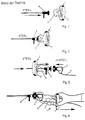
- Figures 1 to 4 show a typical application example of a known film tube cover.
- the sterile part 4 of a medical device is guided to a certain extent through a holding ring 2 and, if appropriate, an opening at the end of the film tube 3.
- the free end of the film tube 3 is turned inside out on the right side according to FIG. 3, wherein the plug-in film tube 3 can partially unfold.
- the non-sterile part 5 of the medical device is then connected to the sterile part 4 of the medical device, the free end of the film tube possibly being clamped between these two parts.
- the medical personnel pulls the retaining ring 2 over the elongated cable 7 in order to cover the elongated cable 7 with the film tube 3 and thus to ensure sterility.
- FIG. 4 it can easily happen that the medical personnel touches the sterile outside of the film tube 3 with the fingertips, whereby the film tube 3 can become non-sterile.
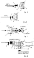
- FIGS. 5 to 8 show the use of a preferred embodiment of the film tube cover 1 according to the invention.
- the retaining ring 2 On the side facing the sterile part 4 of the medical device, the retaining ring 2 has a grip guard 6 arranged coaxially with the film tube 3.
- the application of the film tube cover according to the invention essentially corresponds to the application of the known film tube cover.
- the grip protection 6 prevents the medical personnel from accidentally touching the sterile film tube 3 with the fingertips.
- the grip guard 6 can be formed, for example, in one piece with the retaining ring 2 or with part of the retaining ring 2. This embodiment is particularly useful when the handle guard 6 is formed by a relatively rigid material.
- the grip guard 6 is formed by the end section of the film tube 3, which is attached to the retaining ring 2. In this case, it is sufficient to turn over the end section of the film tube 3 provided for attachment to the holding ring 2 before the film tube 3 is attached to the holding ring 2 in a suitable manner. Because the handle guard in this embodiment is formed by the flexible film tube 3, it is possible to lay the handle guard 6 flat for transport and storage or to wrap it in the retaining ring 2. The space required for storage or transport is then no larger than in the case of known film tube covers.
Abstract
Description
Die Erfindung bezieht sich auf eine Folienschlauchabdeckung für medizinische Geräte.The invention relates to a film tube cover for medical devices.
Bei vielen medizinischen Geräten, beispielsweise bei Endoskopen oder Arthroskopiekameras sind diese medizinischen Geräte mit Steuer- und Auswerteeinrichtungen über langgestreckte Schläuche und/oder Kabel verbunden, die mit sterilen Abdeckungen versehen werden müssen.In many medical devices, for example in endoscopes or arthroscopy cameras, these medical devices are connected to control and evaluation devices via elongated tubes and / or cables which have to be provided with sterile covers.
Zu diesem Zweck ist es bereits bekannt, Folienschlauchabdeckungen zu verwenden, die vor dem Gebrauch mit Hilfe einer sogenannten Steckfaltung auf eine sehr kurze Länge teleskopartig zusammengeschoben oder gefaltet sind, wobei an einem Ende dieses Folienschlauches ein Haltering befestigt ist, der gleichzeitig zur Aufnahme des in seiner Länge verkürzten Folienschlauches vor Gebrauch verwendet wird.For this purpose, it is already known to use film tube covers which are telescopically pushed or folded to a very short length before use with the aid of a so-called plug-in fold, a retaining ring being fastened to one end of this film tube and simultaneously holding the in its Length of shortened film tube is used before use.
Da die Halteringe derartiger Folienschlauchabdeckungen eine relativ geringe Breite (beispielsweise ca. 2 cm) aufweisen, kann es bei der Anwendung, d.h. wenn der Haltering über die langgestreckten Schläuche und/oder Kabel gezogen wird, um diese mit der Folienschlauchabdeckung abzudecken, dazu kommen, daß das medizinische Personal die sterile Außenseite der Schutzfolie mit den Fingern berührt, wodurch die Sterilität nicht mehr gewährleistet ist.Since the retaining rings of such film tube covers have a relatively small width (for example approx. 2 cm), it can if the retaining ring is pulled over the elongated tubes and / or cables in order to cover them with the foil tube cover, medical personnel may touch the sterile outside of the protective foil with their fingers, as a result of which sterility is no longer guaranteed.
Der Erfindung liegt deshalb die Aufgabe zugrunde, eine Folienschlauchabdeckung der eingangs genannten Art zu schaffen, bei deren Anwendung weitgehend ausgeschlossen werden kann, daß das medizinische Personal die sterile Außenseite der Folienschlauchabdeckung aus Versehen mit den Fingern berührt.The invention is therefore based on the object to provide a film tube cover of the type mentioned, the use of which can largely rule out that the medical personnel accidentally touches the sterile outside of the film tube cover with their fingers.
Diese Aufgabe wird durch die im Anspruch 1 angegebenen Merkmale gelöst.This object is achieved by the features specified in
Vorteilhafte Ausgestaltungen und Weiterbildungen der Erfindung ergeben sich aus den Unteransprüchen.Advantageous refinements and developments of the invention result from the subclaims.
Die Erfindung wird im folgenden anhand der Zeichnungen noch näher erläutert.The invention is explained in more detail below with reference to the drawings.
In den Zeichnungen zeigen:
Figuren 1 bis 4 die Anwendung einer bekannten Folienschlauchabdeckung,Figuren 5 bis 8 die Anwendung einer Ausführungsform der erfindungsgemäßen Folienschlauchabdeckung.
- FIGS. 1 to 4 show the use of a known film tube cover,
- Figures 5 to 8, the application of an embodiment of the film tube cover according to the invention.
Die Figuren 1 bis 4 zeigen ein typisches Anwendungsbeispiel einer bekannten Folienschlauchabdeckung.Figures 1 to 4 show a typical application example of a known film tube cover.
Um die insgesamt mit 1 bezeichnete Folienschlauchabdeckung anzuwenden, wird der sterile Teil 4 eines medizinischen Gerätes ein Stück weit durch einen Haltering 2 und ggf. eine Öffnung am Ende des Folienschlauches 3 geführt. Dabei wird das freie Ende des Folienschlauches 3 zur rechten Seite gemäß Figur 3 umgestülpt, wobei sich der steckgefaltete Folienschlauch 3 teilweise entfalten kann. Anschließend wird der unsterile Teil 5 des medizinischen Gerätes mit dem sterilen Teil 4 des medizinischen Gerätes verbunden, wobei das freie Ende des Folienschlauches dabei ggf. zwischen diesen beiden Teilen eingeklemmt wird. Nachdem die Teile 4 und 5 verbunden wurden, zieht das medizinische Personal den Haltering 2 über das langgestreckte Kabel 7, um das langgestreckte Kabel 7 mit dem Folienschlauch 3 abzudecken und damit die Sterilität zu gewährleisten. Wie dies in Figur 4 gezeigt ist, kann es dabei leicht dazu kommen, daß das medizinische Personal die sterile Außenseite des Folienschlauches 3 mit den Fingerspitzen berührt, wodurch der Folienschlauch 3 unsteril werden kann.In order to use the film tube cover, which is designated overall by 1, the
Die Figur 5 bis 8 zeigen die Anwendung einer bevorzugten Ausführungsform der erfindungsgemäßen Folienschlauchabdeckung 1.FIGS. 5 to 8 show the use of a preferred embodiment of the
Der Haltering 2 weist auf der dem sterilen Teil 4 des medizinischen Gerätes zugewandten Seite einen koaxial zum Folienschlauch 3 angeordneten Griffschutz 6 auf. Die Anwendung der erfindungsgemäßen Folienschlauchabdeckung entspricht im wesentlichen der Anwendung der bekannten Folienschlauchabdeckung. Wie dies insbesondere in Figur 8 deutlich gezeigt ist, wird durch den Griffschutz 6 jedoch verhindert, daß das medizinische Personal den sterilen Folienschlauch 3 versehentlich mit den Fingerspitzen berührt.On the side facing the
Der Griffschutz 6 kann beispielsweise einstückig mit dem Haltering 2 bzw. mit einem Teil des Halterings 2 ausgebildet sein. Diese Ausführungsform ist insbesondere dann sinnvoll, wenn der Griffschutz 6 durch ein relativ steifes Material gebildet ist.The
Selbstverständlich ist es ebenfalls denkbar, den Griffschutz 6 separat aus einem geeigneten Material herzustellen, und ihn anschließend auf irgendeine geeignete Weise am Haltering 2 zu befestigen.Of course, it is also conceivable to manufacture the
Weiterhin ist es denkbar, daß der Griffschutz 6 durch den Endabschnitt des Folienschlauchs 3 gebildet ist, der am Haltering 2 befestigt ist. In diesem Fall genügt es, den zur Befestigung am Haltering 2 vorgesehenen Endabschnitt des Folienschlauches 3 umzuschlagen, bevor der Folienschlauch 3 auf geeignete Weise am Haltering 2 befestigt wird. Weil der Griffschutz bei dieser Ausführungsform durch den flexiblen Folienschlauch 3 gebildet ist, ist es möglich, den Griffschutz 6 zum Transport und zur Lagerung flachzulegen bzw. ihn in den Haltering 2 einzuschlagen. Der zur Lagerung bzw. zum Transport erforderliche Raum ist dann nicht größer als bei bekannten Folienschlauchabdeckungen.Furthermore, it is conceivable that the
Claims (5)
dadurch gekennzeichnet, daß sie auf der dem sterilen Teil (4) des medizinischen Gerätes zugewandten Seite einen Griffschutz (6) aufweist, der koaxial zu dem Folienschlauch (3) angeordnet ist und sich über die axiale Länge des Halteringes (2) erstreckt.Foil tube cover (1) for medical devices (4, 5), with a retaining ring (2), with a foil tube (3) of considerable length, which is shortened by folding so far that it can be stored in the retaining ring (2), whereby an end section of the film tube (3) is attached to the retaining ring (2),
characterized in that it has on the side facing the sterile part (4) of the medical device a handle guard (6) which is arranged coaxially with the film tube (3) and extends over the axial length of the retaining ring (2).
dadurch gekennzeichnet, daß der Griffschutz (6) einstückig mit dem Haltering (2) oder einem Teil des Halterings (2) gebildet ist.Foil tube cover according to claim 1,
characterized in that the handle guard (6) is formed in one piece with the retaining ring (2) or part of the retaining ring (2).
dadurch gekennzeichnet, daß der Griffschutz (6) separat aus Kunststoff und/oder Kunststoff-Folie gebildet und auf geeignete Weise am Haltering (2) befestigt ist.Foil tube cover according to claim 1,
characterized in that the handle guard (6) is formed separately from plastic and / or plastic film and is attached in a suitable manner to the retaining ring (2).
dadurch gekennzeichnet, daß der Griffschutz (6) durch den umgeschlagenen Endabschnitt des Folienschlauches (3) gebildet ist, der am Haltering (2) befestigt ist.Foil tube cover according to claim 1,
characterized in that the handle guard (6) is formed by the folded-over end section of the film tube (3) which is attached to the retaining ring (2).
dadurch gekennzeichnet, daß der Griffschutz (6) vor Gebrauch auf eine axiale Stirnfläche des Halterings (2) flach umgelegt und/oder zumindest teilweise in den Haltering eingeschlagen ist.Foil tube cover according to one of the preceding claims,
characterized in that the handle guard (6) is folded flat on an axial end face of the retaining ring (2) before use and / or at least partially hammered into the retaining ring.
Applications Claiming Priority (2)
| Application Number | Priority Date | Filing Date | Title |
|---|---|---|---|
| DE29609565U | 1996-05-29 | ||
| DE29609565U DE29609565U1 (en) | 1996-05-29 | 1996-05-29 | Foil tube cover for medical devices |
Publications (3)
| Publication Number | Publication Date |
|---|---|
| EP0809976A2 true EP0809976A2 (en) | 1997-12-03 |
| EP0809976A3 EP0809976A3 (en) | 1997-12-17 |
| EP0809976B1 EP0809976B1 (en) | 2003-05-21 |
Family
ID=8024546
Family Applications (1)
| Application Number | Title | Priority Date | Filing Date |
|---|---|---|---|
| EP97102758A Expired - Lifetime EP0809976B1 (en) | 1996-05-29 | 1997-02-20 | Tubular foil cover for medical use |
Country Status (4)
| Country | Link |
|---|---|
| EP (1) | EP0809976B1 (en) |
| AT (1) | ATE240685T1 (en) |
| DE (1) | DE29609565U1 (en) |
| ES (1) | ES2195043T3 (en) |
Cited By (5)
| Publication number | Priority date | Publication date | Assignee | Title |
|---|---|---|---|---|
| EP1518491A1 (en) * | 2003-09-23 | 2005-03-30 | Udo Heisig GmbH | Adapter for connecting a camera with a medical endoscope |
| US20070042488A1 (en) * | 2001-02-07 | 2007-02-22 | Reinhard Bornemann | Cell spraying device, method and sprayed cell suspension |
| US9505000B2 (en) | 2011-04-27 | 2016-11-29 | Renovacare Sciences Corp. | Device for cell spraying, manufacturing of the device, method for spraying with the device and a cell suspension sprayed with the device |
| US9610430B2 (en) | 2006-09-11 | 2017-04-04 | Renovacare Sciences Corp. | Cell spraying device, method and sprayed cell suspension |
| WO2017218549A1 (en) * | 2016-06-14 | 2017-12-21 | Renovacare Sciences Corp. | Modular device for cell spraying |
Families Citing this family (3)
| Publication number | Priority date | Publication date | Assignee | Title |
|---|---|---|---|---|
| FR2819404B1 (en) | 2001-01-12 | 2004-11-05 | Oreal | COSMETIC COMPOSITIONS CONTAINING A FRUCTANE AND A CATIONIC POLYMER AND USES THEREOF |
| WO2002091937A1 (en) * | 2001-05-17 | 2002-11-21 | Pieter Rousseau Fourie | Disposable medical equipment and its packaging |
| DE102007009765B3 (en) * | 2007-02-27 | 2008-08-28 | Riess, Guido, Prof. Dr. | Room e.g. practice room, transformation method for e.g. clinic, involves placing gastight casing in room so that treatment unit is produced, and sterilizing surfaces in treatment unit before and/or after placing casing |
Citations (3)
| Publication number | Priority date | Publication date | Assignee | Title |
|---|---|---|---|---|
| EP0360951A2 (en) * | 1988-09-23 | 1990-04-04 | Dunsch-Herzberg, Renate | Disposable thin-walled tube covering for an arthroscopy camera, and use thereof |
| US5325846A (en) * | 1992-07-27 | 1994-07-05 | Linvatec Corporation | Endoscopic draping apparatus and method |
| DE9418340U1 (en) * | 1994-11-15 | 1995-01-19 | Heisig Udo Gmbh | Retaining ring for a film tube cover |
-
1996
- 1996-05-29 DE DE29609565U patent/DE29609565U1/en not_active Expired - Lifetime
-
1997
- 1997-02-20 AT AT97102758T patent/ATE240685T1/en active
- 1997-02-20 ES ES97102758T patent/ES2195043T3/en not_active Expired - Lifetime
- 1997-02-20 EP EP97102758A patent/EP0809976B1/en not_active Expired - Lifetime
Patent Citations (3)
| Publication number | Priority date | Publication date | Assignee | Title |
|---|---|---|---|---|
| EP0360951A2 (en) * | 1988-09-23 | 1990-04-04 | Dunsch-Herzberg, Renate | Disposable thin-walled tube covering for an arthroscopy camera, and use thereof |
| US5325846A (en) * | 1992-07-27 | 1994-07-05 | Linvatec Corporation | Endoscopic draping apparatus and method |
| DE9418340U1 (en) * | 1994-11-15 | 1995-01-19 | Heisig Udo Gmbh | Retaining ring for a film tube cover |
Cited By (9)
| Publication number | Priority date | Publication date | Assignee | Title |
|---|---|---|---|---|
| US20070042488A1 (en) * | 2001-02-07 | 2007-02-22 | Reinhard Bornemann | Cell spraying device, method and sprayed cell suspension |
| EP1518491A1 (en) * | 2003-09-23 | 2005-03-30 | Udo Heisig GmbH | Adapter for connecting a camera with a medical endoscope |
| US9610430B2 (en) | 2006-09-11 | 2017-04-04 | Renovacare Sciences Corp. | Cell spraying device, method and sprayed cell suspension |
| US9505000B2 (en) | 2011-04-27 | 2016-11-29 | Renovacare Sciences Corp. | Device for cell spraying, manufacturing of the device, method for spraying with the device and a cell suspension sprayed with the device |
| US10376658B2 (en) | 2011-04-27 | 2019-08-13 | Renovacare Sciences Corp. | Device for cell spraying |
| US11135380B2 (en) | 2011-04-27 | 2021-10-05 | Renovacare Sciences Corp. | Device for cell spraying |
| WO2017218549A1 (en) * | 2016-06-14 | 2017-12-21 | Renovacare Sciences Corp. | Modular device for cell spraying |
| JP2019530562A (en) * | 2016-06-14 | 2019-10-24 | レノバケア・サイエンシズ・コーポレイション | Modular device for cell spraying |
| US11040363B2 (en) | 2016-06-14 | 2021-06-22 | Renovacare Sciences Corp. | Modular device for cell spraying |
Also Published As
| Publication number | Publication date |
|---|---|
| EP0809976B1 (en) | 2003-05-21 |
| DE29609565U1 (en) | 1996-08-22 |
| EP0809976A3 (en) | 1997-12-17 |
| ES2195043T3 (en) | 2003-12-01 |
| ATE240685T1 (en) | 2003-06-15 |
Similar Documents
| Publication | Publication Date | Title |
|---|---|---|
| DE4008392C2 (en) | ||
| DE2150595C3 (en) | Endoscope with controllable, flexible tube made of helically wound strips | |
| EP0437004B1 (en) | Foil cover for the protection of a surgical instrument | |
| EP2229120B1 (en) | Tubular film cover for medical devices | |
| EP0371909A1 (en) | Sheath for the protection of a surgical instrument | |
| EP0360951A2 (en) | Disposable thin-walled tube covering for an arthroscopy camera, and use thereof | |
| EP0809976B1 (en) | Tubular foil cover for medical use | |
| EP2093161A1 (en) | Packaging unit with support section | |
| EP3247283B1 (en) | Device for firmly clamping a medical guide wire | |
| DE7821507U1 (en) | PROTECTIVE SLEEVE FOR A QUARTZ LIGHT GUIDE | |
| CH645528A5 (en) | TELESCOPICABLE GUIDE FOR HOUSEHOLD APPLIANCES, ESPECIALLY FOR VACUUM CLEANERS. | |
| EP0784178A1 (en) | Protective pipe sealing device | |
| DE3206846A1 (en) | MECHANICAL LITHOTRIPTOR | |
| DE102010010798A1 (en) | Hand-operated functional hose instrument and operating device therefor | |
| DE202020003344U1 (en) | Medical spreading device | |
| EP0918489A1 (en) | Trocar sheath for endoscopic use | |
| DE19948637A1 (en) | Treatment tool for endoscope, has pair of flexible cylindrical fold prevention tube which are overlapped and arranged on sheath, whose length differs by protruding forward one tube from other | |
| EP1252854B1 (en) | Tube connector for the suction tube of a vacuum cleaner | |
| DE19857340C2 (en) | Cable gland for cables with shielding sheath | |
| EP0205757A1 (en) | Folded fibre block | |
| DE4442185C2 (en) | guide | |
| CH631898A5 (en) | Sleeve for protecting a tubular apparatus, and a sterile packaging | |
| DE102021105244B3 (en) | endoscope | |
| EP0761158B1 (en) | Tubular foil cover | |
| DE2247253A1 (en) | CABLE JOINT |
Legal Events
| Date | Code | Title | Description |
|---|---|---|---|
| PUAI | Public reference made under article 153(3) epc to a published international application that has entered the european phase |
Free format text: ORIGINAL CODE: 0009012 |
|
| PUAL | Search report despatched |
Free format text: ORIGINAL CODE: 0009013 |
|
| AK | Designated contracting states |
Kind code of ref document: A2 Designated state(s): AT ES FR GB IT |
|
| AK | Designated contracting states |
Kind code of ref document: A3 Designated state(s): AT ES FR GB IT |
|
| 17P | Request for examination filed |
Effective date: 19980610 |
|
| 17Q | First examination report despatched |
Effective date: 20020204 |
|
| GRAH | Despatch of communication of intention to grant a patent |
Free format text: ORIGINAL CODE: EPIDOS IGRA |
|
| GRAH | Despatch of communication of intention to grant a patent |
Free format text: ORIGINAL CODE: EPIDOS IGRA |
|
| GRAA | (expected) grant |
Free format text: ORIGINAL CODE: 0009210 |
|
| AK | Designated contracting states |
Designated state(s): AT ES FR GB IT |
|
| PG25 | Lapsed in a contracting state [announced via postgrant information from national office to epo] |
Ref country code: IT Free format text: LAPSE BECAUSE OF FAILURE TO SUBMIT A TRANSLATION OF THE DESCRIPTION OR TO PAY THE FEE WITHIN THE PRE;WARNING: LAPSES OF ITALIAN PATENTS WITH EFFECTIVE DATE BEFORE 2007 MAY HAVE OCCURRED AT ANY TIME BEFORE 2007. THE CORRECT EFFECTIVE DATE MAY BE DIFFERENT FROM THE ONE RECORDED.SCRIBED TIME-LIMIT Effective date: 20030521 Ref country code: GB Free format text: LAPSE BECAUSE OF FAILURE TO SUBMIT A TRANSLATION OF THE DESCRIPTION OR TO PAY THE FEE WITHIN THE PRESCRIBED TIME-LIMIT Effective date: 20030521 |
|
| REG | Reference to a national code |
Ref country code: GB Ref legal event code: FG4D Free format text: NOT ENGLISH |
|
| RAP2 | Party data changed (patent owner data changed or rights of a patent transferred) |
Owner name: UDO HEISIG GMBH |
|
| GBV | Gb: ep patent (uk) treated as always having been void in accordance with gb section 77(7)/1977 [no translation filed] |
Effective date: 20030521 |
|
| ET | Fr: translation filed | ||
| PLBE | No opposition filed within time limit |
Free format text: ORIGINAL CODE: 0009261 |
|
| STAA | Information on the status of an ep patent application or granted ep patent |
Free format text: STATUS: NO OPPOSITION FILED WITHIN TIME LIMIT |
|
| 26N | No opposition filed |
Effective date: 20040224 |
|
| PGFP | Annual fee paid to national office [announced via postgrant information from national office to epo] |
Ref country code: FR Payment date: 20080219 Year of fee payment: 12 |
|
| REG | Reference to a national code |
Ref country code: FR Ref legal event code: ST Effective date: 20091030 |
|
| PG25 | Lapsed in a contracting state [announced via postgrant information from national office to epo] |
Ref country code: FR Free format text: LAPSE BECAUSE OF NON-PAYMENT OF DUE FEES Effective date: 20090302 |
|
| PGFP | Annual fee paid to national office [announced via postgrant information from national office to epo] |
Ref country code: AT Payment date: 20120301 Year of fee payment: 16 |
|
| PGFP | Annual fee paid to national office [announced via postgrant information from national office to epo] |
Ref country code: ES Payment date: 20120227 Year of fee payment: 16 |
|
| REG | Reference to a national code |
Ref country code: AT Ref legal event code: MM01 Ref document number: 240685 Country of ref document: AT Kind code of ref document: T Effective date: 20130228 |
|
| PG25 | Lapsed in a contracting state [announced via postgrant information from national office to epo] |
Ref country code: AT Free format text: LAPSE BECAUSE OF NON-PAYMENT OF DUE FEES Effective date: 20130228 |
|
| REG | Reference to a national code |
Ref country code: ES Ref legal event code: FD2A Effective date: 20140410 |
|
| PG25 | Lapsed in a contracting state [announced via postgrant information from national office to epo] |
Ref country code: ES Free format text: LAPSE BECAUSE OF NON-PAYMENT OF DUE FEES Effective date: 20130221 |