EP0810558A2 - Advanced maintenance system for aircraft and military weapons - Google Patents
Advanced maintenance system for aircraft and military weapons Download PDFInfo
- Publication number
- EP0810558A2 EP0810558A2 EP97108495A EP97108495A EP0810558A2 EP 0810558 A2 EP0810558 A2 EP 0810558A2 EP 97108495 A EP97108495 A EP 97108495A EP 97108495 A EP97108495 A EP 97108495A EP 0810558 A2 EP0810558 A2 EP 0810558A2
- Authority
- EP
- European Patent Office
- Prior art keywords
- data
- maintenance
- equipment
- aircraft
- central
- Prior art date
- Legal status (The legal status is an assumption and is not a legal conclusion. Google has not performed a legal analysis and makes no representation as to the accuracy of the status listed.)
- Granted
Links
Images
Classifications
-
- G—PHYSICS
- G06—COMPUTING; CALCULATING OR COUNTING
- G06Q—INFORMATION AND COMMUNICATION TECHNOLOGY [ICT] SPECIALLY ADAPTED FOR ADMINISTRATIVE, COMMERCIAL, FINANCIAL, MANAGERIAL OR SUPERVISORY PURPOSES; SYSTEMS OR METHODS SPECIALLY ADAPTED FOR ADMINISTRATIVE, COMMERCIAL, FINANCIAL, MANAGERIAL OR SUPERVISORY PURPOSES, NOT OTHERWISE PROVIDED FOR
- G06Q10/00—Administration; Management
- G06Q10/06—Resources, workflows, human or project management; Enterprise or organisation planning; Enterprise or organisation modelling
-
- B—PERFORMING OPERATIONS; TRANSPORTING
- B64—AIRCRAFT; AVIATION; COSMONAUTICS
- B64D—EQUIPMENT FOR FITTING IN OR TO AIRCRAFT; FLIGHT SUITS; PARACHUTES; ARRANGEMENTS OR MOUNTING OF POWER PLANTS OR PROPULSION TRANSMISSIONS IN AIRCRAFT
- B64D7/00—Arrangements of military equipment, e.g. armaments, armament accessories, or military shielding, in aircraft; Adaptations of armament mountings for aircraft
-
- F—MECHANICAL ENGINEERING; LIGHTING; HEATING; WEAPONS; BLASTING
- F42—AMMUNITION; BLASTING
- F42B—EXPLOSIVE CHARGES, e.g. FOR BLASTING, FIREWORKS, AMMUNITION
- F42B35/00—Testing or checking of ammunition
Definitions
- the present invention relates generally to aircraft and military weapon maintenance and repair, and in particular to an advanced aircraft/weapon maintenance system that provides remote trouble-shooting and technical data access capabilities to technicians through a wireless link between a handheld point-of-maintenance transceiver and a central diagnostics center, thereby minimizing maintenance and repair time, costs and requisite paper reference materials.
- BIT built-in test
- the system will generate significant amount of information for analysis by the BIT logic.
- the BIT logic then automatically performs a system-wide nodal analysis and can generate equipment maintenance orders usually signalled by generation of a BIT flag, based upon a combination of BIT data and system operator observations. Therefore, a component identified may be repaired or replaced before the aircraft or weapon fails or malfunctions on the front line.
- BIT logic indicates that an aircraft or weapon requires repair and maintenance through generation of a BIT flag
- technicians must be dispatched to the remotely located weapon, or intermediate hub repair points must be set up for servicing of these remotely located aircraft or weapons. Due to the ever increasing complexity of the electronics implemented in such systems, the technicians must exhibit a high level of training and have a high level of associated skill to repair the associated equipment. In addition, the technicians must have technical reference materials available to correctly locate and identify a flagged problem. For instance, it is estimated that the F-15 aircraft has an associated 16,000 pounds of associated technical data, paper reference materials, parts and repairs manuals, and other related reference materials.
- an advanced maintenance system that utilizes existing system hardware and software, along with on-line technical expertise, to substantially enhance maintenance and repair of equipment such as aircraft and military weapons to reduce and/or eliminate removal of fully functional system components.
- the maintenance system of the present invention utilizes wireless transceivers or a combination of high speed land lines and wireless transceivers, in communication with a central data warehouse. These wireless transceivers eliminate the volumes of technical manuals and maintenance information typically associated with equipment repair facilities and reduce requisite parts inventories at repair depots.
- the maintenance system of the present invention also initiates and logs repair actions and work orders, thereby eliminating the need for paper tracking of repairs.
- the system also provides historical maintenance data for a particular aircraft or weapon.
- the maintenance system of the present invention thereby provides an information management solution to a problem that has characteristically been treated as hardware-based.
- the present invention provides a maintenance system for remotely located equipment comprising a central data storage warehouse for electronically storing technical information and for providing on-line technical assistance for repairing the remotely located equipment.
- a data transceiver transmits data to and receives data from the central data storage subsystem.
- a communications link between the central data storage subsystem and the wireless data transceiver enables accessing of the technical information from the central data storage warehouse by the data transceiver.
- test means is implemented to correctly identify failed system components, and thus minimize unnecessary pulls of operational equipment.
- FIG. 1 illustrates an aircraft/weapon maintenance system according to a preferred embodiment of the present invention generally at 10.
- the aircraft/weapon maintenance system of the present invention represents a new way of approaching the test and diagnostics of both aircraft, or other transport craft such as tanks or ships, and military weapons, starting at the system level or the serial numbered assembly and embracing all higher test levels.
- the weapon system of the present invention utilizes commercial, off-the-shelf hardware and information retrieval systems, existing technical and maintenance information, and a software-implemented enhancement for existing system-level BIT logic, integrated into a single system.
- the weapon system of the present invention achieves dramatic improvements in fault-detection and fault-isolation accuracy, with attendant reductions in false removals of fully functional components from aircraft, military weapons, or other systems requiring maintenance at locations remote from a central maintenance facility. These results enable substantial reductions in overall aircraft/weapon logistics footprints, reduce spare component requirements, and provide reduced depot (permanently installed facility dedicated to high volume repair of units, such as F-ISEs, requiring special engineering support and facilities) and (I-Level intermediate repair point deployable with forces at a permanent operating location) workloads.
- a portable maintenance aid (PMA) 12 is provided for use by a repair technician.
- the PMA may be used along with conventional aircraft/weapon BIT logic, to remotely troubleshoot an aircraft/weapon 14, shown with an associated display 15, for component fault isolation. While reference will be made throughout to an aircraft or weapon, it should be understood that the system represented at 14 may also be any other type of system, such as tanks, ships, or other vehicles, requiring periodic maintenance or repair.
- the PMA or, optionally, a conventional desktop computer also provides on-line access of a central data warehouse 16 for real-time communications and transmittal of technical information and data, plus initialization and population of repair/work orders.
- the central data warehouse includes a technical information database 18 that maintains electronic technical order and technical manual libraries, and a master maintenance history database 20 for all weapons entered into the system.
- the PMA 12 communicates with the central data warehouse 16 trough a radio link 22, which may be a local area network operating at an FM ground net frequency, or any other similar radio link such as those commercially available from companies such as Proxin and Cylink.
- the radio link is in operative communication with both a deployed file server 24 and a satellite terminal 26.
- the satellite terminal bi-directionally relays radio signals transmitted across the radio link to a satellite system 28.
- the satellite system 28 in turn relays the signals to a satellite broadcast station 30 operatively associated with the central data warehouse 16.
- the PMA 12 is a key element of the maintenance system of the present invention, as it delivers critical maintenance-related data in real time to and from the point of use.
- the PMA is preferably a commercially available hand-held computer such as the units manufactured by Paravant Computer Systems, Allied Signal Aerospace, computing Devices International and SAIC.
- the PMA preferably has a nominal weight of 5 to 7 pounds, and includes the associated radio link 22.
- the PMA is capable of providing a technician with maintenance procedures, illustrations and parts lists downloaded in real time from the central data warehouse 16 to aid the technician in repair/maintenance work and eliminate paper reference materials. Additionally, the PMA of the present invention automatically generates a network repair order subsequent to isolation of the problem at the aircraft or weapon.
- the PMA 12 is implemented to provide automated download of BIT data from an aircraft or weapon bus if the weapon or aircraft is appropriately configured.
- a convenient means to extract a significant amount of BIT and related aircraft performance parameters presently exists on aircraft such as the F-15, F-18, and F-16.
- a Data Transfer Module (DTM) or Data Transfer cartridge (DTC) exists on these aircraft to record test and performance parameters during each aircraft sortie or mission.
- the DTM or DTC may be removed from the aircraft and downloaded off-line (on the F-15 and F-18 this is known as a Computerized Fault Reporting System or CFRS) during the official pilot debrief.
- CFRS Computerized Fault Reporting System
- the maintenance system 10 of the present invention can automate this process and provide direct interface to the central data warehouse 16.
- the base file server 24 is a control and interface unit for storing data requested by the PMA and the central data warehouse.
- the file server also functions as a data re-entry point for repopulation of new data at the maintenance database 16. Blocks of information may also be downloaded to the file server for local non-real-time access as needed.
- the file server 24 is hooked to the commercial satellite terminal 26.
- the satellite terminal 26 enables real-time communication via satellite between the PMA 12 and the central data warehouse 16.
- the satellite system 28 is of the type that is commercially available and which utilizes low-cost, commercial ground stations incorporating Very Small Aperture Terminals (VSAT) with 1 to 2 meter antennas, such as the satellite terminal 26.
- VSAT Very Small Aperture Terminals
- the system 28 provides the system 10 of the present invention with real-time, on-line satellite communications capability.
- one main operating terminal located at the data warehouse 16 or at the file server 24 and utilized for each maintenance activity can communicate with a plurality of PMAs in use via the FM ground net radio link 22. Requests for relevant portions of current technical orders or technical manuals for the particular aircraft or weapon under analysis are made by a technician at the PMA 12 through the VSAT, which preferably has a narrow-band (128 Kbytes/sec) uplink capability.
- the request is then downloaded via wideband downlink (512 kb/sec) to the central data warehouse 16. It is contemplated that these data rates will increase as the associated technology matures. This download eliminates the need to distribute and control the electronic format.
- PC-based terminals may also be interconnected to the satellite system to provide real-time communications capability to the central data warehouse.
- the satellites that are planned for use are extremely reliable and multiple redundant. Typically these satellites operate on either Ku-band or C-Band frequency. Such satellites are typically in constant use for a variety of commercial applications. Therefore, there is no associated loss of service or data integrity when the system of the present invention is implemented using the satellites. Communications channel space may be procured on an average-demand basis if the system of the present invention is implemented in a commercial application. There is substantial bandwidth available, as communications satellites are multi-channel, multi-transponder systems.
- Satellites such as those owned by Hughes Electronics, assignee of the present invention, provide full coverage for the United States and Europe, and Hughes business partners, including TRW, General Electric, Hughes-Olivetti, IMPSAT, and numerous others provide essentially the remainder of full global coverage. Longer distances may require the use of more than one satellite; however, this requirement is transparent to the user. Nominal satellite delays of approximately 250-500 milliseconds may be associated with system transmissions.
- high speed land lines such as co-axial, telephonic twisted pair, electro-optic cable, or other similar lines could also be used exclusively, or in combination with, satellite lines to supplement the present invention.
- central data warehouse 16 Instructions from the central data warehouse 16 are provided via the satellite system 28 directly to the technician performing tests on the aircraft or weapon 14, along with illustrations and other pertinent information. Expert help from experienced technicians is also available at the central data warehouse facility. Since one location serves all users, it is conceivable that a 24-hour staff of experts in each aircraft or weapon system be available full time to assist in resolving difficult maintenance problems.
- the interactive electronic technical manual (IETM) and library database 18 is implemented at the central data warehouse 16.
- This IETM library database may be accessed by PMAs in remote operating locations via the radio link 22 and satellite system 28.
- the technical library is created from any source documentation, technical manuals, Logistics Support Analysis Record (LSAR), parts illustration, or like record.
- LSAR Logistics Support Analysis Record
- the central data warehouse 16 Upon receiving a request for information from a particular technical manual, the central data warehouse 16 automatically pulls the correct repair procedure, including all recent revisions, based upon the transmitted symptoms and diagnosed fault at the aircraft or weapon 14. This information is then sent to the requesting PMA. Subsequently, the PMA displays correct diagrams/chromatics/part listings and interchangeability to the technician.
- the technical manual database 18 may direct a guided probe and perform additional tests and observations in order to unambiguously isolate the fault occurring at the aircraft or weapon.
- Such an electronic technical manual database thereby eliminates the need to distribute paper or CD ROM copies of any technical orders or manuals to field technicians and eliminates the need for on-site configuration management of these operating manuals.
- the central data warehouse 16 will also accommodate standard technical manuals in raster or vector scan format.
- the central data warehouse 16 contains all technical order information in either IETM or raster/vector format, in the technical database 18.
- technical order/technical maintenance manual (TO/TM) data is maintained only at the central data warehouse, which is implemented via distributed database methodology, and downloaded only upon demand to the PMA. This eliminates the need to continuously update, print, distribute, and maintain paper copies of TO/TMs, and the need to cross-reference by Serial Number (SERNO) and configuration break-in-point.
- SERNO Serial Number
- TO/TM change As soon as a TO/TM change is approved, it is immediately available to all field technicians. Maintenance procedures, illustrations from an illustrated parts breakdown reference, parts listings, interchangeability data, and provision-type data are all available real-time, on-line, to the technician at the flight line or the point of maintenance. Alternatively, the information may be downloaded periodically to an intermediate database, such as the file server 24, which in turn functions as the point of access for the PMA 12.
- an intermediate database such as the file server 24, which in turn functions as the point of access for the PMA 12.
- this BIT flag may be any type of indicator that represents a problem identified by system BIT logic. For example, if a component often exhibits erroneous fault symptoms when installed in a particular aircraft or weapon, such information is provided to the technician.
- the maintenance database is tied in to all levels of maintenance, and is populated in real-time by each repair activity as maintenance actions are initiated and completed.
- This feature allows real-time analysis of reliability and maintainability factors on a weapon by weapon or aircraft by aircraft basis.
- the logged maintenance actions are already present upon arrival of a suspected faulty component. As soon as repairs to the unit are complete, this maintenance action is immediately available throughout the entire system.
- the maintenance database 20 also logs and tracks all maintenance actions, thereby eliminating the need for paper forms to document maintenance actions.
- Work/repair orders are opened at the point of use, data is entered by the technician using the PMA. This information is available to all users instantaneously.
- the maintenance history of an aircraft or weapon is updated automatically.
- the data is entered into the system via standard PC-based terminals. Real-time trend analysis is also performed by the system, as well as continuous tracking by serial number of every repairable component in the system. It is contemplated that custom sub-routines may also be implemented to extract visibility data for management and budgeting purposes.
- An initial system can be configured to deliver paperless technical manuals to desk-top PC-based terminals on demand.
- Such a paperless system eliminates the extraordinary delay in printing, distributing and disseminating technical manuals once the manuals have been approved for use.
- the manuals are merely loaded into the system and are immediately available world-wide to all users. Maintenance data tracking can be added at a later time.
- the aircraft/weapon maintenance system 10 of the present invention also includes an optional feature BIT modeling logic, referred to as virtual testability, that is capable of substantially enhancing the diagnosis of failed weapon system components.
- virtual testability logic will be described as it is implemented in conjunction with an F-15 radar system. However, it is contemplated that this logic may be implemented in other environments in which the maintenance system of the present invention is implemented.
- the logic incorporates the logic of several different tests that, when implemented with the on-board diagnostics of the weapon or aircraft 14, provide a high degree of success in minimizing removal of still-operational system components.
- the virtual testability logic thoroughly analyzes existing data and may be implemented with little or no changes to existing aircraft system hardware.
- the virtual testability logic utilizes a nodal analysis to map performance-related parameters, along with existing test access, to provide a more comprehensive assessment of performance than would normally be accomplished by the existing BIT logic alone.
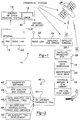
- test blocks representing several sequences of virtual testability logic implemented in conjunction with an F-15 radar system are shown generally at 40.
- a commercially available analytical program known as Diagnostician and owned by Giordano Automation, Inc. of Sparta, New Jersey, is shown at block 42.
- the Diagnostician program utilizes a mapped diagnostic knowledge base and an artificial intelligence inference engine, mapped into aircraft tactical software, such as the operational flight program in the F-15.
- Other modeling techniques for BIT mapping are available and equally applicable.
- the Diagnostician program also includes several engineering tools having the capability of providing a technician with statistical reports on the quality of the data being accumulated by the knowledge base.
- the test database on which the Diagnostician can operate There is virtually no limit to the size of the test database on which the Diagnostician can operate. Therefore, it can be utilized vertically at any of the well-known tactical, organizational, intermediate, depot and manufacturing levels of test to provide automatic component fault isolation.
- the quality of fault isolation is a direct function of the quantity and quality of available diagnostics information and system design detail.
- Diagnostician-generated test data can be input to its knowledge base.
- the knowledge base of the Diagnostician program is enriched at each inquiry through its access to the current worldwide histogram of similar fault frequencies across the entire fleet of operational aircraft.
- an Operational Flight Complex (OFP) program is shown.
- Complex avionics are generally software controlled via an OFP running in one or more imbedded or external processors.
- Radar OFPs are extremely complex and inevitably contain bugs such as algorithmic or coding errors. These bugs can be caused by errors in the software or by artifacts that, under certain inflight circumstances, can drive the hardware into an unknown state, thus setting a BIT component failure flag. The phenomena can occur often, rarely, or not manifest itself for years until age has caused a hardware performance decrease.
- a BIT flag When set, a BIT flag, such as that shown at 32 in FIG. 1, causes a maintenance action to take place. If the technician can not verify the cause of the BIT indicated failure at the plane, he must remove the most probable faulty component, or line replaceable unit (LRU), for further testing and repair in a forward area intermediate shop or at a rear echelon depot repair facility. The reason for the BIT indication may be duplicated and repaired at those facilities. However, typically around 50% of such failures are not duplicated when so tested. The OFP applies current knowledge and advanced analytical tools to identify, remove or operate around the cause of this class of BIT failure indications.
- LRU line replaceable unit
- test block 46 there have been several attempts to alleviate false LRU pull problems through analysis of voluminous existing maintenance data for patterns, ancillary symptoms, or other existing but unrecognized diagnostic clues. Some success has been achieved, but a system level analysis has not been accomplished in most cases. Indications are that such an analysis would contribute significantly to the overall solution being pursued. The data analysis approach of block 46 would collate previous analytical efforts, identify the parameters of success so achieved, and do a system level analysis of other such parameters that contribute to the overall virtual testability concept.
- test block 48 In the current repair cycle, BIT and built in self tests (BIST) identify a failure and generate a BIT flag. Depending on the specific aircraft and sophistication of the application, some diagnostic action must take place before a repair is made. Generally, this diagnostic activity is performed using automated test equipment (ATE) at the aircraft itself, in an intermediate shop, or at the depot repair facility. At each level, the ATE is significantly different, having been built for field deployability or permanent residence in a depot. The tests applied are different as well. These different test routines yield inconsistent results.
- ATE automated test equipment
- test block 50 Current BIT/BIST and on-aircraft ATE does not use all information available to perform an accurate diagnosis.
- radar systems have test ports that give access to bus IO traffic and other information used in manufacturing check out and initial integration.
- On board maintenance recorders may be enhanced to record more or more pertinent inflight data. Radar sets constantly calibrate internally; this data often highlights component failure but is not currently used in diagnostic processes. Implementation of test block 50 to access the above data, coupled with advanced analytical programs, provides additional improvement of the maintenance system of the present invention.
- test block 52 When the above test sequences indicated in blocks 42-50 are integrated to form the virtual testability logic, the tests, in combination with the on-aircraft diagnostics tools represented in test block 52, substantially reduce the false removal rate of operational system components.
- the virtual testability logic is an optional feature of the maintenance system which enhances BIT logic accuracy. However, the remaining portions of the maintenance system of the present invention are fully functional apart from the new logic. It should also be appreciated that the virtual testability logic described above may be applied to any system requiring regular repair and testing of components.
- data to be uploaded or downloaded through the maintenance system of the present invention can also be encrypted in situations where access to the data or contamination thereof has to be rigorously avoided.
- Standard encryption methods such as now used in long-distance communications are employed in such cases.
- the weapon maintenance system of the present invention greatly simplifies the job of the technician. All pertinent test/trouble shooting/maintenance information is available immediately at the flight line, allowing all suspect faults and squawks to be accurately and efficiently resolved. Excess use of spare components due to false removals is nearly eliminated, maintenance times are significantly reduced, TO distribution/configuration control/update problems are eliminated, and maintenance data analysis is provided automatically, in real-time.
- the weapon maintenance system of the present invention reduces overall maintenance costs in several areas.
- overall systems cost is reduced through the minimizing of the number of spare components required to be kept in inventory, as the maintenance system of the present invention requires use of spare parts only when the parts or components are truly needed.
- the system of the present invention provides ease of configuration management in that only one copy of Test Program Set (TPS) and one copy of TO must be maintained in the central data warehouse. No field Time Compliance Technical Orders (TCTOs) need be distributed in the current paper-based format.
- TPS Test Program Set
- TCTOs field Time Compliance Technical Orders
- the system of the present invention eliminates the need for warehouses to store technical orders and manuals, as the need for paper maintenance forms is eliminated.
- the system of the present invention improves the accuracy of aircraft/weapon repair and maintenance and reduces the skill level, experience level and number of technicians required for accurate and effective aircraft/weapon maintenance and repair.
- system 10 may be utilized for information storage and retrieval in connection with other systems requiring remote access to any large amount of data in real-time.
- systems include large commercial enterprises, such as trucking companies, automotive repair activities, and retail establishments or any other technical endeavor requiring technician or engineering access to a large and constantly updated information database where there is extensive field maintenance required or where on-line expertise, a centralized data reference database for technical manuals or product or component configuration history is stored and in which satellite-based communications networks can be implemented to reduce overall system cost.
Abstract
Description
- The present invention relates generally to aircraft and military weapon maintenance and repair, and in particular to an advanced aircraft/weapon maintenance system that provides remote trouble-shooting and technical data access capabilities to technicians through a wireless link between a handheld point-of-maintenance transceiver and a central diagnostics center, thereby minimizing maintenance and repair time, costs and requisite paper reference materials.
- A large number of currently deployed military aircraft and weapons, such as the F-15E aircraft, were designed in the late 1970's and early 1980's with built-in test (BIT) logic that indicates to a system operator when a system component has failed or requires maintenance. This BIT logic which is typically designed into a system and implemented on a system level through both hardware and software, reports system failures or malfunctions due to failure of one or more system components which the logic is designed to detect. These failures or malfunctions are made known to the system operator, such as an F-15 pilot, on a cockpit display through a BIT flag identifying the specific failure or malfunction.
- In operation, the system will generate significant amount of information for analysis by the BIT logic. The BIT logic then automatically performs a system-wide nodal analysis and can generate equipment maintenance orders usually signalled by generation of a BIT flag, based upon a combination of BIT data and system operator observations. Therefore, a component identified may be repaired or replaced before the aircraft or weapon fails or malfunctions on the front line.
- However, conventional BIT logic often generates maintenance orders for components when the components are in fact fully operational. As a result, fully operational components will often be pulled and replaced. Therefore, overall weapon/aircraft maintenance costs are increased due to the performance of such unnecessary maintenance procedures. The removal of fully operational components also increases the number of aircraft or weapons temporarily out of commission and increases the number of maintenance technicians required to service the equipment.
- In addition, once the BIT logic indicates that an aircraft or weapon requires repair and maintenance through generation of a BIT flag, technicians must be dispatched to the remotely located weapon, or intermediate hub repair points must be set up for servicing of these remotely located aircraft or weapons. Due to the ever increasing complexity of the electronics implemented in such systems, the technicians must exhibit a high level of training and have a high level of associated skill to repair the associated equipment. In addition, the technicians must have technical reference materials available to correctly locate and identify a flagged problem. For instance, it is estimated that the F-15 aircraft has an associated 16,000 pounds of associated technical data, paper reference materials, parts and repairs manuals, and other related reference materials. As updated technical data is published at regular periodic intervals, it is difficult at best for even the most highly skilled and trained technician to keep abreast of the most up-to-date information associated with each weapons system. Further, as such repair and component replacement must often be performed at locations remote from a central repair facility, the associated reference materials are often not readily available to the technicians when and where the materials are most needed. As is often the case, even updated reference materials are often months, or years, behind the most recently-implemented equipment.
- One possible solution to the above referenced limitations includes retrofitting all weapons systems with the most current technically advanced BIT and diagnostics equipment. Such equipment would minimize false pulls of still operative weapon components and would greatly reduce time and expense associated with weapon repair and maintenance.
- However, retrofitting weapons with this state-of-the-art technology is presently cost prohibitive and would require such systems to be removed from commission for a period of time while being retrofitted with the new equipment. In addition, such state-of-the-art technology would still require a significant amount of associated paper reference materials and would require technicians to maintain a high level of knowledge of the most current information on the equipment.
- Therefore, it would be desirable to provide a maintenance system for such aircraft and military weapons systems that would minimize the number of false pulls of still operative system components. It would also be desirable to provide a maintenance system that would eliminate the need for intermediate, or hub, repair facilities implemented remotely from a central station and that would virtually eliminate the associated paper-based technical reference materials. This would minimize the associated time and cost and maximize accuracy and efficiency of system repair and maintenance operations.
- In accordance with the teachings of the present invention, an advanced maintenance system is provided that utilizes existing system hardware and software, along with on-line technical expertise, to substantially enhance maintenance and repair of equipment such as aircraft and military weapons to reduce and/or eliminate removal of fully functional system components. The maintenance system of the present invention utilizes wireless transceivers or a combination of high speed land lines and wireless transceivers, in communication with a central data warehouse. These wireless transceivers eliminate the volumes of technical manuals and maintenance information typically associated with equipment repair facilities and reduce requisite parts inventories at repair depots. The maintenance system of the present invention also initiates and logs repair actions and work orders, thereby eliminating the need for paper tracking of repairs. The system also provides historical maintenance data for a particular aircraft or weapon. The maintenance system of the present invention thereby provides an information management solution to a problem that has characteristically been treated as hardware-based.
- In particular, the present invention provides a maintenance system for remotely located equipment comprising a central data storage warehouse for electronically storing technical information and for providing on-line technical assistance for repairing the remotely located equipment. A data transceiver transmits data to and receives data from the central data storage subsystem. A communications link between the central data storage subsystem and the wireless data transceiver enables accessing of the technical information from the central data storage warehouse by the data transceiver. Also, test means is implemented to correctly identify failed system components, and thus minimize unnecessary pulls of operational equipment.
- Other objects and advantages of the invention will become apparent upon reading the following detailed description and upon reference to the drawings, in which:
- FIG. 1 illustrates an overall system diagram of the maintenance system according to a preferred embodiment of the present invention; and
- FIG. 2 illustrates in block diagram form several hardware and software implemented test programs that, when implemented with an aircraft/weapon on board diagnostics tool, reduce the number of false pulls of operational equipment.
- The following description of the preferred embodiments is merely exemplary in nature and is in no way intended to limit the invention or its application or uses.
- Referring to the drawings, FIG. 1 illustrates an aircraft/weapon maintenance system according to a preferred embodiment of the present invention generally at 10. The aircraft/weapon maintenance system of the present invention represents a new way of approaching the test and diagnostics of both aircraft, or other transport craft such as tanks or ships, and military weapons, starting at the system level or the serial numbered assembly and embracing all higher test levels. The weapon system of the present invention utilizes commercial, off-the-shelf hardware and information retrieval systems, existing technical and maintenance information, and a software-implemented enhancement for existing system-level BIT logic, integrated into a single system. The weapon system of the present invention achieves dramatic improvements in fault-detection and fault-isolation accuracy, with attendant reductions in false removals of fully functional components from aircraft, military weapons, or other systems requiring maintenance at locations remote from a central maintenance facility. These results enable substantial reductions in overall aircraft/weapon logistics footprints, reduce spare component requirements, and provide reduced depot (permanently installed facility dedicated to high volume repair of units, such as F-ISEs, requiring special engineering support and facilities) and (I-Level intermediate repair point deployable with forces at a permanent operating location) workloads.
- The key components of the maintenance system of the present invention are shown in FIG. 1. A portable maintenance aid (PMA) 12 is provided for use by a repair technician. The PMA may be used along with conventional aircraft/weapon BIT logic, to remotely troubleshoot an aircraft/
weapon 14, shown with an associateddisplay 15, for component fault isolation. While reference will be made throughout to an aircraft or weapon, it should be understood that the system represented at 14 may also be any other type of system, such as tanks, ships, or other vehicles, requiring periodic maintenance or repair. The PMA or, optionally, a conventional desktop computer, also provides on-line access of acentral data warehouse 16 for real-time communications and transmittal of technical information and data, plus initialization and population of repair/work orders. - The central data warehouse includes a
technical information database 18 that maintains electronic technical order and technical manual libraries, and a mastermaintenance history database 20 for all weapons entered into the system. ThePMA 12 communicates with thecentral data warehouse 16 trough aradio link 22, which may be a local area network operating at an FM ground net frequency, or any other similar radio link such as those commercially available from companies such as Proxin and Cylink. The radio link is in operative communication with both a deployedfile server 24 and asatellite terminal 26. The satellite terminal bi-directionally relays radio signals transmitted across the radio link to asatellite system 28. Thesatellite system 28 in turn relays the signals to asatellite broadcast station 30 operatively associated with thecentral data warehouse 16. Each of the above components will be described in more detail below. - The
PMA 12 is a key element of the maintenance system of the present invention, as it delivers critical maintenance-related data in real time to and from the point of use. The PMA is preferably a commercially available hand-held computer such as the units manufactured by Paravant Computer Systems, Allied Signal Aerospace, computing Devices International and SAIC. The PMA preferably has a nominal weight of 5 to 7 pounds, and includes the associatedradio link 22. The PMA is capable of providing a technician with maintenance procedures, illustrations and parts lists downloaded in real time from thecentral data warehouse 16 to aid the technician in repair/maintenance work and eliminate paper reference materials. Additionally, the PMA of the present invention automatically generates a network repair order subsequent to isolation of the problem at the aircraft or weapon. - The
PMA 12 is implemented to provide automated download of BIT data from an aircraft or weapon bus if the weapon or aircraft is appropriately configured. For example, in the U.S. Department Of Defense environment, a convenient means to extract a significant amount of BIT and related aircraft performance parameters presently exists on aircraft such as the F-15, F-18, and F-16. A Data Transfer Module (DTM) or Data Transfer cartridge (DTC) exists on these aircraft to record test and performance parameters during each aircraft sortie or mission. The DTM or DTC may be removed from the aircraft and downloaded off-line (on the F-15 and F-18 this is known as a Computerized Fault Reporting System or CFRS) during the official pilot debrief. Similarly, on aircraft such as the Boeing 777, there are 5 access ports to the aircraft bus present for downloading of BIT-related information to the PMA. Themaintenance system 10 of the present invention can automate this process and provide direct interface to thecentral data warehouse 16. - The
base file server 24 is a control and interface unit for storing data requested by the PMA and the central data warehouse. The file server also functions as a data re-entry point for repopulation of new data at themaintenance database 16. Blocks of information may also be downloaded to the file server for local non-real-time access as needed. Thefile server 24 is hooked to thecommercial satellite terminal 26. Thesatellite terminal 26 enables real-time communication via satellite between thePMA 12 and thecentral data warehouse 16. - The
satellite system 28 is of the type that is commercially available and which utilizes low-cost, commercial ground stations incorporating Very Small Aperture Terminals (VSAT) with 1 to 2 meter antennas, such as thesatellite terminal 26. Thesystem 28 provides thesystem 10 of the present invention with real-time, on-line satellite communications capability. Thus, one main operating terminal located at thedata warehouse 16 or at thefile server 24 and utilized for each maintenance activity can communicate with a plurality of PMAs in use via the FM groundnet radio link 22. Requests for relevant portions of current technical orders or technical manuals for the particular aircraft or weapon under analysis are made by a technician at thePMA 12 through the VSAT, which preferably has a narrow-band (128 Kbytes/sec) uplink capability. The request is then downloaded via wideband downlink (512 kb/sec) to thecentral data warehouse 16. It is contemplated that these data rates will increase as the associated technology matures. This download eliminates the need to distribute and control the electronic format. In a non-maintenance environment, such as status tracking, trend analysis, etc., PC-based terminals may also be interconnected to the satellite system to provide real-time communications capability to the central data warehouse. - The satellites that are planned for use are extremely reliable and multiple redundant. Typically these satellites operate on either Ku-band or C-Band frequency. Such satellites are typically in constant use for a variety of commercial applications. Therefore, there is no associated loss of service or data integrity when the system of the present invention is implemented using the satellites. Communications channel space may be procured on an average-demand basis if the system of the present invention is implemented in a commercial application. There is substantial bandwidth available, as communications satellites are multi-channel, multi-transponder systems.
- Satellites such as those owned by Hughes Electronics, assignee of the present invention, provide full coverage for the United States and Europe, and Hughes business partners, including TRW, General Electric, Hughes-Olivetti, IMPSAT, and numerous others provide essentially the remainder of full global coverage. Longer distances may require the use of more than one satellite; however, this requirement is transparent to the user. Nominal satellite delays of approximately 250-500 milliseconds may be associated with system transmissions.
- It should also be appreciated that high speed land lines, such as co-axial, telephonic twisted pair, electro-optic cable, or other similar lines could also be used exclusively, or in combination with, satellite lines to supplement the present invention.
- Reference will now be made to the
central data warehouse 16. Instructions from thecentral data warehouse 16 are provided via thesatellite system 28 directly to the technician performing tests on the aircraft orweapon 14, along with illustrations and other pertinent information. Expert help from experienced technicians is also available at the central data warehouse facility. Since one location serves all users, it is conceivable that a 24-hour staff of experts in each aircraft or weapon system be available full time to assist in resolving difficult maintenance problems. - The interactive electronic technical manual (IETM) and
library database 18 is implemented at thecentral data warehouse 16. This IETM library database may be accessed by PMAs in remote operating locations via theradio link 22 andsatellite system 28. The technical library is created from any source documentation, technical manuals, Logistics Support Analysis Record (LSAR), parts illustration, or like record. Upon receiving a request for information from a particular technical manual, thecentral data warehouse 16 automatically pulls the correct repair procedure, including all recent revisions, based upon the transmitted symptoms and diagnosed fault at the aircraft orweapon 14. This information is then sent to the requesting PMA. Subsequently, the PMA displays correct diagrams/chromatics/part listings and interchangeability to the technician. In addition, thetechnical manual database 18 may direct a guided probe and perform additional tests and observations in order to unambiguously isolate the fault occurring at the aircraft or weapon. Such an electronic technical manual database thereby eliminates the need to distribute paper or CD ROM copies of any technical orders or manuals to field technicians and eliminates the need for on-site configuration management of these operating manuals. It should also be appreciated that thecentral data warehouse 16 will also accommodate standard technical manuals in raster or vector scan format. - Additionally, information contained in the real-time technical manual and
IETM library database 18 is automatically provided to the technician. Thecentral data warehouse 16 contains all technical order information in either IETM or raster/vector format, in thetechnical database 18. Instead of distributing a full set of technical orders or technical manuals to intermediate hubs located near deployed aircraft and/or weapons where maintenance is performed, technical order/technical maintenance manual (TO/TM) data is maintained only at the central data warehouse, which is implemented via distributed database methodology, and downloaded only upon demand to the PMA. This eliminates the need to continuously update, print, distribute, and maintain paper copies of TO/TMs, and the need to cross-reference by Serial Number (SERNO) and configuration break-in-point. - As soon as a TO/TM change is approved, it is immediately available to all field technicians. Maintenance procedures, illustrations from an illustrated parts breakdown reference, parts listings, interchangeability data, and provision-type data are all available real-time, on-line, to the technician at the flight line or the point of maintenance. Alternatively, the information may be downloaded periodically to an intermediate database, such as the
file server 24, which in turn functions as the point of access for thePMA 12. - Referring now to the
maintenance database 20, having available the most recent, as well as historical, maintenance data at the maintenance database for the weapon or aircraft being repaired is also extremely useful. Troublesome component malfunction signals can as a result be examined in far greater detail when the system generates a BIT flag, shown at 32 on theoperator display 15, in response thereto. In general, this BIT flag may be any type of indicator that represents a problem identified by system BIT logic. For example, if a component often exhibits erroneous fault symptoms when installed in a particular aircraft or weapon, such information is provided to the technician. The maintenance database is tied in to all levels of maintenance, and is populated in real-time by each repair activity as maintenance actions are initiated and completed. This feature allows real-time analysis of reliability and maintainability factors on a weapon by weapon or aircraft by aircraft basis. At higher levels of repair, the logged maintenance actions are already present upon arrival of a suspected faulty component. As soon as repairs to the unit are complete, this maintenance action is immediately available throughout the entire system. - The
maintenance database 20 also logs and tracks all maintenance actions, thereby eliminating the need for paper forms to document maintenance actions. Work/repair orders are opened at the point of use, data is entered by the technician using the PMA. This information is available to all users instantaneously. The maintenance history of an aircraft or weapon is updated automatically. At higher levels of repair such as intermediate hub depots, the data is entered into the system via standard PC-based terminals. Real-time trend analysis is also performed by the system, as well as continuous tracking by serial number of every repairable component in the system. It is contemplated that custom sub-routines may also be implemented to extract visibility data for management and budgeting purposes. - It should be appreciated at this point that the aircraft/weapon maintenance system of the present invention is extremely flexible and modular in implementation. An initial system can be configured to deliver paperless technical manuals to desk-top PC-based terminals on demand. Such a paperless system eliminates the extraordinary delay in printing, distributing and disseminating technical manuals once the manuals have been approved for use. The manuals are merely loaded into the system and are immediately available world-wide to all users. Maintenance data tracking can be added at a later time.
- Through the above-mentioned fault identification capabilities of the
central data warehouse 16, technicians may be directed to test only failed components, thereby avoiding the need to spend more time consuming and thus more costly, overall system tests. - The aircraft/
weapon maintenance system 10 of the present invention also includes an optional feature BIT modeling logic, referred to as virtual testability, that is capable of substantially enhancing the diagnosis of failed weapon system components. For purposes of discussion, the virtual testability logic will be described as it is implemented in conjunction with an F-15 radar system. However, it is contemplated that this logic may be implemented in other environments in which the maintenance system of the present invention is implemented. The logic incorporates the logic of several different tests that, when implemented with the on-board diagnostics of the weapon oraircraft 14, provide a high degree of success in minimizing removal of still-operational system components. The virtual testability logic thoroughly analyzes existing data and may be implemented with little or no changes to existing aircraft system hardware. The virtual testability logic utilizes a nodal analysis to map performance-related parameters, along with existing test access, to provide a more comprehensive assessment of performance than would normally be accomplished by the existing BIT logic alone. - Referring in particular to FIG. 2, test blocks representing several sequences of virtual testability logic implemented in conjunction with an F-15 radar system are shown generally at 40. A commercially available analytical program, known as Diagnostician and owned by Giordano Automation, Inc. of Sparta, New Jersey, is shown at
block 42. The Diagnostician program utilizes a mapped diagnostic knowledge base and an artificial intelligence inference engine, mapped into aircraft tactical software, such as the operational flight program in the F-15. Other modeling techniques for BIT mapping are available and equally applicable. - In addition to the inference engine and its associated knowledge base, the Diagnostician program also includes several engineering tools having the capability of providing a technician with statistical reports on the quality of the data being accumulated by the knowledge base. There is virtually no limit to the size of the test database on which the Diagnostician can operate. Therefore, it can be utilized vertically at any of the well-known tactical, organizational, intermediate, depot and manufacturing levels of test to provide automatic component fault isolation. The quality of fault isolation is a direct function of the quantity and quality of available diagnostics information and system design detail.
- Also, Diagnostician-generated test data can be input to its knowledge base. By applying this program to the maintenance system of the present invention, the knowledge base of the Diagnostician program is enriched at each inquiry through its access to the current worldwide histogram of similar fault frequencies across the entire fleet of operational aircraft.
- Referring to test
block 44, an Operational Flight Complex (OFP) program is shown. Complex avionics are generally software controlled via an OFP running in one or more imbedded or external processors. Radar OFPs are extremely complex and inevitably contain bugs such as algorithmic or coding errors. These bugs can be caused by errors in the software or by artifacts that, under certain inflight circumstances, can drive the hardware into an unknown state, thus setting a BIT component failure flag. The phenomena can occur often, rarely, or not manifest itself for years until age has caused a hardware performance decrease. - When set, a BIT flag, such as that shown at 32 in FIG. 1, causes a maintenance action to take place. If the technician can not verify the cause of the BIT indicated failure at the plane, he must remove the most probable faulty component, or line replaceable unit (LRU), for further testing and repair in a forward area intermediate shop or at a rear echelon depot repair facility. The reason for the BIT indication may be duplicated and repaired at those facilities. However, typically around 50% of such failures are not duplicated when so tested. The OFP applies current knowledge and advanced analytical tools to identify, remove or operate around the cause of this class of BIT failure indications.
- With reference to test
block 46, there have been several attempts to alleviate false LRU pull problems through analysis of voluminous existing maintenance data for patterns, ancillary symptoms, or other existing but unrecognized diagnostic clues. Some success has been achieved, but a system level analysis has not been accomplished in most cases. Indications are that such an analysis would contribute significantly to the overall solution being pursued. The data analysis approach ofblock 46 would collate previous analytical efforts, identify the parameters of success so achieved, and do a system level analysis of other such parameters that contribute to the overall virtual testability concept. - Reference is now made to test
block 48. In the current repair cycle, BIT and built in self tests (BIST) identify a failure and generate a BIT flag. Depending on the specific aircraft and sophistication of the application, some diagnostic action must take place before a repair is made. Generally, this diagnostic activity is performed using automated test equipment (ATE) at the aircraft itself, in an intermediate shop, or at the depot repair facility. At each level, the ATE is significantly different, having been built for field deployability or permanent residence in a depot. The tests applied are different as well. These different test routines yield inconsistent results. - As it is not cost effective to replace all the various ATE for a weapons system, through careful analysis, the most costly problem areas can be identified and made more consistent with each other. Utilization of the same or almost the same detailed test and trouble shooting techniques across the repair cycle eliminates another portion of the problem of trying to duplicate component errors occurring in the field during repair operations.
- Reference is now made to test
block 50. Current BIT/BIST and on-aircraft ATE does not use all information available to perform an accurate diagnosis. For example, radar systems have test ports that give access to bus IO traffic and other information used in manufacturing check out and initial integration. On board maintenance recorders may be enhanced to record more or more pertinent inflight data. Radar sets constantly calibrate internally; this data often highlights component failure but is not currently used in diagnostic processes. Implementation oftest block 50 to access the above data, coupled with advanced analytical programs, provides additional improvement of the maintenance system of the present invention. - When the above test sequences indicated in blocks 42-50 are integrated to form the virtual testability logic, the tests, in combination with the on-aircraft diagnostics tools represented in
test block 52, substantially reduce the false removal rate of operational system components. - At this point it should be appreciated that the virtual testability logic is an optional feature of the maintenance system which enhances BIT logic accuracy. However, the remaining portions of the maintenance system of the present invention are fully functional apart from the new logic. It should also be appreciated that the virtual testability logic described above may be applied to any system requiring regular repair and testing of components.
- It should also be appreciated that data to be uploaded or downloaded through the maintenance system of the present invention can also be encrypted in situations where access to the data or contamination thereof has to be rigorously avoided. Standard encryption methods such as now used in long-distance communications are employed in such cases.
- An alternate operating scenario also exists where a user may not desire to radiate or transmit during certain periods. In this circumstance, the block of technical manuals and/or maintenance data history for the aircraft or weapons to be maintained can be downloaded in bulk to the deployed file server, which can then be set up for autonomous operation in stand-alone mode with a plurality of PMAs. Once the blackout period has ended, maintenance information from opened work/repair orders is uploaded to the central database.
- As is evident from the foregoing description, the weapon maintenance system of the present invention greatly simplifies the job of the technician. All pertinent test/trouble shooting/maintenance information is available immediately at the flight line, allowing all suspect faults and squawks to be accurately and efficiently resolved. Excess use of spare components due to false removals is nearly eliminated, maintenance times are significantly reduced, TO distribution/configuration control/update problems are eliminated, and maintenance data analysis is provided automatically, in real-time.
- It should be appreciated at this point that the weapon maintenance system of the present invention reduces overall maintenance costs in several areas. First, overall systems cost is reduced through the minimizing of the number of spare components required to be kept in inventory, as the maintenance system of the present invention requires use of spare parts only when the parts or components are truly needed. Second, the system of the present invention provides ease of configuration management in that only one copy of Test Program Set (TPS) and one copy of TO must be maintained in the central data warehouse. No field Time Compliance Technical Orders (TCTOs) need be distributed in the current paper-based format. Third, the system of the present invention eliminates the need for warehouses to store technical orders and manuals, as the need for paper maintenance forms is eliminated. Fourth, the system of the present invention improves the accuracy of aircraft/weapon repair and maintenance and reduces the skill level, experience level and number of technicians required for accurate and effective aircraft/weapon maintenance and repair.
- It is also contemplated that the
system 10 according to the present invention may be utilized for information storage and retrieval in connection with other systems requiring remote access to any large amount of data in real-time. Such systems include large commercial enterprises, such as trucking companies, automotive repair activities, and retail establishments or any other technical endeavor requiring technician or engineering access to a large and constantly updated information database where there is extensive field maintenance required or where on-line expertise, a centralized data reference database for technical manuals or product or component configuration history is stored and in which satellite-based communications networks can be implemented to reduce overall system cost. - Various other advantages of the present invention will become apparent to those skilled in the art after having the benefit of studying the foregoing text and drawings, taken in conjunction with the following claims.
Claims (10)
- An equipment maintenance system, comprising:a central data warehouse (16) for electronically storing technical and historical equipment data;a data transceiver (12) for communicating with said central data warehouse (16);a communications link (22, 26, 28, 30) between said central data warehouse (16) and said data transceiver (12) for linking said central data warehouse (16) and said data transceiver (12); andtest means (40) for testing equipment components, said test means (40) identifying failed equipment components and minimizing removal of operational equipment components.
- The system of claim 1, characterized in that said test means (40) comprise diagnostic means (42) implemented at said data transceiver (12) and said central data warehouse (16) for identifying faulty equipment components and increasing equipment component fault identification accuracy.
- The system of claim 1 or 2, characterized in that said system (10) provides equipment repair and maintenance information to said data transceiver (12) in real-time.
- The system of any of claims 1 - 3, characterized by an intermediate bus hub (24), said technical equipment data from said central data warehouse (16) being downloaded to said intermediate data hub (24) for subsequent retrieval by said data transceiver (12).
- The system of any of claims 1 - 4, characterized in that said test means (40) is implemented at said data transceiver (12).
- The system of any of claims 1 - 5, characterized in that said test means (40) comprises diagnostic means implemented at said central data warehouse (16) for supplying test parameters to said data transceiver (12) for testing said equipment components.
- The system of any of claims 1 - 6, characterized by a file server (24) for storing said data requested by said central data warehouse (16) and said data transceiver (12) prior to said data being transmitted by said communications link (22, 26, 28, 30).
- The system of any of claims 1 - 7, characterized in that said communications link (22, 26, 28, 30) comprises a wireless data communications link.
- The system of any of claims 1 - 8, characterized by diagnostics means initiated by said test means (40) to effect transmission of said data between said data transceiver (12) and said central data warehouse (16) for equipment trouble shooting and equipment maintenance purposes.
- The system of any of claims 1 - 9, characterized in that said communications link (22, 26, 28, 30) comprises a first wireless transmitter (22) implemented at said data transceiver (12), a second wireless transmitter (30) implemented at said central data warehouse (16), and a satellite system (26, 28) linking said first and second transmitters (22, 30).
Applications Claiming Priority (2)
| Application Number | Priority Date | Filing Date | Title |
|---|---|---|---|
| US655652 | 1996-05-30 | ||
| US08/655,652 US5931877A (en) | 1996-05-30 | 1996-05-30 | Advanced maintenance system for aircraft and military weapons |
Publications (3)
| Publication Number | Publication Date |
|---|---|
| EP0810558A2 true EP0810558A2 (en) | 1997-12-03 |
| EP0810558A3 EP0810558A3 (en) | 1999-12-08 |
| EP0810558B1 EP0810558B1 (en) | 2005-06-15 |
Family
ID=24629797
Family Applications (1)
| Application Number | Title | Priority Date | Filing Date |
|---|---|---|---|
| EP97108495A Expired - Lifetime EP0810558B1 (en) | 1996-05-30 | 1997-05-27 | Advanced maintenance system for aircraft and military weapons |
Country Status (7)
| Country | Link |
|---|---|
| US (1) | US5931877A (en) |
| EP (1) | EP0810558B1 (en) |
| JP (1) | JP2977783B2 (en) |
| AU (1) | AU689062B2 (en) |
| CA (1) | CA2205429C (en) |
| DE (1) | DE69733512T2 (en) |
| ES (1) | ES2241015T3 (en) |
Cited By (22)
| Publication number | Priority date | Publication date | Assignee | Title |
|---|---|---|---|---|
| AU730713B1 (en) * | 1999-12-20 | 2001-03-15 | Carlyle Nagel | Configuration and management system process |
| WO2001031450A1 (en) * | 1999-10-28 | 2001-05-03 | General Electric Company | Apparatus and method for performance and fault data analysis |
| WO2001035248A2 (en) * | 1999-11-05 | 2001-05-17 | General Electric Company | Internet-based process optimization system and method |
| EP1197822A2 (en) * | 2000-10-13 | 2002-04-17 | Hitachi, Ltd. | On-vehicle breakdown-warning report system |
| AU756933B1 (en) * | 2000-09-28 | 2003-01-30 | Carlyle Nagel | A support planning system and method for facilitating the maintence of material |
| AU756934B1 (en) * | 2000-09-28 | 2003-01-30 | Carlyle Nagel | A system for method for providing component lists for material |
| AU756942B1 (en) * | 2000-09-28 | 2003-01-30 | Carlyle Nagel | Improved configuration management system |
| EP1280316A3 (en) * | 2001-07-17 | 2003-10-15 | Aircraft Management Holdings Limited | An electronic operations and maintenance log and system for an aircraft |
| US6651034B1 (en) | 1999-10-28 | 2003-11-18 | General Electric Company | Apparatus and method for performance and fault data analysis |
| EP1434117A1 (en) * | 2001-09-05 | 2004-06-30 | Hitachi Construction Machinery Co., Ltd. | Work machine maintenance system |
| EP1591853A2 (en) * | 2001-05-31 | 2005-11-02 | Hitachi, Ltd. | Remote maintenance method, industrial device and semiconductor device |
| EP1939801A1 (en) * | 2006-12-19 | 2008-07-02 | The Boeing Company | Methods and systems for centrally managed maintenance program for aircraft fleets |
| EP1992904A2 (en) | 2007-05-15 | 2008-11-19 | LFK-Lenkflugkörpersysteme GmbH | Method for monitoring the status of an intelligent weapon and intelligent weapon |
| US7548896B2 (en) | 2006-03-27 | 2009-06-16 | International Business Machines Corporation | Device, method and computer program readable medium for support of maintaining a system |
| FR2939220A1 (en) * | 2008-11-28 | 2010-06-04 | Thales Sa | Aircraft maintenance assisting method, involves localizing equipment by reading unit of identification unit of assembly of potential equipments before realization of maintenance operation so as to precisely locate equipment |
| EP2266880A1 (en) * | 2009-06-09 | 2010-12-29 | Honeywell International Inc. | Method of automated fault analysis and diagnostic testing of an aircraft |
| EP2413274A1 (en) * | 2010-07-28 | 2012-02-01 | Honeywell International, Inc. | Automatic determination of success of using a computerized decision support system |
| EP2492854A1 (en) * | 2011-02-24 | 2012-08-29 | BAE Systems PLC | Reliability centred maintenance |
| US8620514B2 (en) | 2011-02-24 | 2013-12-31 | Bae Systems Plc | Reliability centered maintenance |
| ITBO20130218A1 (en) * | 2013-05-10 | 2014-11-11 | Remorides S R L | AUTOMATED SYSTEM AND METHOD FOR THE MAINTENANCE MANAGEMENT OF FUNCTIONS FOR FUN OR PARTIES PARKS |
| US9120271B2 (en) | 2011-02-24 | 2015-09-01 | Bae Systems Plc | Reliability centred maintenance |
| CN106143946A (en) * | 2015-04-24 | 2016-11-23 | 上海海鹰机械厂 | Method is repaiied in rudder system examination |
Families Citing this family (108)
| Publication number | Priority date | Publication date | Assignee | Title |
|---|---|---|---|---|
| US5890079A (en) * | 1996-12-17 | 1999-03-30 | Levine; Seymour | Remote aircraft flight recorder and advisory system |
| US6781968B1 (en) | 1997-09-08 | 2004-08-24 | Marc Arnold | Wireless communication system, apparatus and method using an atmospheric platform having a wideband trunkline |
| US6260048B1 (en) * | 1998-10-27 | 2001-07-10 | Hewlett-Packard Company | Resolution of incidents which occur during the use of a product |
| US6550055B1 (en) * | 1998-12-29 | 2003-04-15 | Intel Corp. | Method and apparatus for cheating an information report resulting from a diagnostic session |
| US6067486A (en) * | 1999-02-01 | 2000-05-23 | General Electric Company | Method and system for planning repair of an aircraft engine |
| WO2000052550A2 (en) * | 1999-02-05 | 2000-09-08 | Transdigital Communications Corporation | Aircraft maintenance alert apparatus and method of using same |
| US7783507B2 (en) * | 1999-08-23 | 2010-08-24 | General Electric Company | System and method for managing a fleet of remote assets |
| US6647356B2 (en) * | 1999-08-23 | 2003-11-11 | General Electric Company | System and method for remote inbound vehicle inspection |
| US6671593B2 (en) * | 1999-12-01 | 2003-12-30 | Sinex Holding Llc | Dynamic aircraft maintenance production system |
| US6487479B1 (en) * | 2000-01-07 | 2002-11-26 | General Electric Co. | Methods and systems for aviation component repair services |
| US6901377B1 (en) * | 2000-01-07 | 2005-05-31 | General Electric Company | Methods and systems for aviation parts, information and services |
| US20040024657A1 (en) * | 2000-03-20 | 2004-02-05 | Siemens Energy & Automation | Method, system and apparatus for providing product information over the internet |
| AU5558401A (en) * | 2000-04-20 | 2001-11-07 | General Electric Company | Method and system for graphically identifying replacement parts for generally complex equipment |
| JP2001306728A (en) * | 2000-04-24 | 2001-11-02 | Sanki Eng Co Ltd | Method and device for maintaining equipment |
| DE50000965D1 (en) * | 2000-05-05 | 2003-01-30 | Edomat Deutschland Treuhand Un | Procedure for the management of devices to be checked in the aviation industry |
| JP2002023818A (en) * | 2000-07-04 | 2002-01-25 | Murata Mach Ltd | Component retrieving system for production machine using network |
| US7171372B2 (en) * | 2000-08-07 | 2007-01-30 | General Electric Company | Computerized method and system for guiding service personnel to select a preferred work site for servicing transportation equipment |
| US7450901B2 (en) * | 2000-08-16 | 2008-11-11 | The Boeing Company | Methods and apparatus for path discovery between a mobile platform and a ground segment |
| US7092803B2 (en) * | 2000-08-18 | 2006-08-15 | Idsc Holdings, Llc | Remote monitoring, configuring, programming and diagnostic system and method for vehicles and vehicle components |
| WO2002017273A2 (en) * | 2000-08-23 | 2002-02-28 | General Electric Company | Method for training service personnel to service selected equipment |
| US20030215128A1 (en) * | 2001-09-12 | 2003-11-20 | Pinotage Llc | System and method for obtaining and utilizing maintenance information |
| WO2002023403A2 (en) | 2000-09-11 | 2002-03-21 | Pinotage, Llc. | System and method for obtaining and utilizing maintenance information |
| US7035585B2 (en) * | 2000-12-11 | 2006-04-25 | Lockheed Martin Corporation | System and method for interfacing satellite communications with aircraft |
| MXPA02008345A (en) * | 2000-12-29 | 2002-12-13 | Gen Electric | Method and system for identifying repeatedly malfunctioning equipment. |
| US8198986B2 (en) * | 2001-11-13 | 2012-06-12 | Ron Craik | System and method for storing and retrieving equipment inspection and maintenance data |
| US7076532B2 (en) * | 2001-01-15 | 2006-07-11 | Ron Craik | System and method for storing and retrieving equipment inspection and maintenance data |
| US8564417B2 (en) | 2001-01-15 | 2013-10-22 | Ron Craik | System and method for storing and retrieving equipment inspection and maintenance data |
| US6574537B2 (en) * | 2001-02-05 | 2003-06-03 | The Boeing Company | Diagnostic system and method |
| JP4490595B2 (en) * | 2001-03-14 | 2010-06-30 | 株式会社日立産機システム | Inverter management system |
| US7269482B1 (en) * | 2001-04-20 | 2007-09-11 | Vetronix Corporation | In-vehicle information system and software framework |
| US20020156692A1 (en) * | 2001-04-20 | 2002-10-24 | Squeglia Mark R. | Method and system for managing supply of replacement parts of a piece of equipment |
| US6907416B2 (en) | 2001-06-04 | 2005-06-14 | Honeywell International Inc. | Adaptive knowledge management system for vehicle trend monitoring, health management and preventive maintenance |
| US6789007B2 (en) * | 2001-06-25 | 2004-09-07 | The Boeing Company | Integrated onboard maintenance documentation with a central maintenance system |
| US7155321B2 (en) | 2001-08-06 | 2006-12-26 | Idsc Holdings Llc | System, method and computer program product for remote vehicle diagnostics, monitoring, configuring and reprogramming |
| US7505914B2 (en) * | 2001-08-06 | 2009-03-17 | Ecolab Inc. | Method and system for providing advisory information to a field service provider |
| US7054822B2 (en) * | 2001-08-06 | 2006-05-30 | Ecolab, Inc. | Notification of time-critical situations occurring at destination facilities |
| US20030055715A1 (en) * | 2001-08-24 | 2003-03-20 | Jeffrey Spence | Event driven material forecasting |
| US7493276B2 (en) | 2001-09-21 | 2009-02-17 | International Business Machines Corporation | Tool, for asset data management |
| US20040206818A1 (en) * | 2001-12-03 | 2004-10-21 | Loda David C. | Engine-mounted microserver |
| US7199709B2 (en) * | 2001-12-04 | 2007-04-03 | Arichell Technologies, Inc. | Cart fleet management system |
| US6654673B2 (en) | 2001-12-14 | 2003-11-25 | Caterpillar Inc | System and method for remotely monitoring the condition of machine |
| US20030120501A1 (en) * | 2001-12-20 | 2003-06-26 | Peters David Alan | Storage and updating of electronic documents in aircraft |
| US8082317B2 (en) * | 2002-02-26 | 2011-12-20 | United Technologies Corporation | Remote tablet-based internet inspection system |
| US20030162523A1 (en) * | 2002-02-27 | 2003-08-28 | Michael Kapolka | Vehicle telemetry system and method |
| US6885921B1 (en) * | 2002-05-09 | 2005-04-26 | Grace H. Farmer | Method and apparatus for managing aircraft maintenance records |
| US20140207514A1 (en) * | 2013-01-22 | 2014-07-24 | General Electric Company | Inspection data provision |
| FR2841352B1 (en) * | 2002-06-19 | 2004-08-06 | Eurocopter France | DEVICE AND SYSTEM FOR MAINTAINING A COMPLEX SYSTEM, IN PARTICULAR AN AIRCRAFT |
| US7917409B1 (en) | 2002-10-22 | 2011-03-29 | PPI Technology Services, LP | Method for monitoring and assembling equipment |
| US7664685B1 (en) * | 2002-10-22 | 2010-02-16 | PPI Technology Services, LP | Computer-implemented system for recording oil and gas inspection data |
| US6751536B1 (en) * | 2002-12-04 | 2004-06-15 | The Boeing Company | Diagnostic system and method for enabling multistage decision optimization for aircraft preflight dispatch |
| US6842713B1 (en) * | 2003-02-24 | 2005-01-11 | The United States Of America As Represented By The Secretary Of The Navy | Rapid diagnostic multi data retrieval apparatus and method for using the same |
| US20040176887A1 (en) * | 2003-03-04 | 2004-09-09 | Arinc Incorporated | Aircraft condition analysis and management system |
| US6901318B1 (en) | 2003-04-25 | 2005-05-31 | Northrup Grumman Corporation | Method of management of maintenance activities for vehicles |
| US20040230339A1 (en) * | 2003-05-12 | 2004-11-18 | Bryan Maser | Methods of managing based on measurements of actual use of product |
| US20040226959A1 (en) | 2003-05-12 | 2004-11-18 | Mehus Richard J. | Methods of dispensing |
| US7201290B2 (en) | 2003-05-12 | 2007-04-10 | Ecolab Inc. | Method and apparatus for mass based dispensing |
| US20050041805A1 (en) * | 2003-08-04 | 2005-02-24 | Lowell Rosen | Miniaturized holographic communications apparatus and methods |
| US20050043870A1 (en) * | 2003-08-22 | 2005-02-24 | General Electric Company | Method and apparatus for recording and retrieving maintenance, operating and repair data for turbine engine components |
| US7386436B2 (en) * | 2003-12-22 | 2008-06-10 | Inmedius, Inc. | Viewing system that supports multiple electronic document types |
| US7149612B2 (en) * | 2004-01-05 | 2006-12-12 | Arinc Incorporated | System and method for monitoring and reporting aircraft quick access recorder data |
| US7844385B2 (en) * | 2004-01-28 | 2010-11-30 | United Technologies Corporation | Microserver engine control card |
| US7167788B2 (en) * | 2004-01-30 | 2007-01-23 | United Technologies Corporation | Dual-architecture microserver card |
| US7584420B2 (en) * | 2004-02-12 | 2009-09-01 | Lockheed Martin Corporation | Graphical authoring and editing of mark-up language sequences |
| US20050223288A1 (en) * | 2004-02-12 | 2005-10-06 | Lockheed Martin Corporation | Diagnostic fault detection and isolation |
| US7801702B2 (en) * | 2004-02-12 | 2010-09-21 | Lockheed Martin Corporation | Enhanced diagnostic fault detection and isolation |
| US20050240555A1 (en) * | 2004-02-12 | 2005-10-27 | Lockheed Martin Corporation | Interactive electronic technical manual system integrated with the system under test |
| EP1759170B2 (en) | 2004-06-23 | 2019-11-06 | Ecolab Inc. | Method for multiple dosage of liquid products, dosing appartus and dosing system |
| US20060120181A1 (en) * | 2004-10-05 | 2006-06-08 | Lockheed Martin Corp. | Fault detection and isolation with analysis of built-in-test results |
| US20060085692A1 (en) * | 2004-10-06 | 2006-04-20 | Lockheed Martin Corp. | Bus fault detection and isolation |
| US7487013B2 (en) * | 2004-10-15 | 2009-02-03 | Lockheed Martin Corporation | Logistics system to support deployed assets with over the horizon connectivity |
| US20060089846A1 (en) * | 2004-10-26 | 2006-04-27 | United Parcel Service Of America, Inc. | Linked hierarchical airline maintenance process modeling |
| US7230527B2 (en) * | 2004-11-10 | 2007-06-12 | The Boeing Company | System, method, and computer program product for fault prediction in vehicle monitoring and reporting system |
| US20080052281A1 (en) * | 2006-08-23 | 2008-02-28 | Lockheed Martin Corporation | Database insertion and retrieval system and method |
| US7803321B2 (en) | 2005-03-18 | 2010-09-28 | Ecolab Inc. | Formulating chemical solutions based on volumetric and weight based control measurements |
| US7427025B2 (en) * | 2005-07-08 | 2008-09-23 | Lockheed Marlin Corp. | Automated postal voting system and method |
| US7788002B2 (en) * | 2005-08-08 | 2010-08-31 | The Boeing Company | Fault data management |
| JP2007114999A (en) * | 2005-10-20 | 2007-05-10 | Fujitsu Support & Service Kk | Component exchange method and component exchange system |
| WO2007126404A2 (en) * | 2006-03-29 | 2007-11-08 | Pratt & Whitney | Method and system for workscope management and control |
| US20070250411A1 (en) * | 2006-03-29 | 2007-10-25 | Williams Albert L | System and method for inventory tracking and control of mission-critical military equipment and supplies |
| US8560105B2 (en) * | 2006-11-22 | 2013-10-15 | Raytheon Company | Automated logistics support system incorporating a product integrity analysis system |
| US7930052B2 (en) * | 2006-11-22 | 2011-04-19 | Raytheon Company | Automated logistics support system incorporating a product integrity analysis system |
| US8565998B2 (en) * | 2006-11-27 | 2013-10-22 | United Technologies Corporation | Gas turbine engine having on-engine data storage device |
| US8396571B2 (en) * | 2007-03-19 | 2013-03-12 | United Technologies Corporation | Process and system for multi-objective global optimization of maintenance schedules |
| FR2914803B1 (en) * | 2007-04-06 | 2009-09-18 | Airbus Sas | METHOD AND DEVICE FOR MAINTENANCE IN AN AIRCRAFT |
| US8277745B2 (en) | 2007-05-02 | 2012-10-02 | Ecolab Inc. | Interchangeable load cell assemblies |
| US9183519B2 (en) * | 2007-11-16 | 2015-11-10 | Pratt & Whitney Canada Corp | Real-time aircraft maintenance terminal |
| US7694589B2 (en) | 2007-12-12 | 2010-04-13 | Ecolab Inc. | Low and empty product detection using load cell and load cell bracket |
| US7983809B2 (en) * | 2007-12-21 | 2011-07-19 | Sikorsky Aircraft Corporation | Aircraft integrated support system (ISS) |
| US8258936B2 (en) * | 2008-10-17 | 2012-09-04 | Honeywell International Inc. | Method and system for acquiring integrated operational and support data for a vehicle |
| US20100114838A1 (en) * | 2008-10-20 | 2010-05-06 | Honeywell International Inc. | Product reliability tracking and notification system and method |
| US8290802B2 (en) * | 2009-02-05 | 2012-10-16 | Honeywell International Inc. | System and method for product deployment and in-service product risk simulation |
| FR2943152B1 (en) * | 2009-03-13 | 2019-03-15 | Airbus Operations | AUTOMATED SOFTWARE DOWNLOADING METHODS AND DEVICES IN AN APPARATUS SUCH AS AN AIRCRAFT INCLUDING UPDATING THE ASSOCIATED DOCUMENTATION |
| US8266171B2 (en) * | 2009-06-11 | 2012-09-11 | Honeywell International Inc. | Product fix-effectiveness tracking and notification system and method |
| USRE48951E1 (en) | 2015-08-05 | 2022-03-01 | Ecolab Usa Inc. | Hand hygiene compliance monitoring |
| US8306689B2 (en) * | 2009-08-11 | 2012-11-06 | The United States Of America As Represented By The Secretary Of The Navy | Integrated net-centric diagnostics dataflow for avionics systems |
| US9102509B2 (en) | 2009-09-25 | 2015-08-11 | Ecolab Inc. | Make-up dispense in a mass based dispensing system |
| US9051163B2 (en) | 2009-10-06 | 2015-06-09 | Ecolab Inc. | Automatic calibration of chemical product dispense systems |
| US8511512B2 (en) | 2010-01-07 | 2013-08-20 | Ecolab Usa Inc. | Impact load protection for mass-based product dispensers |
| DE102011014222A1 (en) | 2011-03-17 | 2012-09-20 | Rheinmetall Air Defence Ag | Apparatus and method for recording gun parameters and operations |
| GB2492328A (en) | 2011-06-24 | 2013-01-02 | Ge Aviat Systems Ltd | Updating troubleshooting procedures for aircraft maintenance |
| KR20130093706A (en) * | 2011-12-23 | 2013-08-23 | 한국전자통신연구원 | Apparatus for transmitting vehicle information |
| US9239991B2 (en) | 2013-09-05 | 2016-01-19 | General Electric Company | Services support system and method |
| CN104615822B (en) * | 2015-01-30 | 2017-06-20 | 中国人民解放军镇江船艇学院 | A kind of equipment Maintenance Support System construction design method |
| US9550583B2 (en) | 2015-03-03 | 2017-01-24 | Honeywell International Inc. | Aircraft LRU data collection and reliability prediction |
| CN110383355B (en) | 2017-03-07 | 2021-08-27 | 埃科莱布美国股份有限公司 | Monitoring module for hand hygiene dispenser |
| US10529219B2 (en) | 2017-11-10 | 2020-01-07 | Ecolab Usa Inc. | Hand hygiene compliance monitoring |
| US11787569B2 (en) * | 2018-08-17 | 2023-10-17 | Mitsubishi Electric Research Laboratories, Inc. | System and method for optimizing a low-thrust trajectory of a spacecraft trajectory |
| EP3900307A1 (en) | 2018-12-20 | 2021-10-27 | Ecolab USA, Inc. | Adaptive route, bi-directional network communication |
Family Cites Families (15)
| Publication number | Priority date | Publication date | Assignee | Title |
|---|---|---|---|---|
| US4404639A (en) * | 1980-12-02 | 1983-09-13 | Chevron Research Company | Automotive diagnostic system |
| US4788531A (en) * | 1983-11-17 | 1988-11-29 | The Boeing Company | Automatic fault reporting system |
| US4602127A (en) * | 1984-03-09 | 1986-07-22 | Micro Processor Systems, Inc. | Diagnostic data recorder |
| JPS6189144A (en) * | 1984-10-08 | 1986-05-07 | Nissan Motor Co Ltd | Trouble diagnosing apparatus for car |
| US4726224A (en) * | 1986-02-24 | 1988-02-23 | Ausilio Robert F D | System for testing space weapons |
| WO1988005918A1 (en) * | 1987-02-06 | 1988-08-11 | Analytics Incorporated | Maintenance system |
| US4943919A (en) * | 1988-10-17 | 1990-07-24 | The Boeing Company | Central maintenance computer system and fault data handling method |
| GB8903123D0 (en) * | 1989-02-11 | 1989-03-30 | Lewis Roger W D | Vehicle monitoring system |
| US5111402A (en) * | 1990-01-19 | 1992-05-05 | Boeing Company | Integrated aircraft test system |
| US5313388A (en) * | 1991-06-07 | 1994-05-17 | Ford Motor Company | Method and apparatus for diagnosing engine and/or vehicle system faults based on vehicle operating or drive symptoms |
| EP0557628B1 (en) * | 1992-02-25 | 1999-06-09 | Hewlett-Packard Company | Circuit testing system |
| US5442553A (en) * | 1992-11-16 | 1995-08-15 | Motorola | Wireless motor vehicle diagnostic and software upgrade system |
| US5400018A (en) * | 1992-12-22 | 1995-03-21 | Caterpillar Inc. | Method of relaying information relating to the status of a vehicle |
| GB2290631B (en) * | 1994-06-24 | 1998-11-11 | Fuji Heavy Ind Ltd | Diagnosis system for motor vehicle and the method thereof |
| US5729452A (en) * | 1995-03-31 | 1998-03-17 | Envirotest Acquisition Co. | Method and system for diagnosing and reporting failure of a vehicle emission test |
-
1996
- 1996-05-30 US US08/655,652 patent/US5931877A/en not_active Expired - Lifetime
-
1997
- 1997-05-15 CA CA002205429A patent/CA2205429C/en not_active Expired - Lifetime
- 1997-05-16 AU AU22210/97A patent/AU689062B2/en not_active Expired
- 1997-05-27 DE DE69733512T patent/DE69733512T2/en not_active Expired - Lifetime
- 1997-05-27 ES ES97108495T patent/ES2241015T3/en not_active Expired - Lifetime
- 1997-05-27 EP EP97108495A patent/EP0810558B1/en not_active Expired - Lifetime
- 1997-05-29 JP JP14053997A patent/JP2977783B2/en not_active Expired - Lifetime
Non-Patent Citations (1)
| Title |
|---|
| None |
Cited By (34)
| Publication number | Priority date | Publication date | Assignee | Title |
|---|---|---|---|---|
| US6651034B1 (en) | 1999-10-28 | 2003-11-18 | General Electric Company | Apparatus and method for performance and fault data analysis |
| WO2001031450A1 (en) * | 1999-10-28 | 2001-05-03 | General Electric Company | Apparatus and method for performance and fault data analysis |
| US7013239B2 (en) | 1999-10-28 | 2006-03-14 | General Electric Company | Apparatus and method for performance and fault data analysis |
| WO2001035248A2 (en) * | 1999-11-05 | 2001-05-17 | General Electric Company | Internet-based process optimization system and method |
| WO2001035248A3 (en) * | 1999-11-05 | 2002-12-12 | Gen Electric | Internet-based process optimization system and method |
| AU730713B1 (en) * | 1999-12-20 | 2001-03-15 | Carlyle Nagel | Configuration and management system process |
| AU730713C (en) * | 1999-12-20 | 2002-11-07 | Carlyle Nagel | Configuration and management system process |
| AU756942B1 (en) * | 2000-09-28 | 2003-01-30 | Carlyle Nagel | Improved configuration management system |
| AU756934B1 (en) * | 2000-09-28 | 2003-01-30 | Carlyle Nagel | A system for method for providing component lists for material |
| AU756933B1 (en) * | 2000-09-28 | 2003-01-30 | Carlyle Nagel | A support planning system and method for facilitating the maintence of material |
| EP1197822A3 (en) * | 2000-10-13 | 2003-07-30 | Hitachi, Ltd. | On-vehicle breakdown-warning report system |
| EP1197822A2 (en) * | 2000-10-13 | 2002-04-17 | Hitachi, Ltd. | On-vehicle breakdown-warning report system |
| EP1591853A2 (en) * | 2001-05-31 | 2005-11-02 | Hitachi, Ltd. | Remote maintenance method, industrial device and semiconductor device |
| EP1591853A3 (en) * | 2001-05-31 | 2009-07-22 | Hitachi, Ltd. | Remote maintenance method, industrial device and semiconductor device |
| EP1280316A3 (en) * | 2001-07-17 | 2003-10-15 | Aircraft Management Holdings Limited | An electronic operations and maintenance log and system for an aircraft |
| EP1434117A1 (en) * | 2001-09-05 | 2004-06-30 | Hitachi Construction Machinery Co., Ltd. | Work machine maintenance system |
| EP1434117A4 (en) * | 2001-09-05 | 2005-05-11 | Hitachi Construction Machinery | Work machine maintenance system |
| US7548896B2 (en) | 2006-03-27 | 2009-06-16 | International Business Machines Corporation | Device, method and computer program readable medium for support of maintaining a system |
| EP1939801A1 (en) * | 2006-12-19 | 2008-07-02 | The Boeing Company | Methods and systems for centrally managed maintenance program for aircraft fleets |
| US8694196B1 (en) | 2006-12-19 | 2014-04-08 | The Boeing Company | Methods and systems for centrally managed maintenance program for aircraft fleets |
| US8340854B2 (en) | 2006-12-19 | 2012-12-25 | The Boeing Company | Methods and systems for centrally managed maintenance program for aircraft fleets |
| EP1992904A3 (en) * | 2007-05-15 | 2012-11-21 | MBDA Deutschland GmbH | Method for monitoring the status of an intelligent weapon and intelligent weapon |
| EP1992904A2 (en) | 2007-05-15 | 2008-11-19 | LFK-Lenkflugkörpersysteme GmbH | Method for monitoring the status of an intelligent weapon and intelligent weapon |
| FR2939220A1 (en) * | 2008-11-28 | 2010-06-04 | Thales Sa | Aircraft maintenance assisting method, involves localizing equipment by reading unit of identification unit of assembly of potential equipments before realization of maintenance operation so as to precisely locate equipment |
| EP2266880A1 (en) * | 2009-06-09 | 2010-12-29 | Honeywell International Inc. | Method of automated fault analysis and diagnostic testing of an aircraft |
| US8335601B2 (en) | 2009-06-09 | 2012-12-18 | Honeywell International Inc. | System and method of automated fault analysis and diagnostic testing of an aircraft |
| EP2413274A1 (en) * | 2010-07-28 | 2012-02-01 | Honeywell International, Inc. | Automatic determination of success of using a computerized decision support system |
| US8234523B2 (en) | 2010-07-28 | 2012-07-31 | Honeywell International Inc. | Automatic determination of success of using a computerized decision support system |
| CN102346440A (en) * | 2010-07-28 | 2012-02-08 | 霍尼韦尔国际公司 | Automatic determination of success of using a computerized decision support system |
| EP2492854A1 (en) * | 2011-02-24 | 2012-08-29 | BAE Systems PLC | Reliability centred maintenance |
| US8620514B2 (en) | 2011-02-24 | 2013-12-31 | Bae Systems Plc | Reliability centered maintenance |
| US9120271B2 (en) | 2011-02-24 | 2015-09-01 | Bae Systems Plc | Reliability centred maintenance |
| ITBO20130218A1 (en) * | 2013-05-10 | 2014-11-11 | Remorides S R L | AUTOMATED SYSTEM AND METHOD FOR THE MAINTENANCE MANAGEMENT OF FUNCTIONS FOR FUN OR PARTIES PARKS |
| CN106143946A (en) * | 2015-04-24 | 2016-11-23 | 上海海鹰机械厂 | Method is repaiied in rudder system examination |
Also Published As
| Publication number | Publication date |
|---|---|
| JPH10143389A (en) | 1998-05-29 |
| CA2205429A1 (en) | 1997-11-30 |
| CA2205429C (en) | 2002-04-23 |
| DE69733512T2 (en) | 2006-05-11 |
| AU2221097A (en) | 1997-12-04 |
| DE69733512D1 (en) | 2005-07-21 |
| ES2241015T3 (en) | 2005-10-16 |
| EP0810558B1 (en) | 2005-06-15 |
| EP0810558A3 (en) | 1999-12-08 |
| AU689062B2 (en) | 1998-03-19 |
| JP2977783B2 (en) | 1999-11-15 |
| US5931877A (en) | 1999-08-03 |
Similar Documents
| Publication | Publication Date | Title |
|---|---|---|
| EP0810558B1 (en) | Advanced maintenance system for aircraft and military weapons | |
| CN1910859B (en) | Systems and methods of recording events onboard a vehicle | |
| US4943919A (en) | Central maintenance computer system and fault data handling method | |
| RU2245825C1 (en) | Automated testing system for optimization, electrical checks and preparation of spacecraft for launch | |
| Rue et al. | Study of the Causes of Unnecessary Removals of Avionic Equipment | |
| Johnson et al. | Maintainability/Reliability Impact on System Support Costs | |
| Hitt | Aging avionics and net-centric operations | |
| LEARY et al. | Lowering the risk of ground support | |
| Kish et al. | The computer replacement program for the joint surveillance target attack radar system | |
| CRAMER et al. | LOGIC MODEL (LOGMOD) STANDARD MAINTENANCE INFORMATION DISPLAY SYSTEM (SMIDS) | |
| Goldstein et al. | Product Supportability Issues In Early Design Phases | |
| Tuttle et al. | Built-in-test and external tester reliability characteristics | |
| USAAVSCOM | AD-A232 126 | |
| Kammerer | Commercial Digital/ADP Equipment in the Ocean Environment. Volume 2. User Appendices | |
| Bogle | US coast guard HH-65A helicopter avionics block upgrade | |
| Sewersky et al. | Mechanical Component Diagnostic System | |
| Mace | Design of ground segments for small satellites | |
| Hitt et al. | USAF embedded software maintenance, now and in the future | |
| Conn et al. | Avionics Modernization and the C-130J Software Factory | |
| TRW DEFENSE AND SPACE SYSTEMS GROUP REDONDO BEACH CA | A Study of Embedded Computer Systems Support. Volume VII. Requirements Baseline: Operational Flight Programs. | |
| ADVISORY GROUP FOR AEROSPACE RESEARCH AND DEVELOPMENT NEUILLY-SUR-SEINE (FRAN CE) | AGARD Flight Test Techniques Series. Volume 13. Reliability and Maintainability (Fiabilite'et Maintenabilite'). | |
| Kamsler et al. | Development of a test and flight engineering oriented language, phase 2 report | |
| OSBORN et al. | The evolution of real-time operational software testing | |
| Pruitt et al. | Digital Avionics Information System Preliminary Life-Cycle-Cost Analysis. Final Report (November 1974-May 1975). | |
| Gerber | Modular space station, phase B extension. Information management advanced development. Volume 5: Software assembly |
Legal Events
| Date | Code | Title | Description |
|---|---|---|---|
| PUAI | Public reference made under article 153(3) epc to a published international application that has entered the european phase |
Free format text: ORIGINAL CODE: 0009012 |
|
| AK | Designated contracting states |
Kind code of ref document: A2 Designated state(s): DE ES GB IT |
|
| RAP1 | Party data changed (applicant data changed or rights of an application transferred) |
Owner name: RAYTHEON COMPANY |
|
| RAP1 | Party data changed (applicant data changed or rights of an application transferred) |
Owner name: RAYTHEON COMPANY |
|
| PUAL | Search report despatched |
Free format text: ORIGINAL CODE: 0009013 |
|
| AK | Designated contracting states |
Kind code of ref document: A3 Designated state(s): DE ES GB IT |
|
| 17P | Request for examination filed |
Effective date: 20000531 |
|
| 17Q | First examination report despatched |
Effective date: 20040512 |
|
| GRAP | Despatch of communication of intention to grant a patent |
Free format text: ORIGINAL CODE: EPIDOSNIGR1 |
|
| GRAS | Grant fee paid |
Free format text: ORIGINAL CODE: EPIDOSNIGR3 |
|
| GRAA | (expected) grant |
Free format text: ORIGINAL CODE: 0009210 |
|
| AK | Designated contracting states |
Kind code of ref document: B1 Designated state(s): DE ES GB IT |
|
| REG | Reference to a national code |
Ref country code: GB Ref legal event code: FG4D |
|
| REF | Corresponds to: |
Ref document number: 69733512 Country of ref document: DE Date of ref document: 20050721 Kind code of ref document: P |
|
| REG | Reference to a national code |
Ref country code: ES Ref legal event code: FG2A Ref document number: 2241015 Country of ref document: ES Kind code of ref document: T3 |
|
| PLBE | No opposition filed within time limit |
Free format text: ORIGINAL CODE: 0009261 |
|
| STAA | Information on the status of an ep patent application or granted ep patent |
Free format text: STATUS: NO OPPOSITION FILED WITHIN TIME LIMIT |
|
| 26N | No opposition filed |
Effective date: 20060316 |
|
| PGFP | Annual fee paid to national office [announced via postgrant information from national office to epo] |
Ref country code: DE Payment date: 20160524 Year of fee payment: 20 Ref country code: ES Payment date: 20160414 Year of fee payment: 20 Ref country code: GB Payment date: 20160525 Year of fee payment: 20 |
|
| PGFP | Annual fee paid to national office [announced via postgrant information from national office to epo] |
Ref country code: IT Payment date: 20160524 Year of fee payment: 20 |
|
| REG | Reference to a national code |
Ref country code: DE Ref legal event code: R071 Ref document number: 69733512 Country of ref document: DE |
|
| REG | Reference to a national code |
Ref country code: GB Ref legal event code: PE20 Expiry date: 20170526 |
|
| PG25 | Lapsed in a contracting state [announced via postgrant information from national office to epo] |
Ref country code: GB Free format text: LAPSE BECAUSE OF EXPIRATION OF PROTECTION Effective date: 20170526 |
|
| REG | Reference to a national code |
Ref country code: ES Ref legal event code: FD2A Effective date: 20180508 |
|
| PG25 | Lapsed in a contracting state [announced via postgrant information from national office to epo] |
Ref country code: ES Free format text: LAPSE BECAUSE OF EXPIRATION OF PROTECTION Effective date: 20170528 |