EP0811311B1 - Furchenöffner und Pflanzeinheit mit einem Furchenöffner - Google Patents
Furchenöffner und Pflanzeinheit mit einem Furchenöffner Download PDFInfo
- Publication number
- EP0811311B1 EP0811311B1 EP97108739A EP97108739A EP0811311B1 EP 0811311 B1 EP0811311 B1 EP 0811311B1 EP 97108739 A EP97108739 A EP 97108739A EP 97108739 A EP97108739 A EP 97108739A EP 0811311 B1 EP0811311 B1 EP 0811311B1
- Authority
- EP
- European Patent Office
- Prior art keywords
- holder
- furrow opener
- seed tube
- frame
- guard
- Prior art date
- Legal status (The legal status is an assumption and is not a legal conclusion. Google has not performed a legal analysis and makes no representation as to the accuracy of the status listed.)
- Expired - Lifetime
Links
Images


Classifications
-
- A—HUMAN NECESSITIES
- A01—AGRICULTURE; FORESTRY; ANIMAL HUSBANDRY; HUNTING; TRAPPING; FISHING
- A01C—PLANTING; SOWING; FERTILISING
- A01C5/00—Making or covering furrows or holes for sowing, planting or manuring
- A01C5/06—Machines for making or covering drills or furrows for sowing or planting
- A01C5/062—Devices for making drills or furrows
- A01C5/064—Devices for making drills or furrows with rotating tools
-
- A—HUMAN NECESSITIES
- A01—AGRICULTURE; FORESTRY; ANIMAL HUSBANDRY; HUNTING; TRAPPING; FISHING
- A01C—PLANTING; SOWING; FERTILISING
- A01C7/00—Sowing
- A01C7/20—Parts of seeders for conducting and depositing seed
- A01C7/206—Seed pipes
Definitions
- the invention relates to a furrow opener with several of a frame-borne coulter that is between them Pick up a seed tube and a planting unit with one Furrow opener.
- FR-2.085.037 is a seeding unit with one Furrow opener with converging shares, a seed tube and a furrow former, which together on a holder are attached and vertically movable by a frame be worn.
- the furrow former is wedge-shaped and provided with a vertically extending cavity the top of the seed tube on and on the bottom the seed comes out.
- the furrow former is by means of a Holder can be swiveled vertically and transversely to the direction of travel Furrow opener attached.
- the holder contains two tabs and a pivot shaft extending through this, which after a Disassembly of a tab can be removed.
- This sowing unit is disadvantageous in that on the one hand the holder and the Furrow formers designed relatively complex and difficult to disassemble, while on the other hand the seed tube relative is slightly managed.
- US-A-4,915,258 discloses a planting unit with one Furrow opener, the two converging Contains cutting discs, between which a seed tube to the Furrow formed in the space between the disks runs. Due to the arrangement of the disks is not exclude that the seed tube on still existing Soil hits and is bent.
- US-A-5,033,398 and US-A-4,520,742 show and describe a fixed group of furrows, on its vertical shaft a lower rigid section of a Seed tube is screwed tight. Staring at this A flexible hose is attached to one section Seed distributor leads. This version protects especially the rigid part of the seed tube, but is fairly robust and complex. Thus, with one Damage to the holder of the rigid section and the rigid one Section can only be laboriously disassembled, e.g. Legs Eliminate constipation.
- the problem underlying the invention is seen in that the known seed tube holders are expensive and one easy maintenance of the coulter and / or the seed tube hardly enable.
- Seed tube are held between the coulters so that it is not chafed and damaged.
- the holder is like that easy to remove that the seed tube or one at its end intended coulter in case of blockage quickly and without tools can be disassembled and cleaned.
- a positive connection of the holder with the protection or the frame can by its special shape or by means of one or more cutouts can be reached in the holder, which is / are such that the protection or framework positionally secured can be included.
- a very inexpensive version of a holder is achieved if it is made of plastic. Because of his Weight, its corrosion resistance and its elasticity plastic is ideal for holding a Seed tube in rough operation and ensures good Mountability.
- a positive connection which thereby achieves is that parts of the holder, namely its holding plates or Guide elements under tension on the seed tube or the Protection or attack the frame.
- a secure attachment of the holder to the frame or protection is achieved by using a sideways, i.e. H. horizontal or essentially horizontally extending shoulder, rib, Ridge or the like reached, on which the holder sit can. At least for positioning and locking a cutout, with the help of the shoulder or the like. can be attacked.
- a planting unit i. H. a device for finely dosed Delivery of seeds or seedlings, if possible even with Single grain tax is used when there is a high Spreading quality is expected.
- the use contributes a furrow opener that doesn't deal with the disadvantages of the stand of technology, to ensure a good one Planting result at.
- the planting quality is further increased if a clean one Furrow opening is possible, for which a disc coulter is used and the soil with the seed by means of pressure wheels is consolidated.
- Figure 1 shows an agricultural plant unit 10.
- Die Planting unit 10 has a parallel linkage 11 provided that in a conventional manner to a tool carrier 12th is connected by means of U-brackets 14.
- the planting unit 10 is equipped with a seed hopper 16, the seed one Dispenser 18 feeds.
- the metering device 18 directs metered Seed to a seed tube 20 to the seeds in a Put the furrow.
- the furrow is cut using a Furrow opener 22 is formed.
- a pair of Pressure wheels 26 closes the furrow after the seed has been deposited therein by means of the seed tube 20.
- the Plant unit 10 shown is also with a container 28 for Pesticide equipped to control pesticides by means of a spreading device 30 on the floor to deliver.
- a useful dosing device not shown for the pesticide controls its application.
- a corrugated disc coulter 32 in front of the furrow opener 22 present to close this in the opening of a furrow support. All the elements mentioned are on a frame 33 of the plant unit 10 mounted.
- the planting unit 10 described above is relative conventional design. Typically, a variety of Planting units 10 mounted on the tool holder 12 so that a farmer more than a single row when driving over can plant the field. Although the present invention is so is shown that it is used in a planter, it can also be used in another seed machine, e.g. B. one Seeder to be used, d. H. that protection is not on the Use in a planter should be limited.
- the frame 33 has a downwardly extending protection 34 provided for the seed tube 20.
- This protection is 34 arranged immediately in front of the seed tube 20 to this in its front area against contact with the ground in the Preserve the environment of the furrow.
- the protection 34 is with one provided transversely extending shoulder 36.
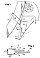
- a holder 40 which consists of a one-piece plastic part is formed, the left and one right holding plate 42 and 44 and left and right Guide element 46 and 48 has. Both holding plates 42 and 44 are provided with a cutout 50, around which transversely extending shoulder 36 of the protector 34. Like it in Figure 4 is shown, the holding plates 42 and 44 are inward biased to clamp more firmly on guard 34. So could it also behaves with the guide elements 46, 48.
- the present holder 40 of the seed tube 20 consists of a simple part that is usually made of plastic Seed tube 20 holds on the center line of the seed furrow. On this way, seeds are deposited in a better aligned manner, and that Seed tube 20 is before wear on the discs of the Furrow opener 22 protected.
Description
- Fig. 1
- eine Pflanzeinheit mit einem Saatgutrohr und einem Halter in Seitenansicht,
- Fig. 2
- den Halter in einer vergrößerten Darstellung in Seitenansicht,
- Fig. 3
- einen Schnitt entlang der Linie 3-3 in Figur 2 und in Blickrichtung der dazugehörigen Pfeile und
- Fig. 4
- den Halter in Draufsicht.
Claims (8)
- Furchenöffner (22) mit mehreren von einem Rahmen (33) getragenen Scharen, die zwischen sich ein Saatgutrohr (20) aufnehmen, und mit einem Halter (40), der:a) einstückig ausgebildet ist undb) mit Abstand zwischen den Scharen angeordnet ist.
dadurch gekennzeichnet, daß der Halter (40)c) einerseits Halteplatten (42, 44) zur Festlegung an dem Rahmen (33) undd) andererseits Führungselemente (46, 48) zur Erfassung des Saatgutrohrs (20) aufweist. - Furchenöffner (22) nach Anspruch 1, dadurch gekennzeichnet, daß in dem Bereich zwischen den Scharen und in Fahrtrichtung vor dem Saatgutrohr (20) an dem Rahmen (33) ein insbesondere starrer Schutz (34) vorgesehen ist, an dem der Halter (40) angreift.
- Furchenöffner nach Anspruch 1 oder 2, dadurch gekennzeichnet, daß der Halter (40) mit wenigstens einem Ausschnitt (50) versehen ist, der der Übergreifung des Rahmens (33) bzw. des Schutzes (34) dient.
- Furchenöffner nach einem oder mehreren der vorherigen Ansprüche, dadurch gekennzeichnet, daß der Halter (40) aus Kunststoff gebildet ist.
- Furchenöffner nach einem oder mehreren der vorherigen Ansprüche, dadurch gekennzeichnet, daß die Halteplatten (42, 44) und/oder die Führungselemente (46, 48) unter Vorspannung an dem Rahmen (33) und/oder dem Schutz (34) bzw. dem Saatgutrohr (20) angreifen.
- Furchenöffner nach einem oder mehreren der vorherigen Ansprüche, dadurch gekennzeichnet, daß der Schutz (34) eine sich seitwärts erstreckende Schulter (36) aufweist, die der Aufnahme des Halters (40) dient, wobei dieser insbesondere in seinem Ausschnitt (50) die Schulter (36) aufnimmt.
- Pflanzeinheit 10 mit einem Furchenöffner (22) nach einem oder mehreren der vorherigen Ansprüche, dadurch gekennzeichnet, daß die Schare zueinander schräg verlaufend und drehbar angebracht sind und das Saatgutrohr (20) von einem Dosiergerät (18) ausgeht.
- Pflanzeinheit nach Anspruch 7, dadurch gekennzeichnet, daß dem Furchenöffner (22) ein Scheibensech (32) vor- und Andrückräder (26) nachgeschaltet sind.
Applications Claiming Priority (2)
| Application Number | Priority Date | Filing Date | Title |
|---|---|---|---|
| US659054 | 1996-06-03 | ||
| US08/659,054 US5664507A (en) | 1996-06-03 | 1996-06-03 | Seed tube guide |
Publications (2)
| Publication Number | Publication Date |
|---|---|
| EP0811311A1 EP0811311A1 (de) | 1997-12-10 |
| EP0811311B1 true EP0811311B1 (de) | 2001-09-12 |
Family
ID=24643843
Family Applications (1)
| Application Number | Title | Priority Date | Filing Date |
|---|---|---|---|
| EP97108739A Expired - Lifetime EP0811311B1 (de) | 1996-06-03 | 1997-06-02 | Furchenöffner und Pflanzeinheit mit einem Furchenöffner |
Country Status (7)
| Country | Link |
|---|---|
| US (1) | US5664507A (de) |
| EP (1) | EP0811311B1 (de) |
| AR (1) | AR006795A1 (de) |
| BR (1) | BR9703425A (de) |
| CA (1) | CA2200618C (de) |
| DE (1) | DE59704575D1 (de) |
| ES (1) | ES2160281T3 (de) |
Families Citing this family (18)
| Publication number | Priority date | Publication date | Assignee | Title |
|---|---|---|---|---|
| US6332413B1 (en) | 1995-12-29 | 2001-12-25 | Case Corporation | Seed tube for seed metering apparatus |
| US5826524A (en) * | 1996-10-16 | 1998-10-27 | Deere & Company | Seed forming wheel support having a lockup link |
| US5787994A (en) * | 1996-12-02 | 1998-08-04 | Acra Products, L.L.C. | Narrow profile soil opening device for agriculture material placement |
| US5931105A (en) * | 1998-12-04 | 1999-08-03 | Deere & Company | Sensor plugs for a seed tube |
| US6386127B1 (en) | 2000-02-07 | 2002-05-14 | Case Corporation | Disc opener assembly for a seed planter |
| FR2836003B1 (fr) * | 2002-02-20 | 2004-07-30 | Kuhn Nodet Sa | Dispositif d'implantation de graines dans le sol pour semoir |
| US7263937B2 (en) | 2004-01-31 | 2007-09-04 | Deere & Company | Seed tube guard |
| US7131384B2 (en) * | 2004-08-12 | 2006-11-07 | Kester Philip C | Seed tube guard assembly for agricultural planters |
| WO2007024624A2 (en) * | 2005-08-19 | 2007-03-01 | Precision Planting, Inc. | Wear resistant seed tube for agricultural planter |
| US8499703B2 (en) | 2010-12-08 | 2013-08-06 | Matthew P. Hagny | Seed tube mounting assembly for agricultural seeder |
| US9374942B2 (en) | 2011-03-23 | 2016-06-28 | Schaffert Manufacturing Company, Inc. | Seeding follower isolation device |
| US8978564B2 (en) | 2012-12-12 | 2015-03-17 | Matthew P. Hagny | Seed tube guard with integral fluid channel for agricultural planters |
| DE102016204433B4 (de) | 2016-03-17 | 2023-12-28 | Horsch Maschinen Gmbh | Reiheneinheit einer landwirtschaftlichen Maschine |
| US11032966B2 (en) | 2016-11-03 | 2021-06-15 | Agco Corporation | Audible alarm for seed tube guard wear |
| US11277961B2 (en) | 2018-02-09 | 2022-03-22 | Ag Leader Technology | Seed spacing device for an agricultural planter and related systems and methods |
| US11523554B2 (en) | 2019-01-25 | 2022-12-13 | Ag Leader Technology | Dual seed meter and related systems and methods |
| US11785881B2 (en) | 2019-08-19 | 2023-10-17 | Ag Leader Technology | Adjustable seed meter and related systems and methods |
| US11877530B2 (en) | 2019-10-01 | 2024-01-23 | Ag Leader Technology | Agricultural vacuum and electrical generator devices, systems, and methods |
Family Cites Families (13)
| Publication number | Priority date | Publication date | Assignee | Title |
|---|---|---|---|---|
| US2724159A (en) * | 1951-04-06 | 1955-11-22 | Louis H Morin | Gooseneck construction of die casting machine |
| FR1235304A (fr) * | 1955-02-10 | 1960-07-08 | Massey Harris Ferguson Ltd | Appareil distributeur de semence et d'engrais et machine-semoir munie dudit appareil |
| US3155293A (en) * | 1962-08-03 | 1964-11-03 | Cotter Howard Ernest | Spreader apparatus |
| US3658018A (en) * | 1970-03-23 | 1972-04-25 | Int Harvester Co | Self centering seed shoe for double disk furrow opener |
| US4224882A (en) * | 1978-02-21 | 1980-09-30 | Cruse John W | Apparatus for sowing seeds in suspension |
| US4388878A (en) * | 1981-10-19 | 1983-06-21 | Demzin Fred W | Multiple deposition type seeder foot assembly |
| US4520742A (en) * | 1983-08-11 | 1985-06-04 | Steven Anderson | Seed planter attachment for chisel plow |
| US4915258A (en) * | 1985-02-28 | 1990-04-10 | Deere & Company | Seed meter seed tube |
| GB8520043D0 (en) * | 1985-08-09 | 1985-09-18 | Clantex Ltd | Flowable compositions |
| CA1268379A (en) * | 1988-10-21 | 1990-05-01 | Froc Enterprises Ltd. | Air seeder boot |
| US5092255A (en) * | 1991-01-22 | 1992-03-03 | Deere & Company | Seed boot extension |
| US5271343A (en) * | 1992-04-06 | 1993-12-21 | House John L | Planter insecticide tube alignment bracket |
| US5622124A (en) * | 1996-02-12 | 1997-04-22 | Unverferth Manufacturing Co., Inc. | Coulter fertilizer tine |
-
1996
- 1996-06-03 US US08/659,054 patent/US5664507A/en not_active Expired - Fee Related
-
1997
- 1997-03-20 CA CA002200618A patent/CA2200618C/en not_active Expired - Fee Related
- 1997-04-22 AR ARP970101632A patent/AR006795A1/es unknown
- 1997-06-02 EP EP97108739A patent/EP0811311B1/de not_active Expired - Lifetime
- 1997-06-02 BR BR9703425A patent/BR9703425A/pt not_active IP Right Cessation
- 1997-06-02 DE DE59704575T patent/DE59704575D1/de not_active Expired - Fee Related
- 1997-06-02 ES ES97108739T patent/ES2160281T3/es not_active Expired - Lifetime
Also Published As
| Publication number | Publication date |
|---|---|
| US5664507A (en) | 1997-09-09 |
| DE59704575D1 (de) | 2001-10-18 |
| EP0811311A1 (de) | 1997-12-10 |
| CA2200618C (en) | 2000-05-30 |
| CA2200618A1 (en) | 1997-12-03 |
| AR006795A1 (es) | 1999-09-29 |
| ES2160281T3 (es) | 2001-11-01 |
| BR9703425A (pt) | 1998-09-15 |
| MX9703008A (es) | 1998-05-31 |
Similar Documents
| Publication | Publication Date | Title |
|---|---|---|
| EP0811311B1 (de) | Furchenöffner und Pflanzeinheit mit einem Furchenöffner | |
| EP1051896B1 (de) | Säschar | |
| EP0049330B1 (de) | Verfahren zum Ausbringen von Saatgut, Herrichten eines Saatbettes und Gerätekombination zur Verfahrensdurchführung | |
| EP1587355A1 (de) | Saatgutführung | |
| DE2552810B2 (de) | Maschine zum Ausbringen von Saatgut und Düngemitteln | |
| DE4237093A1 (de) | Direktsämaschine für das Direktsaatverfahren | |
| DE102010017631A1 (de) | Landwirtschaftliche Bestellkombination | |
| DE3644767C2 (de) | ||
| DE2839601C2 (de) | ||
| WO2003001896A2 (de) | Direktsämaschine | |
| EP0193804B1 (de) | Verfahren für die Aussaat von Nutzpflanzensaatgut | |
| EP0803176A1 (de) | Vorrichtung zum Einstellen von wenigstens einem Andrückrad und Reihenpflanzeinheit mit einer solchen Vorrichtung | |
| EP2240007B1 (de) | Sämaschine | |
| DE1904273A1 (de) | Einzelkornsaemaschine | |
| WO2019030309A1 (de) | Säschar sowie sämaschine | |
| DE2001062A1 (de) | Drillmaschine | |
| DE3143408C2 (de) | ||
| EP1478220B1 (de) | Tiefenführungs- und druckrollen für sämaschine | |
| DE2842294C2 (de) | ||
| WO2008061621A1 (de) | Sämaschine | |
| DE3929204A1 (de) | Grubber | |
| EP0214369B1 (de) | Gerätekombination zum Ausbringen von Saatgut | |
| DE102006023053A1 (de) | Sämaschine | |
| DE102005042459A1 (de) | Sämaschine | |
| AT288751B (de) | Sae- und duengerstreumaschine |
Legal Events
| Date | Code | Title | Description |
|---|---|---|---|
| PUAI | Public reference made under article 153(3) epc to a published international application that has entered the european phase |
Free format text: ORIGINAL CODE: 0009012 |
|
| AK | Designated contracting states |
Kind code of ref document: A1 Designated state(s): DE ES FR IT |
|
| 17P | Request for examination filed |
Effective date: 19980428 |
|
| AKX | Designation fees paid |
Free format text: DE ES FR IT |
|
| RBV | Designated contracting states (corrected) |
Designated state(s): DE ES FR IT |
|
| 17Q | First examination report despatched |
Effective date: 20000113 |
|
| GRAG | Despatch of communication of intention to grant |
Free format text: ORIGINAL CODE: EPIDOS AGRA |
|
| GRAG | Despatch of communication of intention to grant |
Free format text: ORIGINAL CODE: EPIDOS AGRA |
|
| GRAH | Despatch of communication of intention to grant a patent |
Free format text: ORIGINAL CODE: EPIDOS IGRA |
|
| RAP1 | Party data changed (applicant data changed or rights of an application transferred) |
Owner name: DEERE & COMPANY |
|
| GRAH | Despatch of communication of intention to grant a patent |
Free format text: ORIGINAL CODE: EPIDOS IGRA |
|
| GRAA | (expected) grant |
Free format text: ORIGINAL CODE: 0009210 |
|
| AK | Designated contracting states |
Kind code of ref document: B1 Designated state(s): DE ES FR IT |
|
| REF | Corresponds to: |
Ref document number: 59704575 Country of ref document: DE Date of ref document: 20011018 |
|
| REG | Reference to a national code |
Ref country code: ES Ref legal event code: FG2A Ref document number: 2160281 Country of ref document: ES Kind code of ref document: T3 |
|
| ET | Fr: translation filed | ||
| PLBE | No opposition filed within time limit |
Free format text: ORIGINAL CODE: 0009261 |
|
| STAA | Information on the status of an ep patent application or granted ep patent |
Free format text: STATUS: NO OPPOSITION FILED WITHIN TIME LIMIT |
|
| 26N | No opposition filed | ||
| PGFP | Annual fee paid to national office [announced via postgrant information from national office to epo] |
Ref country code: FR Payment date: 20050617 Year of fee payment: 9 |
|
| PGFP | Annual fee paid to national office [announced via postgrant information from national office to epo] |
Ref country code: DE Payment date: 20050630 Year of fee payment: 9 |
|
| PGFP | Annual fee paid to national office [announced via postgrant information from national office to epo] |
Ref country code: ES Payment date: 20050708 Year of fee payment: 9 |
|
| PG25 | Lapsed in a contracting state [announced via postgrant information from national office to epo] |
Ref country code: ES Free format text: LAPSE BECAUSE OF NON-PAYMENT OF DUE FEES Effective date: 20060603 |
|
| PGFP | Annual fee paid to national office [announced via postgrant information from national office to epo] |
Ref country code: IT Payment date: 20060630 Year of fee payment: 10 |
|
| PG25 | Lapsed in a contracting state [announced via postgrant information from national office to epo] |
Ref country code: DE Free format text: LAPSE BECAUSE OF NON-PAYMENT OF DUE FEES Effective date: 20070103 |
|
| REG | Reference to a national code |
Ref country code: FR Ref legal event code: ST Effective date: 20070228 |
|
| REG | Reference to a national code |
Ref country code: ES Ref legal event code: FD2A Effective date: 20060603 |
|
| PG25 | Lapsed in a contracting state [announced via postgrant information from national office to epo] |
Ref country code: FR Free format text: LAPSE BECAUSE OF NON-PAYMENT OF DUE FEES Effective date: 20060630 |
|
| PG25 | Lapsed in a contracting state [announced via postgrant information from national office to epo] |
Ref country code: IT Free format text: LAPSE BECAUSE OF NON-PAYMENT OF DUE FEES Effective date: 20070602 |