EP0811397A2 - Implantable unit - Google Patents
Implantable unit Download PDFInfo
- Publication number
- EP0811397A2 EP0811397A2 EP97109044A EP97109044A EP0811397A2 EP 0811397 A2 EP0811397 A2 EP 0811397A2 EP 97109044 A EP97109044 A EP 97109044A EP 97109044 A EP97109044 A EP 97109044A EP 0811397 A2 EP0811397 A2 EP 0811397A2
- Authority
- EP
- European Patent Office
- Prior art keywords
- contact
- housing
- unit according
- implantable unit
- contacts
- Prior art date
- Legal status (The legal status is an assumption and is not a legal conclusion. Google has not performed a legal analysis and makes no representation as to the accuracy of the status listed.)
- Granted
Links
- 238000007789 sealing Methods 0.000 claims abstract description 41
- 230000007246 mechanism Effects 0.000 claims abstract description 14
- 229920001296 polysiloxane Polymers 0.000 claims description 5
- 238000003780 insertion Methods 0.000 claims description 2
- 230000037431 insertion Effects 0.000 claims description 2
- 239000013013 elastic material Substances 0.000 description 12
- POIUWJQBRNEFGX-XAMSXPGMSA-N cathelicidin Chemical compound C([C@@H](C(=O)N[C@@H](CCCNC(N)=N)C(=O)N[C@@H](CCCCN)C(=O)N[C@@H](CO)C(=O)N[C@@H](CCCCN)C(=O)N[C@@H](CCC(O)=O)C(=O)N[C@@H](CCCCN)C(=O)N[C@@H]([C@@H](C)CC)C(=O)NCC(=O)N[C@@H](CCCCN)C(=O)N[C@@H](CCC(O)=O)C(=O)N[C@@H](CC=1C=CC=CC=1)C(=O)N[C@@H](CCCCN)C(=O)N[C@@H](CCCNC(N)=N)C(=O)N[C@@H]([C@@H](C)CC)C(=O)N[C@@H](C(C)C)C(=O)N[C@@H](CCC(N)=O)C(=O)N[C@@H](CCCNC(N)=N)C(=O)N[C@@H]([C@@H](C)CC)C(=O)N[C@@H](CCCCN)C(=O)N[C@@H](CC(O)=O)C(=O)N[C@@H](CC=1C=CC=CC=1)C(=O)N[C@@H](CC(C)C)C(=O)N[C@@H](CCCNC(N)=N)C(=O)N[C@@H](CC(N)=O)C(=O)N[C@@H](CC(C)C)C(=O)N[C@@H](C(C)C)C(=O)N1[C@@H](CCC1)C(=O)N[C@@H](CCCNC(N)=N)C(=O)N[C@@H]([C@@H](C)O)C(=O)N[C@@H](CCC(O)=O)C(=O)N[C@@H](CO)C(O)=O)NC(=O)[C@H](CC=1C=CC=CC=1)NC(=O)[C@H](CC(O)=O)NC(=O)CNC(=O)[C@H](CC(C)C)NC(=O)[C@@H](N)CC(C)C)C1=CC=CC=C1 POIUWJQBRNEFGX-XAMSXPGMSA-N 0.000 description 9
- 238000002513 implantation Methods 0.000 description 6
- 238000000034 method Methods 0.000 description 5
- 230000008569 process Effects 0.000 description 5
- 210000001124 body fluid Anatomy 0.000 description 4
- 239000010839 body fluid Substances 0.000 description 4
- 230000000694 effects Effects 0.000 description 4
- 238000009413 insulation Methods 0.000 description 4
- 239000012212 insulator Substances 0.000 description 4
- 239000007943 implant Substances 0.000 description 3
- 230000009471 action Effects 0.000 description 2
- 210000000988 bone and bone Anatomy 0.000 description 2
- 238000013461 design Methods 0.000 description 2
- 239000007769 metal material Substances 0.000 description 2
- 230000000149 penetrating effect Effects 0.000 description 2
- 239000000758 substrate Substances 0.000 description 2
- 240000003517 Elaeocarpus dentatus Species 0.000 description 1
- 240000005561 Musa balbisiana Species 0.000 description 1
- 235000018290 Musa x paradisiaca Nutrition 0.000 description 1
- 239000000853 adhesive Substances 0.000 description 1
- 230000001070 adhesive effect Effects 0.000 description 1
- 238000004873 anchoring Methods 0.000 description 1
- 238000005452 bending Methods 0.000 description 1
- 230000015572 biosynthetic process Effects 0.000 description 1
- 239000000919 ceramic Substances 0.000 description 1
- 230000008878 coupling Effects 0.000 description 1
- 238000010168 coupling process Methods 0.000 description 1
- 238000005859 coupling reaction Methods 0.000 description 1
- 239000003814 drug Substances 0.000 description 1
- 229940079593 drug Drugs 0.000 description 1
- 239000012777 electrically insulating material Substances 0.000 description 1
- 230000006870 function Effects 0.000 description 1
- 239000002655 kraft paper Substances 0.000 description 1
- 239000000463 material Substances 0.000 description 1
- 239000002184 metal Substances 0.000 description 1
- 229920000515 polycarbonate Polymers 0.000 description 1
- 239000004417 polycarbonate Substances 0.000 description 1
- 238000012545 processing Methods 0.000 description 1
- 230000001953 sensory effect Effects 0.000 description 1
- 230000008054 signal transmission Effects 0.000 description 1
- 210000003625 skull Anatomy 0.000 description 1
- 238000012360 testing method Methods 0.000 description 1
- 230000009466 transformation Effects 0.000 description 1
Images

Classifications
-
- A—HUMAN NECESSITIES
- A61—MEDICAL OR VETERINARY SCIENCE; HYGIENE
- A61N—ELECTROTHERAPY; MAGNETOTHERAPY; RADIATION THERAPY; ULTRASOUND THERAPY
- A61N1/00—Electrotherapy; Circuits therefor
- A61N1/18—Applying electric currents by contact electrodes
- A61N1/32—Applying electric currents by contact electrodes alternating or intermittent currents
- A61N1/36—Applying electric currents by contact electrodes alternating or intermittent currents for stimulation
- A61N1/372—Arrangements in connection with the implantation of stimulators
- A61N1/375—Constructional arrangements, e.g. casings
- A61N1/3752—Details of casing-lead connections
- A61N1/3754—Feedthroughs
-
- H—ELECTRICITY
- H01—ELECTRIC ELEMENTS
- H01R—ELECTRICALLY-CONDUCTIVE CONNECTIONS; STRUCTURAL ASSOCIATIONS OF A PLURALITY OF MUTUALLY-INSULATED ELECTRICAL CONNECTING ELEMENTS; COUPLING DEVICES; CURRENT COLLECTORS
- H01R13/00—Details of coupling devices of the kinds covered by groups H01R12/70 or H01R24/00 - H01R33/00
- H01R13/46—Bases; Cases
- H01R13/52—Dustproof, splashproof, drip-proof, waterproof, or flameproof cases
- H01R13/5219—Sealing means between coupling parts, e.g. interfacial seal
-
- H—ELECTRICITY
- H01—ELECTRIC ELEMENTS
- H01R—ELECTRICALLY-CONDUCTIVE CONNECTIONS; STRUCTURAL ASSOCIATIONS OF A PLURALITY OF MUTUALLY-INSULATED ELECTRICAL CONNECTING ELEMENTS; COUPLING DEVICES; CURRENT COLLECTORS
- H01R13/00—Details of coupling devices of the kinds covered by groups H01R12/70 or H01R24/00 - H01R33/00
- H01R13/02—Contact members
- H01R13/22—Contacts for co-operating by abutting
- H01R13/24—Contacts for co-operating by abutting resilient; resiliently-mounted
-
- H—ELECTRICITY
- H01—ELECTRIC ELEMENTS
- H01R—ELECTRICALLY-CONDUCTIVE CONNECTIONS; STRUCTURAL ASSOCIATIONS OF A PLURALITY OF MUTUALLY-INSULATED ELECTRICAL CONNECTING ELEMENTS; COUPLING DEVICES; CURRENT COLLECTORS
- H01R2201/00—Connectors or connections adapted for particular applications
- H01R2201/12—Connectors or connections adapted for particular applications for medicine and surgery
Definitions
- the invention relates to an implantable unit with at least one contact arrangement for connecting an electrical or electronic device hermetically sealed in a housing with at least one connection cable led out of the housing.
- the invention is concerned with a releasable electrical connection between an implant housing which houses active electronic components and sensors or actuators which are to be placed at a very specific location in the body and are operated by the active electronic components.
- Such implantable connectors are used in pacemakers, defibrillators and cardioverters.
- the sensors and actuators which are expensive to implant and operate, are left on site as far as possible. This has led to a standard for pacemakers, so that different models can be connected to the sensors and actuators once they have been placed.
- Requirements for the electrode plug and the plug socket are specified in DIN VDE 0750 Part 91, which also includes a precise specification of the dimensions and tolerances. Plugs designed in accordance with this DIN standard function similarly to a banana plug, but have two contact surfaces with different diameters, which are separated from one another by sealing O-rings (sealing lips).
- the connector receptacle is also dimensionally determined in accordance with the connector in this DIN standard.
- the diameter of the sealing lips and the connector receptacle determine the contact pressure and the sealing effect that can be achieved against penetrating body fluid.
- the standard also includes a test specification regarding the insulation impedance, which must be greater than 50 k ⁇ .
- EP-A-0 587 379 and EP-A-0 306 443 relate to a coaxial embodiment of the connector system described.
- EP-A-0 339 877 provides for contacting the cylindrical plug by using conductive silicone in the plug receptacle.
- conductive silicone in the plug receptacle.
- several contacts can be realized on the cylindrical connector. Since both the contacts and the insulators are flexible, the formation of sealing lips can be dispensed with, by adjusting the diameter of the plug receptacle and pin to achieve a corresponding contact pressure both in the contact zone and in the insulating zone.
- the contact pressure is limited by the glide path that must be manageably traversed when inserting the connector.
- German laid-open specification DE-A-33 31 620 deviates from the cylindrical connector, which can contain a plurality of contact surfaces which are isolated from one another by sealing lips, and provides a plurality of contact pins which protrude vertically from a connector base plate.
- O-rings placed around the contacts provide a seal when the connector base plate is screwed against the housing.
- a significantly higher contact pressure can be achieved by using the screws to produce the sealing effect, since this pressure does not have to be overcome when the plug is inserted manually.
- EP-A-0 001 897 describes the electrical connection option between two substrates using alternating layers of non-conductive and conductive silicones. It is assumed that the substrates are located directly in the body medium.
- Implants of the type mentioned at the outset should take up as little space as possible when implanted in the body and should therefore be largely miniaturized. If the plug connections known from the prior art are also miniaturized in the course of such miniaturization, plug connections are obtained with very thin, elongated contacts which can easily be broken off, bent or otherwise damaged when inserted into corresponding sockets.
- the contact arrangement has a first contact, a second contact mounted on an elastic body, a locking mechanism for engaging the end face of the first contact with the end face of the second contact and has at least one sealing web surrounding the first contact, which is pressed into the elastic body when the contacts engage and seals the contacts to the outside.
- a plurality of sealing webs which are concentric with one another can be provided, it being possible for at least one sealing web assigned to this contact arrangement to be provided for each contact arrangement when using a plurality of contact arrangements.
- the first contact is fixed to the housing and connected to the electrical or electronic device accommodated in the housing, while the second contact is connected to the connecting cable, the first contact can be formed directly by a housing bushing of the electrical or electronic device, in which case an electrically insulating molded body is preferably provided, which surrounds the housing bushing.
- the closure mechanism has a closure cap connected to the at least one connection cable, in which at least a first contact and / or at least a second contact is arranged, an engagement arrangement being provided in order to hold the closure cap in engagement with the housing.
- the sealing cap with the contacts located therein forms a unit, e.g. can be attached to the housing via a thread assigned to the housing and a screw assigned to the closure cap.
- a snap connection acting between the closure cap and the housing can be provided.
- the connecting cable is provided with a connecting piece which carries one or more first or second contacts, and who the locking mechanism has a sealing cap with a receptacle for the connecting piece.
- the possibility of exchanging the connecting cable is particularly advantageous when several connecting cables are to be connected to the device accommodated in the housing.
- a screw and an associated thread or a locking connection serve to hold the closure cap in engagement with the housing.
- the arrangement is preferably such that a defined torque, which is applied to the screw, is required for contact between the first and second contacts.
- a suitable tool in particular a torque wrench, excessive stress on both the screw and the components that come into contact with one another is thus avoided, and the operator can nevertheless be certain that the desired contacts are being made. Furthermore, the closing force can thus be safely introduced even with a large number of seals and contacts to be closed.
- connection pieces are introduced in a direction perpendicular to the connecting cables and the force for connecting the contacts can be applied in a direction perpendicular to the direction of action of this force.
- a connection piece can be provided on the at least one connection cable and the housing has a trough-shaped extension for receiving the at least one connection piece, with a wedge for insertion between the wall side of the trough-shaped extension and the one located away from the housing in the trough-shaped extension inserted connector is provided.
- the wedge Inserted and fixed by means of a specially provided screw he presses the connector against the housing in a direction perpendicular to the screw axis.
- This displacement-force transformation means that the locking mechanism can also be used with a housing that is implanted parallel to the patient's skin, e.g. a housing embedded in the skull bone, operable from above, so that the housing does not come out of its fixed anchoring, e.g. a bone bed, must be removed.
- a housing that is implanted parallel to the patient's skin, e.g. a housing embedded in the skull bone, operable from above, so that the housing does not come out of its fixed anchoring, e.g. a bone bed, must be removed.
- the treating surgeon has both hands free for the connection process and does not have to hold the housing for the connection process as in conventional arrangements.
- the risk of pulling on the cables connected to the actuator or sensor system during connection which can damage the very thin cables (especially in multi-channel systems) or the sensors and actuators, is thus considerably reduced .
- connection process must first be completed before being placed in the final implantation site, also require a certain length of excess cable for the connection process, which is looped around the housing at the implantation site.
- the coupling principle proposed here enables direct and short conduction paths between the device accommodated in the housing and the sensor or actuator components to be connected to it.
- a locking device can also be provided between the wedge and the housing, so that the wedge can be inserted manually and a tool for operating the screw can be dispensed with.
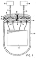
- FIG. 1 shows a section through an implantable unit with a housing 10 for receiving an electrical or electronic device 11 indicated as a block, for example the signal converter of an implantable hearing device, the signal processing electronics of a pacemaker etc.
- the connection of the device accommodated in the hermetically sealed housing 10 also with actuator or sensor components 13, 15, shown only as a block, are made via connecting cables 12, 14, the ends of which are embedded in connecting pieces 16, which are inserted into an end cap 18 provided on the end face of the housing 10 during implantation of the unit.
- a screw connection is used to fix the connecting pieces 16, which is formed by a thread 19 assigned to the housing 10 and a screw 20 assigned to the closure cap 18.
- FIG. 1 shows an embodiment for an implantable unit with a sensor and an actuator element 13 or 15, which are to be arranged spatially separate from one another, and which therefore require their own connection cables. It goes without saying, however, that the principle described below can be implemented in the same way in embodiments with only one or with more than two connecting cables. If the sensor and actuator channels lead to different implantation locations, then a connection cable should exist for each implantation location, the connector of which can be disconnected independently of the others, so that a fault in the sensors or actuators does not require a complete renewed operation (RE-OP).
- RE-OP complete renewed operation
- bushings 22 with a flat front side are provided on the front side of the housing, which are separated by an insulator 24, such as ceramic, from the body of the housing, which is usually made of metal, and are held rigidly.
- the insulator 24 also provides a hermetic seal between the bushings 22 and the housing 10.
- Sealing webs 28 are provided which, when the housing 10 and the end cap 18 are screwed together, dig into the connecting pieces 16 made of an elastic material.
- two circular sealing webs 28 are provided for each of the bushings 22, which concentrically surround the respective bushing.
- sealing webs can also be provided which enclose a plurality of contacts, for example the contacts assigned to a connecting piece or all contacts of the entire unit.
- the dimensions of the molded body 26, the connecting pieces 16 and the end cap 18 are chosen so that the elastic material of the connecting pieces 16, which is preferably silicone, is not stressed beyond its elastic limit when the end cap 18 is screwed on, so that a restoring force is maintained which generates a high pressure on the sealing webs and which is shown in FIG. 5 is referred to as sealing force F D.
- sealing force F D a contact force generated between the bushings 22 and the cap-side contacts 30, which are embedded in the elastic material of the connecting pieces 16, in that the contacts 30 upon contact with the non-retracting contact surfaces of the bushings 22 be pushed into the elastic material of the connecting pieces 16, which maintains this contact force like a spring.
- the contact force F K is preferably chosen so large that the surfaces of the metallic contacts begin to flow and ensure a gas-tight closure of the contact point.
- one of the two mutually engaging contacts is designed with a rounded end face in order not to have to maintain unnecessarily high accuracy with respect to the plane parallelism in the case of multiple contacts.
- the required contact force depends on the metallic material and the required contact area (current carrying capacity). The limit of elasticity of the elastic material for a given contact surface of the contact, which must be considerably larger than the actual contact surface, is limiting.
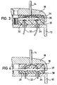
- FIG. 3 shows a section of a housing 10 and an end cap 18, in which case an elastic body 32 is applied to the end face of the housing 10, for example by means of adhesive, in which two contacts 30 with an approximately hemispherically rounded end surface are embedded.
- the contacts 30 are connected to the electrical or electronic device accommodated within the housing 10 via connecting wires 33 which are shielded from the housing 10 by means of insulators 24.
- a rigid connecting piece 34 is applied to the end of the connecting cable 14, which is analogous to that in FIGS. 1 and 2 Shown body 26 is provided with sealing webs and in which two disc-shaped contacts 36 with a flat end face are embedded opposite the contacts 30.
- the connecting pieces are preferably coded or they differ in shape and / or size.
- Another way of coding is that one of the two connection cables, e.g. the cable leading to an actuator, with a connector according to FIG. 1, while for the other connecting cable, e.g. the cable leading to a sensor, a connector according to FIG. 3 is provided.
- the end face of the housing 10 is then correspondingly provided with a molded body 26 and an elastic body 32 for the respective connecting pieces.
- the end cap can also be permanently connected with one or more connecting pieces and cables. In this case, however, since the replacement e.g. If only one of the connection cables were possible, such an embodiment is less preferred.
- FIG. 4 is a section similar to FIG. 3 shows a further modified embodiment of the implantable unit, in which the engagement between the housing and the closure cap takes place via a snap connection instead of via a screw connection.
- the end cap 18 has on the inside of its edge facing the housing 10 one or more locking projections 37 which snap into corresponding recesses 38 associated with the housing when the housing and end cap are joined together.
- the recess 38 is formed by a protruding edge of the molded body 26 applied to the side of the housing 10 containing the bushings 22. It is understood that a functionally analogous locking connection between the end cap and the housing can be achieved independently of the shape of the molded body 26 by appropriate design of the end cap 18 and the housing 10 itself.
- one or more further recesses can be provided parallel to the recess 38, or the component engaging with the latching projection can have a sawtooth-like surface.
- the locking mechanism must press the connecting pieces against the housing with a defined locking force, so that a gas-tight contact lock is created and the sealing effect is guaranteed.
- the connecting pieces Before the force acts on the elastic material, which produces a spring-like restoring force via the deformation path s , the connecting pieces must be in the exactly correct position.
- a simple solution is to insert the connectors into the end cap, which is pulled to the housing with a screw with a defined torque. However, this process is only possible to a limited extent if the housing is already anchored in a bone bed because the closure takes place from the front.
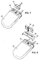
- FIGS. 7 and 8 illustrate a modified embodiment of the housing 40 shown in perspective on the front of a type of trough 42, into which connection pieces 44 are introduced from above. These connecting pieces are brought into the exact position by means of a cover 46 to be placed in the area of the tub 42 and then pressed against the housing 40 by a defined deformation path by means of a wedge 48.
- the circumferential contour of the connecting pieces 44 and the corresponding receptacle in the trough 42 can be designed in the manner mentioned above in such a way that no connecting piece fits into the receptacle of the other.
- FIG. 7 shows a connector 44 which is designed for a four-pole connection.
- the cover 46 is placed after inserting the connectors 44 into the tub 42.
- a wedge 48 is inserted between the connecting pieces 44 and the wall side 51 of the tub 42 remote from the housing 40, so that the connecting pieces 44 move by the defined deformation path in the direction of the wall surface 54 of the housing having the contacts 40 pushed and pressed against them.
- the wedge 48 can be inserted and fixed with the aid of a screw 52, or a locking mechanism (not shown) can be provided, by means of which the manually inserted wedge 48 is fixed in the installed position.
- connection principle described above between a device to be implanted and actuator and / or sensory components allows an insulation impedance between the individual contacts of more than 50 M ⁇ , this value multiplying the insulation impedance of 50 k ⁇ required by the aforementioned DIN standard for pacemakers by a multiple exceeds.
- an implantable hearing aid requires gains of> 80 dB between the sensor and the actuator without feedback between the sensor signals and the actuator signals, and analog signals in the ⁇ V range should be able to be transmitted without distortion via the contact arrangement.
- the proposed implantable unit thus makes it possible to satisfy the high demands on the type of contact which apply to implantable hearing aids and which correspond to the requirements of signal transmission in the audio and hi-fi field.
- the contact arrangements can be closed easily, safely and reliably. Without the use of the typical male and female design of the contacts in the form of a pin and an associated socket, there is no risk in the proposed systems that the contacts can be broken, bent or otherwise damaged.
Abstract
Description
Die Erfindung bezieht sich auf eine implantierbare Einheit mit mindestens einer Kontaktanordnung zur Verbindung einer in einem Gehäuse hermetisch dicht untergebrachten elektrischen oder elektronischen Vorrichtung mit mindestens einem aus dem Gehäuse herausgeführten Anschlußkabel. Insbesondere befaßt sich die Erfindung mit einer lösbaren elektrischen Verbindung zwischen einem Implantatgehäuse, das aktive elektronische Komponenten beherbergt, und Sensoren oder Aktoren, die an einen ganz gezielten Ort im Körper zu plazieren sind und von den aktiven elektronischen Komponenten betrieben werden.The invention relates to an implantable unit with at least one contact arrangement for connecting an electrical or electronic device hermetically sealed in a housing with at least one connection cable led out of the housing. In particular, the invention is concerned with a releasable electrical connection between an implant housing which houses active electronic components and sensors or actuators which are to be placed at a very specific location in the body and are operated by the active electronic components.
Derartige implantierbare Steckverbindungen werden bei Herzschrittmachern, Defibrillatoren und Kardiovertern eingesetzt. Beim Austausch der implantierten Elektronik, die auf Grund der verbrauchten Energiequelle erforderlich wird, wird die operationstechnisch aufwendig zu ex- und implantierende Sensorik und Aktorik nach Möglichkeit vor Ort belassen. Dies hat bei Herzschrittmachern zu einem Standard geführt, so daß unterschiedliche Modelle an die einmal gelegte Sensorik und Aktorik angeschlossen werden können. Anforderungen an den Elektrodenstecker und die Steckerbuchse sind in der DIN VDE 0750 Teil 91 festgelegt, die auch eine genaue Vorgabe der Maße und Toleranzen beinhaltet. Gemäß dieser DIN-Norm ausgebildete Stecker funktionieren ähnlich wie ein Bananenstecker, verfügen jedoch über zwei Kontaktflächen mit unterschiedlichem Durchmesser, die durch dichtende O-Ringe (Dichtlippen) voneinander getrennt sind. Die Steckeraufnahme ist entsprechend dem Stecker ebenfalls in dieser DIN-Norm maßlich festgelegt. Die Durchmesser der Dichtlippen und der Steckeraufnahme bestimmen den Anpreßdruck und die hiermit erzielbare Dichtwirkung gegen eindringende Körperflüssigkeit. Die Norm beinhaltet weiterhin eine Prüfvorschrift bezüglich der Isolationsimpedanz, die größer als 50 kΩ sein muß.Such implantable connectors are used in pacemakers, defibrillators and cardioverters. When replacing the implanted electronics, which is required due to the energy source used, the sensors and actuators, which are expensive to implant and operate, are left on site as far as possible. This has led to a standard for pacemakers, so that different models can be connected to the sensors and actuators once they have been placed. Requirements for the electrode plug and the plug socket are specified in DIN VDE 0750 Part 91, which also includes a precise specification of the dimensions and tolerances. Plugs designed in accordance with this DIN standard function similarly to a banana plug, but have two contact surfaces with different diameters, which are separated from one another by sealing O-rings (sealing lips). The connector receptacle is also dimensionally determined in accordance with the connector in this DIN standard. The diameter of the sealing lips and the connector receptacle determine the contact pressure and the sealing effect that can be achieved against penetrating body fluid. The standard also includes a test specification regarding the insulation impedance, which must be greater than 50 kΩ.
Zahlreiche Patentschriften befassen sich mit der produktionstechnischen Ausführung der Steckeraufnahme an einem hermetisch dichten Gehäuse, der produktionstechnischen Ausführung des Steckers, der Art der Kontaktgebung und der Fixation des Steckers im Steckergehäuse. Alle der folgenden Patentschriften haben eine zylinderförmige Öffnung zur Aufnahme eines zylindrischen Steckers mit einer oder mehreren Kontaktstellen und isolierenden Dichtlippen gemeinsam:
EP-A-0 052 690, US-A-4 262 673, EP-A-0 006 281, EP-B-0 052 879, EP-A-0 442 807, WO-A-90/02581, WO-A-91/04069, WO-A-91/16947, WO-A-93/05844, WO-A-93/02742, WO-A-89/05170, EP-A-0 357 941.Numerous patents deal with the technical production of the connector receptacle on a hermetically sealed housing, the technical production of the connector, the type of contact and the fixation of the connector in the connector housing. All of the following patents have a cylindrical opening for receiving a cylindrical plug with one or more contact points and insulating sealing lips in common:
EP-A-0 052 690, US-A-4 262 673, EP-A-0 006 281, EP-B-0 052 879, EP-A-0 442 807, WO-A-90/02581, WO- A-91/04069, WO-A-91/16947, WO-A-93/05844, WO-A-93/02742, WO-A-89/05170, EP-A-0 357 941.
EP-A-0 587 379 und EP-A-0 306 443 beziehen sich auf eine koaxiale Ausführungsmöglichkeit des beschriebenen Steckverbindungssystems.EP-A-0 587 379 and EP-A-0 306 443 relate to a coaxial embodiment of the connector system described.
Die Druckschrift EP-A-0 339 877 sieht die Kontaktgebung zum zylindrischen Stecker durch Verwendung von leitfähigem Silikon in der Steckeraufnahme vor. Durch Wechsel von leitfähigen und nicht leitfähigen Schichten können mehrere Kontakte auf dem zylindrischen Stecker realisiert werden. Da sowohl die Kontakte als auch die Isolatoren flexibel sind, kann auf die Ausbildung von Dichtlippen verzichtet werden, indem durch Anpassung der Durchmesser von Steckeraufnahme und Stift ein entsprechender Anpreßdruck sowohl in der Kontaktzone als auch in der isolierenden Zone realisiert wird. Der Anpreßdruck ist durch den Gleitweg limitiert, der beim Einführen der Stecker handhabbar durchfahren werden muß.EP-A-0 339 877 provides for contacting the cylindrical plug by using conductive silicone in the plug receptacle. By changing conductive and non-conductive layers, several contacts can be realized on the cylindrical connector. Since both the contacts and the insulators are flexible, the formation of sealing lips can be dispensed with, by adjusting the diameter of the plug receptacle and pin to achieve a corresponding contact pressure both in the contact zone and in the insulating zone. The contact pressure is limited by the glide path that must be manageably traversed when inserting the connector.
Die deutsche Offenlegungsschrift DE-A-33 31 620 weicht von dem zylindrischen Stecker, der mehrere Kontaktflächen beinhalten kann, die durch Dichtlippen voneinander isoliert werden, ab und sieht mehrere Kontaktstifte vor, die senkrecht aus einer Steckergrundplatte herausstehen. Um die Kontakte gelegte O-Ringe sorgen für die Abdichtung, wenn die Steckergrundplatte gegen das Gehäuse geschraubt wird. Durch Verwendung der Schrauben zur Erzeugung der Dichtwirkung kann ein wesentlich höherer Anpreßdruck erzielt werden, da dieser Druck nicht beim manuellen Einbringen der Stecker überwunden werden muß. Der Erfinder gibt an, einen gasdichten Verschluß zu erzielen. Diese Druckschrift kommt der nachfolgend beschriebenen Erfindung am nächsten, die ebenfalls höhere Ansprüche an die Isolation zwischen den Kontakten stellt.The German laid-open specification DE-A-33 31 620 deviates from the cylindrical connector, which can contain a plurality of contact surfaces which are isolated from one another by sealing lips, and provides a plurality of contact pins which protrude vertically from a connector base plate. O-rings placed around the contacts provide a seal when the connector base plate is screwed against the housing. A significantly higher contact pressure can be achieved by using the screws to produce the sealing effect, since this pressure does not have to be overcome when the plug is inserted manually. The inventor claims to achieve a gas-tight seal. This document comes closest to the invention described below, which also places higher demands on the insulation between the contacts.
Die Druckschrift EP-A-0 001 897 beschreibt die elektrische Verbindungsmöglichkeit zwischen zwei Substraten unter der Verwendung von wechselnden Schichten von nicht leitfähigen und leitfähigen Silikonen. Es wird davon ausgegangen, daß sich die Substrate direkt im Körpermedium befinden.EP-A-0 001 897 describes the electrical connection option between two substrates using alternating layers of non-conductive and conductive silicones. It is assumed that the substrates are located directly in the body medium.
Implantate der eingangs genannten Art, z.B. implantierbare Hörgeräte, Herzschrittmacher, Medikamentenpumpen etc., sollten bei der Implantation in den Körper nach Möglichkeit wenig Platz erfordern und somit weitgehend miniaturisiert werden. Werden im Zuge einer solchen Miniaturisierung die aus dem Stand der Technik bekannten Steckverbindungen ebenfalls miniaturisiert, so erhält man Steckverbindungen mit sehr dünnen, länglichen Kontakten, die beim Einstecken in entsprechende Buchsen leicht abgebrochen, verbogen oder sonstwie beschädigt werden können.Implants of the type mentioned at the outset, for example implantable hearing aids, pacemakers, medication pumps, etc., should take up as little space as possible when implanted in the body and should therefore be largely miniaturized. If the plug connections known from the prior art are also miniaturized in the course of such miniaturization, plug connections are obtained with very thin, elongated contacts which can easily be broken off, bent or otherwise damaged when inserted into corresponding sockets.
Es ist daher eine Aufgabe der vorliegenden Erfindung, eine implantierbare Einheit der eingangs genannten Art zu schaffen, bei der sich einerseits unter Vermeidung der Verwendung von übermäßig empfindlichen Bauteilen ein hoher Miniaturisierungsgrad erreichen läßt, und bei denen andererseits für einen sicheren und zuverlässigen Kontakt zwischen der in dem Gehäuse untergebrachten Vorrichtung und dem bzw. den Anschlußkabeln gesorgt ist.It is therefore an object of the present invention to provide an implantable unit of the type mentioned in which, on the one hand, a high degree of miniaturization can be achieved while avoiding the use of excessively sensitive components, and on the other hand for a safe and reliable contact between the in the housing accommodated device and the connection cable or cables is provided.
Diese Aufgabe wird gemäß der vorliegenden Erfindung dadurch gelöst, daß bei einer implantierbaren Einheit der eingangs genannten Art die Kontaktanordnung einen ersten Kontakt, einen auf einem elastischen Körper gelagerten zweiten Kontakt, einen Verschlußmechanismus zum Ineingriffbringen der Stirnfläche des ersten Kontakts mit der Stirnfläche des zweiten Kontakts sowie mindestens einen den ersten Kontakt umgebenden Dichtungssteg aufweist, der bei einem Eingriff der Kontakte in den elastischen Körper eingepreßt ist und die Kontakte nach außen hin abdichtet.This object is achieved according to the present invention in that, in the case of an implantable unit of the type mentioned at the outset, the contact arrangement has a first contact, a second contact mounted on an elastic body, a locking mechanism for engaging the end face of the first contact with the end face of the second contact and has at least one sealing web surrounding the first contact, which is pressed into the elastic body when the contacts engage and seals the contacts to the outside.
Auf diese Weise erhält man ein elektronisches Kontaktprinzip, das keine Buchse und keinen in die Buchse einzuführenden Stecker aufweist. Durch Verwendung von zwei stirnseitig aufeinandergepreßten Kontaktelementen, die mehr oder minder flach ausgebildet sein können, ist ein hoher Grad an Miniaturisierung möglich, da die Gefahr des Abbrechens, oder Verbiegens von dünnen Steckerstiften ausgeschlossen werden kann und die notwendige Tiefe für den Steckweg entfällt. Sowohl die Kontaktkraft, als auch die Kraft, die notwendig ist, um die Kontakte gegen eindringende Körperflüssigkeit abzudichten, werden über den selben Verschlußmechanismus erzeugt. Durch Wahl eines entsprechend hohen Drucks entsteht einerseits an der Kontaktstelle zwischen den Kontakten eine zuverlässige, gasdichte Verbindung, die funktionsmäßig einer Schweißverbindung gleichwertig ist. Andererseits werden die Kontakte hermetisch z.B. gegen eindringende Körperflüssigkeit abgedichtet.In this way, an electronic contact principle is obtained which has no socket and no plug to be inserted into the socket. A high degree of miniaturization is possible by using two contact elements pressed onto one another on the end face, which can be designed more or less flat, since the risk of breaking or bending of thin plug pins can be excluded and the necessary depth for the plug-in path is eliminated. Both the contact force and the force necessary to seal the contacts against intruding body fluid are generated via the same locking mechanism. By choosing a correspondingly high pressure, a reliable, gas-tight connection is created at the contact point between the contacts, which is functionally equivalent to a welded connection. On the other hand, the contacts are hermetically e.g. sealed against penetrating body fluid.
Weitere bevorzugte Ausgestaltungen der Erfindung ergeben sich aus den Unteransprüchen.Further preferred embodiments of the invention result from the subclaims.
Um die Dichtwirkung noch weiter zu verbessern, kann eine Mehrzahl von zueinander konzentrischen Dichtungsstegen vorgesehen sein, wobei bei Verwendung einer Mehrzahl von Kontaktanordnungen für jede Kontaktanordnung mindestens ein dieser Kontaktanordnung zugeordneter Dichtungssteg vorgesehen sein kann.In order to further improve the sealing effect, a plurality of sealing webs which are concentric with one another can be provided, it being possible for at least one sealing web assigned to this contact arrangement to be provided for each contact arrangement when using a plurality of contact arrangements.
Ist der erste Kontakt gehäusefest fixiert und mit der in dem Gehäuse untergebrachten elektrischen oder elektronischen Vorrichtung verbunden, während der zweite Kontakt mit dem Anschlußkabel in Verbindung steht, kann der erste Kontakt direkt von einer Gehäusedurchführung der elektrischen oder elektronischen Vorrichtung gebildet sein, wobei in diesem Fall vorzugsweise ein elektrisch isolierender Formkörper vorgesehen ist, der die Gehäusedurchführung umgibt.If the first contact is fixed to the housing and connected to the electrical or electronic device accommodated in the housing, while the second contact is connected to the connecting cable, the first contact can be formed directly by a housing bushing of the electrical or electronic device, in which case an electrically insulating molded body is preferably provided, which surrounds the housing bushing.
Gemäß einer Ausführungsform der Erfindung weist der Verschlußmechanismus eine mit dem mindestens einen Anschlußkabel verbundene Verschlußkappe auf, in welcher mindestens ein erster Kontakt und/oder mindestens ein zweiter Kontakt angeordnet ist, wobei eine Eingriffsanordnung vorgesehen ist, um die Verschlußkappe mit dem Gehäuse in Eingriff halten. In diesem Fall bildet die Verschlußkappe mit den darin befindlichen Kontakten eine Einheit, die z.B. über ein dem Gehäuse zugeordnetes Gewinde und eine der Verschlußkappe zugeordnete Schraube an dem Gehäuse befestigt werden kann. Alternativ kann eine zwischen der Verschlußkappe und dem Gehäuse wirkende Rastverbindung vorgesehen sein.According to one embodiment of the invention, the closure mechanism has a closure cap connected to the at least one connection cable, in which at least a first contact and / or at least a second contact is arranged, an engagement arrangement being provided in order to hold the closure cap in engagement with the housing. In this case, the sealing cap with the contacts located therein forms a unit, e.g. can be attached to the housing via a thread assigned to the housing and a screw assigned to the closure cap. Alternatively, a snap connection acting between the closure cap and the housing can be provided.
Soll ein Austausch nur des Anschlußkabels möglich sein, so ist es von Vorteil, wenn das Anschlußkabel mit einem Anschlußstück versehen ist, das einen oder mehrere erste oder zweite Kontakte trägt, und wem der Verschlußmechanismus eine Verschlußkappe mit einer Aufnahme für das Anschlußstück aufweist. Die Möglichkeit des Austausches des Anschlußkabels ist insbesondere dann von Vorteil, wenn mit der in dem Gehäuse untergebrachten Vorrichtung mehrere Anschlußkabel zu verbinden sind. Auch bei dieser Ausführungsform dienen eine Schraube und ein zugehöriges Gewinde oder eine Rastverbindung dazu, die Verschlußkappe mit dem Gehäuse in Eingriff zu halten.If an exchange of only the connecting cable should be possible, it is advantageous if the connecting cable is provided with a connecting piece which carries one or more first or second contacts, and who the locking mechanism has a sealing cap with a receptacle for the connecting piece. The possibility of exchanging the connecting cable is particularly advantageous when several connecting cables are to be connected to the device accommodated in the housing. In this embodiment, too, a screw and an associated thread or a locking connection serve to hold the closure cap in engagement with the housing.
Wenn für den Eingriff zwischen Verschlußkappe und Gehäuse eine Schraube benutzt wird, ist die Anordnung vorzugsweise so getroffen, daß für einen Kontakt zwischen den ersten und zweiten Kontakten ein definiertes Drehmoment, welches auf die Schraube aufgebracht wird, erforderlich ist. Durch Verwendung eines geeigneten Werkzeuges, insbesondere eines Drehmomentschlüssels, wird somit eine übermäßige Beanspruchung sowohl der Schraube als auch der miteinander in Kontakt tretenden Bauteile vermieden, und dennoch kann sich der Operateur sicher sein, daß die gewünschten Kontakte hergestellt werden. Desweiteren kann die Verschlußkraft somit auch bei einer hohen Anzahl von zu schließenden Dichtungen und Kontakten sicher eingeleitet werden.If a screw is used for the engagement between the closure cap and the housing, the arrangement is preferably such that a defined torque, which is applied to the screw, is required for contact between the first and second contacts. By using a suitable tool, in particular a torque wrench, excessive stress on both the screw and the components that come into contact with one another is thus avoided, and the operator can nevertheless be certain that the desired contacts are being made. Furthermore, the closing force can thus be safely introduced even with a large number of seals and contacts to be closed.
Je nach Art der zu implantierenden Vorrichtung kann es von Vorteil sein, wenn das Einbringen der Anschlußstücke in einer Richtung senkrecht zu den Anschlußkabeln erfolgt und die Kraft zum Verbinden der Kontakte in einer Richtung senkrecht zu der Wirkungsrichtung dieser Kraft aufgebracht werden kann. Zu diesem Zweck kann in weiterer Ausgestaltung der Erfindung an dem mindestens einen Anschlußkabel ein Anschlußstück vorgesehen sein und das Gehäuse eine wannenförmige Verlängerung zur Aufnahme des mindestens einen Anschlußstücks aufweisen, wobei ferner ein Keil zum Einbringen zwischen die dem Gehäuse entfernt liegende Wandseite der wannenförmigen Verlängerung und ein in die wannenförmige Verlängerung eingelegtes Anschlußstück vorgesehen ist. Wird der Keil beispielsweise mittels einer eigens dafür vorgesehenen Schraube eingebracht und fixiert, preßt er das Anschlußstück in einer Richtung senkrecht zur Schraubenachse gegen das Gehäuse an.Depending on the type of device to be implanted, it may be advantageous if the connection pieces are introduced in a direction perpendicular to the connecting cables and the force for connecting the contacts can be applied in a direction perpendicular to the direction of action of this force. For this purpose, in a further embodiment of the invention, a connection piece can be provided on the at least one connection cable and the housing has a trough-shaped extension for receiving the at least one connection piece, with a wedge for insertion between the wall side of the trough-shaped extension and the one located away from the housing in the trough-shaped extension inserted connector is provided. For example, the wedge Inserted and fixed by means of a specially provided screw, he presses the connector against the housing in a direction perpendicular to the screw axis.
Durch diese Weg-Kraft Transformation ist der Verschlußmechanismus auch bei einem parallel zur Hautfläche des Patienten implantierten Gehäuse, wie z.B. einem im Schädelknochen eingebetteten Gehäuse, von oben bedienbar, so daß zum Auswechseln bzw. Ankoppeln der Anschlußkabel das Gehäuse nicht aus seiner festen Verankerung, wie z.B. einem Knochenbett, entfernt werden muß. Somit hat der behandelnde Chirurg beide Hände frei für den Anschließvorgang, und er muß nicht wie bei konventionellen Anordnungen das Gehäuse für den Verbindungsvorgang halten. Die Gefahr, während des Anschließens auf die Leitungen, die mit der Aktorik oder Sensorik verbunden sind, Zug auszuüben, was zu einer Beschädigung der im Bedarfsfall sehr dünnen Leitungen (insbesondere bei mehrkanaligen Systemen) oder der Sensorik und Aktorik führen kann, wird somit erheblich gemindert. Bei vielen herkömmlichen Vorrichtungen, bei denen zuerst der Anschlußvorgang abgeschlossen werden muß, bevor sie am endgültigen Implantationsort plaziert werden, ist außerdem für den Anschlußvorgang eine bestimmte Länge an überschüssigem Kabel erforderlich, das am Implantationsort in eine Schleife um das Gehäuse gelegt wird. Im Gegensatz dazu ermöglicht das hier vorgeschlagene Ankoppelprinzip direkte und kurze Leitungswege zwischen der in dem Gehäuse untergebrachten Vorrichtung und den daran anzuschließenden sensorischen oder aktorischen Komponenten.This displacement-force transformation means that the locking mechanism can also be used with a housing that is implanted parallel to the patient's skin, e.g. a housing embedded in the skull bone, operable from above, so that the housing does not come out of its fixed anchoring, e.g. a bone bed, must be removed. Thus, the treating surgeon has both hands free for the connection process and does not have to hold the housing for the connection process as in conventional arrangements. The risk of pulling on the cables connected to the actuator or sensor system during connection, which can damage the very thin cables (especially in multi-channel systems) or the sensors and actuators, is thus considerably reduced . Many conventional devices, in which the connection process must first be completed before being placed in the final implantation site, also require a certain length of excess cable for the connection process, which is looped around the housing at the implantation site. In contrast to this, the coupling principle proposed here enables direct and short conduction paths between the device accommodated in the housing and the sensor or actuator components to be connected to it.
Zum Fixieren des Keils kann jedoch auch zwischen dem Keil und dem Gehäuse eine Rastvorrichtung vorgesehen sein, so daß der Keil manuell eingebracht und auf ein Werkzeug zum Bedienen der Schraube verzichtet werden kann.To fix the wedge, however, a locking device can also be provided between the wedge and the housing, so that the wedge can be inserted manually and a tool for operating the screw can be dispensed with.
Bevorzugte Ausführungsformen der Erfindung werden im folgenden unter Bezugnahme auf die beiliegenden Zeichnungen näher erläutert. Es zeigen:
- FIG. 1
- eine Schnittansicht eines implantierbaren Gehäuses;
- FIG. 2
- eine schematische perspektivische Ansicht auf die Stirnseite des in FIG. 1 gezeigten Gehäuses;
- FIG. 3
- eine Schnittansicht die einen Teil eines implantierbaren Gehäuses ähnlich FIG. 1 zeigt;
- FIG. 4
- eine Ansicht ähnlich FIG. 3 einer abgewandelten Ausführungsform des in FIG. 1 gezeigten Gehäuses
- FIG. 5
- eine Schnittansicht einer Kontaktanordnung in geschlossenem Zustand und in größerem Maßstab;
- FIG. 6
- eine Schnittansicht ähnlich FIG. 5 der Kontaktanordnung in geöffnetem Zustand;
- FIG. 7
- eine perspektivische Ansicht eines implantierbaren Gehäuses gemäß einer weiteren Ausführungsform; und
- FIG. 8
- eine perspektivische Explosionszeichnung des FIG. 7 gezeigten implantierbaren Gehäuses sowie der zum Fixieren der Kontakte und zum Verschließen des Gehäuses verwendeten Bauteile.
- FIG. 1
- a sectional view of an implantable housing;
- FIG. 2nd
- is a schematic perspective view of the front of the in FIG. 1 housing shown;
- FIG. 3rd
- a sectional view of a part of an implantable housing similar to FIG. 1 shows;
- FIG. 4th
- a view similar to FIG. 3 of a modified embodiment of the in FIG. 1 housing shown
- FIG. 5
- a sectional view of a contact arrangement in the closed state and on a larger scale;
- FIG. 6
- a sectional view similar to FIG. 5 of the contact arrangement in the open state;
- FIG. 7
- a perspective view of an implantable housing according to a further embodiment; and
- FIG. 8th
- an exploded perspective view of FIG. 7 shown implantable housing and the components used to fix the contacts and to close the housing.
FIG. 1 zeigt einen Schnitt durch eine implantierbare Einheit mit einem Gehäuse 10 zur Aufnahme einer als Block angedeuteten elektrischen oder elektronischen Vorrichtung 11, beispielsweise dem Signalwandler eines implantierbaren Hörgeräts, der Signalverarbeitungselektronik eines Herzschrittmachers etc. Die Verbindung der in dem hermetisch dichten Gehäuse 10 untergebrachten Vorrichtung mit gleichfalls nur als Block dargestellten aktorischen oder sensorischen Komponenten 13, 15 erfolgt über Anschlußkabel 12, 14, deren Enden in Anschlußstücke 16 eingebettet sind, die bei der Implantation der Einheit in eine an der Stirnseite des Gehäuses 10 vorgesehene Endkappe 18 eingelegt werden. Dem Fixieren der Anschlußstücke 16 dient eine Schraubverbindung, die von einem dem Gehäuse 10 zugeordneten Gewinde 19 und einer der Verschlußkappe 18 zugeordneten Schraube 20 gebildet wird. FIG. 1 zeigt eine Ausführungsform für eine implantierbare Einheit mit einem sensorischen und einem aktorischen Element 13 bzw. 15, die räumlich getrennt voneinander anzuordnen sind, und die daher eigener Anschlußkabel bedürfen. Es versteht sich jedoch, daß sich das im folgenden beschriebene Prinzip in gleicher Weise in Ausführungsformen mit nur einem oder mit mehr als zwei Anschlußkabeln verwirklichen läßt. Führen Sensor- und Aktorkanäle zu unterschiedlichen Implantationsorten, so sollte pro Implantationsort ein Anschlußkabel existieren, dessen Anschlußstück unabhängig von den anderen gelöst werden kann, so daß ein Fehler in der Sensorik oder Aktorik nicht eine komplette erneute Operation (RE-OP) erforderlich macht.FIG. 1 shows a section through an implantable unit with a
Zur Ausbildung der gehäuseseitigen Kontakte sind an der Stirnseite des Gehäuses 10 Durchführungen 22 mit flacher Stirnseite vorgesehen, die durch einen Isolator 24, wie z.B. Keramik, von dem in der Regel aus Metall gefertigten Körper des Gehäuses getrennt sind und starr gehalten werden. Der Isolator 24 sorgt ferner für eine hermetische Abdichtung zwischen den Durchführungen 22 und dem Gehäuse 10. Auf der die drahtförmigen Durchführungen 22 enthaltenden Seite des Gehäuses 10 ist ein Formkörper 26 aus einem elektrisch isolierenden, unelastischen Werkstoff, z.B. Polycarbonat, angebracht, dessen Oberfläche mit den Stirnflächen der Durchführungsdrähte 22 in einer Ebene abschließt. Um die aus den Stirnfläche der Durchführungsdrähte 22 bestehenden Kontaktflächen gegen Körperflüssigkeit abzudichten, sind an dem Formkörper 26 ein, zwei oder mehrere aus der Ebene herausragende Dichtungsstege 28 vorgesehen, die sich beim Verschrauben von Gehäuse 10 und Endkappe 18 in die aus einem elastischen Werkstoff gefertigten Anschlußstücke 16 eingraben. Bei der in FIG. 1 und insbesondere in FIG. 2 gezeigten Ausführungsform, sind für jede der Durchführungen 22 zwei kreisförmige Dichtungsstege 28 vorgesehen, welche die jeweilige Durchführung konzentrisch umgeben. Statt dessen oder zusätzlich können auch Dichtungsstege vorgesehen werden, welche mehrere Kontakte, z.B. jeweils die einem Anschlußstück zugeordneten Kontakte oder etwa alle Kontakte der gesamten Einheit, umschließen. Die Abmessungen der Formkörper 26, der Anschlußstücke 16 sowie der Endkappe 18 sind dabei so gewählt, daß der elastische Werkstoff der Anschlußstücke 16, bei dem es sich vorzugsweise um Silikon handelt, beim Aufschrauben der Endkappe 18 nicht über seine Elastizitätsgrenze hinaus beansprucht wird, so daß eine Rückstellkraft erhalten bleibt, die einen hohen Druck auf den Dichtungsstegen erzeugt und die in FIG. 5 als Dichtungskraft F D bezeichnet ist. Auf gleiche Weise wird beim Aufschrauben der Endkappe 18 zwischen den Durchführungen 22 und den kappenseitigen Kontakten 30, die in dem elastischen Werkstoff der Anschlußstücke 16 eingebettet sind, eine Kontaktkraft F K erzeugt, indem die Kontakte 30 beim Auftreffen auf die nicht zurückweichende Kontaktflächen der Durchführungen 22 in den elastischen Werkstoff der Anschlußstücke 16 geschoben werden, der wie eine Feder diese Kontaktkraft aufrechterhält. Die Kontaktkraft F K wird vorzugsweise so groß gewählt, daß die Oberflächen der metallischen Kontakte zu fließen beginnen und einen gasdichten Verschluß der Kontaktstelle gewährleisten. Vorzugsweise ist in der für die Kontakte 30 dargestellten Weise einer der beiden miteinander in Eingriff kommenden Kontakte mit einer abgerundeten Stirnfläche ausgelegt, um keine unnötig hohe Genauigkeit bezüglich der Planparallelität bei Mehrfachkontakten einhalten zu müssen. Die erforderliche Kontaktkraft hängt vom metallischen Werkstoff und der benötigten Kontaktfläche (Stromtragfähigkeit) ab. Limitierend ist die Elastizitätsgrenze des elastischen Werkstoffes bei gegebener Auflagefläche des Kontaktes, die erheblich größer als die eigentliche Kontaktfläche sein muß.To form the housing-side contacts,
Die räumliche Anordnung von mit Dichtungsstegen versehenem starren Formkörper und elastischem Körper kann falls erwünscht vertauscht sein. FIG. 3 zeigt einen Ausschnitt eines Gehäuses 10 und einer Endkappe 18, wobei in diesem Fall auf die Stirnseite des Gehäuses 10, z.B. mittels Klebung, ein elastischer Körper 32 aufgebracht ist in welchen zwei Kontakte 30 mit näherungsweise halbkugelig abgerundeter Stirnfläche eingebettet sind. Die Kontakte 30 sind über Anschlußdrähte 33, die mittels Isolatoren 24 gegen das Gehäuse 10 abgeschirmt sind, mit der innerhalb des Gehäuses 10 untergebrachten elektrischen oder elektronischen Vorrichtung verbunden. Auf das Ende des Anschlußkabels 14 ist gemäß dieser Ausführungsform ein starres Anschlußstück 34 aufgebracht, welches analog dem in den FIG. 1 und 2 gezeigten Formkörper 26 mit Dichtungsstegen versehen ist und in welches gegenüberliegend den Kontakten 30 zwei scheibenförmige Kontakte 36 mit flacher Stirnfläche eingebettet sind.The spatial arrangement of the rigid molded body provided with sealing webs and the elastic body can be interchanged if desired. FIG. 3 shows a section of a
Um Verwechslungen der Anschlußkabel während der Implantation der Einheit zu vermeiden, sind die Anschlußstücke vorzugsweise codiert oder sie unterscheiden sich in Form und/oder Größe. Eine weitere Möglichkeit der Codierung besteht darin, das eine der beiden Anschlußkabel, z.B. das zu einem Aktor führende Kabel, mit einem Anschlußstück gemäß FIG. 1 zu versehen, während für das andere Anschlußkabel, z.B. das zu einem Sensor führende Kabel, ein Anschlußstück gemäß FIG. 3 vorgesehen wird. Es versteht sich, daß die Stirnseite des Gehäuses 10 dann entsprechend mit einem Formkörper 26 und einem elastischen Körper 32 für die jeweiligen Anschlußstücke versehen wird.In order to avoid confusion of the connecting cables during the implantation of the unit, the connecting pieces are preferably coded or they differ in shape and / or size. Another way of coding is that one of the two connection cables, e.g. the cable leading to an actuator, with a connector according to FIG. 1, while for the other connecting cable, e.g. the cable leading to a sensor, a connector according to FIG. 3 is provided. It goes without saying that the end face of the
Unabhängig davon, ob die Stirnseite des Gehäuses mit starren und/oder elastischen Körpern versehen wird, kann die Endkappe auch dauerhaft mit einem oder mehreren Anschlußstücken und Kabeln verbunden werden. Da in diesem Fall jedoch nicht das Auswechseln z.B. nur eines der Anschlußkabel möglich wäre, wird eine solche Ausführungsform weniger bevorzugt.Regardless of whether the end face of the housing is provided with rigid and / or elastic bodies, the end cap can also be permanently connected with one or more connecting pieces and cables. In this case, however, since the replacement e.g. If only one of the connection cables were possible, such an embodiment is less preferred.
In FIG. 4 ist ein Ausschnitt ähnlich FIG. 3 einer weiter abgewandelten Ausführungsform der implantierbaren Einheit dargestellt, bei welcher der Eingriff zwischen dem Gehäuse und Verschlußkappe statt über eine Schraubverbindung über eine Rastverbindung erfolgt. Zu diesem Zweck weist die Endkappe 18 an der Innenseite ihres dem Gehäuse 10 zugewandten Randes einen oder mehrere Rastvorsprünge 37 auf, die beim Zusammenfügen von Gehäuse und Endkappe in entsprechende dem Gehäuse zugeordnete Ausnehmungen 38 einrasten. Bei der in FIG. 4 gezeigten Ausführungsform wird die Ausnehmung 38 von einem überstehenden Rand des auf die die Durchführungen 22 enthaltenden Seite des Gehäuses 10 aufgebrachten Formkörpers 26 gebildet. Es versteht sich, daß eine funktionsmäßig analoge Rastverbindung zwischen Endkappe und Gehäuse unabhängig von der Formgebung des Formkörpers 26 durch entsprechende Ausgestaltung der Endkappe 18 und des Gehäuses 10 selbst erreicht werden kann. Um die Kontaktkraft F K und die Dichtungskraft F D auch unter Verwendung einer Rastverbindung variieren zu können, können eine oder mehrere weitere Ausnehmungen parallel zu der Ausnehmung 38 vorgesehen sein, bzw. kann das mit dem Rastvorsprung in Eingriff tretende Bauteil eine sägezahnartige Oberfläche aufweisen.In FIG. 4 is a section similar to FIG. 3 shows a further modified embodiment of the implantable unit, in which the engagement between the housing and the closure cap takes place via a snap connection instead of via a screw connection. For this purpose, the
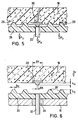
Die grundlegenden funktionalen Größen des Verbindungsprinzips sind in den FIG. 5 und 6 aufgezeigt:
- Durchmesser der gasdichten Kontaktstelle Ø K
Der Durchmesser Ø K muß so groß gewählt werden, daß beim ausgewählten metallischen Werkstoff die Stromtragfähigkeit gewährleistet ist. - Durchmesser des elastisch gelagerten Kontaktes Ø S
Der Durchmesser Ø S muß so groß gewählt werden, daß der elastische, elektrisch isolierende Werkstoff, der vorzugsweise aus Silikon besteht, nicht beschädigt wird bzw. beim Erzeugen der Rückstellkraft nicht über seine Elastizitätsgrenze hinaus beansprucht wird. - Verformungsweg s
Wenn das Anschlußstück an dem auf der Stirnseite des Gehäuses angeordneten Körper anliegt, werden die Dichtungsstege durch den Verschlußmechanismus um den Verformungsweg s in den Formkörper gedrückt. Die resultierende Rückstellkraft erzeugt die Dichtungskraft F D und die Kontaktkraft F K . Shorehärte X und Elastizitätsgrenze des elastischen Werkstoffes spielen hierbei eine Rolle. - Shorehärte X
Je höher die Shorehärte des elastischen Werkstoffes, desto höher ist die Rückstellkraft bei gegebenem Verformungsweg. - Überstehende Höhe des Kontaktes h K
Die mit dem Verschlußmechanismus erzeugte Kraft erzeugt sowohl den Druck auf den Dichtungsstegen als auch auf den Kontaktstellen. Werden die überstehende Höhe des Kontaktes h K und die Höhe der Dichtungsstege h D gleich gewählt, so verteilt sich der Druck proportional zu den jeweiligen Flächen, der durch die Federwirkung des elastischen Werkstoffes unter dem Verformungsweg s erzeugt wird. Wird die überstehende Höhe des Kontaktes h K anders als die Höhe der Dichtungsstege h D gewählt, so wird der volle Verformungsweg s nur bei einem der beiden Kontakte wirksam. Auf diese Weise kann der zu erzeugende Druck auf der Kontaktstelle und der zu erzeugende Druck auf den Dichtungsstegen unabhängig von deren Flächenverhältnissen eingestellt werden. - Höhe der Dichtungsstege h D
Es gilt der oben beschriebene Zusammenhang zur überstehenden Höhe des Kontaktes. Die erforderliche Höhe der Dichtungsstege hängt von der gesamten Geometrie der Dichtungsstege, des elastischen Werkstoffes und seiner Shorehärte ab. Wenn maximaler Druck auf den Dichtungsstegen herrschen soll, darf der elastische Werkstoff nicht an den Formkörper zwischen den Dichtungsstegen gepreßt werden. Die Höhe muß entsprechend gewählt werden und entspricht maximal dem Verformungsweg s . - Breite der Dichtungsstege b D
Je schmäler die Dichtungsstege gewählt werden, desto höher ist der Druck, jedoch darf der elastische Werkstoffnicht beschädigt werden.
- Diameter of the gastight contact point Ø K
The diameter Ø K must be chosen so large that the current carrying capacity is guaranteed for the selected metallic material. - Diameter of the elastically mounted contact Ø S
The diameter Ø S must be chosen so large that the elastic, electrically insulating material, which preferably consists of silicone, is not damaged or is not stressed beyond its elastic limit when the restoring force is generated. - Deformation path s
When the connector abuts the body arranged on the end face of the housing, the sealing webs are pressed into the molded body by the locking mechanism by the deformation path s . The resulting restoring force generates the sealing force F D and the contact force F K. Shore hardness X and elasticity limit of the elastic material play a role here. - Shore hardness X
The higher the Shore hardness of the elastic material, the higher the restoring force for a given deformation path. - Projecting height of the contact h K
The force generated by the locking mechanism creates both the pressure on the sealing webs and on the contact points. If the protruding height of the contact h K and the height of the sealing webs h D are chosen to be the same, the pressure is distributed proportionally to the respective surfaces which is generated by the spring action of the elastic material under the deformation path s . If the protruding height of the contact h K is chosen differently than the height of the sealing webs h D , the full deformation path s is only effective for one of the two contacts. In this way, the pressure to be generated on the contact point and the pressure to be generated on the sealing webs can be set independently of their surface conditions. - Height of the sealing webs h D
The relationship to the protruding amount of contact described above applies. The required height of the sealing webs depends on the overall geometry of the sealing webs, the elastic material and its Shore hardness. If maximum pressure is to be exerted on the sealing webs, the elastic material must not be pressed against the molded body between the sealing webs. The height must be chosen accordingly and corresponds at most to the deformation path s . - Width of the sealing webs b D
The narrower the sealing webs, the higher the pressure, but the elastic material must not be damaged.
Bei einer Stromtragfähigkeit im mA-Bereich kann der Raumbedarf der Kontaktanordnungen im Vergleich zu den oben aufgeführten normierten Herzschrittmachersteckverbindungen wesentlich minimiert werden.With a current carrying capacity in the mA range, the space requirement of the contact arrangements can be significantly minimized compared to the standardized pacemaker plug connections listed above.
Der Verschlußmechanismus muß die Anschlußstücke mit einer definierten Verschlußkraft gegen das Gehäuse drücken, so daß ein gasdichter Kontaktverschluß entsteht und die Dichtwirkung gewährleistet ist. Bevor die Kraft auf den elastischen Werkstoff einwirkt, der über den Verformungsweg s eine federartige Rückstellkraft erzeugt, müssen die Anschlußstücke in der exakt richtigen Position sein. Eine einfache Lösung stellt das Einlegen der Anschlußstücke in die Endkappe dar, die mit Hilfe einer Schraube mit definiertem Drehmoment an das Gehäuse gezogen wird. Dieser Prozeß ist jedoch nur bedingt möglich, wenn das Gehäuse bereits in einem Knochenbett verankert ist, weil der Verschluß von vorn erfolgt.The locking mechanism must press the connecting pieces against the housing with a defined locking force, so that a gas-tight contact lock is created and the sealing effect is guaranteed. Before the force acts on the elastic material, which produces a spring-like restoring force via the deformation path s , the connecting pieces must be in the exactly correct position. A simple solution is to insert the connectors into the end cap, which is pulled to the housing with a screw with a defined torque. However, this process is only possible to a limited extent if the housing is already anchored in a bone bed because the closure takes place from the front.
Um den Verschlußmechanismus von oben bedienen zu können, weist bei der in den FIG. 7 und 8 veranschaulichten abgewandelten Ausführungsform das perspektivisch gezeigte Gehäuse 40 an der Frontseite eine Art Wanne 42 auf, in welche Anschlußstücke 44 von oben eingebracht werden. Diese Anschlußstücke werden mit Hilfe einer im Bereich der Wanne 42 aufzusetzenden Abdeckung 46 in die exakte Position gebracht und dann über einen Keil 48 um einen definierten Verformungsweg gegen das Gehäuse 40 gedrückt. Die umlaufende Kontur der Anschlußstücke 44 und die entsprechende Aufnahme in der Wanne 42 können in der oben erwähnten Weise so gestaltet werden, daß kein Anschlußstück in die Aufnahme des anderen paßt. Ferner ist in FIG. 7 ein Anschlußstück 44 dargestellt, das für eine vierpolige Verbindung ausgelegt ist.In order to be able to operate the locking mechanism from above, the device shown in FIGS. 7 and 8 illustrate a modified embodiment of the
Entsprechend FIG. 8 wird nach dem Einsetzen der Anschlußstücke 44 in die Wanne 42 die Abdeckung 46 aufgesetzt. Durch eine in der Abdeckung vorgesehene Ausnehmung 50 wird ein Keil 48 zwischen die Anschlußstücke 44 und die dem Gehäuse 40 entfernt liegende Wandseite 51 der Wanne 42 eingebracht, so daß die Anschlußstücke 44 um den definierten Verformungsweg in Richtung auf die die Kontakte aufweisende Wandfläche 54 des Gehäuses 40 geschoben und gegen diese angepreßt werden. Dabei kann der Keil 48 mit Hilfe einer Schraube 52 eingebracht und fixiert werden, oder es kann ein (nicht gezeigter) Rastmechanismus vorgesehen sein, mittels dessen der manuell eingebrachte Keil 48 in der Einbaulage fixiert wird.According to FIG. 8, the
Das vorstehend beschriebene Verbindungsprinzip zwischen einer zu implantierenden Vorrichtung und aktorischen und/oder sensorischen Komponenten erlaubt eine Isolationsimpedanz zwischen den einzelnen Kontakten von mehr als 50 MΩ, wobei dieser Wert die von der oben erwähnten DIN-Norm für Herzschrittmacher geforderte Isolationsimpedanz von 50 kΩ um ein Vielfaches übersteigt. Zum Beispiel sind bei einem implantierbaren Hörgerät Verstärkungen von > 80 dB zwischen Sensor und Aktor erforderlich, ohne daß eine Rückkopplung zwischen den Sensorsignalen und den Aktorsignalen auftritt, und es sollten über die Kontaktanordnung analoge Signale im µV-Bereich verzerrungsfrei übertragen werden können. Die vorgeschlagene implantierbare Einheit erlaubt es somit, die für implantierbare Hörgeräte geltenden hohen Ansprüche an die Art der Kontaktgebung zu befriedigen, die den Anforderungen der Signalübertragung im Audio- und HiFi-Bereich entsprechen.The connection principle described above between a device to be implanted and actuator and / or sensory components allows an insulation impedance between the individual contacts of more than 50 MΩ, this value multiplying the insulation impedance of 50 kΩ required by the aforementioned DIN standard for pacemakers by a multiple exceeds. For example, an implantable hearing aid requires gains of> 80 dB between the sensor and the actuator without feedback between the sensor signals and the actuator signals, and analog signals in the µV range should be able to be transmitted without distortion via the contact arrangement. The proposed implantable unit thus makes it possible to satisfy the high demands on the type of contact which apply to implantable hearing aids and which correspond to the requirements of signal transmission in the audio and hi-fi field.
Trotz eines hohen möglichen Miniaturisierungsgrades erfolgt das Schließen der Kontaktanordnungen einfach, sicher und zuverlässig. Ohne die Verwendung der typischen männlichen und weiblichen Ausbildung der Kontakte in Form eines Stiftes und einer zugehörigen Buchse besteht bei den vorgeschlagenen Systemen keine Gefahr, daß die Kontakte abgebrochen, verbogen oder sonstwie beschädigt werden können.Despite a high degree of miniaturization, the contact arrangements can be closed easily, safely and reliably. Without the use of the typical male and female design of the contacts in the form of a pin and an associated socket, there is no risk in the proposed systems that the contacts can be broken, bent or otherwise damaged.
Claims (16)
Applications Claiming Priority (2)
| Application Number | Priority Date | Filing Date | Title |
|---|---|---|---|
| DE19622669A DE19622669A1 (en) | 1996-06-05 | 1996-06-05 | Implantable unit |
| DE19622669 | 1996-06-05 |
Publications (3)
| Publication Number | Publication Date |
|---|---|
| EP0811397A2 true EP0811397A2 (en) | 1997-12-10 |
| EP0811397A3 EP0811397A3 (en) | 1999-05-19 |
| EP0811397B1 EP0811397B1 (en) | 2005-03-23 |
Family
ID=7796276
Family Applications (1)
| Application Number | Title | Priority Date | Filing Date |
|---|---|---|---|
| EP97109044A Expired - Lifetime EP0811397B1 (en) | 1996-06-05 | 1997-06-04 | Implantable unit |
Country Status (4)
| Country | Link |
|---|---|
| US (1) | US5755743A (en) |
| EP (1) | EP0811397B1 (en) |
| AT (1) | ATE291464T1 (en) |
| DE (2) | DE19622669A1 (en) |
Cited By (3)
| Publication number | Priority date | Publication date | Assignee | Title |
|---|---|---|---|---|
| WO2018175321A1 (en) * | 2017-03-23 | 2018-09-27 | Verily Life Sciences Llc | Implantable connector |
| JP2019522521A (en) * | 2016-07-06 | 2019-08-15 | ニューロループ ゲーエムベーハー | Implantable electromechanical plug connector |
| WO2019219437A1 (en) | 2018-05-17 | 2019-11-21 | Neuroloop GmbH | Implantable electromechanical plug connector |
Families Citing this family (105)
| Publication number | Priority date | Publication date | Assignee | Title |
|---|---|---|---|---|
| US5871514A (en) * | 1997-08-01 | 1999-02-16 | Medtronic, Inc. | Attachment apparatus for an implantable medical device employing ultrasonic energy |
| US6088608A (en) | 1997-10-20 | 2000-07-11 | Alfred E. Mann Foundation | Electrochemical sensor and integrity tests therefor |
| US6198969B1 (en) * | 1998-02-12 | 2001-03-06 | Advanced Bionics Corporation | Implantable connector for multi-output neurostimulators |
| DE19837913C2 (en) * | 1998-08-20 | 2000-09-28 | Implex Hear Tech Ag | Implantable device with a charging current feed arrangement having a receiving coil |
| DE19837912C1 (en) | 1998-08-20 | 1999-10-28 | Implex Hear Tech Ag | Energy supply module for implanted device e.g. hearing aid or tinnitus masking device, heart pacemaker or drug dispenser |
| SE9803692D0 (en) * | 1998-10-27 | 1998-10-27 | Pacesetter Ab | A connector for a heart stimulator |
| DE19858399C2 (en) | 1998-12-17 | 2003-02-20 | Phonak Ag Staefa | Electroacoustic transducer for hearing aids for airborne sound radiation in the external auditory canal |
| DE19858398C1 (en) | 1998-12-17 | 2000-03-02 | Implex Hear Tech Ag | Tinnitus treatment implant comprises a gas-tight biocompatible electroacoustic transducer for implantation in a mastoid cavity |
| DE19859171C2 (en) * | 1998-12-21 | 2000-11-09 | Implex Hear Tech Ag | Implantable hearing aid with tinnitus masker or noiser |
| DE19914992A1 (en) | 1999-04-01 | 2000-12-07 | Implex Hear Tech Ag | Implantable hearing system with audiometer |
| DE19914993C1 (en) | 1999-04-01 | 2000-07-20 | Implex Hear Tech Ag | Fully implantable hearing system with telemetric sensor testing has measurement and wireless telemetry units on implant side for transmitting processed signal to external display/evaluation unit |
| FR2811578B1 (en) * | 2000-07-11 | 2003-01-31 | Ela Medical Sa | CONNECTOR HEAD OF AN IMPLANTABLE ACTIVE MEDICAL DEVICE SUCH AS A CARDIAC STIMULATOR, DEFIBRILLATOR, CARDIOVERTER AND / OR MULTI-SITE DEVICE, AND METHOD FOR BONDING THIS HEAD TO THE CASE |
| FR2812204B1 (en) * | 2000-07-31 | 2003-02-07 | Ela Medical Sa | ACTIVE IMPLANTABLE MEDICAL DEVICE SUCH AS A CARDIAC STIMULATOR, DEFIBRILLATOR AND / OR CARDIOVERTER COMPRISING A REMOVABLE CONNECTOR HEAD |
| US7146212B2 (en) | 2000-09-18 | 2006-12-05 | Cameron Health, Inc. | Anti-bradycardia pacing for a subcutaneous implantable cardioverter-defibrillator |
| US6721597B1 (en) | 2000-09-18 | 2004-04-13 | Cameron Health, Inc. | Subcutaneous only implantable cardioverter defibrillator and optional pacer |
| US7039465B2 (en) * | 2000-09-18 | 2006-05-02 | Cameron Health, Inc. | Ceramics and/or other material insulated shell for active and non-active S-ICD can |
| US7069080B2 (en) | 2000-09-18 | 2006-06-27 | Cameron Health, Inc. | Active housing and subcutaneous electrode cardioversion/defibrillating system |
| US6754528B2 (en) | 2001-11-21 | 2004-06-22 | Cameraon Health, Inc. | Apparatus and method of arrhythmia detection in a subcutaneous implantable cardioverter/defibrillator |
| US6975906B2 (en) * | 2001-02-08 | 2005-12-13 | Wilson Greatbatch Ltd. | One piece header assembly over molded to an implantable medical device |
| US8123814B2 (en) | 2001-02-23 | 2012-02-28 | Biomet Manufacturing Corp. | Method and appartus for acetabular reconstruction |
| US7597715B2 (en) | 2005-04-21 | 2009-10-06 | Biomet Manufacturing Corp. | Method and apparatus for use of porous implants |
| US6738672B2 (en) * | 2001-06-18 | 2004-05-18 | The Alfred E. Mann Foundation For Scientific Research | Miniature implantable connectors |
| US8364278B2 (en) * | 2002-01-29 | 2013-01-29 | Boston Scientific Neuromodulation Corporation | Lead assembly for implantable microstimulator |
| US20030199948A1 (en) * | 2002-04-19 | 2003-10-23 | Kokones Scott B. | Multiport neurological screening cable |
| EP1417986A1 (en) * | 2002-11-05 | 2004-05-12 | Wilson Greatbatch Technologies, Inc. | One piece header assembly for an implantable medical device |
| US7596408B2 (en) * | 2002-12-09 | 2009-09-29 | Medtronic, Inc. | Implantable medical device with anti-infection agent |
| AU2003297725A1 (en) * | 2002-12-09 | 2004-06-30 | Medtronic, Inc. | Overmold for a modular implantable medical device |
| US7539542B1 (en) | 2003-01-09 | 2009-05-26 | Boston Scientific Neuromodulation Corporation | Lead connector, lead adapter, and lead insertion apparatus |
| US7263401B2 (en) * | 2003-05-16 | 2007-08-28 | Medtronic, Inc. | Implantable medical device with a nonhermetic battery |
| US20050003268A1 (en) * | 2003-05-16 | 2005-01-06 | Scott Erik R. | Battery housing configuration |
| US7317947B2 (en) * | 2003-05-16 | 2008-01-08 | Medtronic, Inc. | Headset recharger for cranially implantable medical devices |
| US20050004637A1 (en) * | 2003-05-16 | 2005-01-06 | Ruchika Singhal | Explantation of implantable medical device |
| US7303422B2 (en) * | 2003-06-04 | 2007-12-04 | Neurostream Technologies | Implantable modular, multi-channel connector system for nerve signal sensing and electrical stimulation applications |
| US7596399B2 (en) * | 2004-04-29 | 2009-09-29 | Medtronic, Inc | Implantation of implantable medical device |
| US20050245984A1 (en) * | 2004-04-30 | 2005-11-03 | Medtronic, Inc. | Implantable medical device with lubricious material |
| DE102005007291B4 (en) * | 2005-02-17 | 2009-06-25 | INTER CONTROL Hermann Köhler Elektrik GmbH & Co KG | Sensor carrier unit with permanently elastic adapter |
| US7756579B2 (en) * | 2005-02-22 | 2010-07-13 | Depuy International Ltd. | Implantable sensor |
| US8021432B2 (en) | 2005-12-05 | 2011-09-20 | Biomet Manufacturing Corp. | Apparatus for use of porous implants |
| US8266780B2 (en) | 2005-04-21 | 2012-09-18 | Biomet Manufacturing Corp. | Method and apparatus for use of porous implants |
| US8292967B2 (en) | 2005-04-21 | 2012-10-23 | Biomet Manufacturing Corp. | Method and apparatus for use of porous implants |
| US8066778B2 (en) | 2005-04-21 | 2011-11-29 | Biomet Manufacturing Corp. | Porous metal cup with cobalt bearing surface |
| US7957805B2 (en) * | 2005-06-01 | 2011-06-07 | Boston Scientific Neuromodulation Corporation | Implantable microstimulator with external electrodes disposed on a film substrate and methods of manufacture and use |
| US8326425B2 (en) * | 2006-03-30 | 2012-12-04 | Cardiac Pacemakers, Inc. | Feedthrough connector for implantable device |
| US7803014B2 (en) * | 2006-03-30 | 2010-09-28 | Cardiac Pacemakers, Inc. | Implantable medical device assembly and manufacturing method |
| US9084901B2 (en) * | 2006-04-28 | 2015-07-21 | Medtronic, Inc. | Cranial implant |
| EP2522392A3 (en) * | 2006-08-28 | 2013-01-23 | Neurostream Technologies General Partnership | High density implantable connector |
| JP4379467B2 (en) * | 2006-12-11 | 2009-12-09 | 日産自動車株式会社 | Battery module |
| DE102007006088A1 (en) * | 2007-02-07 | 2008-08-14 | Biotronik Crm Patent Ag | Contact module for a medical implant |
| US8494195B2 (en) * | 2007-02-07 | 2013-07-23 | Starkey Laboratories, Inc. | Electrical contacts using conductive silicone in hearing assistance devices |
| US7942686B2 (en) * | 2007-05-03 | 2011-05-17 | Deringer-Ney, Inc. | Electrical barrier and moisture seal for an implanted medical device |
| US8206175B2 (en) | 2007-05-03 | 2012-06-26 | Deringer-Ney, Inc. | Visual indicator of proper interconnection for an implanted medical device |
| US8385573B2 (en) * | 2007-09-19 | 2013-02-26 | Starkey Laboratories, Inc. | System for hearing assistance device including receiver in the canal |
| WO2009045772A1 (en) * | 2007-10-03 | 2009-04-09 | Medtronic, Inc. | Connector assemblies for implantable medical electrical systems |
| US8108045B2 (en) * | 2007-10-29 | 2012-01-31 | Cretex Orthopaedics, Inc. | Set screw-less pacemaker header with lead lock system |
| US8065009B2 (en) * | 2008-01-25 | 2011-11-22 | Greatbatch Ltd. | Header over-molded on a feedthrough assembly for an implantable device |
| US8867765B2 (en) | 2008-02-06 | 2014-10-21 | Starkey Laboratories, Inc. | Antenna used in conjunction with the conductors for an audio transducer |
| US8116495B2 (en) * | 2008-03-31 | 2012-02-14 | Starkey Laboratories, Inc. | Reinforced earbud device, system and method |
| US20090281623A1 (en) * | 2008-05-12 | 2009-11-12 | Medtronic, Inc. | Customization of implantable medical devices |
| US20090287277A1 (en) * | 2008-05-19 | 2009-11-19 | Otologics, Llc | Implantable neurostimulation electrode interface |
| CA2639555A1 (en) | 2008-08-11 | 2008-12-15 | Hyman Ngo | High definition litho applique and emblems |
| US8781141B2 (en) | 2008-08-27 | 2014-07-15 | Starkey Laboratories, Inc. | Modular connection assembly for a hearing assistance device |
| US20100069997A1 (en) * | 2008-09-16 | 2010-03-18 | Otologics, Llc | Neurostimulation apparatus |
| US9393432B2 (en) | 2008-10-31 | 2016-07-19 | Medtronic, Inc. | Non-hermetic direct current interconnect |
| US8798299B1 (en) | 2008-12-31 | 2014-08-05 | Starkey Laboratories, Inc. | Magnetic shielding for communication device applications |
| US9044588B2 (en) * | 2009-04-16 | 2015-06-02 | Cochlear Limited | Reference electrode apparatus and method for neurostimulation implants |
| WO2010121240A2 (en) * | 2009-04-17 | 2010-10-21 | Otologics, Llc | Neurostimulation electrode array and method of manufacture |
| US8771166B2 (en) | 2009-05-29 | 2014-07-08 | Cochlear Limited | Implantable auditory stimulation system and method with offset implanted microphones |
| US9002047B2 (en) * | 2009-07-23 | 2015-04-07 | Starkey Laboratories, Inc. | Method and apparatus for an insulated electromagnetic shield for use in hearing assistance devices |
| WO2011034894A1 (en) * | 2009-09-15 | 2011-03-24 | Deringer-Ney, Inc. | Electrical connection system and method for implantable medical devices |
| US8638965B2 (en) | 2010-07-14 | 2014-01-28 | Starkey Laboratories, Inc. | Receiver-in-canal hearing device cable connections |
| AU2011349264B2 (en) * | 2010-12-21 | 2016-07-14 | Stryker Corporation | Powered surgical tool with a control module and a sealed unit for protecting a circuit board of the control module from the effects of sterilization |
| US9049526B2 (en) | 2011-03-19 | 2015-06-02 | Starkey Laboratories, Inc. | Compact programming block connector for hearing assistance devices |
| US9511216B2 (en) | 2011-09-28 | 2016-12-06 | Advanced Bionics Ag | Modular biomedical implants |
| US8929986B2 (en) | 2011-11-04 | 2015-01-06 | Nevro Corporation | Medical device communication and charging assemblies for use with implantable signal generators, and associated systems and methods |
| US20130200055A1 (en) * | 2012-02-02 | 2013-08-08 | Lincoln Global, Inc. | Power source and wire feeder matching |
| EP2991723A4 (en) * | 2013-05-03 | 2017-02-01 | Nevro Corporation | Molded headers for implantable signal generators, and associated systems and methods |
| US9884197B2 (en) * | 2013-07-01 | 2018-02-06 | Newsouth Innovations Pty Ltd | Encapsulated electronic circuit |
| US9906879B2 (en) | 2013-11-27 | 2018-02-27 | Starkey Laboratories, Inc. | Solderless module connector for a hearing assistance device assembly |
| US9913052B2 (en) | 2013-11-27 | 2018-03-06 | Starkey Laboratories, Inc. | Solderless hearing assistance device assembly and method |
| AU2015264561B2 (en) | 2014-05-20 | 2020-02-20 | Nevro Corporation | Implanted pulse generators with reduced power consumption via signal strength/duration characteristics, and associated systems and methods |
| EP3191176B1 (en) | 2014-10-22 | 2024-04-10 | Nevro Corp. | Systems and methods for extending the life of an implanted pulse generator battery |
| DE102014115859A1 (en) * | 2014-10-30 | 2016-05-04 | Albert-Ludwigs-Universität Freiburg | Implantable connector |
| US9517344B1 (en) | 2015-03-13 | 2016-12-13 | Nevro Corporation | Systems and methods for selecting low-power, effective signal delivery parameters for an implanted pulse generator |
| US9956394B2 (en) | 2015-09-10 | 2018-05-01 | Boston Scientific Neuromodulation Corporation | Connectors for electrical stimulation systems and methods of making and using |
| US10342983B2 (en) | 2016-01-14 | 2019-07-09 | Boston Scientific Neuromodulation Corporation | Systems and methods for making and using connector contact arrays for electrical stimulation systems |
| US11071869B2 (en) | 2016-02-24 | 2021-07-27 | Cochlear Limited | Implantable device having removable portion |
| DE102016107414A1 (en) * | 2016-04-21 | 2017-10-26 | Biotronik Se & Co. Kg | Implementation of an implantable medical electronic device and implantable medical electronic device |
| US10201713B2 (en) | 2016-06-20 | 2019-02-12 | Boston Scientific Neuromodulation Corporation | Threaded connector assembly and methods of making and using the same |
| US10307602B2 (en) | 2016-07-08 | 2019-06-04 | Boston Scientific Neuromodulation Corporation | Threaded connector assembly and methods of making and using the same |
| US10543374B2 (en) | 2016-09-30 | 2020-01-28 | Boston Scientific Neuromodulation Corporation | Connector assemblies with bending limiters for electrical stimulation systems and methods of making and using same |
| DE102016222710A1 (en) | 2016-11-18 | 2018-05-24 | Neuroloop GmbH | Implantable electrical contact arrangement |
| US10905871B2 (en) | 2017-01-27 | 2021-02-02 | Boston Scientific Neuromodulation Corporation | Lead assemblies with arrangements to confirm alignment between terminals and contacts |
| WO2018160495A1 (en) | 2017-02-28 | 2018-09-07 | Boston Scientific Neuromodulation Corporation | Toolless connector for latching stimulation leads and methods of making and using |
| US10603499B2 (en) | 2017-04-07 | 2020-03-31 | Boston Scientific Neuromodulation Corporation | Tapered implantable lead and connector interface and methods of making and using |
| US10918873B2 (en) | 2017-07-25 | 2021-02-16 | Boston Scientific Neuromodulation Corporation | Systems and methods for making and using an enhanced connector of an electrical stimulation system |
| US11045656B2 (en) | 2017-09-15 | 2021-06-29 | Boston Scientific Neuromodulation Corporation | Biased lead connector for operating room cable assembly and methods of making and using |
| AU2018331512B2 (en) | 2017-09-15 | 2021-06-24 | Boston Scientific Neuromodulation Corporation | Actuatable lead connector for an operating room cable assembly and methods of making and using |
| US11139603B2 (en) | 2017-10-03 | 2021-10-05 | Boston Scientific Neuromodulation Corporation | Connectors with spring contacts for electrical stimulation systems and methods of making and using same |
| US11103712B2 (en) | 2018-01-16 | 2021-08-31 | Boston Scientific Neuromodulation Corporation | Connector assemblies with novel spacers for electrical stimulation systems and methods of making and using same |
| JP6835028B2 (en) * | 2018-03-30 | 2021-02-24 | 横河電機株式会社 | Airtight terminal and sensor unit |
| EP3790623B1 (en) | 2018-05-11 | 2023-07-05 | Boston Scientific Neuromodulation Corporation | Connector assembly for an electrical stimulation system |
| US10933238B2 (en) | 2019-01-31 | 2021-03-02 | Nevro Corp. | Power control circuit for sterilized devices, and associated systems and methods |
| US11357992B2 (en) | 2019-05-03 | 2022-06-14 | Boston Scientific Neuromodulation Corporation | Connector assembly for an electrical stimulation system and methods of making and using |
| US20210244953A1 (en) * | 2020-02-10 | 2021-08-12 | Wisconsin Alumni Research Foundation | Electrical Connector and Cover for Simultaneously Connecting Wires, Bedside Monitor, and Temporary Pacemaker |
| US11621515B2 (en) * | 2021-03-25 | 2023-04-04 | Neuropace, Inc. | Connector assembly for active implantable medical device |
Citations (4)
| Publication number | Priority date | Publication date | Assignee | Title |
|---|---|---|---|---|
| GB2134335A (en) * | 1983-01-27 | 1984-08-08 | Commw Of Australia | Sealed electrical connector for cochlear prosthetic package |
| US4495917A (en) * | 1982-03-26 | 1985-01-29 | The Regents Of The University Of California | Surgically implantable disconnect device |
| US5046242A (en) * | 1982-07-27 | 1991-09-10 | Commonwealth Of Australia | Method of making feedthrough assemblies having hermetic seals between electrical feedthrough elements and ceramic carriers therefor |
| US5336246A (en) * | 1993-06-23 | 1994-08-09 | Telectronics Pacing Systems, Inc. | Lead connector assembly for medical device and method of assembly |
Family Cites Families (18)
| Publication number | Priority date | Publication date | Assignee | Title |
|---|---|---|---|---|
| JPS54158691A (en) * | 1977-10-21 | 1979-12-14 | Univ Melbourne | Electrical connector |
| ES479225A1 (en) * | 1978-04-07 | 1979-12-01 | Medtronic Inc | Body implantable stimulator and connector therefor. |
| US4262673A (en) * | 1979-10-11 | 1981-04-21 | Mieczyslaw Mirowski | Fluid tight coupling for electrode lead |
| US4605007A (en) * | 1980-06-02 | 1986-08-12 | Medtronic, Inc. | Temporary package for an electrical component |
| EP0052690A1 (en) * | 1980-11-21 | 1982-06-02 | Precimed S.A. | Arrangement for the connection of the probe electrode to the output terminal of a cardiac pacemaker |
| JPS5793343U (en) * | 1980-11-26 | 1982-06-08 | ||
| DE3331620A1 (en) * | 1982-09-03 | 1984-03-15 | Mirowski, Mieczyslaw, Owings Mills, Md. | HERMETICALLY SEALED CONNECTION WITH PLUG PART AND PLUG RECEIVER FOR AN IMPLANTABLE MEDICAL DEVICE |
| DE8712042U1 (en) * | 1987-09-03 | 1988-10-20 | Biotronik Mess- Und Therapiegeraete Gmbh & Co Ingenieurbuero Berlin, 1000 Berlin, De | |
| US4848346A (en) * | 1987-12-02 | 1989-07-18 | Siemens-Pacesetter, Inc. | Pacemaker connector system |
| US4934367A (en) * | 1988-04-22 | 1990-06-19 | Medtronic, Inc. | In-line pacemaker connector system |
| US4934366A (en) * | 1988-09-01 | 1990-06-19 | Siemens-Pacesetter, Inc. | Feedthrough connector for implantable medical device |
| JPH03502656A (en) * | 1988-09-01 | 1991-06-20 | ペースセッター アクチボラゲット | Feed-through connectors for implantable medical devices |
| US4966564A (en) * | 1988-09-09 | 1990-10-30 | Telectronics, N.V. | Electrical connector between electrode leads and pacemaker terminal |
| FR2658083B1 (en) * | 1990-02-14 | 1992-05-07 | Ela Medical Sa | UNIVERSAL MALE CONNECTOR FOR SINGLE POLE HEART STIMULATION PROBE AND MOUNTING METHOD THEREOF. |
| US5076270A (en) * | 1990-05-03 | 1991-12-31 | Siemens-Pacesetter, Inc. | Apparatus and method for making electrical connections in an implantable pacemaker |
| US5176136A (en) * | 1991-08-07 | 1993-01-05 | Vitatron Medical, B.V. | Pacemaker with improved connector block |
| US5257622A (en) * | 1991-09-19 | 1993-11-02 | Medtronic, Inc. | Locking connector for implantable device |
| US5324311A (en) * | 1992-09-04 | 1994-06-28 | Siemens Pacesetter, Inc. | Coaxial bipolar connector assembly for implantable medical device |
-
1996
- 1996-06-05 DE DE19622669A patent/DE19622669A1/en not_active Ceased
- 1996-10-16 US US08/733,140 patent/US5755743A/en not_active Expired - Lifetime
-
1997
- 1997-06-04 DE DE59712238T patent/DE59712238D1/en not_active Expired - Fee Related
- 1997-06-04 AT AT97109044T patent/ATE291464T1/en not_active IP Right Cessation
- 1997-06-04 EP EP97109044A patent/EP0811397B1/en not_active Expired - Lifetime
Patent Citations (4)
| Publication number | Priority date | Publication date | Assignee | Title |
|---|---|---|---|---|
| US4495917A (en) * | 1982-03-26 | 1985-01-29 | The Regents Of The University Of California | Surgically implantable disconnect device |
| US5046242A (en) * | 1982-07-27 | 1991-09-10 | Commonwealth Of Australia | Method of making feedthrough assemblies having hermetic seals between electrical feedthrough elements and ceramic carriers therefor |
| GB2134335A (en) * | 1983-01-27 | 1984-08-08 | Commw Of Australia | Sealed electrical connector for cochlear prosthetic package |
| US5336246A (en) * | 1993-06-23 | 1994-08-09 | Telectronics Pacing Systems, Inc. | Lead connector assembly for medical device and method of assembly |
Cited By (5)
| Publication number | Priority date | Publication date | Assignee | Title |
|---|---|---|---|---|
| JP2019522521A (en) * | 2016-07-06 | 2019-08-15 | ニューロループ ゲーエムベーハー | Implantable electromechanical plug connector |
| WO2018175321A1 (en) * | 2017-03-23 | 2018-09-27 | Verily Life Sciences Llc | Implantable connector |
| US10608354B2 (en) | 2017-03-23 | 2020-03-31 | Verily Life Sciences Llc | Implantable connector with two electrical components |
| US11450977B2 (en) | 2017-03-23 | 2022-09-20 | Verily Life Sciences Llc | Implantable connector including at least one electrical component |
| WO2019219437A1 (en) | 2018-05-17 | 2019-11-21 | Neuroloop GmbH | Implantable electromechanical plug connector |
Also Published As
| Publication number | Publication date |
|---|---|
| DE19622669A1 (en) | 1997-12-11 |
| US5755743A (en) | 1998-05-26 |
| ATE291464T1 (en) | 2005-04-15 |
| EP0811397A3 (en) | 1999-05-19 |
| DE59712238D1 (en) | 2005-04-28 |
| EP0811397B1 (en) | 2005-03-23 |
Similar Documents
| Publication | Publication Date | Title |
|---|---|---|
| EP0811397B1 (en) | Implantable unit | |
| DE19837913C2 (en) | Implantable device with a charging current feed arrangement having a receiving coil | |
| DE602004009585T2 (en) | Connecting pieces for connecting a line to an implantable medical device | |
| EP0263244B1 (en) | Apparatus for the electronic testing of printed circuits with contact points in an extremely fine raster (1/20th to 1/10th inch) | |
| EP0982784B1 (en) | Battery pack for an implantable medical device | |
| DE3830134C2 (en) | One-piece electrical socket and housing assembly equipped with it | |
| DE60104241T2 (en) | Active implantable medical device, in particular pacemaker, defibrillator, and / or cardioverter, with a detachable connection head | |
| DE4116520A1 (en) | IMPLANTABLE CONDUCTIVE CONNECTOR | |
| WO1992012878A1 (en) | Electrohydraulic pressure regulator | |
| DE4427642A1 (en) | Electrical connector | |
| WO2019201390A1 (en) | Shielded plug connector module for a modular industrial plug connector | |
| WO2019015717A1 (en) | Plasma treatment device | |
| EP0694997A2 (en) | Connection device for the electric connection of contact elements | |
| EP0757409B1 (en) | Electrical connector | |
| DE19944909A1 (en) | Electrical connection unit for electrically driven system, esp. positional measurement system, has first and second electrical contacts connected together in pairs | |
| DE202007018766U1 (en) | Contact module for a medical implant | |
| EP2885841B1 (en) | Contact-making device | |
| DE19535979B4 (en) | Plug housing with a base and a locking part and use of the plug housing | |
| DE3538193C2 (en) | ||
| EP0163053B1 (en) | Voltage surge arrester | |
| EP0603652A1 (en) | Plug connector, especially of SUB-D-type | |
| EP0659098B1 (en) | Implant for electrostimulation of tissues | |
| EP3884546B1 (en) | Implantable electrical connecting device | |
| DE69725341T2 (en) | CONTACT ELEMENTS OF A MULTIPOLE CONNECTOR ON AN ELECTRODE CABLE FOR AN IMPLANTABLE MEDICAL DEVICE | |
| DE3231690A1 (en) | Electrical connecting terminal for printed-circuit boards |
Legal Events
| Date | Code | Title | Description |
|---|---|---|---|
| PUAI | Public reference made under article 153(3) epc to a published international application that has entered the european phase |
Free format text: ORIGINAL CODE: 0009012 |
|
| AK | Designated contracting states |
Kind code of ref document: A2 Designated state(s): AT BE CH DE DK ES FR GB IT LI NL SE |
|
| PUAL | Search report despatched |
Free format text: ORIGINAL CODE: 0009013 |
|
| AK | Designated contracting states |
Kind code of ref document: A3 Designated state(s): AT BE CH DE DK ES FI FR GB GR IE IT LI LU MC NL PT SE |
|
| 17P | Request for examination filed |
Effective date: 19990528 |
|
| AKX | Designation fees paid |
Free format text: AT BE CH DE DK ES FR GB IT LI NL SE |
|
| RAP1 | Party data changed (applicant data changed or rights of an application transferred) |
Owner name: IMPLEX AKTIENGESELLSCHAFT HEARING TECHNOLOGY |
|
| RAP1 | Party data changed (applicant data changed or rights of an application transferred) |
Owner name: COCHLEAR LIMITED |
|
| 17Q | First examination report despatched |
Effective date: 20040102 |
|
| GRAP | Despatch of communication of intention to grant a patent |
Free format text: ORIGINAL CODE: EPIDOSNIGR1 |
|
| GRAS | Grant fee paid |
Free format text: ORIGINAL CODE: EPIDOSNIGR3 |
|
| GRAA | (expected) grant |
Free format text: ORIGINAL CODE: 0009210 |
|
| AK | Designated contracting states |
Kind code of ref document: B1 Designated state(s): AT BE CH DE DK ES FR GB IT LI NL SE |
|
| PG25 | Lapsed in a contracting state [announced via postgrant information from national office to epo] |
Ref country code: NL Free format text: LAPSE BECAUSE OF FAILURE TO SUBMIT A TRANSLATION OF THE DESCRIPTION OR TO PAY THE FEE WITHIN THE PRESCRIBED TIME-LIMIT Effective date: 20050323 Ref country code: IT Free format text: LAPSE BECAUSE OF FAILURE TO SUBMIT A TRANSLATION OF THE DESCRIPTION OR TO PAY THE FEE WITHIN THE PRE;WARNING: LAPSES OF ITALIAN PATENTS WITH EFFECTIVE DATE BEFORE 2007 MAY HAVE OCCURRED AT ANY TIME BEFORE 2007. THE CORRECT EFFECTIVE DATE MAY BE DIFFERENT FROM THE ONE RECORDED.SCRIBED TIME-LIMIT Effective date: 20050323 Ref country code: GB Free format text: LAPSE BECAUSE OF FAILURE TO SUBMIT A TRANSLATION OF THE DESCRIPTION OR TO PAY THE FEE WITHIN THE PRESCRIBED TIME-LIMIT Effective date: 20050323 |
|
| REG | Reference to a national code |
Ref country code: GB Ref legal event code: FG4D Free format text: NOT ENGLISH |
|
| REG | Reference to a national code |
Ref country code: CH Ref legal event code: EP |
|
| REF | Corresponds to: |
Ref document number: 59712238 Country of ref document: DE Date of ref document: 20050428 Kind code of ref document: P |
|
| PG25 | Lapsed in a contracting state [announced via postgrant information from national office to epo] |
Ref country code: DK Free format text: LAPSE BECAUSE OF FAILURE TO SUBMIT A TRANSLATION OF THE DESCRIPTION OR TO PAY THE FEE WITHIN THE PRESCRIBED TIME-LIMIT Effective date: 20050623 |
|
| PG25 | Lapsed in a contracting state [announced via postgrant information from national office to epo] |
Ref country code: LI Free format text: LAPSE BECAUSE OF NON-PAYMENT OF DUE FEES Effective date: 20050630 Ref country code: CH Free format text: LAPSE BECAUSE OF NON-PAYMENT OF DUE FEES Effective date: 20050630 Ref country code: BE Free format text: LAPSE BECAUSE OF NON-PAYMENT OF DUE FEES Effective date: 20050630 |
|
| PG25 | Lapsed in a contracting state [announced via postgrant information from national office to epo] |
Ref country code: ES Free format text: LAPSE BECAUSE OF FAILURE TO SUBMIT A TRANSLATION OF THE DESCRIPTION OR TO PAY THE FEE WITHIN THE PRESCRIBED TIME-LIMIT Effective date: 20050704 |
|
| NLV1 | Nl: lapsed or annulled due to failure to fulfill the requirements of art. 29p and 29m of the patents act | ||
| GBV | Gb: ep patent (uk) treated as always having been void in accordance with gb section 77(7)/1977 [no translation filed] |
Effective date: 20050323 |
|
| PG25 | Lapsed in a contracting state [announced via postgrant information from national office to epo] |
Ref country code: DE Free format text: LAPSE BECAUSE OF NON-PAYMENT OF DUE FEES Effective date: 20060103 |
|
| PLBE | No opposition filed within time limit |
Free format text: ORIGINAL CODE: 0009261 |
|
| STAA | Information on the status of an ep patent application or granted ep patent |
Free format text: STATUS: NO OPPOSITION FILED WITHIN TIME LIMIT |
|
| REG | Reference to a national code |
Ref country code: CH Ref legal event code: PL |
|
| 26N | No opposition filed |
Effective date: 20051227 |
|
| EN | Fr: translation not filed | ||
| BERE | Be: lapsed |
Owner name: COCHLEAR LTD Effective date: 20050630 |
|
| PG25 | Lapsed in a contracting state [announced via postgrant information from national office to epo] |
Ref country code: SE Free format text: LAPSE BECAUSE OF FAILURE TO SUBMIT A TRANSLATION OF THE DESCRIPTION OR TO PAY THE FEE WITHIN THE PRESCRIBED TIME-LIMIT Effective date: 20050623 |
|
| PGFP | Annual fee paid to national office [announced via postgrant information from national office to epo] |
Ref country code: AT Payment date: 20080602 Year of fee payment: 12 |
|
| PG25 | Lapsed in a contracting state [announced via postgrant information from national office to epo] |
Ref country code: FR Free format text: LAPSE BECAUSE OF NON-PAYMENT OF DUE FEES Effective date: 20050630 |
|
| PG25 | Lapsed in a contracting state [announced via postgrant information from national office to epo] |
Ref country code: FR Free format text: LAPSE BECAUSE OF NON-PAYMENT OF DUE FEES Effective date: 20050323 |
|
| PG25 | Lapsed in a contracting state [announced via postgrant information from national office to epo] |
Ref country code: AT Free format text: LAPSE BECAUSE OF NON-PAYMENT OF DUE FEES Effective date: 20090604 |