EP0811528A2 - Control installation - Google Patents
Control installation Download PDFInfo
- Publication number
- EP0811528A2 EP0811528A2 EP97103507A EP97103507A EP0811528A2 EP 0811528 A2 EP0811528 A2 EP 0811528A2 EP 97103507 A EP97103507 A EP 97103507A EP 97103507 A EP97103507 A EP 97103507A EP 0811528 A2 EP0811528 A2 EP 0811528A2
- Authority
- EP
- European Patent Office
- Prior art keywords
- data
- control device
- components
- data bus
- bus
- Prior art date
- Legal status (The legal status is an assumption and is not a legal conclusion. Google has not performed a legal analysis and makes no representation as to the accuracy of the status listed.)
- Granted
Links
Images


Classifications
-
- B—PERFORMING OPERATIONS; TRANSPORTING
- B60—VEHICLES IN GENERAL
- B60R—VEHICLES, VEHICLE FITTINGS, OR VEHICLE PARTS, NOT OTHERWISE PROVIDED FOR
- B60R16/00—Electric or fluid circuits specially adapted for vehicles and not otherwise provided for; Arrangement of elements of electric or fluid circuits specially adapted for vehicles and not otherwise provided for
- B60R16/02—Electric or fluid circuits specially adapted for vehicles and not otherwise provided for; Arrangement of elements of electric or fluid circuits specially adapted for vehicles and not otherwise provided for electric constitutive elements
- B60R16/03—Electric or fluid circuits specially adapted for vehicles and not otherwise provided for; Arrangement of elements of electric or fluid circuits specially adapted for vehicles and not otherwise provided for electric constitutive elements for supply of electrical power to vehicle subsystems or for
- B60R16/0315—Electric or fluid circuits specially adapted for vehicles and not otherwise provided for; Arrangement of elements of electric or fluid circuits specially adapted for vehicles and not otherwise provided for electric constitutive elements for supply of electrical power to vehicle subsystems or for using multiplexing techniques
- B60R2016/0322—Temporary code for documents to be reclassified to G08C, H04L or H04Q
Definitions
- the invention relates to a control device for controlling electrical and / or electronic components of a motor vehicle, with central electronics, to which a plurality of data can be supplied via a data input, which can be processed in the central electronics and from which a plurality of components can be supplied with control data via a common line are.
- the object of the invention is to provide a control device of the type mentioned at the beginning, by means of which an optimal data supply is achieved with the least possible effort.
- the common line is a bidirectional data bus via which the output data of the components, other components and / or the central electronics can be fed for processing.
- This configuration not only supplies control data from the central electronics to the components via the data bus, but also output data of the components, such as, for example, via the same data bus.
- B. switches other areas of the control device.
- the data bus is preferably a serial data bus.
- the data bus consists of at least one two-wire line, of which one wire is used for data transmission and the other wire is used to supply electrical energy to the components, no additional installations are required for the energy supply of the components.
- the line is a flexible line
- a standard control device can easily be installed in different types of motor vehicles.
- these can have a receiving part for receiving the control data and / or a transmitting part for sending the output data.
- the data bus can also be used to transmit data which are intended for a plurality of components, it is advantageous if the components have an interface to the data bus and an adaptation electronics unit for processing the control data received and have a control part for controlling a unit to be controlled.
- the central electronics has a diagnostic interface via which an error or plausibility check of the central electronics and / or the components can be carried out, then a check of both the entire control device and the individual components is possible in a simple manner.
- the components can be display modules that have display units as control units that, for. B. optoelectronic display units such as LCDs or pointer instruments.
- the unit to be controlled can also be a light source for illuminating a further unit of the component to be controlled, wherein a component has a plurality of units to be controlled.
- the components to be controlled can be of various types. So it is possible that the components can be manually operable data input units, manually and / or actuatable switches, sensors or lighting units.
- the data bus has one or more main data buses connected to the central electronics and several secondary data buses each connected to each main data bus via a gateway, with one or more components being connected to each secondary data bus, only the main data buses need to be highly efficient, while the secondary data buses are inexpensive Only need to have low performance.
- the main data bus is preferably a data bus with a higher transferable data rate than the secondary data bus.
- a further construction space and cost-saving design is achieved if the data can be fed to the data input of the central electronics by means of a data bus, in particular a data bus.
- the data bus and / or the main data bus can be an electrical signal transferable bus.
- the data bus and / or the main data bus is a bus that transmits light signals, in particular the bus that transmits light signals has light guides as the transmission medium, then no electromagnetic interference with the transmitted signals is possible.
- control device has central electronics 1, which has a microcomputer 2, a power supply unit 3 for voltage conditioning, plug-in connections 4 and volatile and non-volatile memories 5.
- a plurality of data can be supplied to the central electronics 1 via data inputs 6, one of which is connected to a CAN bus.
- This data can e.g. be physical quantities detected by sensors.
- the central electronics 1 can also be supplied with other data, such as status data of the most varied devices of the motor vehicle.
- the central electronics 1 has a diagnostic interface 7, via which an error or plausibility check of the central electronics 1 and possibly also of components connected to the central electronics 1 can be carried out externally.
- control data of a plurality of components 9, 9 ′, 9 ′′, 9 ′′ ′′ can be supplied by the central electronics 1 via a bidirectional serial data bus 8.
- Output data of the individual components 9, 9 ', 9'',9''' and of other components 9, 9 ', 9'',9'' and of the central electronics 1 are also fed via the same data bus 8 for processing.
- component 9 is a manually operated switch of an operating element.
- Component 9 ' is an LCD module with a seven-segment display 10, which can be controlled by the control data of the data bus 8 via an interface 11, an adaptation electronics 12 and a driver 13.
- the component 9 '' ' is a display unit which is designed as a pointer instrument.
- a pointer drive system 14 is controlled by the control data of the data bus 8 via a bidirectional serial interface 15, an adaptation electronics 16 connected to a computer and a driver 17.
- the adaptation electronics 16 dampen the transmitted control data and pulse width modulate the control values for the pointer drive system 14.
- control electronics 16 control a light source 19 for illuminating the display unit via a driver 18.
- the switch-on and dimming information output by the central electronics 1 is used to control the light source 19.
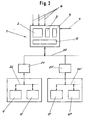
- components 9, 9 ', 9' 'and 9' '' are also controlled by control data from the central electronics 1.
- the control data of the central electronics 1 is output via a main bus 20 and a plurality of secondary data buses 22, 22 'connected to the main bus 20 each via a gateway 21, 21'.
- Several components 9, 9 ', 9' ', 9' '' are connected to each secondary data bus 22 and 22 '.
- the main bus 20 is a data bus with a higher transferable data rate than the secondary data buses 22, 22 '.
- the gateways 21, 21 ' filter out from the control data transmitted by the main data bus 20 in each case the data which only belong to the secondary data bus 22 or 22' downstream of the respective gateway 21 or 21 'and the components 9, 9' or 9 connected to them '', 9 '' 'are assigned.
- the components 9 - 9 '' 'in Figure 2 can be of the same type as the components 9 - 9' '' in Figure 1.
- a secondary bus 22 and the components 9, 9 ', 9' ', 9' '', 9 ''' connected to the main bus 20 emanating from the central electronics 1 and via a gateway 21 are included Activation data can be activated.
- Gateway 21 and components 9-9 '' '' can be of the same type as in FIGS. 1 and 2.
- main bus 20 In addition to the system of secondary bus 22 and components 9 - 9 '''' connected to the main bus 20 via the gateway 21, there are others on the main bus 20 Systems are connected and are supplied with control data or feed data into the main bus 20.
- One of these systems is an operating level 23 with a keypad 24 for manual feeding of data into the main bus 20 and a display field 25 for displaying the input data.
- climate control unit 26 which is supplied with control data via the main bus and which in turn feeds feedback data into the main bus 20.
- a third system includes a further display unit 27 with a dot matrix display field
- the central electronics 1 in FIG. 3 is simultaneously designed as a gateway and filters out the data that are to be fed to the main bus 20.
- data are also filtered out, which are fed to a further main data bus 20 'and the component system connected to it.
- This component system can have a structure similar to that of the component system connected to the main bus 20 or the component system connected to the data bus 8 in FIGS. 1 and 2.
Abstract
Description
Die Erfindung bezieht sich auf eine Ansteuereinrichtung zum Ansteuern elektrischer und/oder elektronischer Komponenten eines Kraftfahrzeugs, mit einer Zentralelektronik, der über einen Dateneingang eine Mehrzahl Daten zuleitbar sind, die in der Zentralelektronik verarbeitbar und von der über eine gemeinsame Leitung eine Mehrzahl von Komponenten Ansteuerdaten zuleitbar sind.The invention relates to a control device for controlling electrical and / or electronic components of a motor vehicle, with central electronics, to which a plurality of data can be supplied via a data input, which can be processed in the central electronics and from which a plurality of components can be supplied with control data via a common line are.
Bei einer Ansteuereinrichtung der eingangs genannten Art ist es bekannt, daß von der Zentralelektronik auf die gemeinsame Leitung in zyklischer Folge digitale Signale als binärcodierte Zahlen gegeben und die den jeweiligen als Anzeigemodule ausgebildeten Komponenten zugeordneten Daten in diese eingelesen, aufbereitet und mittels Anzeigeelementen zur Anzeige gebracht werden.In the case of a control device of the type mentioned at the outset, it is known that the central electronics pass on the common line in cyclical sequence to digital signals as binary-coded numbers and that the data associated with the respective components designed as display modules are read into them, processed and displayed by means of display elements .
Aufgabe der Erfindung ist es, eine Ansteuereinrichtung der eingangs genannten Art zu schaffen, durch die mit geringstmöglichem Aufwand eine optimale Datenversorgung erzielt wird.The object of the invention is to provide a control device of the type mentioned at the beginning, by means of which an optimal data supply is achieved with the least possible effort.
Diese Aufgabe wird erfindungsgemäß dadurch gelöst, daß die gemeinsame Leitung ein bidirektionaler Datenbus ist, über den Ausgabedaten der Komponenten, anderen Komponenten und/oder der Zentralelektronik zur Verarbeitung zuleitbar sind. Durch diese Ausgestaltung werden über den Datenbus nicht nur Ansteuerdaten von der Zentralelektronik den Komponenten zugeführt sondern über den gleichen Datenbus auch Ausgabedaten der Komponenten, wie z. B. Schaltern anderen Bereichen der Ansteuervorrichtung zugeführt.This object is achieved in that the common line is a bidirectional data bus via which the output data of the components, other components and / or the central electronics can be fed for processing. This configuration not only supplies control data from the central electronics to the components via the data bus, but also output data of the components, such as, for example, via the same data bus. B. switches other areas of the control device.
Vorzugsweise ist dabei der Datenbus ein serieller Datenbus.The data bus is preferably a serial data bus.
Besteht der Datenbus aus mindestens einer zweiadrigen Leitung, wovon eine Ader der Datenübertragung und deren andere Ader der Zuführung elektrischer Energie zu den Komponenten dient, so sind keine zusätzlichen Installationen für die Energieversorgung der Komponenten erforderlich.If the data bus consists of at least one two-wire line, of which one wire is used for data transmission and the other wire is used to supply electrical energy to the components, no additional installations are required for the energy supply of the components.
Ist die Leitung eine flexible Leitung, so kann eine Standard-Ansteuereinrichtung problemlos bei verschiedenartigen Kraftfahrzeugen eingebaut werden.If the line is a flexible line, a standard control device can easily be installed in different types of motor vehicles.
Diese universale Verwendbarkeit wird auch auch erreicht, wenn die Komponenten an beliebigen Stellen des Datenbusses ankoppelbar sind. Dies beinhaltet auch, daß je nach Wunsch eine verschiedene Anzahl und verschiedene Typen an Komponenten der Ansteuereinheit zugeordnet werden kann.This universal usability is also achieved if the components can be connected at any point on the data bus. This also means that a different number and different types of components of the control unit can be assigned as desired.
Je nach Art der Komponenten können diese ein Empfangsteil zum Empfangen der Ansteuerdaten und/oder ein Sendeteil zum Senden der Ausgabedaten aufweisen.Depending on the type of components, these can have a receiving part for receiving the control data and / or a transmitting part for sending the output data.
Da durch den Datenbus auch Daten übertragbar sind, die für mehrere Komponenten bestimmt sind, ist es von Vorteil, wenn die Komponenten eine Schnittstelle zum Datenbus, eine Anpassungselektronik zum Aufbereiten der empfangenen Ansteuerdaten und einen Ansteuerteil zum Ansteuern einer anzusteuernden Einheit aufweisen.Since the data bus can also be used to transmit data which are intended for a plurality of components, it is advantageous if the components have an interface to the data bus and an adaptation electronics unit for processing the control data received and have a control part for controlling a unit to be controlled.
Weist die Zentralelektronik eine Diagnoseschnittstelle auf, über die eine Fehler- bzw. Plausibilitätsprüfung der Zentralelektronik und/oder der Komponenten durchführbar ist, so ist auf einfache Weise eine Überprüfung sowohl der gesamten Ansteuereinrichtung als auch der einzelnen Komponenten möglich.If the central electronics has a diagnostic interface via which an error or plausibility check of the central electronics and / or the components can be carried out, then a check of both the entire control device and the individual components is possible in a simple manner.
Vorteilhafterweise können die Komponenten Anzeigemodule sein, die als anzusteuernde Einheiten Anzeigeeinheiten besitzen, die z. B. optoelektronische Anzeigeeinheiten wie LCD's oder auch Zeigerinstrumente sein können.Advantageously, the components can be display modules that have display units as control units that, for. B. optoelectronic display units such as LCDs or pointer instruments.
Auch kann die anzusteuernde Einheit eine Lichtquelle zur Beleuchtung einer weiteren anzusteuernden Einheit der Komponente sein, wobei eine Komponente mehrere anzusteuernde Einheiten besitzt.The unit to be controlled can also be a light source for illuminating a further unit of the component to be controlled, wherein a component has a plurality of units to be controlled.
Die anzusteuernden Komponenten können der verschiedensten Art sein. So ist es möglich daß die Komponenten manuell betätigbare Dateneingabeeinheiten, manuell und/oder durch Stelleinheiten betätigbare Schalter, Sensoren oder Beleuchtungseinheiten sein können.The components to be controlled can be of various types. So it is possible that the components can be manually operable data input units, manually and / or actuatable switches, sensors or lighting units.
Weist der Datenbus einen oder mehrere mit der Zentralelektronik verbundene Hauptdatenbusse und mehrere mit jedem Hauptdatenbus jeweils über ein Gateway verbundene Nebendatenbusse auf, wobei an jedem Nebendatenbus ein oder mehrere Komponenten angeschlossen sind, so brauchen nur die Hauptdatenbusse eine hohe Leistungsfähigkeit besitzen, während die Nebendatenbusse auf kostengünstige Weise nur geringe Leistungsfähigkeit besitzen müssen.If the data bus has one or more main data buses connected to the central electronics and several secondary data buses each connected to each main data bus via a gateway, with one or more components being connected to each secondary data bus, only the main data buses need to be highly efficient, while the secondary data buses are inexpensive Only need to have low performance.
Dazu ist vorzugsweise der Hauptdatenbus ein Datenbus höherer übertragbarer Datenrate als der Nebendatenbus.For this purpose, the main data bus is preferably a data bus with a higher transferable data rate than the secondary data bus.
Eine weitere Bauraum und Kosten sparende Ausbildung wird erreicht, wenn dem Dateneingang der Zentralelektronik die Daten mittels eines Datenbusses, insbesondere eines Datenbusses zuführbar sind.A further construction space and cost-saving design is achieved if the data can be fed to the data input of the central electronics by means of a data bus, in particular a data bus.
Der Datenbus und/oder der Hauptdatenbus kann ein elektrisches Signal übertragbarer Bus sein.The data bus and / or the main data bus can be an electrical signal transferable bus.
Ist der Datenbus und/oder der Hauptdatenbus ein Lichtsignale übertragender Bus, wobei insbesondere der Lichtsignale übertragende Bus Lichtleiter als Übertragungsmedium aufweist, so sind keine elektromagnetischen Störbeeinflussungen der übertragenen Signale möglich.If the data bus and / or the main data bus is a bus that transmits light signals, in particular the bus that transmits light signals has light guides as the transmission medium, then no electromagnetic interference with the transmitted signals is possible.
Auführungsbeispiele der Erfindung sind in der Zeichnung dargestellt und werden im folgenden näher beschrieben. Es zeigen
Figur 1- ein Blockschaltbild eines ersten Ausführungsbeispiels einer Ansteuereinrichtung,
Figur 2- ein Blockschaltbild eines zweiten Ausführungsbeispiels einer Ansteuereinrichtung,
- Figur 3
- ein Blockschaltbild eines dritten Ausführungsbeispiels einer Ansteuereinrichtung.
- Figure 1
- 2 shows a block diagram of a first exemplary embodiment of a control device,
- Figure 2
- 2 shows a block diagram of a second exemplary embodiment of a control device,
- Figure 3
- a block diagram of a third embodiment of a control device.
Bei allen Ausführungsbeispielen besitzt die Ansteuereinrichtung eine Zentralelektronik 1, die einen Mikrocomputer 2, ein Netzteil 3 zur Spannungsaufbereitung, Steckanschlüsse 4 sowie flüchtige und nichtflüchtige Speicher 5 aufweist.In all the exemplary embodiments, the control device has
Über Dateneingänge 6, von denen einer mit einem CAN-Bus verbunden ist sind der Zentralelektronik 1 eine Mehrzahl an Daten zuführbar. Diese Daten können z.B. von Sensoren erfaßte physikalische Größen sein. Aber auch andere Daten wie Zustandsdaten der verschiedensten Einrichtungen des Kraftfahrzeugs sind der Zentralelektronik 1 zuleitbar.A plurality of data can be supplied to the
Weiterhin besitzt die Zentralelektronik 1 eine Diagnoseschnittstelle 7, über die extern eine Fehler- bzw. Plausibilitätsüberprüfung der Zentralelektronik 1 und gegebenenfalls auch von an die Zentralelektroni 1 angeschlossenen Komponenten durchführbar ist.Furthermore, the
Wie Figur 1 zeigt, sind von der Zentralelektronik 1 über einen bidirektionalen seriellen Datenbus 8 Ansteuerdaten einer Mehrzahl von Komponenten 9, 9', 9'', 9''' zuleitbar. Über den Gleichen Datenbus 8 werden auch Ausgabedaten der einzelnen Komponenten 9, 9', 9'', 9''' sowohl anderen der Komponenten 9, 9', 9'', 9''' sowie der Zentralelektronik 1 zur Verarbeitung zugeleitet. Im Ausführungsbeispiel der Figur 1 ist die Komponente 9 ein manuell betätigbarer Schalter eines Bedienelements.
Die Komponente 9' ist ein LCD-Modul mit einer Siebensegmentanzeige 10, die von den Ansteuerdaten des Datenbusses 8 über eine Schnittstelle 11, eine Anpassungselektronik 12 sowie einen Treiber 13 ansteuerbar ist.As FIG. 1 shows, control data of a plurality of
Component 9 'is an LCD module with a seven-
Die Komponente 9''' ist eine Anzeigeeinheit, die als Zeigerinstrument ausgebildet ist. Dabei wird ein Zeigerantriebssystem 14 von den Ansteuerdaten des Datenbusses 8 über eine bidirektionale serielle Schnittstelle 15, eine mit einem Rechner verbundene Anpassungselektronik 16 und einen Treiber 17 angesteuert.The component 9 '' 'is a display unit which is designed as a pointer instrument. A
Die Anpassungselektronik 16 führt dabei eine Dämpfung der übermittelten Ansteuerdaten und eine Pulsweitenmodulation der Ansteuerwerte für das Zeigerantriebssystem 14 durch.The
Weiterhin erfolgt von der Ansteuerelektronik 16 über einen Treiber 18 eine Ansteuerung einer Lichtquelle 19 zur Beleuchtung der Anzeigeeinheit. Dabei werden von der Zentralelektronik 1 ausgegebene Einschalt- und Dimminformationen zur Ansteuerung der Lichtquelle 19 gebracht.Furthermore, the
Bei dem Ausführungsbeispiel der Figur 2 werden ebenfalls Komponenten 9, 9', 9'' und 9''' durch Ansteuerdaten der Zentralelektronik 1 angesteuert. Dabei erfolgt die Ausgabe der Ansteuerdaten der Zentralelektronik 1 über einen Hauptbus 20 und mehrere mit dem Hauptbus 20 jeweils über ein Gateway 21, 21' verbundene Nebendatenbusse 22, 22'. An jeden Nebendatenbus 22 und 22' sind mehrere Komponenten 9, 9', 9'', 9''' angeschlossen. Dabei ist der Hauptbus 20 ein Datenbus höherer übertragbarer Datenrate als die Nebendatenbusse 22, 22'.In the exemplary embodiment in FIG. 2,
Durch die Gateways 21, 21' werden aus den vom Hauptdatenbus 20 übermittelten Ansteuerdaten jeweils die Daten herausgefiltert, die nur dem dem jeweiligen Gateway 21 bzw. 21' nachgeordneten Nebendatenbus 22 bzw. 22' sowie den daran angeschlossenen Komponenten 9, 9' bzw. 9'', 9''' zugeordnet sind.The
Die Komponenten 9 - 9'''in Figur 2 können gleicher Art wie die Komponenten 9 - 9''' in Figur 1 sein.The components 9 - 9 '' 'in Figure 2 can be of the same type as the components 9 - 9' '' in Figure 1.
Bei den in Figur 3 dargestellten Ausführungsbeispiel sind über den von der Zentralelektronik 1 ausgehenden Hauptbus 20 und über ein Gateway 21 ein Nebenbus 22 und die daran angeschlossenen Komponenten 9, 9', 9'', 9''', 9'''' mit Ansteuerdaten ansteuerbar Dabei können Gateway 21 und Komponenten 9-9'''' gleicher Art sein wie in den Figuren 1 und 2.In the exemplary embodiment shown in FIG. 3, a
Außer dem über den Gateway 21 an den Hauptbus 20 angeschlossenen System aus Nebenbus 22 und Komponenten 9 - 9'''' sind an dem Hauptbus 20 weitere Systeme angeschlossen und werden mit Ansteuerdaten versorgt bzw. speisen Daten in den Hauptbus 20 ein.In addition to the system of
Eines dieser Systeme ist eine Bedienebene 23 mit einem Tastenfeld 24 zur manuellen Einspeisung von Daten in den Hauptbus 20 sowie einem Anzeigefeld 25 zur Anzeige der Eingabedaten.One of these systems is an
Ein weiteres System ist eine Klimaregeleinheit 26, der über den Hauptbus Ansteuerdaten zugeführt werden und die wiederum Rückmeldedaten in den Hauptbus 20 einspeist.Another system is a
Ein drittes System beinhaltet eine weitere Anzeigeeinheit 27 mit einem Punkt-Matrix-AnzeigefeldA third system includes a
Die Zentralelektronik 1 in Figur 3 ist gleichzeitig als Gateway ausgebildet und filtert die Daten heraus, die dem Hauptbus 20 zugeführt werden sollen.The
Darüber hinaus werden auch Daten herausgefiltert, die einem weiteren Hauptdatenbus 20' und dem daran angeschlossenen Komponentensystem zugeführt werden. Dieses Komponentensystem kann einen ähnlichen Aufbau aufweisen, wie es das an den Hauptbus 20 angeschlossene Komponentensystem oder das an den Datenbus 8 angeschlossene Komponentensystem in den Figuren 1 und 2 ist.In addition, data are also filtered out, which are fed to a further main data bus 20 'and the component system connected to it. This component system can have a structure similar to that of the component system connected to the main bus 20 or the component system connected to the data bus 8 in FIGS. 1 and 2.
Claims (23)
Applications Claiming Priority (2)
| Application Number | Priority Date | Filing Date | Title |
|---|---|---|---|
| DE19622529 | 1996-06-05 | ||
| DE19622529A DE19622529A1 (en) | 1996-06-05 | 1996-06-05 | Control device |
Publications (3)
| Publication Number | Publication Date |
|---|---|
| EP0811528A2 true EP0811528A2 (en) | 1997-12-10 |
| EP0811528A3 EP0811528A3 (en) | 2000-09-20 |
| EP0811528B1 EP0811528B1 (en) | 2003-05-21 |
Family
ID=7796197
Family Applications (1)
| Application Number | Title | Priority Date | Filing Date |
|---|---|---|---|
| EP97103507A Expired - Lifetime EP0811528B1 (en) | 1996-06-05 | 1997-03-04 | Control installation |
Country Status (3)
| Country | Link |
|---|---|
| EP (1) | EP0811528B1 (en) |
| JP (1) | JPH1084360A (en) |
| DE (2) | DE19622529A1 (en) |
Cited By (5)
| Publication number | Priority date | Publication date | Assignee | Title |
|---|---|---|---|---|
| EP0941894A3 (en) * | 1998-02-11 | 2000-09-13 | Volkswagen Aktiengesellschaft | Circuit arrangement for communication and diagnostic of a plurality of electrical components |
| WO2001005629A1 (en) * | 1999-07-15 | 2001-01-25 | International Truck Intellectual Property Company, Llc | Remote interface modules with programmable functions in vehicle multiplexing system |
| EP1017161A3 (en) * | 1998-12-29 | 2002-07-03 | SCHUNK Motorensysteme GmbH | Arrangement in a control circuit to drive the motor of an auxiliary drive in a vehicle |
| EP1669823A2 (en) | 2004-10-23 | 2006-06-14 | Continental Aktiengesellschaft | Method for adaptive vehicle control adjustment |
| WO2008062255A1 (en) * | 2006-11-21 | 2008-05-29 | Renault Trucks | Truck and bodybuilder module for this truck, method, memory and software to configure the bodybuilder module |
Families Citing this family (9)
| Publication number | Priority date | Publication date | Assignee | Title |
|---|---|---|---|---|
| DE29800732U1 (en) * | 1998-01-17 | 1999-02-18 | Eckert Hubert | Optoelectronic device |
| DE19936080A1 (en) * | 1999-07-30 | 2001-02-15 | Siemens Ag | Multiprocessor system for performing memory accesses to a shared memory and associated method |
| DE10212329B4 (en) * | 2002-03-20 | 2007-04-05 | Man Nutzfahrzeuge Ag | Electronic system for a vehicle, in particular commercial vehicle |
| AT412776B (en) * | 2002-12-09 | 2005-07-25 | Rosenbauer Int Ag | CONFIGURABLE ELECTRONIC MODULE FOR USE IN FIREMAN VEHICLES |
| DE10357762A1 (en) * | 2003-07-28 | 2005-02-24 | Wabco Gmbh & Co.Ohg | Electronic compressed air system |
| DE10341838A1 (en) | 2003-09-09 | 2005-04-28 | Siemens Ag | Method for controlling energy flows |
| DE10360881A1 (en) * | 2003-12-23 | 2005-07-28 | Knorr-Bremse Systeme für Nutzfahrzeuge GmbH | Integration of air suspension electronics in an electronic air treatment system |
| DE10360875B4 (en) * | 2003-12-23 | 2008-03-27 | Knorr-Bremse Systeme für Nutzfahrzeuge GmbH | Integration of air suspension electronics in an electronic brake system |
| DE102004005680A1 (en) * | 2004-02-05 | 2005-08-25 | Bayerische Motoren Werke Ag | Device and method for controlling control units in a vehicle electrical system of a motor vehicle |
Citations (2)
| Publication number | Priority date | Publication date | Assignee | Title |
|---|---|---|---|---|
| US5079759A (en) * | 1989-08-30 | 1992-01-07 | Mazda Motor Corporation | Multiplex transmission system for vehicles having a failure diagnosis function |
| FR2726411A1 (en) * | 1994-10-26 | 1996-05-03 | Peugeot | CURRENT CURRENT INFORMATION COMMUNICATION SYSTEM, IN PARTICULAR FOR A MOTOR VEHICLE |
Family Cites Families (5)
| Publication number | Priority date | Publication date | Assignee | Title |
|---|---|---|---|---|
| DE3103884A1 (en) * | 1981-02-05 | 1982-09-02 | Robert Bosch Gmbh, 7000 Stuttgart | REMOTE CONTROL SYSTEM FOR SELECTIVE CONTROL OF CONSUMERS |
| JP2904296B2 (en) * | 1990-03-30 | 1999-06-14 | マツダ株式会社 | Multiplex transmission equipment for vehicles |
| DE4322249A1 (en) * | 1992-10-23 | 1994-04-28 | Marquardt Gmbh | Bus switch |
| DE4413977C2 (en) * | 1994-04-21 | 1996-02-22 | Knorr Bremse Systeme | Cable junction of a data bus for connecting electronic control units in passenger cars and commercial vehicles |
| DE4440178A1 (en) * | 1994-11-10 | 1996-05-15 | Csb Syst Software Entwicklung | Integration medium for collecting, processing, transferring and archiving an individual's accessible medical data, which are available at any time |
-
1996
- 1996-06-05 DE DE19622529A patent/DE19622529A1/en not_active Ceased
-
1997
- 1997-03-04 EP EP97103507A patent/EP0811528B1/en not_active Expired - Lifetime
- 1997-03-04 DE DE59710104T patent/DE59710104D1/en not_active Expired - Fee Related
- 1997-06-02 JP JP9143671A patent/JPH1084360A/en active Pending
Patent Citations (2)
| Publication number | Priority date | Publication date | Assignee | Title |
|---|---|---|---|---|
| US5079759A (en) * | 1989-08-30 | 1992-01-07 | Mazda Motor Corporation | Multiplex transmission system for vehicles having a failure diagnosis function |
| FR2726411A1 (en) * | 1994-10-26 | 1996-05-03 | Peugeot | CURRENT CURRENT INFORMATION COMMUNICATION SYSTEM, IN PARTICULAR FOR A MOTOR VEHICLE |
Cited By (8)
| Publication number | Priority date | Publication date | Assignee | Title |
|---|---|---|---|---|
| EP0941894A3 (en) * | 1998-02-11 | 2000-09-13 | Volkswagen Aktiengesellschaft | Circuit arrangement for communication and diagnostic of a plurality of electrical components |
| EP1017161A3 (en) * | 1998-12-29 | 2002-07-03 | SCHUNK Motorensysteme GmbH | Arrangement in a control circuit to drive the motor of an auxiliary drive in a vehicle |
| WO2001005629A1 (en) * | 1999-07-15 | 2001-01-25 | International Truck Intellectual Property Company, Llc | Remote interface modules with programmable functions in vehicle multiplexing system |
| US6272402B1 (en) | 1999-07-15 | 2001-08-07 | Navistar International Transportation Corp. | Remote interface modules with programmable functions |
| EP1669823A2 (en) | 2004-10-23 | 2006-06-14 | Continental Aktiengesellschaft | Method for adaptive vehicle control adjustment |
| EP1669823A3 (en) * | 2004-10-23 | 2006-09-13 | Continental Aktiengesellschaft | Method for adaptive vehicle control adjustment |
| WO2008062255A1 (en) * | 2006-11-21 | 2008-05-29 | Renault Trucks | Truck and bodybuilder module for this truck, method, memory and software to configure the bodybuilder module |
| CN101573255B (en) * | 2006-11-21 | 2011-11-16 | 雷诺卡车公司 | Truck and bodybuilder module for this truck, method, memory and software to configure the bodybuilder module |
Also Published As
| Publication number | Publication date |
|---|---|
| JPH1084360A (en) | 1998-03-31 |
| DE19622529A1 (en) | 1997-12-11 |
| EP0811528B1 (en) | 2003-05-21 |
| DE59710104D1 (en) | 2003-06-26 |
| EP0811528A3 (en) | 2000-09-20 |
Similar Documents
| Publication | Publication Date | Title |
|---|---|---|
| EP0811528B1 (en) | Control installation | |
| DE19600644C1 (en) | Automobile function module circuit | |
| DE102009005651B4 (en) | Device for controlling a variety of engines | |
| EP1582040A1 (en) | Device for a two-wire line terminal | |
| DE19525180C5 (en) | Electronic control unit for a motor vehicle with data networks and immobilizer | |
| DE3609098A1 (en) | Vehicle heating system, in particular vehicle heating system which can be operated independently of the engine | |
| EP0393233A2 (en) | Signal transmitting system | |
| DD297737A5 (en) | CABLING SYSTEM FOR VEHICLES | |
| EP0773139A2 (en) | Control and monitoring device for the functions of a trailer | |
| DE10255301A1 (en) | Selectively operating vehicle trailer lights involves generating control signals in vehicle, sending to trailer, switching voltage source in trailer with received signals to provide operating voltage | |
| DE4344904A1 (en) | Connection of activators and sensors to field bus | |
| DE102005044004B3 (en) | Actuator for a mechanical component and control device | |
| EP0736419A2 (en) | Device for the operation of at least one vehicle-mounted apparatus | |
| DE10214185A1 (en) | PC arrangement for visualization, diagnostic and expert systems for monitoring and control or regulation of high-voltage supply units of electrostatic filters | |
| DE4417369A1 (en) | Device for operating stepper motors | |
| EP0657990B1 (en) | Stepper motors driving device | |
| EP0249160A1 (en) | Industrial sewing machine | |
| EP0639706A2 (en) | System for the control of an actuator adjusting the air supply of a vehicle engine | |
| DE19962533B4 (en) | Device for checking the functioning of a distance control device of a motor vehicle | |
| DE102019132428A1 (en) | Function-oriented electronics architecture | |
| DE10004020A1 (en) | Vehicle wiring | |
| DE3823788A1 (en) | Arrangement for the connection of wall switches in installation systems | |
| EP0707249A2 (en) | Device for the control of mechanical or electro-mechanical actuators | |
| DE10212329B4 (en) | Electronic system for a vehicle, in particular commercial vehicle | |
| DE3742617A1 (en) | ELECTRICAL CIRCUIT ARRANGEMENT |
Legal Events
| Date | Code | Title | Description |
|---|---|---|---|
| PUAI | Public reference made under article 153(3) epc to a published international application that has entered the european phase |
Free format text: ORIGINAL CODE: 0009012 |
|
| AK | Designated contracting states |
Kind code of ref document: A2 Designated state(s): DE FR GB |
|
| PUAL | Search report despatched |
Free format text: ORIGINAL CODE: 0009013 |
|
| AK | Designated contracting states |
Kind code of ref document: A3 Designated state(s): DE FR GB |
|
| 17P | Request for examination filed |
Effective date: 20010317 |
|
| 17Q | First examination report despatched |
Effective date: 20010625 |
|
| RAP1 | Party data changed (applicant data changed or rights of an application transferred) |
Owner name: SIEMENS AKTIENGESELLSCHAFT |
|
| GRAG | Despatch of communication of intention to grant |
Free format text: ORIGINAL CODE: EPIDOS AGRA |
|
| GRAG | Despatch of communication of intention to grant |
Free format text: ORIGINAL CODE: EPIDOS AGRA |
|
| GRAH | Despatch of communication of intention to grant a patent |
Free format text: ORIGINAL CODE: EPIDOS IGRA |
|
| GRAH | Despatch of communication of intention to grant a patent |
Free format text: ORIGINAL CODE: EPIDOS IGRA |
|
| GRAA | (expected) grant |
Free format text: ORIGINAL CODE: 0009210 |
|
| AK | Designated contracting states |
Designated state(s): DE FR GB |
|
| REG | Reference to a national code |
Ref country code: GB Ref legal event code: FG4D Free format text: NOT ENGLISH |
|
| REF | Corresponds to: |
Ref document number: 59710104 Country of ref document: DE Date of ref document: 20030626 Kind code of ref document: P |
|
| GBT | Gb: translation of ep patent filed (gb section 77(6)(a)/1977) | ||
| ET | Fr: translation filed | ||
| PLBE | No opposition filed within time limit |
Free format text: ORIGINAL CODE: 0009261 |
|
| STAA | Information on the status of an ep patent application or granted ep patent |
Free format text: STATUS: NO OPPOSITION FILED WITHIN TIME LIMIT |
|
| 26N | No opposition filed |
Effective date: 20040224 |
|
| PGFP | Annual fee paid to national office [announced via postgrant information from national office to epo] |
Ref country code: GB Payment date: 20090325 Year of fee payment: 13 |
|
| PGFP | Annual fee paid to national office [announced via postgrant information from national office to epo] |
Ref country code: DE Payment date: 20090320 Year of fee payment: 13 |
|
| PGFP | Annual fee paid to national office [announced via postgrant information from national office to epo] |
Ref country code: FR Payment date: 20090312 Year of fee payment: 13 |
|
| GBPC | Gb: european patent ceased through non-payment of renewal fee |
Effective date: 20100304 |
|
| REG | Reference to a national code |
Ref country code: FR Ref legal event code: ST Effective date: 20101130 |
|
| PG25 | Lapsed in a contracting state [announced via postgrant information from national office to epo] |
Ref country code: FR Free format text: LAPSE BECAUSE OF NON-PAYMENT OF DUE FEES Effective date: 20100331 |
|
| PG25 | Lapsed in a contracting state [announced via postgrant information from national office to epo] |
Ref country code: DE Free format text: LAPSE BECAUSE OF NON-PAYMENT OF DUE FEES Effective date: 20101001 |
|
| PG25 | Lapsed in a contracting state [announced via postgrant information from national office to epo] |
Ref country code: GB Free format text: LAPSE BECAUSE OF NON-PAYMENT OF DUE FEES Effective date: 20100304 |