EP0811843B1 - Fluid testing sensor for use in dispensing instruments - Google Patents
Fluid testing sensor for use in dispensing instruments Download PDFInfo
- Publication number
- EP0811843B1 EP0811843B1 EP97108865A EP97108865A EP0811843B1 EP 0811843 B1 EP0811843 B1 EP 0811843B1 EP 97108865 A EP97108865 A EP 97108865A EP 97108865 A EP97108865 A EP 97108865A EP 0811843 B1 EP0811843 B1 EP 0811843B1
- Authority
- EP
- European Patent Office
- Prior art keywords
- sensor
- edge
- lid
- base
- foil
- Prior art date
- Legal status (The legal status is an assumption and is not a legal conclusion. Google has not performed a legal analysis and makes no representation as to the accuracy of the status listed.)
- Expired - Lifetime
Links
- 238000012360 testing method Methods 0.000 title claims abstract description 74
- 239000012530 fluid Substances 0.000 title claims abstract description 21
- 239000011888 foil Substances 0.000 claims abstract description 70
- 239000000463 material Substances 0.000 claims description 27
- 239000003153 chemical reaction reagent Substances 0.000 claims description 15
- 239000008280 blood Substances 0.000 description 33
- 210000004369 blood Anatomy 0.000 description 33
- WQZGKKKJIJFFOK-GASJEMHNSA-N Glucose Natural products OC[C@H]1OC(O)[C@H](O)[C@@H](O)[C@@H]1O WQZGKKKJIJFFOK-GASJEMHNSA-N 0.000 description 24
- 239000008103 glucose Substances 0.000 description 24
- 239000002274 desiccant Substances 0.000 description 16
- 230000002093 peripheral effect Effects 0.000 description 6
- 238000012545 processing Methods 0.000 description 6
- 230000002411 adverse Effects 0.000 description 5
- 238000012544 monitoring process Methods 0.000 description 4
- 239000011324 bead Substances 0.000 description 2
- 230000015572 biosynthetic process Effects 0.000 description 2
- 238000004891 communication Methods 0.000 description 2
- NOESYZHRGYRDHS-UHFFFAOYSA-N insulin Chemical compound N1C(=O)C(NC(=O)C(CCC(N)=O)NC(=O)C(CCC(O)=O)NC(=O)C(C(C)C)NC(=O)C(NC(=O)CN)C(C)CC)CSSCC(C(NC(CO)C(=O)NC(CC(C)C)C(=O)NC(CC=2C=CC(O)=CC=2)C(=O)NC(CCC(N)=O)C(=O)NC(CC(C)C)C(=O)NC(CCC(O)=O)C(=O)NC(CC(N)=O)C(=O)NC(CC=2C=CC(O)=CC=2)C(=O)NC(CSSCC(NC(=O)C(C(C)C)NC(=O)C(CC(C)C)NC(=O)C(CC=2C=CC(O)=CC=2)NC(=O)C(CC(C)C)NC(=O)C(C)NC(=O)C(CCC(O)=O)NC(=O)C(C(C)C)NC(=O)C(CC(C)C)NC(=O)C(CC=2NC=NC=2)NC(=O)C(CO)NC(=O)CNC2=O)C(=O)NCC(=O)NC(CCC(O)=O)C(=O)NC(CCCNC(N)=N)C(=O)NCC(=O)NC(CC=3C=CC=CC=3)C(=O)NC(CC=3C=CC=CC=3)C(=O)NC(CC=3C=CC(O)=CC=3)C(=O)NC(C(C)O)C(=O)N3C(CCC3)C(=O)NC(CCCCN)C(=O)NC(C)C(O)=O)C(=O)NC(CC(N)=O)C(O)=O)=O)NC(=O)C(C(C)CC)NC(=O)C(CO)NC(=O)C(C(C)O)NC(=O)C1CSSCC2NC(=O)C(CC(C)C)NC(=O)C(NC(=O)C(CCC(N)=O)NC(=O)C(CC(N)=O)NC(=O)C(NC(=O)C(N)CC=1C=CC=CC=1)C(C)C)CC1=CN=CN1 NOESYZHRGYRDHS-UHFFFAOYSA-N 0.000 description 2
- 238000004519 manufacturing process Methods 0.000 description 2
- 238000000034 method Methods 0.000 description 2
- 102000004877 Insulin Human genes 0.000 description 1
- 108090001061 Insulin Proteins 0.000 description 1
- 230000009172 bursting Effects 0.000 description 1
- 230000000295 complement effect Effects 0.000 description 1
- 230000001419 dependent effect Effects 0.000 description 1
- 230000000994 depressogenic effect Effects 0.000 description 1
- 206010012601 diabetes mellitus Diseases 0.000 description 1
- 229940079593 drug Drugs 0.000 description 1
- 239000003814 drug Substances 0.000 description 1
- 238000009459 flexible packaging Methods 0.000 description 1
- 230000002401 inhibitory effect Effects 0.000 description 1
- 229940125396 insulin Drugs 0.000 description 1
- 230000013011 mating Effects 0.000 description 1
- 238000004806 packaging method and process Methods 0.000 description 1
- 239000008188 pellet Substances 0.000 description 1
- 239000000843 powder Substances 0.000 description 1
- 238000009877 rendering Methods 0.000 description 1
- 238000007789 sealing Methods 0.000 description 1
- 238000010998 test method Methods 0.000 description 1
- 238000012956 testing procedure Methods 0.000 description 1
Images


Classifications
-
- B—PERFORMING OPERATIONS; TRANSPORTING
- B01—PHYSICAL OR CHEMICAL PROCESSES OR APPARATUS IN GENERAL
- B01L—CHEMICAL OR PHYSICAL LABORATORY APPARATUS FOR GENERAL USE
- B01L99/00—Subject matter not provided for in other groups of this subclass
-
- G—PHYSICS
- G01—MEASURING; TESTING
- G01N—INVESTIGATING OR ANALYSING MATERIALS BY DETERMINING THEIR CHEMICAL OR PHYSICAL PROPERTIES
- G01N33/00—Investigating or analysing materials by specific methods not covered by groups G01N1/00 - G01N31/00
- G01N33/48—Biological material, e.g. blood, urine; Haemocytometers
- G01N33/483—Physical analysis of biological material
- G01N33/487—Physical analysis of biological material of liquid biological material
- G01N33/4875—Details of handling test elements, e.g. dispensing or storage, not specific to a particular test method
-
- Y—GENERAL TAGGING OF NEW TECHNOLOGICAL DEVELOPMENTS; GENERAL TAGGING OF CROSS-SECTIONAL TECHNOLOGIES SPANNING OVER SEVERAL SECTIONS OF THE IPC; TECHNICAL SUBJECTS COVERED BY FORMER USPC CROSS-REFERENCE ART COLLECTIONS [XRACs] AND DIGESTS
- Y10—TECHNICAL SUBJECTS COVERED BY FORMER USPC
- Y10T—TECHNICAL SUBJECTS COVERED BY FORMER US CLASSIFICATION
- Y10T436/00—Chemistry: analytical and immunological testing
- Y10T436/11—Automated chemical analysis
- Y10T436/110833—Utilizing a moving indicator strip or tape
-
- Y—GENERAL TAGGING OF NEW TECHNOLOGICAL DEVELOPMENTS; GENERAL TAGGING OF CROSS-SECTIONAL TECHNOLOGIES SPANNING OVER SEVERAL SECTIONS OF THE IPC; TECHNICAL SUBJECTS COVERED BY FORMER USPC CROSS-REFERENCE ART COLLECTIONS [XRACs] AND DIGESTS
- Y10—TECHNICAL SUBJECTS COVERED BY FORMER USPC
- Y10T—TECHNICAL SUBJECTS COVERED BY FORMER US CLASSIFICATION
- Y10T436/00—Chemistry: analytical and immunological testing
- Y10T436/11—Automated chemical analysis
- Y10T436/112499—Automated chemical analysis with sample on test slide
Definitions
- the present invention generally relates to a fluid monitoring sensor and, more particularly, to a new and improved sensor used in analyzing blood glucose or other analytes contained therein that is configured so that as the sensor is being ejected from a cavity of a sensor pack loaded into a dispensing instrument, a shard of the sensor pack material will not be severed that could otherwise interfere with the proper operation of the dispensing instrument.
- sensors are used to test a sample of blood.
- Such a sensor may have a generally flat, rectangular shape and is formed from two pieces of mated plastic, a base portion and a lid portion.
- the sensor has a front or testing end and a rear end.
- the sensor contains biosensing or reagent material that will react with blood glucose.
- the testing end of the sensor is adapted to be placed into the fluid being tested, for example, blood that has accumulated on a person's finger after the finger has been pricked.
- a sufficient amount of fluid to be tested is drawn into a capillary channel that extends between the mated pieces of the sensor from the testing end to the reagent material by capillary action.
- the fluid then chemically reacts with the reagent material in the sensor with the result that an electrical signal indicative of the blood glucose level in the blood being tested is supplied to contacts located on the exterior of the sensor.
- the sensors In order to couple the electrical signals produced at the sensor contacts to monitoring equipment, the sensors need to be inserted into sensor holders prior to the sensor testing end being placed into the , fluid being tested.
- the holders have corresponding mating contacts that become coupled to the contacts on the sensor when the sensor is inserted into the holder. Consequently, the holders act as an interface between the sensor and monitoring equipment that accumulates and/or analyzes the test results.
- the sensors Prior to being used, the sensors need to be maintained at an appropriate humidity level so as to insure the integrity of the reagent materials in the sensor.
- Sensors can be packaged individually in tear-away packages so that they can be maintained at the proper humidity level.
- blister type packaging methods could be used.
- the packages can include desiccant material to maintain the proper humidity or desiccate level in the package.
- the package In order for a person to use an individual sensor for testing blood glucose, the package must be opened by tearing the seal. Alternatively, some packages require the user to exert force against one side of the package resulting in the sensor bursting or rupturing the foil on the other side. As can be appreciated, the opening of these packages can be difficult. Moreover, once the package is opened, the user needs to be sure that the sensor is not damaged or contaminated as it is being placed into the sensor holder and used to test the blood sample.
- Sensor dispensing instruments have been developed for dispensing individual ones of the sensors to a sensing position from within a sensor pack loaded into the sensor dispensing instrument.
- One such type of sensor pack includes a generally circular shaped base portion in which is formed sensor retaining cavities or depressions. Each of the sensor retaining cavities is adapted to receive one of the sensors and is in fluid communication with a corresponding desiccant cavity in which is disposed desiccant material. The desiccant material is placed in the cavity to insure that the corresponding sensor cavity is maintained at an appropriate humidity or desiccate level so that the reagent material in the sensors will not be adversely affected prior to the sensors being used.
- a foil is heat sealed onto the base portion about the entire outer peripheral edge of the base portion and about the entire perimeter of each set of sensor retaining and desciccant cavities to seal the sensor retaining cavities and the desiccant cavities.
- the circular type sensor pack can be loaded in a sensor dispensing instrument that has a feeding mechanism.
- the feeding mechanism When the feeding mechanism is actuated or moved forward toward a testing end of the instrument, one of the sensors in the sensor pack is ejected from the sensor pack and placed into a sensing position.
- a driver on which is mounted a knife blade moves toward one of the sensor cavities in the sensor pack that is positioned in alignment with the knife blade as the feeding mechanism is moved forward.
- the knife blade pierces the foil covering that sensor cavity and engages the rear end of the sensor disposed in that cavity.
- the knife blade further severs the foil covering the sensor cavity and forces or ejects the sensor out from the sensor cavity causing a front biased edge of the sensor to burst through the outer foil covering the sensor cavity.
- the sensor travels along a sloped support wall at the base of the sensor cavity so that as the sensor is advanced by the knife blade, the sensor will avoid being forced into the heat seal that affixes the foil to the base portion of the sensor pack.
- the force required to drive the sensor through the foil is in part determined by the specific geometry of the front end of the sensor.
- the sensor is guided into its testing position with the testing end of the sensor projecting out from the testing end of the instrument.
- contacts in the instrument become mated with corresponding contacts on the sensor.
- the sensor dispensing instrument may include a microprocessor or other data processing circuitry that is electrically coupled to the instrument contacts so that data obtained from the sensor when it is inserted into blood being tested can be processed. The processed data then can be displayed on a screen of the instrument or stored for use in other analyzing equipment.
- the feed mechanism can be used to eject the used sensor from the testing end of the dispensing instrument. Thereafter, the feed mechanism is retracted to a standby position resulting in the sensor pack being rotated so that another sensor cavity is in alignment with the knife blade on the driver mechanism and another sequence can be initiated to eject another one of the sensors from the sensor pack.
- a sensor dispensing instrument is disclosed in EP 0 732 590 A2 , which is prior art according to Art. 54(3), 54(4) EPC for the present patent application.
- the senor is from mated plastic lid and base portions between which is sandwiched the reagent material.
- the testing end profile of both the lid and base portions of the sensor need to be configured such that the sensor will burst with a minimum of force through the thin foil that overlies the sensor cavities of the sensor pack.
- the testing end edges of the lid and base portions may result in the tearing of a shard of foil (a little piece of foil that separates from the foil overlying the sensor cavities) as the sensor is being ejected through the foil from a sensor cavity.
- the severed shard of foil either may block the capillary channel inhibiting the fluid to be tested from flowing into the sensor or may short circuit the instrument or sensor contacts thereby rendering the instrument inoperative.
- a shard of foil tends to be caused by the configuration and spatial relationship of the mated plastic pieces (i.e., the lid and base) at the testing end of the sensor.
- the lid and base are not sufficiently offset longitudinally (i.e., in the direction from the rear end to the front end of the sensor) with respect to each other, the base and lid creates two cutting edges so that the foil tends to be cut by a scissoring like action rather than being severed. This scissoring action tends to result in a small piece or shard of the foil be severed from the foil overlying the sensor cavity.
- the angle of the lid and/or base with respect to the transverse axis of the sensor also can contribute to the formation of a shard of foil.
- a shard of foil may be torn from the foil when the testing ends of the lid and base are biased at a continuous (usually obtuse angle) with respect to the transverse axis of the sensor.
- a continuous (usually obtuse angle) with respect to the transverse axis of the sensor.
- US 5,510,266 discloses a method and apparatus of handling multiple sensors in a glucose monitoring instrument system.
- a sensor dispending instrument includes a sensor magazine that contains a plurality of blood glucose sensors disposed in sensor slots.
- the front and rear walls of the sensor magazine are sealed with burst foils so as to seal the sensor slots.
- a sensor push rod is pushed forward resulting in the push rod piercing the rear burst foil and engaging a sensor in one of the sensor slots to thereby push the sensor out through the front burst foil and into a testing position.
- the sensors are generally flat, rectangular in shape extending from a front or testing end to a rear or contact end.
- the front end has oppositely extending chamfered edges and so that the front end is adapted to puncture the front burst foil when forced out of the sensor slots by the push rod.
- an object of the present inventtion is to provide a new and improved sensor used in analyzing blood glucose or other analytes contained therein that is adapted to be ejected from a sensor pack loaded in a sensor dispensing instrument.
- Other objects of the present invention are to provide a new and improved blood glucose sensor having a front testing end configured to facilitate the ejection of the sensor from the sensor pack; to provide a new and improved blood glucose sensor formed from mated base and lid pieces of plastic, the front testing end of which is configured to minimize producing shards of foil as the sensor is being ejected from a sensor cavity in a sensor pack; and to provide a new and improved blood glucose sensor formed from mated base and lid pieces of plastic, the front edges of which base and lid being positioned relative to each other and having specific biased angles so as to minimize the production of shards of foil as the sensor is being ejected from a sensor cavity in a sensor pack, but at the same time enabling the sensor to be ejected from the sensor cavity with a
- the present invention is embodied in a sensor that is adapted to be stored within a sensor cavity of a sensor pack to be used in a sensor dispensing instrument.
- the sensor has a generally flat, rectangular shape and is formed of two mated pieces of plastic material, one forming a base of the sensor and the other forming a lid of the sensor.
- the sensor has a longitudinal axis extending from a front testing end to a rear ejection end with a transverse axis extending between side edges of the sensor perpendicularly to the longitudinal axis. Biosensing or reagent material that will react with blood glucose is disposed within the sensor between the base and lid.
- the testing end of the sensor is adapted to be placed into the fluid being tested so that a sufficient amount of the fluid is drawn by capillary action into a capillary channel that extends between the mated pieces of the sensor from the testing end to the reagent material.
- the fluid chemically reacts with the reagent material in the sensor with the result that an electrical signal indicative of the blood glucose level in the blood being tested is supplied to contacts located on the sensor.
- the rear, ejector end of the sensor has a notch that is engaged by a knife blade of the sensor dispensing instrument as the sensor is being ejected from the sensor cavity of the sensor pack.
- the front testing edge of the lid overhangs the front testing edge of the base of the sensor so that the front testing edge of the lid is sufficiently forward in the longitudinal direction of the front testing edge of the base that the testing end essentially has a single cutting edge.
- One side edge of the sensor adjacent the front edges of the base and lid is beveled at about a 25° angle. The front edge of both the base and the lid are biased with respect to the transverse axis of the sensor.
- the front edge of the base extends from the beveled side portion across the entire remaining width of the sensor at an angle of approximately 10° with respect to transverse axis.
- the front edge of the lid also is angled with respect to the transverse axis of the sensor, it has two different angular portions.
- the first major portion of the front lid edge extends from the beveled side portion across a significant portion of the width of the sensor at an angle of about 15° with respect to the transverse axis of the sensor.
- the other portion of the front edge of the lid extends at an angle of about 25° with respect to the transverse axis of the sensor so that a relatively pointed tip at the side edge opposite from the beveled side portion is formed to pierce the foil overlying the sensor cavity in which the sensor is disposed as the sensor is being ejected from the cavity.
- the overhang of the lid over the base of the sensor and the particular biased angles for the front edges of the lid and base of the sensor enables the sensor to pierce the foil that overlies the sensor cavity from which the sensor is being ejected by a force that is within acceptable limits.
- the particular configuration of the overhang of the lid over the base and the biased angles of the front edges of the base and lid insures that a shard of foil is not ripped from the foil portion of the sensor pack as the sensor is being ejected from the sensor cavity in which the sensor is stored.
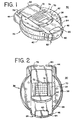
- a blood glucose sensor dispensing instrument 30 ( FIGS. 1-4 ) that is adapted to have loaded therein a sensor pack 32 ( FIGS. 5-8 ) in which is disposed a plurality of sensors or testing elements 34 ( FIGS. 9-10 ) embodying the present invention.
- the sensor dispensing instrument 30 includes an outer housing 36 having an upper case 38 and a lower case 40.
- the upper case 38 is pivotable with respect to the lower case 40 in a clam shell fashion so that the sensor pack 32 can be positioned within the housing 36.
- a slide actuator 42 on the upper case 38 of the housing 36 manually is slid from a standby position ( FIGS.
- the slide actuator 42 also can be moved to place the sensor dispensing instrument 30 in a data processing or display mode.
- the movement of the slide actuator 42 towards its testing position forces a knife blade assembly 48 (diagrammatically shown in FIG. 11 ) to move with respect to the sensor pack 32.
- a knife blade 50 on the knife blade assembly 48 pierces a portion of a foil 52 covering one of a plurality of sensor cavities 54A-J, such as the cavity 54J, in a base portion 56 of the sensor pack 32 that is in alignment with the knife blade 50.
- the sensor 34 disposed in the cavity 54J is engaged by the knife blade 50 resulting in the knife blade 50 further severing the foil 52 covering the sensor cavity 54J and forcing or ejecting the sensor 34 out from the sensor cavity 54J.
- the sensor 34 After the sensor 34 has been completely ejected from the sensor cavity 54J, the sensor 34 becomes lodged in its testing position projecting out from the testing end 46 of the sensor dispensing instrument 30 ( FIG. 4 ). Contacts 58 on the sensor 34 are coupled within the housing 36 to electronic circuitry (not shown) disposed in the upper case 38.
- the circuitry may include a microprocessor or the like for processing, storing and/or displaying data generated during a blood glucose test procedure.
- the sensor 34 is released from the housing 36 and the slide actuator 42 is manually retracted in the opposite direction towards its standby position adjacent the rear end 44 of the upper case 38.
- the retraction of the slide actuator 42 to its standby position results in the rotation of the sensor pack 32 so that the next one of sensor cavities 54A-J is positioned in alignment with the knife blade 50 enabling the sensor 34 in the next sensor cavity 54I to be used in the next blood glucose testing procedure.
- the upper case 38 and the lower case 40 of the sensor dispensing housing 36 are complementary, generally round in shape containers that are adapted to be pivoted with respect to each other.
- the upper case 38 and the lower case 40 are maintained in their closed configuration as shown in FIGS. 1-4 by a latch 60 that is pivotally mounted in a front or testing section 62 of the lower case 40.
- the latch 60 When the latch 60 is pivoted upwardly, it clips into a recess 64 in a front or testing end section 66 of the upper case 38 thereby securing the upper case 38 and the lower case 40 in their closed configuration.
- the upper case 34 has a recess 68 that extends in its exterior upper wall 70 from the front section 66 to adjacent the rear end 44.
- the slide actuator 42 is adapted to be mounted within the recess 68 so that it can be slid forward toward the front end 46 or retracted toward the rear end 44.
- a slide latch 72 is mounted on the slide actuator 42 and includes a plurality of raised nubs 74 that provides a surface facilitating the movement of the slide latch 72 and the slide actuator 42 by a person using the sensor dispensing instrument 30.
- the movement of the slide latch 72 determines in which of two operating modes the dispensing instrument 30 is placed. In a first or testing mode, the slide latch 72 is positioned as shown in FIGS. 1, 2 and 4 . In a second or data processing mode, the slide latch 72 is slid laterally with respect to the slide actuator 42.
- the knife blade assembly 48 When the slide latch 72 is in its testing mode position, the knife blade assembly 48 is moved with respect to the foil 52 and with respect to one of the sensors 34 within the sensor pack 32 as the slide actuator 42 is moved toward the testing end 46. On the other hand, the knife blade assembly 48 is not moved as the slide actuator 42 is moved toward the testing end 46 when the slide latch 72 is slid laterally with respect to the slide actuator 42 for placing the dispensing instrument 30 into its data processing mode. Instead, data and other information concerning the status of the dispensing instrument 30 and the test being performed is visible through a lens 76 in the recess 68 near the rear end 46 of the upper case 34 when the slide actuator 42 is moved toward the front end 46 of the upper case 38 (see generally FIG. 4 ).
- buttons 78 and 80 that are disposed in the rear end 44.
- the buttons 78 and 80 can be depressed to view and/or input the testing information that will be displayed.
- the sensors 34 that are to be used in the dispensing instrument 30 are packaged in the sensor pack 32 which is formed of the circularly shaped base portion 56 and the correspondingly configured foil 52.
- the sensor cavities 54A-J are formed as depressions in the base portion 56 with each of the sensor cavities 54A-J adapted to house one of the sensors 34.
- each of the sensor cavities 54A-J has a bottom support wall 82 that extends from an inner end 84 to an outer end 86 of the sensor cavity 54A.
- the support wall 82 is inclined or sloped slightly upward as it extends from the inner end 84 to the outer end 86.
- Each of the sensor cavities 54A-J is in fluid communication with a corresponding one of desiccant cavities 88A-J.
- Each of the desiccant cavities 88A-J is formed of a small depression in the base portion 56 adjacent the corresponding one of the sensor cavities 54A-J.
- Desiccant material is disposed in the desiccant cavities 88A-J in order to insure that the sensor cavities 54A-J are maintained at an appropriate humidity level so that the reagent material in the sensor 34 disposed in the particular sensor cavity 54A-J is not adversely affected prior to being used.
- the desiccant material might be in the form of a small bag or round bead of material or any other form that can be readily disposed in the desiccant cavities 88A-J.
- the amount of such desiccant material placed in each of the desiccant cavities 88A-J will be dependent on the amount that is required to maintain the sensor cavities 54A-J in a desiccate state.
- One type of desiccant material that could be used is sold under the trademark NATRASORB and is available in powder, pellet and bead forms.
- Notches 90 are formed along the outer peripheral edge of the base portion 56.
- notches 92 along the outer peripheral edge of the foil 52 will be in alignment with the notches 90 to thereby form an integral series of notches along the outer peripheral edge of the sensor pack 32.
- Each of the notches formed by the notches 90 and 92 is associated with one of the sensor cavities 54A-J in the base portion 56 such that when the sensor pack 32 is mounted within the dispensing instrument 30, the sensor pack 32 can be rotated so that each one of the sensor cavities 54A-J will sequentially be placed into proper alignment with the knife blade 50 on the knife blade assembly 48 so that the individual ones of the sensors 34 within the sensor cavities 54A-J can be ejected from those sensor cavities 54A-J.
- the foil 52 is adapted to cover the top of the base portion 56 and be affixed to the base portion 56 by heat sealing along the entire outer peripheral edge of the foil 52 to the outer peripheral edge of the base portion 56.
- the foil 52 also is heat sealed about the entire perimeter of each set of the sensor retaining cavities 54A-J and the desciccant cavities 88A-J to seal the sensor retaining cavities 54A-J and the desiccant cavities 88A-J such that the individual sensors 34 are maintained in a desiccated state and isolated from each other.
- the opening of one of the sensor cavities 54A-J will not affect the desiccated state of any of the other sensor cavities 54A-J.
- the foil 52 may be made of any material that will adequately seal the sensor cavities 54A-J and the desiccant cavities 88A-J while providing a material that will can be really severed by the knife blade 50 and pierced by the sensor 34 as it is being pushed out from the sensor cavities 54A-J.
- One type of foil that can be used for the foil 52 is AL-191-01 foil distributed by Alusuisse Flexible Packaging, Inc.
- the base portion 56 of the sensor pack 32 includes a label area 94 on its underside inwardly of the sensor cavities 54A-J.
- a conductive label 96 is positioned in this label area 94 and provides calibration and production information that can be sensed when the sensor pack 32 is loaded into the sensor dispensing instrument 30.
- the sensor pack 32 is adapted to house ten sensors 34 with one of the ten sensors 34 in each of the sensor cavities 54A-J.
- each of the sensors 34 has a generally flat, rectangular shape, is formed of mated plastic pieces, i.e., a lid 98 and a base 100, and extends from a front or testing end 102 to a rear or ejection end 104.
- Each of the sensors 34 is provided with a capillary channel that extends from the front, testing end 102 of the sensor 34 to biosensing or reagent material disposed between the mated pieces 98 and 100 of the sensor 34.
- the testing end 102 of the sensor 34 When the testing end 102 of the sensor 34 is placed into fluid (for example, blood that is accumulated on a person's finger after the finger has been pricked), a portion of the fluid is drawn into the capillary channel by capillary action so that a sufficient amount of fluid to be tested is drawn into the sensor 34. The fluid then chemically reacts with the reagent material in the sensor 34 so that an electrical signal indicative of the blood glucose level in the blood being tested is supplied to the contacts 58 and thereby to circuitry within the sensing instrument 30.
- fluid for example, blood that is accumulated on a person's finger after the finger has been pricked
- a front or lead edge 106 of the lid 98 is offset longitudinally with respect to a front or trail edge 108 of the base 100 and the front edges 106 and 108 have specific angular configurations so that as the sensor 34 is being forced out of the sensor cavity 54J by the knife blade 50, the front end 102 of the sensor 34 is adapted to puncture an unsevered portion of the foil 52 overlying, for example, the sensor cavity 54J without ripping off a shard of the foil 52.
- the rear end 104 of the sensor 34 includes a small notch 110 into which the knife blade 50 will become disposed as the knife blade 50 is ejecting the sensor 34 from the sensor cavity 54J.
- the notch 110 provides a target area for the knife blade 50 to contact the sensor 34 and once the knife blade 50 is in contact with the notch 110, the sensor 34 becomes centered on the knife blade 50.
- the contacts 58 on the lid 98 of the sensor 34 are adapted to be coupled to circuitry within the sensor dispensing instrument 30 when the sensor 34 is moved into its testing position illustrated in FIG. 4 . As a result, information generated in the sensor 34 during testing can be stored and/or analyzed.
- the particular configuration of the front testing or lead edge 106 of the lid 98 and the front testing or trail edge 108 of the base 100 and their positions relative to each other are of significance in ejecting the sensor 34 from the sensor cavities 54A-J without a shard being ripped from the foil 52. More specifically, the sensor 34 is shown in FIG. 9 with a longitudinal axis 112 extending from the rear end 104 to the front end 102 and a transverse axis 114 extending perpendicularly with respect to the longitudinal axis 112 from a side edge 116 to a side edge 118.
- the front testing edge 106 of the lid 98 overhangs the front testing edge 108 of the base 100 of the sensor 34 so that the front testing edge 106 of the lid 98 is sufficiently forward in the direction along the longitudinal axis 112 of the front testing edge 108 of the base 100 that the front testing edge 106 of the lid 98 forms essentially a separate and distinct cutting edge for severing the foil 52 overlying the sensor cavity 54J.
- the front edges 106 and 108 are displaced with respect to each other by at least 10 thousandths of an inch so that the front edges 106 and 108 are adjacent to each other, but also displaced slightly with respect to each other along the longitudinal axis 112 of the sensor 34.
- a front portion 120 of the side edge 116 of both the base 100 and the lid 98 is beveled at about a 25° angle with respect to the longitudinal axis 112 (Angle A in FIG. 9 ).
- the front edges 106 and 108 of both the lid 98 and the base 100, respectively, are biased with respect to the transverse axis 114 of the sensor 34.
- the front edge 108 of the base 100 extends from the beveled front portion 120 across the entire remaining width of the sensor 34 to the side edge 118 at an angle of approximately 10° with respect to the transverse axis 114 (Angle B in FIG. 9 ).
- the front edge 106 of the lid 98 also is angled with respect to the transverse axis 114 of the sensor 34, it has two different and distinct angular portions.
- a major portion 122 of the front lid edge 106 extends from the front portion 120 across a significant portion of the width of the sensor 34 toward the side edge 118 at an angle of about 15° with respect to the transverse axis 114 of the sensor 34 (Angle C in FIG. 9 ).
- a remaining portion 124 of the front edge 106 of the lid 98 extends from the major portion 122 at a greater angle of about 25° with respect to the transverse axis 114 of the sensor 34 (Angle D in FIG. 9 ). As result, the remaining portion 124 forms a relatively pointed tip 126 at the side edge 118.
- the pointed tip 126 provides a knife like portion to the lid edge 106 so that the pointed tip 126 will initially pierce with a minimum force through the foil 52 overlying the sensor cavity 54J in which the sensor 34 is disposed as the sensor 34 is being ejected from the sensor cavity 54J.
- the angled edge portion 124 continues to sever the foil 52.
- a small piece or shard portion of the foil 52 will begin to be formed even though the lid edge 106 is forward of the base edge 108. However, this shard portion of the foil 52 will not be completely torn from the remaining portion of the foil 52.
- the shard portion will be folded back over the top of the foil 52 as the less angled portion 122 begins to engage the foil 52 during the ejection or excision of the sensor 34. With the shard of foil folded over the top of the foil 52, it will not be completely separated from the remaining portion of the foil 52 and will remain in a location where it will not adversely affect the test being conducted with the sensor 34.
- the overhang of the lid 98 over the base 100 of the sensor 34 and the particular biased angles for the front edge 108 of the base 100 and the biased angles of the portions 122 and 124 of the front edge 106 of the lid 98 enables the sensor 34 to pierce through the foil 52 overlying the sensor cavity 54J as the sensor 34 is being ejected without a shard of the foil 52 being ripped away from the foil 52.
- the biased angles and the spatial relationship between the front edges 106 and 108 nevertheless permits the sensor 34 being ejected from the cavity 54J with an acceptable minimum amount of force.
- the senor 34 can be used with the instrument 30 to test fluids other than blood glucose.
- the sensor 34 can be used to analyze any type chemistry fluid that can be analyzed by means of a reagent material.
Abstract
Description
- The present invention generally relates to a fluid monitoring sensor and, more particularly, to a new and improved sensor used in analyzing blood glucose or other analytes contained therein that is configured so that as the sensor is being ejected from a cavity of a sensor pack loaded into a dispensing instrument, a shard of the sensor pack material will not be severed that could otherwise interfere with the proper operation of the dispensing instrument.
- People suffering from various forms of diabetes routinely need to test their blood to determine the level of blood glucose. The results of such tests can be used to determine what, if any, insulin or other medication needs to be administered. In one type of blood glucose testing system, sensors are used to test a sample of blood.
- Such a sensor may have a generally flat, rectangular shape and is formed from two pieces of mated plastic, a base portion and a lid portion. The sensor has a front or testing end and a rear end. The sensor contains biosensing or reagent material that will react with blood glucose. The testing end of the sensor is adapted to be placed into the fluid being tested, for example, blood that has accumulated on a person's finger after the finger has been pricked. A sufficient amount of fluid to be tested is drawn into a capillary channel that extends between the mated pieces of the sensor from the testing end to the reagent material by capillary action. The fluid then chemically reacts with the reagent material in the sensor with the result that an electrical signal indicative of the blood glucose level in the blood being tested is supplied to contacts located on the exterior of the sensor.
- In order to couple the electrical signals produced at the sensor contacts to monitoring equipment, the sensors need to be inserted into sensor holders prior to the sensor testing end being placed into the , fluid being tested. The holders have corresponding mating contacts that become coupled to the contacts on the sensor when the sensor is inserted into the holder. Consequently, the holders act as an interface between the sensor and monitoring equipment that accumulates and/or analyzes the test results.
- Prior to being used, the sensors need to be maintained at an appropriate humidity level so as to insure the integrity of the reagent materials in the sensor. Sensors can be packaged individually in tear-away packages so that they can be maintained at the proper humidity level. For instance, blister type packaging methods could be used. In this connection, the packages can include desiccant material to maintain the proper humidity or desiccate level in the package. In order for a person to use an individual sensor for testing blood glucose, the package must be opened by tearing the seal. Alternatively, some packages require the user to exert force against one side of the package resulting in the sensor bursting or rupturing the foil on the other side. As can be appreciated, the opening of these packages can be difficult. Moreover, once the package is opened, the user needs to be sure that the sensor is not damaged or contaminated as it is being placed into the sensor holder and used to test the blood sample.
- Sensor dispensing instruments have been developed for dispensing individual ones of the sensors to a sensing position from within a sensor pack loaded into the sensor dispensing instrument. One such type of sensor pack includes a generally circular shaped base portion in which is formed sensor retaining cavities or depressions. Each of the sensor retaining cavities is adapted to receive one of the sensors and is in fluid communication with a corresponding desiccant cavity in which is disposed desiccant material. The desiccant material is placed in the cavity to insure that the corresponding sensor cavity is maintained at an appropriate humidity or desiccate level so that the reagent material in the sensors will not be adversely affected prior to the sensors being used. A foil is heat sealed onto the base portion about the entire outer peripheral edge of the base portion and about the entire perimeter of each set of sensor retaining and desciccant cavities to seal the sensor retaining cavities and the desiccant cavities. As a result, the individual sensors are maintained in a desiccated state and in addition are isolated from each other such that the opening of one sensor cavity will not adversely affect the desiccated state of any other sensor cavity.
- The circular type sensor pack can be loaded in a sensor dispensing instrument that has a feeding mechanism. When the feeding mechanism is actuated or moved forward toward a testing end of the instrument, one of the sensors in the sensor pack is ejected from the sensor pack and placed into a sensing position. In this regard, a driver on which is mounted a knife blade moves toward one of the sensor cavities in the sensor pack that is positioned in alignment with the knife blade as the feeding mechanism is moved forward. The knife blade pierces the foil covering that sensor cavity and engages the rear end of the sensor disposed in that cavity. As the driver continues to be pushed forward, the knife blade further severs the foil covering the sensor cavity and forces or ejects the sensor out from the sensor cavity causing a front biased edge of the sensor to burst through the outer foil covering the sensor cavity. As the sensor is being forced out of the sensor cavity, the sensor travels along a sloped support wall at the base of the sensor cavity so that as the sensor is advanced by the knife blade, the sensor will avoid being forced into the heat seal that affixes the foil to the base portion of the sensor pack. The force required to drive the sensor through the foil is in part determined by the specific geometry of the front end of the sensor.
- The sensor is guided into its testing position with the testing end of the sensor projecting out from the testing end of the instrument. When in the testing position, contacts in the instrument become mated with corresponding contacts on the sensor. The sensor dispensing instrument may include a microprocessor or other data processing circuitry that is electrically coupled to the instrument contacts so that data obtained from the sensor when it is inserted into blood being tested can be processed. The processed data then can be displayed on a screen of the instrument or stored for use in other analyzing equipment.
- After the fluid has been analyzed, the feed mechanism can be used to eject the used sensor from the testing end of the dispensing instrument. Thereafter, the feed mechanism is retracted to a standby position resulting in the sensor pack being rotated so that another sensor cavity is in alignment with the knife blade on the driver mechanism and another sequence can be initiated to eject another one of the sensors from the sensor pack. Such a sensor dispensing instrument is disclosed in
EP 0 732 590 A2 , which is prior art according to Art. 54(3), 54(4) EPC for the present patent application. - As previously indicated, the sensor is from mated plastic lid and base portions between which is sandwiched the reagent material. The testing end profile of both the lid and base portions of the sensor need to be configured such that the sensor will burst with a minimum of force through the thin foil that overlies the sensor cavities of the sensor pack. However, the testing end edges of the lid and base portions may result in the tearing of a shard of foil (a little piece of foil that separates from the foil overlying the sensor cavities) as the sensor is being ejected through the foil from a sensor cavity. The severed shard of foil either may block the capillary channel inhibiting the fluid to be tested from flowing into the sensor or may short circuit the instrument or sensor contacts thereby rendering the instrument inoperative.
- The formation of such a shard of foil tends to be caused by the configuration and spatial relationship of the mated plastic pieces (i.e., the lid and base) at the testing end of the sensor. When the lid and base are not sufficiently offset longitudinally (i.e., in the direction from the rear end to the front end of the sensor) with respect to each other, the base and lid creates two cutting edges so that the foil tends to be cut by a scissoring like action rather than being severed. This scissoring action tends to result in a small piece or shard of the foil be severed from the foil overlying the sensor cavity. The angle of the lid and/or base with respect to the transverse axis of the sensor also can contribute to the formation of a shard of foil. For example, a shard of foil may be torn from the foil when the testing ends of the lid and base are biased at a continuous (usually obtuse angle) with respect to the transverse axis of the sensor. In view of the fact that any shard of foil that becomes detached from the foil overlying the sensor cavities can adversely affect the operation of the sensor instrument, it would be advantageous to insure that no shard of foil will become detached during the ejection of the sensor from the sensor cavity.
US 5,510,266 discloses a method and apparatus of handling multiple sensors in a glucose monitoring instrument system. A sensor dispending instrument includes a sensor magazine that contains a plurality of blood glucose sensors disposed in sensor slots. The front and rear walls of the sensor magazine are sealed with burst foils so as to seal the sensor slots. In an operating position a sensor push rod is pushed forward resulting in the push rod piercing the rear burst foil and engaging a sensor in one of the sensor slots to thereby push the sensor out through the front burst foil and into a testing position. The sensors are generally flat, rectangular in shape extending from a front or testing end to a rear or contact end. The front end has oppositely extending chamfered edges and so that the front end is adapted to puncture the front burst foil when forced out of the sensor slots by the push rod. - Accordingly, an object of the present inventtion is to provide a new and improved sensor used in analyzing blood glucose or other analytes contained therein that is adapted to be ejected from a sensor pack loaded in a sensor dispensing instrument. Other objects of the present invention are to provide a new and improved blood glucose sensor having a front testing end configured to facilitate the ejection of the sensor from the sensor pack; to provide a new and improved blood glucose sensor formed from mated base and lid pieces of plastic, the front testing end of which is configured to minimize producing shards of foil as the sensor is being ejected from a sensor cavity in a sensor pack; and to provide a new and improved blood glucose sensor formed from mated base and lid pieces of plastic, the front edges of which base and lid being positioned relative to each other and having specific biased angles so as to minimize the production of shards of foil as the sensor is being ejected from a sensor cavity in a sensor pack, but at the same time enabling the sensor to be ejected from the sensor cavity with a minimum amount of force.
- In accordance with these and many other objects of the present invention, the present invention is embodied in a sensor that is adapted to be stored within a sensor cavity of a sensor pack to be used in a sensor dispensing instrument. The sensor has a generally flat, rectangular shape and is formed of two mated pieces of plastic material, one forming a base of the sensor and the other forming a lid of the sensor. The sensor has a longitudinal axis extending from a front testing end to a rear ejection end with a transverse axis extending between side edges of the sensor perpendicularly to the longitudinal axis. Biosensing or reagent material that will react with blood glucose is disposed within the sensor between the base and lid. The testing end of the sensor is adapted to be placed into the fluid being tested so that a sufficient amount of the fluid is drawn by capillary action into a capillary channel that extends between the mated pieces of the sensor from the testing end to the reagent material. The fluid chemically reacts with the reagent material in the sensor with the result that an electrical signal indicative of the blood glucose level in the blood being tested is supplied to contacts located on the sensor.
- The rear, ejector end of the sensor has a notch that is engaged by a knife blade of the sensor dispensing instrument as the sensor is being ejected from the sensor cavity of the sensor pack. The front testing edge of the lid overhangs the front testing edge of the base of the sensor so that the front testing edge of the lid is sufficiently forward in the longitudinal direction of the front testing edge of the base that the testing end essentially has a single cutting edge. One side edge of the sensor adjacent the front edges of the base and lid is beveled at about a 25° angle. The front edge of both the base and the lid are biased with respect to the transverse axis of the sensor. The front edge of the base extends from the beveled side portion across the entire remaining width of the sensor at an angle of approximately 10° with respect to transverse axis. Although the front edge of the lid also is angled with respect to the transverse axis of the sensor, it has two different angular portions. The first major portion of the front lid edge extends from the beveled side portion across a significant portion of the width of the sensor at an angle of about 15° with respect to the transverse axis of the sensor. The other portion of the front edge of the lid extends at an angle of about 25° with respect to the transverse axis of the sensor so that a relatively pointed tip at the side edge opposite from the beveled side portion is formed to pierce the foil overlying the sensor cavity in which the sensor is disposed as the sensor is being ejected from the cavity.
- The overhang of the lid over the base of the sensor and the particular biased angles for the front edges of the lid and base of the sensor enables the sensor to pierce the foil that overlies the sensor cavity from which the sensor is being ejected by a force that is within acceptable limits. On the other hand, the particular configuration of the overhang of the lid over the base and the biased angles of the front edges of the base and lid insures that a shard of foil is not ripped from the foil portion of the sensor pack as the sensor is being ejected from the sensor cavity in which the sensor is stored.
- The present invention, together with the above and other objects and advantages, can best be understood from the following detailed description of the embodiment of the invention illustrated in the drawing, wherein:
-
FIG. 1 is a perspective view of a blood glucose sensor dispensing instrument; -
FIG. 2 is a top plan view of the blood glucose sensor dispensing instrument ofFIG. 1 ; -
FIG. 3 is a bottom plan view of the blood glucose sensor dispensing instrument ofFIG. 1 ; -
FIG. 4 is a perspective view of the blood glucose sensor dispensing instrument ofFIG. 1 shown with a sensor in a testing position; -
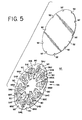
FIG. 5 is an exploded perspective view of a sensor pack used in the blood glucose sensor dispensing instrument ofFIG. 1 with the foil portion of the sensor pack separated from the base portion of the sensor pack and with a sensor disposed in each of the sensor cavities; -
FIG. 6 is top view of the base portion of the sensor pack ofFIG. 5 ; -
FIG. 7 is side view of the base portion of the sensor pack ofFIG. 5 ; -
FIG. 8 is bottom view of the base portion of the sensor pack ofFIG. 5 ; -
FIG. 9 is a top view of the sensor embodying the present invention; -
FIG. 10 is a side elevational view of the sensor ofFIG. 9 ; and -
FIG. 11 is a diagrammatic view illustrating the engagement of a knife blade with one of the sensors in the sensor pack ofFIG. 5 . - Referring now more specifically to the drawings, there is disclosed a blood glucose sensor dispensing instrument 30 (
FIGS. 1-4 ) that is adapted to have loaded therein a sensor pack 32 (FIGS. 5-8 ) in which is disposed a plurality of sensors or testing elements 34 (FIGS. 9-10 ) embodying the present invention. Thesensor dispensing instrument 30 includes anouter housing 36 having anupper case 38 and alower case 40. Theupper case 38 is pivotable with respect to thelower case 40 in a clam shell fashion so that thesensor pack 32 can be positioned within thehousing 36. With thesensor pack 32 loaded in thehousing 36, aslide actuator 42 on theupper case 38 of thehousing 36 manually is slid from a standby position (FIGS. 1-3 ) adjacent arear end 44 of theupper case 38 toward an actuated or testing position (FIG. 4 ) adjacent a forward or testingend 46 of theupper case 38. Theslide actuator 42 also can be moved to place thesensor dispensing instrument 30 in a data processing or display mode. - The movement of the
slide actuator 42 towards its testing position forces a knife blade assembly 48 (diagrammatically shown inFIG. 11 ) to move with respect to thesensor pack 32. Aknife blade 50 on theknife blade assembly 48 pierces a portion of afoil 52 covering one of a plurality ofsensor cavities 54A-J, such as thecavity 54J, in abase portion 56 of thesensor pack 32 that is in alignment with theknife blade 50. Thesensor 34 disposed in thecavity 54J is engaged by theknife blade 50 resulting in theknife blade 50 further severing thefoil 52 covering thesensor cavity 54J and forcing or ejecting thesensor 34 out from thesensor cavity 54J. - After the
sensor 34 has been completely ejected from thesensor cavity 54J, thesensor 34 becomes lodged in its testing position projecting out from thetesting end 46 of the sensor dispensing instrument 30 (FIG. 4 ).Contacts 58 on thesensor 34 are coupled within thehousing 36 to electronic circuitry (not shown) disposed in theupper case 38. The circuitry may include a microprocessor or the like for processing, storing and/or displaying data generated during a blood glucose test procedure. - Once the blood analyzing test is completed, the
sensor 34 is released from thehousing 36 and theslide actuator 42 is manually retracted in the opposite direction towards its standby position adjacent therear end 44 of theupper case 38. The retraction of theslide actuator 42 to its standby position results in the rotation of thesensor pack 32 so that the next one ofsensor cavities 54A-J is positioned in alignment with theknife blade 50 enabling thesensor 34 in the next sensor cavity 54I to be used in the next blood glucose testing procedure. - As is seen in
FIGS. 1-4 , theupper case 38 and thelower case 40 of thesensor dispensing housing 36 are complementary, generally round in shape containers that are adapted to be pivoted with respect to each other. Theupper case 38 and thelower case 40 are maintained in their closed configuration as shown inFIGS. 1-4 by alatch 60 that is pivotally mounted in a front ortesting section 62 of thelower case 40. When thelatch 60 is pivoted upwardly, it clips into arecess 64 in a front ortesting end section 66 of theupper case 38 thereby securing theupper case 38 and thelower case 40 in their closed configuration. - The
upper case 34 has arecess 68 that extends in its exteriorupper wall 70 from thefront section 66 to adjacent therear end 44. Theslide actuator 42 is adapted to be mounted within therecess 68 so that it can be slid forward toward thefront end 46 or retracted toward therear end 44. Aslide latch 72 is mounted on theslide actuator 42 and includes a plurality of raisednubs 74 that provides a surface facilitating the movement of theslide latch 72 and theslide actuator 42 by a person using thesensor dispensing instrument 30. - The movement of the
slide latch 72 determines in which of two operating modes the dispensinginstrument 30 is placed. In a first or testing mode, theslide latch 72 is positioned as shown inFIGS. 1, 2 and4 . In a second or data processing mode, theslide latch 72 is slid laterally with respect to theslide actuator 42. - When the
slide latch 72 is in its testing mode position, theknife blade assembly 48 is moved with respect to thefoil 52 and with respect to one of thesensors 34 within thesensor pack 32 as theslide actuator 42 is moved toward thetesting end 46. On the other hand, theknife blade assembly 48 is not moved as theslide actuator 42 is moved toward thetesting end 46 when theslide latch 72 is slid laterally with respect to theslide actuator 42 for placing the dispensinginstrument 30 into its data processing mode. Instead, data and other information concerning the status of the dispensinginstrument 30 and the test being performed is visible through alens 76 in therecess 68 near therear end 46 of theupper case 34 when theslide actuator 42 is moved toward thefront end 46 of the upper case 38 (see generallyFIG. 4 ). The displays appearing through thelens 76 when theinstrument 30 is in its data processing or display mode are controlled in part by actuatingbuttons rear end 44. For example, thebuttons - The
sensors 34 that are to be used in the dispensinginstrument 30 are packaged in thesensor pack 32 which is formed of the circularly shapedbase portion 56 and the correspondingly configuredfoil 52. The sensor cavities 54A-J are formed as depressions in thebase portion 56 with each of thesensor cavities 54A-J adapted to house one of thesensors 34. As illustrated with respect to thesensor cavity 54A inFIG. 6 , each of thesensor cavities 54A-J has abottom support wall 82 that extends from aninner end 84 to anouter end 86 of thesensor cavity 54A. Thesupport wall 82 is inclined or sloped slightly upward as it extends from theinner end 84 to theouter end 86. This sloping of thesupport wall 82 results in thesensor 34 being raised slightly as it is being ejected or excised from thesensor cavities 54A-J so that it will avoid or pass above that portion of the heat seal affixing thefoil 52 to thebase portion 56 along the outer peripheries of thefoil 52 and thebase portion 56. - Each of the
sensor cavities 54A-J is in fluid communication with a corresponding one ofdesiccant cavities 88A-J. Each of thedesiccant cavities 88A-J is formed of a small depression in thebase portion 56 adjacent the corresponding one of thesensor cavities 54A-J. Desiccant material is disposed in thedesiccant cavities 88A-J in order to insure that thesensor cavities 54A-J are maintained at an appropriate humidity level so that the reagent material in thesensor 34 disposed in theparticular sensor cavity 54A-J is not adversely affected prior to being used. The desiccant material might be in the form of a small bag or round bead of material or any other form that can be readily disposed in thedesiccant cavities 88A-J. The amount of such desiccant material placed in each of thedesiccant cavities 88A-J will be dependent on the amount that is required to maintain thesensor cavities 54A-J in a desiccate state. One type of desiccant material that could be used is sold under the trademark NATRASORB and is available in powder, pellet and bead forms. -
Notches 90 are formed along the outer peripheral edge of thebase portion 56. When thefoil 52 is sealed to thebase portion 56,notches 92 along the outer peripheral edge of thefoil 52 will be in alignment with thenotches 90 to thereby form an integral series of notches along the outer peripheral edge of thesensor pack 32. Each of the notches formed by thenotches sensor cavities 54A-J in thebase portion 56 such that when thesensor pack 32 is mounted within the dispensinginstrument 30, thesensor pack 32 can be rotated so that each one of thesensor cavities 54A-J will sequentially be placed into proper alignment with theknife blade 50 on theknife blade assembly 48 so that the individual ones of thesensors 34 within thesensor cavities 54A-J can be ejected from thosesensor cavities 54A-J. - The
foil 52 is adapted to cover the top of thebase portion 56 and be affixed to thebase portion 56 by heat sealing along the entire outer peripheral edge of thefoil 52 to the outer peripheral edge of thebase portion 56. Thefoil 52 also is heat sealed about the entire perimeter of each set of thesensor retaining cavities 54A-J and the desciccant cavities 88A-J to seal thesensor retaining cavities 54A-J and thedesiccant cavities 88A-J such that theindividual sensors 34 are maintained in a desiccated state and isolated from each other. As a result, the opening of one of thesensor cavities 54A-J will not affect the desiccated state of any of theother sensor cavities 54A-J. Thefoil 52 may be made of any material that will adequately seal thesensor cavities 54A-J and thedesiccant cavities 88A-J while providing a material that will can be really severed by theknife blade 50 and pierced by thesensor 34 as it is being pushed out from thesensor cavities 54A-J. One type of foil that can be used for thefoil 52 is AL-191-01 foil distributed by Alusuisse Flexible Packaging, Inc. - As is illustrated in
FIG. 8 , thebase portion 56 of thesensor pack 32 includes a label area 94 on its underside inwardly of thesensor cavities 54A-J. Aconductive label 96 is positioned in this label area 94 and provides calibration and production information that can be sensed when thesensor pack 32 is loaded into thesensor dispensing instrument 30. - The
sensor pack 32 is adapted to house tensensors 34 with one of the tensensors 34 in each of thesensor cavities 54A-J. As is illustrated inFIGS. 9-10 , each of thesensors 34 has a generally flat, rectangular shape, is formed of mated plastic pieces, i.e., alid 98 and abase 100, and extends from a front ortesting end 102 to a rear orejection end 104. Each of thesensors 34 is provided with a capillary channel that extends from the front, testingend 102 of thesensor 34 to biosensing or reagent material disposed between the matedpieces sensor 34. When thetesting end 102 of thesensor 34 is placed into fluid (for example, blood that is accumulated on a person's finger after the finger has been pricked), a portion of the fluid is drawn into the capillary channel by capillary action so that a sufficient amount of fluid to be tested is drawn into thesensor 34. The fluid then chemically reacts with the reagent material in thesensor 34 so that an electrical signal indicative of the blood glucose level in the blood being tested is supplied to thecontacts 58 and thereby to circuitry within thesensing instrument 30. - As will be discussed in more detail hereinafter, a front or
lead edge 106 of thelid 98 is offset longitudinally with respect to a front ortrail edge 108 of thebase 100 and thefront edges sensor 34 is being forced out of thesensor cavity 54J by theknife blade 50, thefront end 102 of thesensor 34 is adapted to puncture an unsevered portion of thefoil 52 overlying, for example, thesensor cavity 54J without ripping off a shard of thefoil 52. Therear end 104 of thesensor 34 includes asmall notch 110 into which theknife blade 50 will become disposed as theknife blade 50 is ejecting thesensor 34 from thesensor cavity 54J. Thenotch 110 provides a target area for theknife blade 50 to contact thesensor 34 and once theknife blade 50 is in contact with thenotch 110, thesensor 34 becomes centered on theknife blade 50. Thecontacts 58 on thelid 98 of thesensor 34 are adapted to be coupled to circuitry within thesensor dispensing instrument 30 when thesensor 34 is moved into its testing position illustrated inFIG. 4 . As a result, information generated in thesensor 34 during testing can be stored and/or analyzed. - As indicated above, the particular configuration of the front testing or
lead edge 106 of thelid 98 and the front testing ortrail edge 108 of thebase 100 and their positions relative to each other are of significance in ejecting thesensor 34 from thesensor cavities 54A-J without a shard being ripped from thefoil 52. More specifically, thesensor 34 is shown inFIG. 9 with alongitudinal axis 112 extending from therear end 104 to thefront end 102 and a transverse axis 114 extending perpendicularly with respect to thelongitudinal axis 112 from aside edge 116 to aside edge 118. Thefront testing edge 106 of thelid 98 overhangs thefront testing edge 108 of thebase 100 of thesensor 34 so that thefront testing edge 106 of thelid 98 is sufficiently forward in the direction along thelongitudinal axis 112 of thefront testing edge 108 of the base 100 that thefront testing edge 106 of thelid 98 forms essentially a separate and distinct cutting edge for severing thefoil 52 overlying thesensor cavity 54J. In one embodiment of thesensor 34, thefront edges front edges longitudinal axis 112 of thesensor 34. - A
front portion 120 of theside edge 116 of both thebase 100 and thelid 98 is beveled at about a 25° angle with respect to the longitudinal axis 112 (Angle A inFIG. 9 ). The front edges 106 and 108 of both thelid 98 and thebase 100, respectively, are biased with respect to the transverse axis 114 of thesensor 34. As viewed inFIG. 9 , thefront edge 108 of thebase 100 extends from the beveledfront portion 120 across the entire remaining width of thesensor 34 to theside edge 118 at an angle of approximately 10° with respect to the transverse axis 114 (Angle B inFIG. 9 ). Although thefront edge 106 of thelid 98 also is angled with respect to the transverse axis 114 of thesensor 34, it has two different and distinct angular portions. Amajor portion 122 of thefront lid edge 106 extends from thefront portion 120 across a significant portion of the width of thesensor 34 toward theside edge 118 at an angle of about 15° with respect to the transverse axis 114 of the sensor 34 (Angle C inFIG. 9 ). A remainingportion 124 of thefront edge 106 of thelid 98 extends from themajor portion 122 at a greater angle of about 25° with respect to the transverse axis 114 of the sensor 34 (Angle D inFIG. 9 ). As result, the remainingportion 124 forms a relativelypointed tip 126 at theside edge 118. - The
pointed tip 126 provides a knife like portion to thelid edge 106 so that thepointed tip 126 will initially pierce with a minimum force through thefoil 52 overlying thesensor cavity 54J in which thesensor 34 is disposed as thesensor 34 is being ejected from thesensor cavity 54J. As thesensor 34 continues to be ejected from thesensor cavity 54J, theangled edge portion 124 continues to sever thefoil 52. In some cases, a small piece or shard portion of thefoil 52 will begin to be formed even though thelid edge 106 is forward of thebase edge 108. However, this shard portion of thefoil 52 will not be completely torn from the remaining portion of thefoil 52. Instead, the shard portion will be folded back over the top of thefoil 52 as the lessangled portion 122 begins to engage thefoil 52 during the ejection or excision of thesensor 34. With the shard of foil folded over the top of thefoil 52, it will not be completely separated from the remaining portion of thefoil 52 and will remain in a location where it will not adversely affect the test being conducted with thesensor 34. - The overhang of the
lid 98 over thebase 100 of thesensor 34 and the particular biased angles for thefront edge 108 of thebase 100 and the biased angles of theportions front edge 106 of thelid 98 enables thesensor 34 to pierce through thefoil 52 overlying thesensor cavity 54J as thesensor 34 is being ejected without a shard of thefoil 52 being ripped away from thefoil 52. The biased angles and the spatial relationship between thefront edges sensor 34 being ejected from thecavity 54J with an acceptable minimum amount of force. - While the invention has been described with reference to details of the illustrated embodiment, these details are not intended to limit the scope of the invention as defined in the appended claims. For example, the
sensor 34 can be used with theinstrument 30 to test fluids other than blood glucose. In fact, thesensor 34 can be used to analyze any type chemistry fluid that can be analyzed by means of a reagent material.
Claims (8)
- A testing element (34) that is adapted to be ejected from within a cavity (54A-J) sealed by a foil (52) and that has a longitudinal axis (112) extending from a rear end (104) of said element (34) to a front end (102) of said element (34) and a transverse axis (114) extending perpendicularly to said longitudinal axis (112) between opposed side edges (116, 118) of said element (34), said element (34) comprising:a base (100) extending along said longitudinal axis (112) of said element (34) and having a front base edge (108); anda lid (98) mated with said base (100), extending along said longitudinal axis (112) of said element (34), and having a front lid edge (106),said front lid edge (106) and said front base edge (108) are biased with respect to said transverse axis (114);a reagent material disposed between the base (100) and the lid (98);a capillary channel that extends between the base (100) and the lid (98) from the front end (102) of said element (34) to said reagent material;characterized in thatsaid front lid edge (106) and said front base edge (108) are biased at angles which are different from each other and said front lid edge (106) extending adjacent to and forwardly of said front base edge (108) along said longitudinal axis (112) so that said front lid edge (106) overhangs said front base edge (108).
- A testing element (34) as set forth in claim 1
wherein said base (100) and said lid (98) are generally flat pieces mated together to form said element (34). - A testing element (34) as set forth in claim 1 or 2
wherein said front base edge (108) is biased at an angle of approximately 10 degrees with respect to said transverse axis (114). - A testing element (34) as set forth in one of the claims 1 to 3 wherein said front lid edge (106) has a first lid edge portion (122) biased at an angle of approximately 15 degrees with respect to said transverse axis (114) and a second lid edge portion (124) biased at an angle of approximately 25 degrees with respect to said transverse axis (114).
- A testing element (34) as set forth in claim 4
wherein said second lid edge portion (124) forms a pointed tip (126) at one side edge (116, 118) of said element (34), - A testing element (34) as set forth in one of the claims 1 to 5 wherein one of said side edges (116, 118) is beveled adjacent said front base edge (108) and said front lid edge (106).
- A testing element (34) as set forth in claim 6
wherein said one of said side edges (116, 118) is beveled at an angle of approximately 25 degrees with respect to said longitudinal axis. - A fluid testing sensor (34) as set forth in one of the claims 1 to 7 wherein said front lid edge (106) is at least 0,254 mm (10 thousandths of an inch) forward of said front base edge (108).
Applications Claiming Priority (2)
| Application Number | Priority Date | Filing Date | Title |
|---|---|---|---|
| US08/659,360 US5660791A (en) | 1996-06-06 | 1996-06-06 | Fluid testing sensor for use in dispensing instrument |
| US659360 | 1996-06-06 |
Publications (3)
| Publication Number | Publication Date |
|---|---|
| EP0811843A2 EP0811843A2 (en) | 1997-12-10 |
| EP0811843A3 EP0811843A3 (en) | 2004-06-23 |
| EP0811843B1 true EP0811843B1 (en) | 2011-10-05 |
Family
ID=24645086
Family Applications (1)
| Application Number | Title | Priority Date | Filing Date |
|---|---|---|---|
| EP97108865A Expired - Lifetime EP0811843B1 (en) | 1996-06-06 | 1997-06-03 | Fluid testing sensor for use in dispensing instruments |
Country Status (8)
| Country | Link |
|---|---|
| US (1) | US5660791A (en) |
| EP (1) | EP0811843B1 (en) |
| JP (1) | JP4047948B2 (en) |
| AT (1) | ATE527535T1 (en) |
| AU (1) | AU709487B2 (en) |
| CA (1) | CA2198946C (en) |
| DK (1) | DK0811843T3 (en) |
| ES (1) | ES2373214T3 (en) |
Cited By (2)
| Publication number | Priority date | Publication date | Assignee | Title |
|---|---|---|---|---|
| US8221332B2 (en) | 2003-11-12 | 2012-07-17 | Facet Technologies, Llc | Multi-lancet cartridge and lancing device |
| US8870903B2 (en) | 2002-02-21 | 2014-10-28 | Facet Technologies, Llc | Blood sampling device |
Families Citing this family (139)
| Publication number | Priority date | Publication date | Assignee | Title |
|---|---|---|---|---|
| CA2547299C (en) * | 1997-12-04 | 2009-03-03 | Roche Diagnostics Corporation | Instrument and method |
| US6391005B1 (en) | 1998-03-30 | 2002-05-21 | Agilent Technologies, Inc. | Apparatus and method for penetration with shaft having a sensor for sensing penetration depth |
| US7416699B2 (en) | 1998-08-14 | 2008-08-26 | The Board Of Trustees Of The Leland Stanford Junior University | Carbon nanotube devices |
| US20050037505A1 (en) * | 2000-05-11 | 2005-02-17 | James Samsoondar | Spectroscopic method and apparatus for analyte measurement |
| US7138089B2 (en) * | 2000-07-20 | 2006-11-21 | Hypoguard Limited | Test device for analyzing blood glucose or other analytes in bodily fluids |
| US6827899B2 (en) * | 2000-08-30 | 2004-12-07 | Hypoguard Limited | Test device |
| US8641644B2 (en) | 2000-11-21 | 2014-02-04 | Sanofi-Aventis Deutschland Gmbh | Blood testing apparatus having a rotatable cartridge with multiple lancing elements and testing means |
| US6752817B2 (en) * | 2001-03-26 | 2004-06-22 | Bayer Corporation | Split pressure ring for lancing device and method of operation |
| DE60229988D1 (en) | 2001-06-08 | 2009-01-02 | Roche Diagnostics Gmbh | Removal device for Körperflussigkeiten |
| US9427532B2 (en) | 2001-06-12 | 2016-08-30 | Sanofi-Aventis Deutschland Gmbh | Tissue penetration device |
| US9226699B2 (en) | 2002-04-19 | 2016-01-05 | Sanofi-Aventis Deutschland Gmbh | Body fluid sampling module with a continuous compression tissue interface surface |
| DE60234598D1 (en) | 2001-06-12 | 2010-01-14 | Pelikan Technologies Inc | SELF-OPTIMIZING LANZET DEVICE WITH ADAPTANT FOR TEMPORAL FLUCTUATIONS OF SKIN PROPERTIES |
| US9795747B2 (en) | 2010-06-02 | 2017-10-24 | Sanofi-Aventis Deutschland Gmbh | Methods and apparatus for lancet actuation |
| US7981056B2 (en) | 2002-04-19 | 2011-07-19 | Pelikan Technologies, Inc. | Methods and apparatus for lancet actuation |
| US8337419B2 (en) | 2002-04-19 | 2012-12-25 | Sanofi-Aventis Deutschland Gmbh | Tissue penetration device |
| US7025774B2 (en) | 2001-06-12 | 2006-04-11 | Pelikan Technologies, Inc. | Tissue penetration device |
| US7749174B2 (en) | 2001-06-12 | 2010-07-06 | Pelikan Technologies, Inc. | Method and apparatus for lancet launching device intergrated onto a blood-sampling cartridge |
| ATE485766T1 (en) | 2001-06-12 | 2010-11-15 | Pelikan Technologies Inc | ELECTRICAL ACTUATING ELEMENT FOR A LANCET |
| US7611899B2 (en) * | 2001-08-13 | 2009-11-03 | Bayer Healthcare Llc | Sensor release for a sensor dispensing instrument |
| US7323141B2 (en) * | 2001-08-13 | 2008-01-29 | Bayer Healthcare Llc | Button layout for a testing instrument |
| US7723113B2 (en) * | 2001-08-20 | 2010-05-25 | Bayer Healthcare Llc | Packaging system for test sensors |
| US6997343B2 (en) * | 2001-11-14 | 2006-02-14 | Hypoguard Limited | Sensor dispensing device |
| US20030111357A1 (en) * | 2001-12-13 | 2003-06-19 | Black Murdo M. | Test meter calibration |
| US7004928B2 (en) | 2002-02-08 | 2006-02-28 | Rosedale Medical, Inc. | Autonomous, ambulatory analyte monitor or drug delivery device |
| DE10245721A1 (en) * | 2002-02-21 | 2003-12-11 | Hartmann Paul Ag | Blood analyzer device comprises needles, test media, analyzer and display, and has carrier turned with respect to main body, to position needle and test media |
| US20030169426A1 (en) * | 2002-03-08 | 2003-09-11 | Peterson Timothy A. | Test member orientation |
| CA2419905C (en) | 2002-03-18 | 2016-01-05 | Bayer Healthcare, Llc | Storage cartridge for biosensors |
| US6881578B2 (en) * | 2002-04-02 | 2005-04-19 | Lifescan, Inc. | Analyte concentration determination meters and methods of using the same |
| US7901362B2 (en) | 2002-04-19 | 2011-03-08 | Pelikan Technologies, Inc. | Method and apparatus for penetrating tissue |
| US9314194B2 (en) | 2002-04-19 | 2016-04-19 | Sanofi-Aventis Deutschland Gmbh | Tissue penetration device |
| US8221334B2 (en) | 2002-04-19 | 2012-07-17 | Sanofi-Aventis Deutschland Gmbh | Method and apparatus for penetrating tissue |
| US7175642B2 (en) | 2002-04-19 | 2007-02-13 | Pelikan Technologies, Inc. | Methods and apparatus for lancet actuation |
| US7976476B2 (en) | 2002-04-19 | 2011-07-12 | Pelikan Technologies, Inc. | Device and method for variable speed lancet |
| US7547287B2 (en) | 2002-04-19 | 2009-06-16 | Pelikan Technologies, Inc. | Method and apparatus for penetrating tissue |
| US7674232B2 (en) | 2002-04-19 | 2010-03-09 | Pelikan Technologies, Inc. | Method and apparatus for penetrating tissue |
| US7331931B2 (en) | 2002-04-19 | 2008-02-19 | Pelikan Technologies, Inc. | Method and apparatus for penetrating tissue |
| US7909778B2 (en) | 2002-04-19 | 2011-03-22 | Pelikan Technologies, Inc. | Method and apparatus for penetrating tissue |
| US7892185B2 (en) | 2002-04-19 | 2011-02-22 | Pelikan Technologies, Inc. | Method and apparatus for body fluid sampling and analyte sensing |
| US8360992B2 (en) | 2002-04-19 | 2013-01-29 | Sanofi-Aventis Deutschland Gmbh | Method and apparatus for penetrating tissue |
| US9795334B2 (en) | 2002-04-19 | 2017-10-24 | Sanofi-Aventis Deutschland Gmbh | Method and apparatus for penetrating tissue |
| US7229458B2 (en) | 2002-04-19 | 2007-06-12 | Pelikan Technologies, Inc. | Method and apparatus for penetrating tissue |
| US7491178B2 (en) | 2002-04-19 | 2009-02-17 | Pelikan Technologies, Inc. | Method and apparatus for penetrating tissue |
| US8702624B2 (en) | 2006-09-29 | 2014-04-22 | Sanofi-Aventis Deutschland Gmbh | Analyte measurement device with a single shot actuator |
| US9248267B2 (en) | 2002-04-19 | 2016-02-02 | Sanofi-Aventis Deustchland Gmbh | Tissue penetration device |
| US7892183B2 (en) | 2002-04-19 | 2011-02-22 | Pelikan Technologies, Inc. | Method and apparatus for body fluid sampling and analyte sensing |
| US7232451B2 (en) | 2002-04-19 | 2007-06-19 | Pelikan Technologies, Inc. | Method and apparatus for penetrating tissue |
| US8267870B2 (en) | 2002-04-19 | 2012-09-18 | Sanofi-Aventis Deutschland Gmbh | Method and apparatus for body fluid sampling with hybrid actuation |
| US8784335B2 (en) | 2002-04-19 | 2014-07-22 | Sanofi-Aventis Deutschland Gmbh | Body fluid sampling device with a capacitive sensor |
| US8579831B2 (en) | 2002-04-19 | 2013-11-12 | Sanofi-Aventis Deutschland Gmbh | Method and apparatus for penetrating tissue |
| US7297122B2 (en) | 2002-04-19 | 2007-11-20 | Pelikan Technologies, Inc. | Method and apparatus for penetrating tissue |
| US7226461B2 (en) | 2002-04-19 | 2007-06-05 | Pelikan Technologies, Inc. | Method and apparatus for a multi-use body fluid sampling device with sterility barrier release |
| US7343188B2 (en) * | 2002-05-09 | 2008-03-11 | Lifescan, Inc. | Devices and methods for accessing and analyzing physiological fluid |
| US20030211619A1 (en) * | 2002-05-09 | 2003-11-13 | Lorin Olson | Continuous strip of fluid sampling and testing devices and methods of making, packaging and using the same |
| CN100498320C (en) * | 2002-05-23 | 2009-06-10 | 爱科来株式会社 | Analyzer, analyzer device, analyzing tool assembly and its manufacture method |
| US7250095B2 (en) * | 2002-07-11 | 2007-07-31 | Hypoguard Limited | Enzyme electrodes and method of manufacture |
| AU2003234944A1 (en) * | 2002-08-27 | 2004-03-18 | Bayer Healthcare, Llc | Methods of Determining Glucose Concentration in Whole Blood Samples |
| IES20020794A2 (en) * | 2002-10-04 | 2003-02-19 | Minroc Techn Promotions Ltd | A down-the-hole hammer |
| US7572237B2 (en) | 2002-11-06 | 2009-08-11 | Abbott Diabetes Care Inc. | Automatic biological analyte testing meter with integrated lancing device and methods of use |
| US8574895B2 (en) | 2002-12-30 | 2013-11-05 | Sanofi-Aventis Deutschland Gmbh | Method and apparatus using optical techniques to measure analyte levels |
| US7264139B2 (en) * | 2003-01-14 | 2007-09-04 | Hypoguard Limited | Sensor dispensing device |
| US7132041B2 (en) * | 2003-02-11 | 2006-11-07 | Bayer Healthcare Llc | Methods of determining the concentration of an analyte in a fluid test sample |
| US7052652B2 (en) | 2003-03-24 | 2006-05-30 | Rosedale Medical, Inc. | Analyte concentration detection devices and methods |
| EP1628567B1 (en) | 2003-05-30 | 2010-08-04 | Pelikan Technologies Inc. | Method and apparatus for fluid injection |
| DK1633235T3 (en) | 2003-06-06 | 2014-08-18 | Sanofi Aventis Deutschland | Apparatus for sampling body fluid and detecting analyte |
| WO2006001797A1 (en) | 2004-06-14 | 2006-01-05 | Pelikan Technologies, Inc. | Low pain penetrating |
| US7364699B2 (en) * | 2003-06-18 | 2008-04-29 | Bayer Healthcare Llc | Containers for reading and handling diagnostic reagents and methods of using the same |
| US20040267299A1 (en) * | 2003-06-30 | 2004-12-30 | Kuriger Rex J. | Lancing devices and methods of using the same |
| WO2005018454A2 (en) | 2003-08-20 | 2005-03-03 | Facet Technologies, Llc | Multi-lancet device with sterility cap repositioning mechanism |
| US7655019B2 (en) | 2003-08-20 | 2010-02-02 | Facet Technologies, Llc | Blood sampling device |
| US8282576B2 (en) | 2003-09-29 | 2012-10-09 | Sanofi-Aventis Deutschland Gmbh | Method and apparatus for an improved sample capture device |
| EP1680014A4 (en) | 2003-10-14 | 2009-01-21 | Pelikan Technologies Inc | Method and apparatus for a variable user interface |
| US8007656B2 (en) | 2003-10-24 | 2011-08-30 | Bayer Healthcare Llc | Enzymatic electrochemical biosensor |
| US7822454B1 (en) | 2005-01-03 | 2010-10-26 | Pelikan Technologies, Inc. | Fluid sampling device with improved analyte detecting member configuration |
| EP1706026B1 (en) | 2003-12-31 | 2017-03-01 | Sanofi-Aventis Deutschland GmbH | Method and apparatus for improving fluidic flow and sample capture |
| US20050150762A1 (en) * | 2004-01-09 | 2005-07-14 | Butters Colin W. | Biosensor and method of manufacture |
| EP1713926B1 (en) | 2004-02-06 | 2012-08-01 | Bayer HealthCare, LLC | Oxidizable species as an internal reference for biosensors and method of use |
| EP2752662B1 (en) * | 2004-02-06 | 2020-01-29 | Ascensia Diabetes Care Holdings AG | Fluid testing sensor having vents for directing fluid flow |
| US7807043B2 (en) * | 2004-02-23 | 2010-10-05 | Oakville Hong Kong Company Limited | Microfluidic test device |
| US8828203B2 (en) | 2004-05-20 | 2014-09-09 | Sanofi-Aventis Deutschland Gmbh | Printable hydrogels for biosensors |
| EP1765194A4 (en) | 2004-06-03 | 2010-09-29 | Pelikan Technologies Inc | Method and apparatus for a fluid sampling device |
| US9775553B2 (en) | 2004-06-03 | 2017-10-03 | Sanofi-Aventis Deutschland Gmbh | Method and apparatus for a fluid sampling device |
| ES2567060T3 (en) * | 2004-06-17 | 2016-04-19 | Bayer Healthcare Llc | Detection of incomplete filling of biosensors |
| US7582262B2 (en) * | 2004-06-18 | 2009-09-01 | Roche Diagnostics Operations, Inc. | Dispenser for flattened articles |
| CN101044400A (en) * | 2004-09-20 | 2007-09-26 | 拜尔保健有限公司 | Plastic knife for sensor-dispensing instrument |
| CA2584766A1 (en) * | 2004-10-20 | 2006-04-27 | Jeffery S. Reynolds | Cartridge for containing and dispensing test sensors |
| RU2401429C2 (en) * | 2004-12-13 | 2010-10-10 | Байер Хелткэр Ллк | Method for revealing differences between blood and reference solution, containing same analysed substance |
| US8652831B2 (en) | 2004-12-30 | 2014-02-18 | Sanofi-Aventis Deutschland Gmbh | Method and apparatus for analyte measurement test time |
| CA2600132C (en) * | 2005-03-04 | 2014-09-09 | Bayer Healthcare Llc | Stabilizing enzyme activity in electrochemical biosensors |
| WO2006102348A1 (en) | 2005-03-22 | 2006-09-28 | Bayer Healthcare Llc | Packaging container for test sensors |
| EP1877778A1 (en) * | 2005-03-22 | 2008-01-16 | Bayer HealthCare LLC | Packaging container for test sensors |
| CN101180403B (en) | 2005-04-08 | 2014-11-12 | 拜尔保健有限公司 | Oxidizable species as an internal reference in control solutions for biosensors |
| US20060281187A1 (en) | 2005-06-13 | 2006-12-14 | Rosedale Medical, Inc. | Analyte detection devices and methods with hematocrit/volume correction and feedback control |
| KR101321296B1 (en) | 2005-07-20 | 2013-10-28 | 바이엘 헬스케어 엘엘씨 | Gated amperometry temperature determination |
| EP1928304B1 (en) | 2005-09-30 | 2012-10-24 | Intuity Medical, Inc. | Catalysts for body fluid sample extraction |
| US8801631B2 (en) | 2005-09-30 | 2014-08-12 | Intuity Medical, Inc. | Devices and methods for facilitating fluid transport |
| JP5671205B2 (en) | 2005-09-30 | 2015-02-18 | バイエル・ヘルスケア・エルエルシー | Gated voltammetry |
| WO2007087582A1 (en) | 2006-01-24 | 2007-08-02 | Invitrogen Corporation | Device and methods for quantifying analytes |
| US8388906B2 (en) * | 2006-03-13 | 2013-03-05 | Nipro Diagnostics, Inc. | Apparatus for dispensing test strips |
| US11559810B2 (en) | 2006-03-13 | 2023-01-24 | Trividia Health, Inc. | Method and apparatus for coding diagnostic meters |
| US8940246B2 (en) | 2006-03-13 | 2015-01-27 | Nipro Diagnostics, Inc. | Method and apparatus for coding diagnostic meters |
| US8388905B2 (en) * | 2006-03-13 | 2013-03-05 | Nipro Diagnostics, Inc. | Method and apparatus for coding diagnostic meters |
| US8529751B2 (en) | 2006-03-31 | 2013-09-10 | Lifescan, Inc. | Systems and methods for discriminating control solution from a physiological sample |
| EP2008088B1 (en) | 2006-04-10 | 2011-06-29 | Bayer HealthCare LLC | Correction of oxygen effect in test sensor using reagents |
| US7993512B2 (en) | 2006-07-11 | 2011-08-09 | Bayer Healthcare, Llc | Electrochemical test sensor |
| WO2008016564A2 (en) * | 2006-07-31 | 2008-02-07 | Bayer Healthcare Llc | Packaging system for testing devices |
| US7797987B2 (en) * | 2006-10-11 | 2010-09-21 | Bayer Healthcare Llc | Test sensor with a side vent and method of making the same |
| ES2825036T3 (en) | 2006-10-24 | 2021-05-14 | Ascensia Diabetes Care Holdings Ag | Transient decay amperometry |
| US20080133059A1 (en) * | 2006-12-05 | 2008-06-05 | Bayer Healthcare Llc | Table-driven test sequence |
| WO2008085251A1 (en) * | 2007-01-05 | 2008-07-17 | Bayer Healthcare Llc | Electrochemical test sensor with light guide |
| US20100099192A1 (en) * | 2007-03-12 | 2010-04-22 | Bayer Healthcare, Llc | Test-sensor cartridge |
| WO2008111937A1 (en) | 2007-03-12 | 2008-09-18 | Bayer Healthcare Llc | Analyte-testing instruments |
| EP1970006A1 (en) * | 2007-03-14 | 2008-09-17 | Roche Diagnostics GmbH | Analysis system for determining a analyte in a body fluid and disposable integrated sample extraction and analysis element |
| US8083677B2 (en) * | 2007-09-24 | 2011-12-27 | Baxter International Inc. | Access disconnect detection using glucose |
| US8778168B2 (en) * | 2007-09-28 | 2014-07-15 | Lifescan, Inc. | Systems and methods of discriminating control solution from a physiological sample |
| AU2011224097B2 (en) * | 2007-09-28 | 2012-09-20 | Lifescan, Inc. | Systems and methods for discriminating control solution from a physiological sample |
| WO2009076302A1 (en) | 2007-12-10 | 2009-06-18 | Bayer Healthcare Llc | Control markers for auto-detection of control solution and methods of use |
| US8603768B2 (en) | 2008-01-17 | 2013-12-10 | Lifescan, Inc. | System and method for measuring an analyte in a sample |
| WO2009126900A1 (en) | 2008-04-11 | 2009-10-15 | Pelikan Technologies, Inc. | Method and apparatus for analyte detecting device |
| WO2009145920A1 (en) | 2008-05-30 | 2009-12-03 | Intuity Medical, Inc. | Body fluid sampling device -- sampling site interface |
| US8394637B2 (en) * | 2008-06-02 | 2013-03-12 | Roche Diagnostics Operations, Inc. | Handheld analyzer for testing a sample |
| US20090305317A1 (en) * | 2008-06-05 | 2009-12-10 | Brauer Jacob S | User interface for testing device |
| US9636051B2 (en) | 2008-06-06 | 2017-05-02 | Intuity Medical, Inc. | Detection meter and mode of operation |
| EP2299904B1 (en) | 2008-06-06 | 2019-09-11 | Intuity Medical, Inc. | Medical measurement method |
| US8551320B2 (en) | 2008-06-09 | 2013-10-08 | Lifescan, Inc. | System and method for measuring an analyte in a sample |
| US9375169B2 (en) | 2009-01-30 | 2016-06-28 | Sanofi-Aventis Deutschland Gmbh | Cam drive for managing disposable penetrating member actions with a single motor and motor and control system |
| US9517027B2 (en) | 2009-07-10 | 2016-12-13 | Facet Techonologies, Llc | Advancement mechanism for cartridge-based devices |
| EP3106871B1 (en) | 2009-11-30 | 2021-10-27 | Intuity Medical, Inc. | A method of verifying the accuracy of the operation of an analyte monitoring device |
| US8550295B2 (en) * | 2010-02-22 | 2013-10-08 | Roche Diagnostics Operations, Inc. | Container for dispensing a single test strip |
| US8965476B2 (en) | 2010-04-16 | 2015-02-24 | Sanofi-Aventis Deutschland Gmbh | Tissue penetration device |
| CA2803797A1 (en) | 2010-06-25 | 2011-12-29 | Intuity Medical, Inc. | Analyte monitoring methods and systems |
| EP3407064B1 (en) | 2011-08-03 | 2020-04-22 | Intuity Medical, Inc. | Body fluid sampling arrangement |
| WO2013096268A1 (en) | 2011-12-20 | 2013-06-27 | Bayer Heal Thcare Llc | Linear, cartridge-based glucose measurement system |
| US9097700B2 (en) | 2011-12-29 | 2015-08-04 | Bayer Healthcare Llc | Glucose measurement system with high-capacity cartridge and capability of more frequent replenishment |
| CN107085092B (en) | 2012-05-31 | 2020-07-17 | 安晟信医疗科技控股公司 | Replaceable multi-strip cartridge and biosensor meter |
| EP2856155B1 (en) | 2012-05-31 | 2017-05-24 | Ascensia Diabetes Care Holdings AG | Multistrip cartridge |
| CN105209908B (en) | 2013-03-12 | 2018-01-09 | 安晟信医疗科技控股公司 | With the test-strips gauge for push to test bar against the mechanism of optical reader |
| US9376708B2 (en) | 2013-03-13 | 2016-06-28 | Ascensia Diabetes Care Holdings Ag | Bottled glucose sensor with no handling |
| US10729386B2 (en) | 2013-06-21 | 2020-08-04 | Intuity Medical, Inc. | Analyte monitoring system with audible feedback |
| US10712335B2 (en) | 2014-06-19 | 2020-07-14 | Ascensia Diabetes Care Holdings Ag | Sensor clip for stacked sensor dispensing system, and systems, methods and devices for making and using the same |
Family Cites Families (10)
| Publication number | Priority date | Publication date | Assignee | Title |
|---|---|---|---|---|
| US3932133A (en) * | 1973-07-31 | 1976-01-13 | Olympus Optical Co., Ltd. | System for detecting the particular chemical component of a test fluid |
| US4273639A (en) * | 1979-06-20 | 1981-06-16 | Eastman Kodak Company | Capillary bridge in apparatus for determining ionic activity |
| JPS6142107Y2 (en) * | 1979-11-30 | 1986-11-29 | ||
| JPS61198041A (en) * | 1985-02-28 | 1986-09-02 | Konishiroku Photo Ind Co Ltd | Biochemical-analyzing instrument |
| US4948737A (en) * | 1989-01-05 | 1990-08-14 | Eastman Kodak Company | Cartridge for properly receiving test elements |
| US5500375A (en) * | 1993-04-13 | 1996-03-19 | Serex, Inc. | Integrated packaging-holder device for immunochromatographic assays in flow-through or dipstick formats |
| DK0622119T3 (en) * | 1993-04-23 | 2000-04-10 | Roche Diagnostics Gmbh | Test element storage system |
| DE4326931A1 (en) * | 1993-08-11 | 1995-02-16 | Hoechst Ag | Device for removing solid dosage forms from blister packs |
| US5630986A (en) * | 1995-01-13 | 1997-05-20 | Bayer Corporation | Dispensing instrument for fluid monitoring sensors |
| US5510266A (en) * | 1995-05-05 | 1996-04-23 | Bayer Corporation | Method and apparatus of handling multiple sensors in a glucose monitoring instrument system |
-
1996
- 1996-06-06 US US08/659,360 patent/US5660791A/en not_active Expired - Lifetime
-
1997
- 1997-03-03 CA CA002198946A patent/CA2198946C/en not_active Expired - Lifetime
- 1997-06-03 AT AT97108865T patent/ATE527535T1/en not_active IP Right Cessation
- 1997-06-03 EP EP97108865A patent/EP0811843B1/en not_active Expired - Lifetime
- 1997-06-03 DK DK97108865.3T patent/DK0811843T3/en active
- 1997-06-03 ES ES97108865T patent/ES2373214T3/en not_active Expired - Lifetime
- 1997-06-05 AU AU24717/97A patent/AU709487B2/en not_active Expired
- 1997-06-05 JP JP14737597A patent/JP4047948B2/en not_active Expired - Fee Related
Cited By (2)
| Publication number | Priority date | Publication date | Assignee | Title |
|---|---|---|---|---|
| US8870903B2 (en) | 2002-02-21 | 2014-10-28 | Facet Technologies, Llc | Blood sampling device |
| US8221332B2 (en) | 2003-11-12 | 2012-07-17 | Facet Technologies, Llc | Multi-lancet cartridge and lancing device |
Also Published As
| Publication number | Publication date |
|---|---|
| CA2198946A1 (en) | 1997-12-06 |
| EP0811843A2 (en) | 1997-12-10 |
| DK0811843T3 (en) | 2012-07-16 |
| AU2471797A (en) | 1997-12-11 |
| ATE527535T1 (en) | 2011-10-15 |
| US5660791A (en) | 1997-08-26 |
| EP0811843A3 (en) | 2004-06-23 |
| AU709487B2 (en) | 1999-08-26 |
| CA2198946C (en) | 2003-05-20 |
| JPH1062424A (en) | 1998-03-06 |
| JP4047948B2 (en) | 2008-02-13 |
| ES2373214T3 (en) | 2012-02-01 |
Similar Documents
| Publication | Publication Date | Title |
|---|---|---|
| EP0811843B1 (en) | Fluid testing sensor for use in dispensing instruments | |
| JP3499364B2 (en) | Device for handling multiple sensors in a glucose monitor system | |
| US5632410A (en) | Means of handling multiple sensors in a glucose monitoring instrument system | |
| EP0732590B1 (en) | Dispensing instrument for fluid monitoring sensors | |
| US5738244A (en) | Dispensing instrument for fluid monitoring sensors | |
| US5810199A (en) | Dispensing instrument for fluid monitoring sensor | |
| US7279130B2 (en) | Sensor dispensing instrument having an activation mechanism and methods of using the same | |
| EP1284161B1 (en) | Blood glucose sensor dispensing instrument | |
| US7906336B2 (en) | Sensor dispensing instrument | |
| JP4049634B2 (en) | Blood glucose sensor dispensing device with modular electronics assembly | |
| JP2003139777A (en) | Packaging system for test sensor | |
| US20070257050A1 (en) | Blood Glucose Sensor Dispensing Instrument Having a Serrated Knife | |
| CA2531255C (en) | Dispensing instrument for fluid monitoring sensors |
Legal Events
| Date | Code | Title | Description |
|---|---|---|---|
| PUAI | Public reference made under article 153(3) epc to a published international application that has entered the european phase |
Free format text: ORIGINAL CODE: 0009012 |
|
| AK | Designated contracting states |
Kind code of ref document: A2 Designated state(s): AT BE CH DE DK ES FI FR GB GR IE IT LI LU MC NL PT SE |
|
| PUAL | Search report despatched |
Free format text: ORIGINAL CODE: 0009013 |
|
| AK | Designated contracting states |
Kind code of ref document: A3 Designated state(s): AT BE CH DE DK ES FI FR GB GR IE IT LI LU MC NL PT SE |
|
| RIC1 | Information provided on ipc code assigned before grant |
Ipc: 7B 01L 11/00 B Ipc: 7G 01N 33/487 A |
|
| 17P | Request for examination filed |
Effective date: 20041223 |
|
| AKX | Designation fees paid |
Designated state(s): AT BE CH DE DK ES FI FR GB GR IE IT LI LU NL PT SE |
|
| GRAP | Despatch of communication of intention to grant a patent |
Free format text: ORIGINAL CODE: EPIDOSNIGR1 |
|
| RIC1 | Information provided on ipc code assigned before grant |
Ipc: G01N 27/327 20060101AFI20110120BHEP |
|
| GRAS | Grant fee paid |
Free format text: ORIGINAL CODE: EPIDOSNIGR3 |
|
| GRAA | (expected) grant |
Free format text: ORIGINAL CODE: 0009210 |
|
| AK | Designated contracting states |
Kind code of ref document: B1 Designated state(s): AT BE CH DE DK ES FI FR GB GR IE IT LI LU NL PT SE |
|
| REG | Reference to a national code |
Ref country code: GB Ref legal event code: FG4D |
|
| REG | Reference to a national code |
Ref country code: CH Ref legal event code: EP |
|
| REG | Reference to a national code |
Ref country code: IE Ref legal event code: FG4D |
|
| REG | Reference to a national code |
Ref country code: DE Ref legal event code: R096 Ref document number: 69740301 Country of ref document: DE Effective date: 20111201 |
|
| REG | Reference to a national code |
Ref country code: SE Ref legal event code: TRGR |
|
| REG | Reference to a national code |
Ref country code: NL Ref legal event code: VDEP Effective date: 20111005 |
|
| REG | Reference to a national code |
Ref country code: ES Ref legal event code: FG2A Ref document number: 2373214 Country of ref document: ES Kind code of ref document: T3 Effective date: 20120201 |
|
| REG | Reference to a national code |
Ref country code: AT Ref legal event code: MK05 Ref document number: 527535 Country of ref document: AT Kind code of ref document: T Effective date: 20111005 |
|
| PG25 | Lapsed in a contracting state [announced via postgrant information from national office to epo] |
Ref country code: BE Free format text: LAPSE BECAUSE OF FAILURE TO SUBMIT A TRANSLATION OF THE DESCRIPTION OR TO PAY THE FEE WITHIN THE PRESCRIBED TIME-LIMIT Effective date: 20111005 |
|
| PG25 | Lapsed in a contracting state [announced via postgrant information from national office to epo] |
Ref country code: NL Free format text: LAPSE BECAUSE OF FAILURE TO SUBMIT A TRANSLATION OF THE DESCRIPTION OR TO PAY THE FEE WITHIN THE PRESCRIBED TIME-LIMIT Effective date: 20111005 Ref country code: GR Free format text: LAPSE BECAUSE OF FAILURE TO SUBMIT A TRANSLATION OF THE DESCRIPTION OR TO PAY THE FEE WITHIN THE PRESCRIBED TIME-LIMIT Effective date: 20120106 Ref country code: PT Free format text: LAPSE BECAUSE OF FAILURE TO SUBMIT A TRANSLATION OF THE DESCRIPTION OR TO PAY THE FEE WITHIN THE PRESCRIBED TIME-LIMIT Effective date: 20120206 |
|
| REG | Reference to a national code |
Ref country code: DK Ref legal event code: T3 |
|
| PLBE | No opposition filed within time limit |
Free format text: ORIGINAL CODE: 0009261 |
|
| STAA | Information on the status of an ep patent application or granted ep patent |
Free format text: STATUS: NO OPPOSITION FILED WITHIN TIME LIMIT |
|
| 26N | No opposition filed |
Effective date: 20120706 |
|
| REG | Reference to a national code |
Ref country code: DE Ref legal event code: R097 Ref document number: 69740301 Country of ref document: DE Effective date: 20120706 |
|
| PG25 | Lapsed in a contracting state [announced via postgrant information from national office to epo] |
Ref country code: AT Free format text: LAPSE BECAUSE OF FAILURE TO SUBMIT A TRANSLATION OF THE DESCRIPTION OR TO PAY THE FEE WITHIN THE PRESCRIBED TIME-LIMIT Effective date: 20111005 |
|
| REG | Reference to a national code |
Ref country code: IE Ref legal event code: MM4A |
|
| PG25 | Lapsed in a contracting state [announced via postgrant information from national office to epo] |
Ref country code: IE Free format text: LAPSE BECAUSE OF NON-PAYMENT OF DUE FEES Effective date: 20120603 |
|
| PG25 | Lapsed in a contracting state [announced via postgrant information from national office to epo] |
Ref country code: LU Free format text: LAPSE BECAUSE OF NON-PAYMENT OF DUE FEES Effective date: 20120603 |
|
| REG | Reference to a national code |
Ref country code: FR Ref legal event code: PLFP Year of fee payment: 19 |
|
| PGFP | Annual fee paid to national office [announced via postgrant information from national office to epo] |
Ref country code: DE Payment date: 20150629 Year of fee payment: 19 |
|
| REG | Reference to a national code |
Ref country code: FR Ref legal event code: PLFP Year of fee payment: 20 |
|
| PGFP | Annual fee paid to national office [announced via postgrant information from national office to epo] |
Ref country code: CH Payment date: 20160627 Year of fee payment: 20 Ref country code: ES Payment date: 20160627 Year of fee payment: 20 Ref country code: GB Payment date: 20160627 Year of fee payment: 20 Ref country code: FI Payment date: 20160629 Year of fee payment: 20 |
|
| PGFP | Annual fee paid to national office [announced via postgrant information from national office to epo] |
Ref country code: SE Payment date: 20160629 Year of fee payment: 20 Ref country code: DK Payment date: 20160627 Year of fee payment: 20 Ref country code: FR Payment date: 20160628 Year of fee payment: 20 |
|
| PGFP | Annual fee paid to national office [announced via postgrant information from national office to epo] |
Ref country code: IT Payment date: 20160627 Year of fee payment: 20 |
|
| REG | Reference to a national code |
Ref country code: DE Ref legal event code: R119 Ref document number: 69740301 Country of ref document: DE |
|
| PG25 | Lapsed in a contracting state [announced via postgrant information from national office to epo] |
Ref country code: DE Free format text: LAPSE BECAUSE OF NON-PAYMENT OF DUE FEES Effective date: 20170103 |
|
| REG | Reference to a national code |
Ref country code: DK Ref legal event code: EUP Effective date: 20170603 |
|
| REG | Reference to a national code |
Ref country code: CH Ref legal event code: PL |
|
| REG | Reference to a national code |
Ref country code: GB Ref legal event code: PE20 Expiry date: 20170602 |
|
| PG25 | Lapsed in a contracting state [announced via postgrant information from national office to epo] |
Ref country code: GB Free format text: LAPSE BECAUSE OF EXPIRATION OF PROTECTION Effective date: 20170602 |
|
| REG | Reference to a national code |
Ref country code: SE Ref legal event code: EUG |
|
| REG | Reference to a national code |
Ref country code: ES Ref legal event code: FD2A Effective date: 20180508 |
|
| PG25 | Lapsed in a contracting state [announced via postgrant information from national office to epo] |
Ref country code: ES Free format text: LAPSE BECAUSE OF EXPIRATION OF PROTECTION Effective date: 20170604 |