EP0813781B1 - Broadband switching system - Google Patents
Broadband switching system Download PDFInfo
- Publication number
- EP0813781B1 EP0813781B1 EP96904976A EP96904976A EP0813781B1 EP 0813781 B1 EP0813781 B1 EP 0813781B1 EP 96904976 A EP96904976 A EP 96904976A EP 96904976 A EP96904976 A EP 96904976A EP 0813781 B1 EP0813781 B1 EP 0813781B1
- Authority
- EP
- European Patent Office
- Prior art keywords
- bandwidth
- cells
- ingress
- signal
- control means
- Prior art date
- Legal status (The legal status is an assumption and is not a legal conclusion. Google has not performed a legal analysis and makes no representation as to the accuracy of the status listed.)
- Expired - Lifetime
Links
Images


Classifications
-
- H—ELECTRICITY
- H04—ELECTRIC COMMUNICATION TECHNIQUE
- H04Q—SELECTING
- H04Q11/00—Selecting arrangements for multiplex systems
- H04Q11/04—Selecting arrangements for multiplex systems for time-division multiplexing
-
- H—ELECTRICITY
- H04—ELECTRIC COMMUNICATION TECHNIQUE
- H04L—TRANSMISSION OF DIGITAL INFORMATION, e.g. TELEGRAPHIC COMMUNICATION
- H04L12/00—Data switching networks
- H04L12/54—Store-and-forward switching systems
- H04L12/56—Packet switching systems
- H04L12/5601—Transfer mode dependent, e.g. ATM
- H04L12/5602—Bandwidth control in ATM Networks, e.g. leaky bucket
-
- H—ELECTRICITY
- H04—ELECTRIC COMMUNICATION TECHNIQUE
- H04Q—SELECTING
- H04Q11/00—Selecting arrangements for multiplex systems
- H04Q11/04—Selecting arrangements for multiplex systems for time-division multiplexing
- H04Q11/0428—Integrated services digital network, i.e. systems for transmission of different types of digitised signals, e.g. speech, data, telecentral, television signals
- H04Q11/0478—Provisions for broadband connections
-
- H—ELECTRICITY
- H04—ELECTRIC COMMUNICATION TECHNIQUE
- H04L—TRANSMISSION OF DIGITAL INFORMATION, e.g. TELEGRAPHIC COMMUNICATION
- H04L12/00—Data switching networks
- H04L12/54—Store-and-forward switching systems
- H04L12/56—Packet switching systems
- H04L12/5601—Transfer mode dependent, e.g. ATM
- H04L2012/5614—User Network Interface
- H04L2012/5615—Network termination, e.g. NT1, NT2, PBX
-
- H—ELECTRICITY
- H04—ELECTRIC COMMUNICATION TECHNIQUE
- H04L—TRANSMISSION OF DIGITAL INFORMATION, e.g. TELEGRAPHIC COMMUNICATION
- H04L12/00—Data switching networks
- H04L12/54—Store-and-forward switching systems
- H04L12/56—Packet switching systems
- H04L12/5601—Transfer mode dependent, e.g. ATM
- H04L2012/5629—Admission control
- H04L2012/563—Signalling, e.g. protocols, reference model
-
- H—ELECTRICITY
- H04—ELECTRIC COMMUNICATION TECHNIQUE
- H04L—TRANSMISSION OF DIGITAL INFORMATION, e.g. TELEGRAPHIC COMMUNICATION
- H04L12/00—Data switching networks
- H04L12/54—Store-and-forward switching systems
- H04L12/56—Packet switching systems
- H04L12/5601—Transfer mode dependent, e.g. ATM
- H04L2012/5629—Admission control
- H04L2012/5631—Resource management and allocation
- H04L2012/5632—Bandwidth allocation
- H04L2012/5635—Backpressure, e.g. for ABR
-
- H—ELECTRICITY
- H04—ELECTRIC COMMUNICATION TECHNIQUE
- H04L—TRANSMISSION OF DIGITAL INFORMATION, e.g. TELEGRAPHIC COMMUNICATION
- H04L12/00—Data switching networks
- H04L12/54—Store-and-forward switching systems
- H04L12/56—Packet switching systems
- H04L12/5601—Transfer mode dependent, e.g. ATM
- H04L2012/5629—Admission control
- H04L2012/5631—Resource management and allocation
- H04L2012/5636—Monitoring or policing, e.g. compliance with allocated rate, corrective actions
-
- H—ELECTRICITY
- H04—ELECTRIC COMMUNICATION TECHNIQUE
- H04L—TRANSMISSION OF DIGITAL INFORMATION, e.g. TELEGRAPHIC COMMUNICATION
- H04L12/00—Data switching networks
- H04L12/54—Store-and-forward switching systems
- H04L12/56—Packet switching systems
- H04L12/5601—Transfer mode dependent, e.g. ATM
- H04L2012/5638—Services, e.g. multimedia, GOS, QOS
- H04L2012/5639—Tariffs or charging
-
- H—ELECTRICITY
- H04—ELECTRIC COMMUNICATION TECHNIQUE
- H04L—TRANSMISSION OF DIGITAL INFORMATION, e.g. TELEGRAPHIC COMMUNICATION
- H04L12/00—Data switching networks
- H04L12/54—Store-and-forward switching systems
- H04L12/56—Packet switching systems
- H04L12/5601—Transfer mode dependent, e.g. ATM
- H04L2012/5638—Services, e.g. multimedia, GOS, QOS
- H04L2012/5646—Cell characteristics, e.g. loss, delay, jitter, sequence integrity
- H04L2012/5651—Priority, marking, classes
Definitions
- This invention relates to a broadband switching system for the switching of asynchronously transferred data cells, and to a method of switching asynchronously transmitted data cells.
- Broadband switching networks for switching asynchronously transferred cells are known, in which a predetermined level of bandwidth is allocated to a transmission channel connecting a first customer to a second customer.
- a communications channel is provided over a significant period of time, effectively of the leased-line type, and manual measures are implemented in order to set up such a connection or to modify a connection according to the particular terminations and the level of traffic being conveyed. Consequently, it is usual for customers to incur a fixed rate charge as part of the overall charge for the connection, resulting in payment being made irrespective as to whether the connection is being used or not.
- European Patent 0 468 802 discloses a dial-up system which allows variation in the bandwidth assigned to a virtual circuit using additional signalling commands between termination equipment and the network.
- ATM cells all have a fixed information field of forty eight octets which can carry customer traffic or customer-originating control information (signalling). These two types of data transmission are distinguished by setting virtual path (VP) and vertical circuit (VC) values in the cell headers.
- VP virtual path
- VC vertical circuit
- Another field provided in the ATM header is known as cell loss priority, which enables low priority cells to be distinguished from high priority cells. In the event of congestion, the low priority cells may be discarded first.
- the private circuits are known as permanent virtual circuits (PVCs) because there is no actual physical circuit, only a VP/VC value or "label" which is associated with information stored in the switches to determine the route and preserve the bandwidth and QOS requirements.
- PVCs permanent virtual circuits
- a disadvantage of all known permanent circuits is that the bandwidth remains assigned to the circuit, even when the customer has nothing to transmit. This means that the customer may have to pay higher charges than would be obtained if the bandwidth was only made available when needed.
- the assumption being made here is that charging is related to reserved bandwidth, and this is not necessarily correct in terms of the way public network operators may choose to charge for virtual circuits. However, it is expected that charging based on reserved bandwidth will become a significant factor in the future.
- a common practice is to set up a permanent virtual circuit so that it is only available during certain hours of the day, or during certain days of the week. ⁇ difficulty with this approach is that it does not allow the customer to change the pattern of usage quickly, and it may only crudely reflect the usage required by the customer.
- a second proposal has been to provide the customer with a separate communications channel to the network management plane, thereby allowing a permanent virtual circuit to be reconfigured.
- a difficulty with this approach is that some time delay will be incurred before the customer can start to use the virtual circuit.
- a third proposal is to introduce equipment at every switching point in the network that recognises a fast resource management cell, indicating that bandwidth should now be assigned to the circuit.
- a difficulty with this approach is that there is no internationally agreed standard for a bandwidth-requesting cell that would be recognised by the switching equipment produced by the various manufacturers.
- a broadband switching system having at least one ingress for connection to a respective signal source and at least one egress for connection to a receiving system, the switching system further comprising at least one switch for transmitting information-carrying asynchronously transferred data cells from the ingress to the egress;
- the automatic allocation of the predetermined bandwidth may occur some time after incoming cells are detected. This is because the required bandwidth may not immediately be available for allocation.
- a connection established in this way is particularly suitable for bandwidth sensitive transmissions such as data communications between networked personal computers. This is because if bandwidth is allocated, it will always be at least to the predetermined level.
- the above types of transmission do not operate satisfactorily when operating below the predetermined level of bandwidth (which is a pre-registered level that has been calculated as being sufficient for satisfactory operation) and thus if that level is not available, no bandwidth is allocated, i.e. lower bandwidth amounts are not allocated.
- the bandwidth control means may be arranged to cause allocation of bandwidth to a signal source at a level less than the predetermined bandwidth associated with that signal source and in conjunction with downgrading the priority of cells received at the ingress such that the bandwidth of non-downgraded cells supplied to the switch does not exceed the allocated bandwidth. This will typically occur when the predetermined level of bandwidth is no longer available on the system.
- the system may delete the cells if the system becomes overloaded i.e. has more cells for transmission than can be transmitted in the available bandwidth on the system.
- the cell deletion technique used is an "intelligent" technique which does not randomly delete cells (thereby corrupting an unknown number of messages) but deletes cells wherever possible, only from a single message.
- the bandwidth control means may include feedback means arranged to transmit a cell rate value derived from a bandwidth-indicating signal provided by a stored table associating fixed bandwidth levels with signal sources.
- the stored table be located in the system control means and/or the bandwidth control means.
- the cell rate value is fed back to the ingress for transmission to a recognised signal source to indicate to the signal source a permitted rate of supply of cells to the ingress.
- the feedback means may also be arranged to transmit a "predetermined bandwidth not available" signal to the ingress when the system control means determines that system needs to operate in the priority-downgrading mode for a signal source. Having received such a signal, a signal source may choose to take advantage of the opportunity of transmitting at a lower priority (with the risk of lost cells) but at the same rate as before or to cease transmitting until a subsequent opportunity exists two transmit at the predetermined level (without cells being downgraded in priority).
- the bandwidth control means is arranged automatically to cause the system control means to deallocate bandwidth for cells from a particular signal source when that signal source is determined to be inactive. This may be when the rate of supply of cells received at the ingress is zero.
- the system control means may be arranged periodically to determine whether the predetermined bandwidth is available on the system.
- the bandwidth controller may then "offer" the predetermined bandwidth so determined, to a signal source preferably using the indicator signal.
- the offer may be made to a signal source which has been halted because it has had its bandwidth deallocated or it may be offered to a signal source which is inactive.
- the system control means determines that the offer has not been accepted by recognising that the bandwidth has not be caused to been allocated within a predetermined acceptance time period.
- the bandwidth control means are arranged to detect the rate at which cells are supplied to the input port of the network, primarily to determine whether or not cells are being supplied.
- the bandwidth control means may include a buffer for delaying transmission of the cells to the switch until bandwidth has been allocated for the cells.
- the feedback means is arranged to transmit a reduce-traffic-level instruction to the ingress for reception by a signal source, when receipt of cells from a signal source has been detected and no bandwidth has been allocated for cells from that signal source.
- the reduce-traffic-level instruction may be a halt instruction for instructing a signal source to cease supplying cells to the ingress.
- the bandwidth control means may also include timing means for measuring the period of time for which the cells are delayed and may include cell deletion means for deleting cells from the buffer after they have been delayed for a predetermined period of time.
- a signal source may be arranged to allow for this to occur if it has not received a cell rate value informing it that the predetermined bandwidth has been allocated.
- Buffering may be used on other occasions when an signal source is transmitting at a higher rate than the rate capable of being accepted by the network at a given time.
- the buffer it is preferable for the buffer to have means for detecting when it is filled to a predetermined threshold level, the feedback means being responsive to the detection to cause a cell rate value (usually requesting the signal source to halt transmission) to be transmitted to the signal source, the signal source having the ability then to stop its output to avoid buffer overflow and a consequent loss of data.
- An activity detector forming part of the bandwidth control means may include a cell counter for counting cells received from respective signal sources coupled to the bandwidth control means. The cell count so obtained, may be used to generate charging signals for customer billing and for other purposes.
- the invention also includes, according to a second aspect thereof, a method as claimed in claim 13 of the accompanying claims.
- Third and fourth aspects of the invention are set out in accompanying claims 16 and 17.
- the invention is concerned with a broadband switching network which may form part of or may constitute a public switching network for the transmission of asynchronously transferred data cells between end-systems.
- the public network 10 has a plurality of switches operable in asynchronous transfer mode (ATM).
- the switches include two local switches 12 each having a port for connection to a respective end-system 14, and a transit switch 16 interconnecting the local switches 12.
- a connection admission control function (CAC) 18 and a dynamic bandwidth controller (DBC) 20 for controlling traffic entering the network through one of the local switches 12.
- This switch 12 also includes a usage parameter control device 22 for dynamically altering the priority of data cells received at the input port 24 of the network from the end-system 14.
- the network 10 will include large numbers of local and transit switches 12, 16 and several DBCs 20 all interconnected to form a network having a plurality of ports such as port 24 for connecting several end-systems such as end-system 14.
- the public network 10 is able to provide an available bit rate (ABR) service, the DBC acting to detect incoming cells supplied to the input port 24 and, automatically in response to this detection, to cause the CAC 18 to allocate bandwidth for the transmission of the cells to the destination end-system.
- ABR available bit rate
- end-systems 14 requiring the ABR service are allocated to a fixed DBC 20. There may be more than one DBC 20 for each local ATM switch 12. In the case of a fault, end-systems can be rerouted to a standby DBC (not shown).
- ATM synchronous transfer mode
- the virtual paths and virtual circuits are identified by a virtual path identifier (VPI) and a virtual channel identifier (VCI) in the five octet header which effectively defines the connection between the end-systems so that cells forming part of a common message will be transmitted over the same connection.
- ABR traffic enters the public network 10 by routing cells according to their VPIs and VCIs through the DBC 20 and then out to external routes, as shown in Figure 1 . From the DBC 20, the traffic on each virtual path and virtual channel is restricted to a cell rate (which will be referred to hereinafter as "CR") determined by the CAC 18.
- CR cell rate
- end-system 14A is subject to the control of more than one DSC.
- the connection between two end-systems 14A, 14B is routed through two public networks 10-1 and 10-2.
- Each network 10-1, 10-2 has its own DBC 20-1, 20-2 responsible for restricting traffic entering the network according to the bandwidth allocated by its own connection admission control function (CAC) 18-1, 18-2.
- CAC connection admission control function
- Each DBC 20-1, 20-2 is also responsible for advising the end-system 14A of the current applicable CR.
- the DBCs 20, 20-1, 20-2 request bandwidth from the respective CAC 18, 18-1, 18-2 whilst buffering any incoming data cells which cannot immediately be transmitted to the respective switches 12, 16.
- the CAC 18, 18-1, 18-2 then allocates a bandwidth. This allocation is then indicated to the DBC 20, 20-1, 20-2 which communicates a maximum CR to the transmitting end-system 14. The allocation only occurs if sufficient bandwidth is available on the system to allocate a predetermined bandwidth (pre-registered by the customer) to the end-system.
- a DBC 20-3 is shown connected to a broadband ATM switch 12-3 forming part of the network 10, the traffic of three sources 14C being handled using an output buffer 28.
- the number of sources which can be handled by the DBC 20-3 is determined by the link rate L (i.e. there must be not so many sources that it is always the link rate L which is the limiting factor determining the available rate.)
- the aggregate cell rate of the ABR traffic from the sources 14C must not exceed L. This implies that if the traffic from each source is bursty, there may be times when the output buffer 28 is congested. This can be avoided by supplementing the sustained cell rate (CR) feedback to the end-systems 14C with generic flow control (GFC) signals which operate to stop all transmissions from each source immediately.
- CR sustained cell rate
- GFC generic flow control
- DRC dynamic bandwidth controller
- the DBC further controls or "shapes" the traffic fed to the network 10 so as to be equal to the current CR applicable to that particular transmission, the CR depending on the allocated bandwidth.
- the allocated bandwidth, and hence the CR, for any given transmission is determined by the CAC 18 (see Figure 1 ) on the basis of determining the route to be followed by the transmission and assessing a fair share of the available capacity on the route based upon the known number of active transmissions and on the predetermined bandwidth which needs to be allocated.
- a transmission begins it is detected in the DBC, which immediately transmits a halt signal to the relevant end-system 14 (see Figure 1 ).
- the halting of the end-system ensures that a newly active transmitting source does not cause overload in the system 10 before the CAC 18 has been able to allocate bandwidth and derive an CR for that transmission. Such overload would typically cause cell loss for that transmission.
- This is part of a second main function of the DBC, i.e. to send a feedback signal to the end-system for the purpose of controlling its transmitted cell rate.
- a CR advice signal is fed back to the end-system.
- the CR will be either zero (i.e. halt) or a CR corresponding to the predetermined bandwidth for the end-system 14.
- the pre-transmission buffering of the DBC is used to allow a cooperating end-system sufficient time to adjust its output to the latest CR feedback advice. This implies that there is sufficient buffering in the DBC to allow excess cells to enter for a period at least equal to the round trip delay between the DBC and the end-system. If cells continue to arrive from the end-system 14 at a rate greater than the advised feedback CR (for instance, because the CR was lost en route, or because of a faulty end-system) the excess cells will be dropped in the DBC by overflow of the buffer.
- the DBC defines the ABR traffic contract with the network 10.
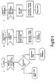
- the DBC 20 is shown in Figure 4 is a discrete unit having an input port 30 for receiving asynchronously transmitted data cells, an output for feeding data cells onto a switch 12 or 16 (see Figures 1 and 2 ) forming part of the switching network 10.
- the unit also has another input 34 for receiving messages back from the switch 12 or 16 and a feedback output 35 for transmitting feedback messages to the end-system 14 (shown in Figure 1 ).
- Figure 4 can be regarded as a functional diagram representing a subset system of a larger data processing unit, much of which may be embodied as software functions.
- Incoming cells on input 30 arrive as a user cell stream which is fed firstly to an activity detector 36.
- the purpose of the activity detector is to provide state information to a controller module 38 about each received transmission, each transmission being identified by its VPI and VCI contained in the cell headers.
- a transmission is labelled active by the activity detector 36 if it was previously quiet and a cell having the appropriate VPI and VCI values is observed to be transmitted from an end-system to input 30. Synchronisation of the activity detector 36 with the start of a cell header may be carried out using an error check field contained in the cell header.
- a transmission is considered to be in an inactive state if it was previously active and no cell having the appropriate VPI and VCI values has been detected for a period of time t.
- the error check field provides a degree of redundancy, by which error checking may be performed on the header information.
- the principal reason for providing the header error check field is to ensure that the header information is correct, thereby ensuring that cells are not transmitted to erroneous addresses.
- Activity detector 36 maintains a timer and state table for each VPI/VCI value pair.
- t is set to be several seconds so that active-inactive-active transitions relating to any given VPI/VCI value pair which are of the order of several milliseconds remain undetected so that the transmission is indicated as remaining in the active state under these conditions. This has the effect of reducing the frequency of messages sent by the DBC 20 to the CAC 18 at some expense to lowering utilisation of the network.
- Another function of the activity detector 36 is that of counting the cells for transmission during an interval after receiving a "start cell count" signal from the controller 38. This information can be used, for example, for charging purposes and also by the controller 38 for assessing the actual cell rate of received transmissions.
- the activity detector 36 reads the VPI/VCI values in each cell header of the arriving cell stream, and this information is used to update the state table which it maintains for each VPI/VCI value pair. As far as communication with the controller 38 is concerned, the detector 36 informs the controller of a change of state of any VPI/VCI value pair. The controller can inform the activity detector of the timer value t to be used. Preferably, the same value of t is used for all VPI/VCI value pairs. Cell count information is sent to the controller 38 by the activity detector 36 at the end of each timer expiry.
- the cells of the user cell stream arriving on input 30 are transmitted without delay to a buffer module 40 where they are stored in first-in, first-out (FIFO) buffer queues, each queue comprising cells having a given VPI/VCI value pair.
- the detector 36 is non-specific to cell type. Thus, the arrival of any data cells will be detected and can potentially affect the activity state associated with a VPI/VCI value pair, independently of the existence or absence of control or management cells.
- Buffered cells are fed from the buffer 40 to a shaper multiplexer module 42 prior to being fed to an ATM switch via output 32. Operation of the buffer and shaper/multiplexer modules 40, 42 will be described in more detail below.
- the buffer module is capable of signalling to the controller 38 when any buffer queue has reached a predetermined buffer fill threshold.
- the shaper multiplexer module 42 is responsible for removing cells from the buffer module 40 and transmitting them onwards towards their destination. It includes a multiplexer function and the shaper stores an CR value for each VPI/VCI value pair so that the cell stream fed from the output is shaped to ensure that the capacity of the respective path through the network for each transmission, as determined by the allocated bandwidth, is not exceeded.
- the controller 38 also controls a feedback module 44 for receiving feedback messages from the network on input 34 and from the controller 38 itself, for onward transmission to the end-system 14 via output 35.
- the functions of the buffer, shaper/multiplexer, and feedback modules 40, 42 and 44 will be described in more detail below. The controller 38 will be considered first.
- the purpose of the controller 38 is to signal to the CAC that an ABR type transmission identified by any given VPI/VCI value pair should have bandwidth in the system allocated or re-negotiated.
- the controller 38 sends a halt signal to the end-system via the feedback module 44 as soon as the activity detector 36 detects that the end-system has become active.
- the CAC 18 is then sent a request for bandwidth. This is interpreted by the CAC 18 as a request for the predetermined bandwidth associated with the end-system. If this bandwidth cannot be granted, the end-system is kept in a halt state, the cells already received by the DBC are buffered (by setting the shaper module 42 rate to zero) and a timer is started for monitoring for how long the cells are buffered.
- the CAC 18 periodically (preferably at periods just less than the maximum time for which cells are buffered by the shaper) attempts to find the requested bandwidth and offers it to the DBC, which in turn offers it to the end-system in the form of a signal via the feedback module 44.
- the end-system 14 takes up the offer of bandwidth, the bandwidth is allocated, and the shaper is notified of the CR corresponding to the allocated bandwidth.
- the CAC 18 may remove bandwidth allocation from other end-systems to obtain sufficient bandwidth to be allocated. Suitable bandwidth balancing techniques for use in the CAC, are described below.
- the end-system knows that the cells have been deleted since it also has a timer and unless a CR is fed-back within a predetermined time, it assumes that bandwidth cannot be allocated and that the few cells which were sent before the halt signal was received, have been deleted.
- the CAC 18 needs to remove the bandwidth, the whole bandwidth is removed and the end-system is halted as described above.
- the CAC 18 may continuously poll end-systems to offer bandwidth (to the predetermined level required by an end-system) to the end-system via the DBC. If the end-system starts transmitting, the bandwidth is allocated.
- This polling, offer and acceptance procedure may also be used to cause transmission to re-start after an end-system has been halted as described above.
- the controller 38 is also arranged to receive a signal from the buffer module 40 when the buffer fill for a given VPI/VCI value pair has reached a given threshold. This signal causes the controller 38 to command the feedback module 44 to issue a so-called resource management (RM) cell, which will be described in more detail hereinafter.
- the controller 38 may also receive a DBC identity value for each new transmission (identified by a new VPI/VCI value pair) which is established, this DBC identity value being received from the CAC. Alternatively, the DBC may use a default identity if none is supplied.
- SDLs for the controller are shown in Figures 6-1 and 6-2 .
- the controller 38 is arranged to write a DBC, VPI/VCI identity value pair into the feedback module 44. It is also arranged to instruct the feedback module 44 to issue a resource management command for a specific VPI/VCI value pair.
- This instruction may also contain an appropriate CR pair T, ⁇ , (T is an average cell inter-arrival time and ⁇ is a burst tolerance). It should be noted that only one change in the values specified in an RM cell is sent for each new VPI/VCI value pair whenever the CAC updates the CR value. Typically, this may be once every 30 seconds or more in a public network, and depends upon the sensitivity setting of the activity detector in the DBC 20. It follows that the required feedback control bandwidth can be relatively small.
- the controller 38 receives signals from the buffer module 40 whenever a buffer fill threshold is reached by cells having a specific VPI/VCI value pair.
- the feedback module 44 transmits current CR values (as signalled by the controller 38) to the end-system via output 35.
- the CR is transmitted using a resource management cell as shown in Figure 7 .
- one field of this cell is the DBC identity value which is used to enable an end-system 14 (see Figure 1 ) to distinguish between CR advices from different DBCs (e.g. DBCs 20-1 and 20-2 as shown in Figure 2 ) in the end-system to end-system path.
- This DBC identity field is indicated as field 50 in Figure 7 .
- the CR is placed in field 52.
- This RM cell like other cells, has a five octet header which contains a PT field 54 indicating that the cell is a resource management (RM) cell.
- RM resource management
- DBC identify values are not fixed but are chosen at the time of setting up the transmission path through the network for a given a VPI/VCI value pair.
- the CAC 18 assigns a value for the DBC identity for each VPI/VCI value pair
- the feedback module 44 maintains a table of (DBC, VPI/VCI) identity pairs.
- public network 10-1 is arranged to choose a DBC identity for a given VPI/VCI pair and signals this information forwards so that public network 10-2 does not chose the same value (e.g. public network 10-1 assigns identity 1, public network 10-2 assigns identity 2, etc).
- the DBC identity value is stored in a table maintained by the feedback module 44.
- the CR field 52 in the RM cell contains the CR advice from the CAC which is provided as the average cell inter-arrival time T, plus a burst tolerance ⁇ .
- Operation of the feedback module 44 is triggered by the controller 38 (a) when a new CR is advised by the CAC 18,and (b) when the buffer fill level in buffer module 40 corresponding to any VPI/VCI value pair rises above the buffer fill threshold.
- a resource management (RM) cell is then sent to the end-system.
- the pseudocode for the feedback module 44 is as follows and the corresponding SDL is shown in Figure 8 .
- the buffer module is shown in more detail in Figure 9 . Its purpose is to store incoming data cells on the basis of the VPI/VCI value pairs contained in the cells. Buffering the cells allows an end-system 14 ( Figure 1 ) time to respond to a feedback signal from module 44. Another function of the buffer module 40 is to send a signal to the controller 38 when the buffer fill threshold is reached, indicating that an end-system is not responding to a feedback signal (this in turn causes the controller 38 to re-send a CR to the end-system, as mentioned above). The buffer module 40 also drops received cells when the maximum buffer allocation for a given VPI/VCI value pair is exceeded. This is done by buffer overflow.
- the size of buffer.required for a DBC 20 controlling access to the switching system 10 could be relatively small. For example, if the DBC 20 has a combined input rate from all sources of 150 Mbit/s, then, if the round trip delay to the end-system is 100 ⁇ s, there will be less than 35 cells in flight whenever the CR values are changed.
- the size of the shared memory area 56 is mainly to cater for changes in the burst tolerance, because a change in this rate leads to only a small number of excess cell arrivals (e.g. around 35 cells).
- the fixed cell positions assigned to respective VPI/VCI value pairs are designated by the reference numeral 58 in Figure 9 .
- the cells in these positions represent the front cells of a plurality of queues, each queue having its own VPI/VCI value pair.
- the queues can be visualised as running horizontally in Figure 9 with the front cells at the right hand side.
- Cells arriving in the buffer module 40 are placed in the queues in a first-in, first-out (FIFO) order.
- the shaper/multiplexer module 42 operates to remove cells from the buffer module 40 and to transmit them onwards towards their destination via the network switches.
- Module 42 has two parts which are a multiplexer 60 and a shaper 62.
- the shaper 62 maintains a sustained cell rate (CR) value and a timer.
- CR sustained cell rate
- the cell stream fed to output 32 is shaped by the shaper so that bursts which are not greater than the burst tolerance ⁇ pass without being delayed by the shaper 62.
- the multiplex function may delay a cell if several transmissions represented by different VPI/VCI value pairs are bursting simultaneously.
- the multiplexer 60 assigns each active VPI/VCI value pair a fair share of the DBC output bandwidth. It does this by polling active VPI/VCI value pairs in a round-robin fashion. Cells which are waiting for a period equal to or greater than the rate interval T are flagged with a higher priority "cell must go" value.
- the multiplexer picks up these cells first (see Figure 11 ). Cells will be forced to wait by the shaper function if bursts arrive which are longer than the burst tolerance credit value.
- the detailed operation of the shaper/multiplexer module 42 will become apparent from the following pseudocode:-
- the CAC 18 When the CAC 18 receives a bandwidth request from the controller 38, it must first determined whether sufficient bandwidth is available to meet the predetermined minimum bandwidth. If sufficient bandwidth is not available by the time the timer for monitoring how long calls have been buffered, is about to expire, bandwidth is "robbed" from other users as described below. Confirmation of allocated bandwidth is then sent to the controller 38 which forwards the bandwidth allocation to the end-system via the feedback module 44.
- the first strategy involves a relatively simple connection admission control method which involves no actual rebalancing.
- a newly active transmission (VPI/VCI value pair) is given a single sustained cell rate (CR) which is retained until the transmission goes quiet again. Only when it is subsequently reactivated will the transmission get a different CR. This means that a quiet signal relating to one VPI/VCI value pair will cause no control signals to be generated for other VPI/VCI value pairs which were sharing capacity with it.
- This is combined with a filling method which involves (i) giving a first newly active connection an effective capacity which is half of the total available capacity; (ii) giving the next newly active connection an effective capacity which is half of the remaining capacity; (iii) giving the next newly active connection an effective capacity which is half of the still remaining capacity; and so on.
- This method is applied link-by-link over the entire route identified by the VPI/VCI value pair, and whichever yields the lowest effective capacity is the determinant of the CR fed back to the DBC 20.
- the DBC 20 is designed such that a user can only maintain a large effective capacity on the network so long as the VPI/VCI value pair remains in the active state in the activity detector 36 ( Figure 4 ), and the cell rate generated by the customer is close to the effective bandwidth value (refer to the cell-counting function of the activity detector described above), it follows that users can only hold onto large effective bandwidths for as long as they are prepared to be charged for the proportionally larger loads which they are submitting.
- This method is fair to users in the sense that, over a sufficiently long period, no user is systematically given a poorer capacity.
- the underlying principle is that, if an active signal causes control signals for other VPI/VCI value pairs, let the signal be limited to only one per link, namely the richest (largest capacity) VPI/VCI value pair. This can be described as a limited rebalancing method or a "take-only-from-the-richest" (Robin Hood) method.
- the above process is repeated link-by-link. Whichever link yields the lowest effective capacity is the determinant of the CR value sent back to the DBC. Now, using this value of effective capacity, the CAC assigns it link-by-link by taking half of the remaining capacity on that link, and any extra which is needed is taken from the richest VPI/VCI value pair on that link. Consequently, this generates at most one additional CR control message per link for each VPI/VCI active signal sent to the network. A quiet signal still generates no additional control messages.
- a dynamic bandwidth controller controls the application of data cells to an input port of the system, the data cells being supplied by a number of transmitting end-systems.
- the DBC detects the presence of incoming cells and requests bandwidth from a CAC forming part of the system.
- the switching system stores a table associating a number of signal sources connected to the ingress with respective minimum transmission bandwidths and, preferably also, maximum delay times.
- the DBC sends a request signal for the relevant minimum bandwidth to the CAC and delays transmission of the cells until at least the minimum bandwidth is allocated. This delay is typically effected by send a cell rate indicator signal back to the input port for placing the source in a half mode. If no allocation of bandwidth has occurred before the respective maximum delay time, bandwidth is allocated by robbing bandwidth from other signal sources.
Abstract
Description
- This invention relates to a broadband switching system for the switching of asynchronously transferred data cells, and to a method of switching asynchronously transmitted data cells.
- Broadband switching networks for switching asynchronously transferred cells are known, in which a predetermined level of bandwidth is allocated to a transmission channel connecting a first customer to a second customer. In some of these known systems, a communications channel is provided over a significant period of time, effectively of the leased-line type, and manual measures are implemented in order to set up such a connection or to modify a connection according to the particular terminations and the level of traffic being conveyed. Consequently, it is usual for customers to incur a fixed rate charge as part of the overall charge for the connection, resulting in payment being made irrespective as to whether the connection is being used or not.
- Alternative systems have been proposed or are available. In particular, it is possible for connections to be established on a dial-up basis, requiring termination equipment to be provided with facilities for establishing connections by issuing signalling commands and responding to similar commands issued by the network.
-
European Patent 0 468 802 discloses a dial-up system which allows variation in the bandwidth assigned to a virtual circuit using additional signalling commands between termination equipment and the network. - The use of permanent circuits to support a private communications network is widespread. The demand for such circuits is expected to grow to include broadband rates above 2 Mbit/s, the circuits carrying traffic multiplexed from sources which are inherently bursty, possibly together with traffic which is transmitted at constant bit rates and is delay sensitive, such as voice transmission and constant bit-rate video.
- Asynchronous transfer mode (ATM) cells all have a fixed information field of forty eight octets which can carry customer traffic or customer-originating control information (signalling). These two types of data transmission are distinguished by setting virtual path (VP) and vertical circuit (VC) values in the cell headers. Another field provided in the ATM header is known as cell loss priority, which enables low priority cells to be distinguished from high priority cells. In the event of congestion, the low priority cells may be discarded first.
- For private circuits within an ATM based network, the desired route, the required bandwidth, and the quality of service (QOS) are set up using network management procedures. The private circuits are known as permanent virtual circuits (PVCs) because there is no actual physical circuit, only a VP/VC value or "label" which is associated with information stored in the switches to determine the route and preserve the bandwidth and QOS requirements.
- A disadvantage of all known permanent circuits is that the bandwidth remains assigned to the circuit, even when the customer has nothing to transmit. This means that the customer may have to pay higher charges than would be obtained if the bandwidth was only made available when needed. The assumption being made here is that charging is related to reserved bandwidth, and this is not necessarily correct in terms of the way public network operators may choose to charge for virtual circuits. However, it is expected that charging based on reserved bandwidth will become a significant factor in the future.
- A common practice is to set up a permanent virtual circuit so that it is only available during certain hours of the day, or during certain days of the week. Λ difficulty with this approach is that it does not allow the customer to change the pattern of usage quickly, and it may only crudely reflect the usage required by the customer.
- A second proposal has been to provide the customer with a separate communications channel to the network management plane, thereby allowing a permanent virtual circuit to be reconfigured. A difficulty with this approach is that some time delay will be incurred before the customer can start to use the virtual circuit.
- A third proposal is to introduce equipment at every switching point in the network that recognises a fast resource management cell, indicating that bandwidth should now be assigned to the circuit. A difficulty with this approach is that there is no internationally agreed standard for a bandwidth-requesting cell that would be recognised by the switching equipment produced by the various manufacturers.
- According to a first aspect of the present invention, there is provided a broadband switching system having at least one ingress for connection to a respective signal source and at least one egress for connection to a receiving system, the switching system further comprising at least one switch for transmitting information-carrying asynchronously transferred data cells from the ingress to the egress;
- system control means for accepting and establishing a connection between the ingress and egress via the said switch; and
- bandwidth control means arranged to feed an indicator signal back to the ingress for transmission to the signal source;
- said broadband switching system being characterised by:
- table storing means arranged for storing a table associating a predetermined bandwidth with the signal source;
- the bandwidth control means having means for recognising the source of the detected cells to identify the predetermined bandwidth associated with the detected cells, and the bandwidth control means being operable in response to the said cell detection periodically to examine the bandwidth available between the ingress and egress and whilst the predetermined bandwidth is unavailable to send a feedback signal to the ingress for receipt by the source to halt the supply of further cells by the source until the said predetermined bandwidth is allocated or re-allocated and means for sending a restart feedback signal to the ingress for receipt by the source to cause the source to restart the supply of cells to the ingress,
- said bandwidth control means being arranged to detect incoming cells supplied to ingress from the signal source, and, automatically in response to such cell detection, to cause the system control means to allocate said predetermined bandwidth for transmission of the cells to the egress.
- It will be appreciated that in practice, the automatic allocation of the predetermined bandwidth may occur some time after incoming cells are detected. This is because the required bandwidth may not immediately be available for allocation.
- A connection established in this way is particularly suitable for bandwidth sensitive transmissions such as data communications between networked personal computers. This is because if bandwidth is allocated, it will always be at least to the predetermined level. The above types of transmission do not operate satisfactorily when operating below the predetermined level of bandwidth (which is a pre-registered level that has been calculated as being sufficient for satisfactory operation) and thus if that level is not available, no bandwidth is allocated, i.e. lower bandwidth amounts are not allocated.
- However, in some circumstances the bandwidth control means may be arranged to cause allocation of bandwidth to a signal source at a level less than the predetermined bandwidth associated with that signal source and in conjunction with downgrading the priority of cells received at the ingress such that the bandwidth of non-downgraded cells supplied to the switch does not exceed the allocated bandwidth. This will typically occur when the predetermined level of bandwidth is no longer available on the system.
- Once the cells have been downgraded, the system may delete the cells if the system becomes overloaded i.e. has more cells for transmission than can be transmitted in the available bandwidth on the system. Thus the user is taking a conscious risk that some of a message may not be transmitted when transmitting in this optional priority-downgrading mode. Conveniently, the cell deletion technique used is an "intelligent" technique which does not randomly delete cells (thereby corrupting an unknown number of messages) but deletes cells wherever possible, only from a single message.
- The bandwidth control means may include feedback means arranged to transmit a cell rate value derived from a bandwidth-indicating signal provided by a stored table associating fixed bandwidth levels with signal sources. The stored table be located in the system control means and/or the bandwidth control means. The cell rate value is fed back to the ingress for transmission to a recognised signal source to indicate to the signal source a permitted rate of supply of cells to the ingress.
- The feedback means may also be arranged to transmit a "predetermined bandwidth not available" signal to the ingress when the system control means determines that system needs to operate in the priority-downgrading mode for a signal source. Having received such a signal, a signal source may choose to take advantage of the opportunity of transmitting at a lower priority (with the risk of lost cells) but at the same rate as before or to cease transmitting until a subsequent opportunity exists two transmit at the predetermined level (without cells being downgraded in priority).
- Preferably, the bandwidth control means is arranged automatically to cause the system control means to deallocate bandwidth for cells from a particular signal source when that signal source is determined to be inactive. This may be when the rate of supply of cells received at the ingress is zero.
- The system control means may be arranged periodically to determine whether the predetermined bandwidth is available on the system. The bandwidth controller may then "offer" the predetermined bandwidth so determined, to a signal source preferably using the indicator signal. The offer may be made to a signal source which has been halted because it has had its bandwidth deallocated or it may be offered to a signal source which is inactive. Preferably, the system control means determines that the offer has not been accepted by recognising that the bandwidth has not be caused to been allocated within a predetermined acceptance time period.
- Conveniently, the bandwidth control means are arranged to detect the rate at which cells are supplied to the input port of the network, primarily to determine whether or not cells are being supplied.
- The bandwidth control means may include a buffer for delaying transmission of the cells to the switch until bandwidth has been allocated for the cells.
- Preferably, the feedback means is arranged to transmit a reduce-traffic-level instruction to the ingress for reception by a signal source, when receipt of cells from a signal source has been detected and no bandwidth has been allocated for cells from that signal source. The reduce-traffic-level instruction may be a halt instruction for instructing a signal source to cease supplying cells to the ingress. The bandwidth control means may also include timing means for measuring the period of time for which the cells are delayed and may include cell deletion means for deleting cells from the buffer after they have been delayed for a predetermined period of time. A signal source may be arranged to allow for this to occur if it has not received a cell rate value informing it that the predetermined bandwidth has been allocated.
- Buffering may be used on other occasions when an signal source is transmitting at a higher rate than the rate capable of being accepted by the network at a given time. Indeed, it is preferable for the buffer to have means for detecting when it is filled to a predetermined threshold level, the feedback means being responsive to the detection to cause a cell rate value (usually requesting the signal source to halt transmission) to be transmitted to the signal source, the signal source having the ability then to stop its output to avoid buffer overflow and a consequent loss of data.
- An activity detector forming part of the bandwidth control means may include a cell counter for counting cells received from respective signal sources coupled to the bandwidth control means. The cell count so obtained, may be used to generate charging signals for customer billing and for other purposes.
- The invention also includes, according to a second aspect thereof, a method as claimed in claim 13 of the accompanying claims. Third and fourth aspects of the invention are set out in accompanying
claims 16 and 17. - The invention will now be described in greater detail, by way of example, with reference to the accompanying drawings, in which:-
-
Figure 1 is a diagram of a broadband switching system in accordance with the invention; -
Figure 2 is a diagram of another broadband switching system in accordance with the invention; -
Figure 3 is a diagram of part of a broadband switching system showing how a single bandwidth controller can be shared by several end-systems; -
Figure 4 is a block diagram of a bandwidth controller for use in the systems ofFigures 1 and 2 ; -
Figure 5 is a specification description language diagram (SDL) for the activity detector module shown inFigure 4 ; -
Figures 6-1 and6-2 are SDLs for the controller module ofFigure 4 ; -
Figure 7 is a diagram of a resource management (RM) data cell; -
Figure 8 is an SDL for the feedback module ofFigure 4 ; -
Figure 9 is a diagram of a buffer for the bandwidth controller ofFigure 4 ; -
Figure 10 is an SDL for the buffer; -
Figure 11 is a block diagram of a shaper/multiplexer module and its connection to the buffer ofFigure 6 ; -
Figures 12-1, 12-2, and 12-3 are SDLs for the shaper/multiplexer module; - In its preferred form, the invention is concerned with a broadband switching network which may form part of or may constitute a public switching network for the transmission of asynchronously transferred data cells between end-systems.
- Referring to
Figure 1 , thepublic network 10 has a plurality of switches operable in asynchronous transfer mode (ATM). In this simple example, the switches include twolocal switches 12 each having a port for connection to a respective end-system 14, and atransit switch 16 interconnecting the local switches 12. Associated with the switches is a connection admission control function (CAC) 18 and a dynamic bandwidth controller (DBC) 20 for controlling traffic entering the network through one of the local switches 12. Thisswitch 12 also includes a usageparameter control device 22 for dynamically altering the priority of data cells received at theinput port 24 of the network from the end-system 14. - It will be understood that, in practice, the
network 10 will include large numbers of local andtransit switches several DBCs 20 all interconnected to form a network having a plurality of ports such asport 24 for connecting several end-systems such as end-system 14. Using theDBC 20, thepublic network 10 is able to provide an available bit rate (ABR) service, the DBC acting to detect incoming cells supplied to theinput port 24 and, automatically in response to this detection, to cause theCAC 18 to allocate bandwidth for the transmission of the cells to the destination end-system. Generally, end-systems 14 requiring the ABR service are allocated to a fixedDBC 20. There may be more than oneDBC 20 for eachlocal ATM switch 12. In the case of a fault, end-systems can be rerouted to a standby DBC (not shown). - Data is transmitted in the form of asynchronous transfer mode (ATM) cells, each having an information field of forty-eight octets, in addition to a header of five octets, which includes information facilitating transmission through the network itself. Thus, routing is controlled on a cell-by-cell basis and a plurality of transmission paths and time multiplexed slots may be employed for any particular link. ATM cells are, therefore, transmitted via virtual paths and virtual circuits, as defined by the header information.
- The virtual paths and virtual circuits are identified by a virtual path identifier (VPI) and a virtual channel identifier (VCI) in the five octet header which effectively defines the connection between the end-systems so that cells forming part of a common message will be transmitted over the same connection. ABR traffic enters the
public network 10 by routing cells according to their VPIs and VCIs through theDBC 20 and then out to external routes, as shown inFigure 1 . From theDBC 20, the traffic on each virtual path and virtual channel is restricted to a cell rate (which will be referred to hereinafter as "CR") determined by theCAC 18. - An alternative illustrative arrangement is shown in
Figure 2 . In this case, end-system 14A is subject to the control of more than one DSC. In fact, the connection between two end-systems system 14A of the current applicable CR. - In the systems of both
Figure 1 and Figure 2 , theDBCs 20, 20-1, 20-2 request bandwidth from therespective CAC 18, 18-1, 18-2 whilst buffering any incoming data cells which cannot immediately be transmitted to therespective switches CAC 18, 18-1, 18-2 then allocates a bandwidth. This allocation is then indicated to theDBC 20, 20-1, 20-2 which communicates a maximum CR to the transmitting end-system 14. The allocation only occurs if sufficient bandwidth is available on the system to allocate a predetermined bandwidth (pre-registered by the customer) to the end-system. - It is possible for a single dynamic bandwidth controller (DBC) to be shared by several end-systems or signal sources. For example, referring to
Figure 3 , a DBC 20-3 is shown connected to a broadband ATM switch 12-3 forming part of thenetwork 10, the traffic of threesources 14C being handled using anoutput buffer 28. The number of sources which can be handled by the DBC 20-3 is determined by the link rate L (i.e. there must be not so many sources that it is always the link rate L which is the limiting factor determining the available rate.) The aggregate cell rate of the ABR traffic from thesources 14C must not exceed L. This implies that if the traffic from each source is bursty, there may be times when theoutput buffer 28 is congested. This can be avoided by supplementing the sustained cell rate (CR) feedback to the end-systems 14C with generic flow control (GFC) signals which operate to stop all transmissions from each source immediately. - Whenever the dynamic bandwidth controller (DBC) is incorporated in the arrangements of
Figures 1, 2 , or3 , its main functions are as follows. - Firstly, it provides buffering of incoming data cells, the degree of buffering at any given time being determined according to the transmission containing the cells, the transmission being identified by the VPI and VCI information referred to above. The DBC further controls or "shapes" the traffic fed to the
network 10 so as to be equal to the current CR applicable to that particular transmission, the CR depending on the allocated bandwidth. - The allocated bandwidth, and hence the CR, for any given transmission is determined by the CAC 18 (see
Figure 1 ) on the basis of determining the route to be followed by the transmission and assessing a fair share of the available capacity on the route based upon the known number of active transmissions and on the predetermined bandwidth which needs to be allocated. - When a transmission begins it is detected in the DBC, which immediately transmits a halt signal to the relevant end-system 14 (see
Figure 1 ). The halting of the end-system ensures that a newly active transmitting source does not cause overload in thesystem 10 before theCAC 18 has been able to allocate bandwidth and derive an CR for that transmission. Such overload would typically cause cell loss for that transmission. This is part of a second main function of the DBC, i.e. to send a feedback signal to the end-system for the purpose of controlling its transmitted cell rate. Indeed, each time theCAC 18 derives a new CR for a transmission, a CR advice signal is fed back to the end-system. In this case, the CR will be either zero (i.e. halt) or a CR corresponding to the predetermined bandwidth for the end-system 14. - The pre-transmission buffering of the DBC is used to allow a cooperating end-system sufficient time to adjust its output to the latest CR feedback advice. This implies that there is sufficient buffering in the DBC to allow excess cells to enter for a period at least equal to the round trip delay between the DBC and the end-system. If cells continue to arrive from the end-
system 14 at a rate greater than the advised feedback CR (for instance, because the CR was lost en route, or because of a faulty end-system) the excess cells will be dropped in the DBC by overflow of the buffer. - In the preferred DBC, it is also possible to include fault tolerance by making use of a buffer threshold. When the stored cells relating to a given transmission reach the threshold, retransmission of the CR advice feedback to the end-system is triggered. This feature is useful also as a mechanism for policing end-systems to prevent inefficient use of bandwidth, whether due to a faulty terminal or due to deliberate non-compliance with contracted transmission rules. In this way, interference with the quality of service provided for other, compliant end-systems is prevented. In effect, the DBC defines the ABR traffic contract with the
network 10. - The modules of the
DBC 20 will now be described in more detail with reference toFigure 4 . - The
DBC 20 is shown inFigure 4 is a discrete unit having an input port 30 for receiving asynchronously transmitted data cells, an output for feeding data cells onto aswitch 12 or 16 (seeFigures 1 and 2 ) forming part of theswitching network 10. The unit also has anotherinput 34 for receiving messages back from theswitch feedback output 35 for transmitting feedback messages to the end-system 14 (shown inFigure 1 ). Although theDBC 20 is shown as a discrete unit, it will be appreciated thatFigure 4 can be regarded as a functional diagram representing a subset system of a larger data processing unit, much of which may be embodied as software functions. - Incoming cells on input 30 arrive as a user cell stream which is fed firstly to an
activity detector 36. The purpose of the activity detector is to provide state information to acontroller module 38 about each received transmission, each transmission being identified by its VPI and VCI contained in the cell headers. A transmission is labelled active by theactivity detector 36 if it was previously quiet and a cell having the appropriate VPI and VCI values is observed to be transmitted from an end-system to input 30. Synchronisation of theactivity detector 36 with the start of a cell header may be carried out using an error check field contained in the cell header. A transmission is considered to be in an inactive state if it was previously active and no cell having the appropriate VPI and VCI values has been detected for a period of time t. The error check field provides a degree of redundancy, by which error checking may be performed on the header information. Thus, the principal reason for providing the header error check field is to ensure that the header information is correct, thereby ensuring that cells are not transmitted to erroneous addresses. -
Activity detector 36 maintains a timer and state table for each VPI/VCI value pair. Preferably, t is set to be several seconds so that active-inactive-active transitions relating to any given VPI/VCI value pair which are of the order of several milliseconds remain undetected so that the transmission is indicated as remaining in the active state under these conditions. This has the effect of reducing the frequency of messages sent by theDBC 20 to theCAC 18 at some expense to lowering utilisation of the network. - Another function of the
activity detector 36 is that of counting the cells for transmission during an interval after receiving a "start cell count" signal from thecontroller 38. This information can be used, for example, for charging purposes and also by thecontroller 38 for assessing the actual cell rate of received transmissions. - Pseudocode for the activity detector is listed below and the corresponding SDL appears in
Figure 5 .
      BEGIN {cell arrival}
         cell arrival from end-system
         read VC
         reset VC inactivity timer
         IF VC is newly active THEN
           update state table
           advise CONTROLLER of newly active VC
         ELSE IF counting cells(VPI/VCI) THEN
           increment cell.count(VPI/VC1)
         ELSE
           do nothing
      END
      BEGIN {VC timer expires}
         VC inactivity timer expires indicating quiet VC
         update state table
         advise CONTROLLER of quiet VC
         counting cells :=FALSE
      END
      BEGIN {receive a start.cell.count signal}
         receive a start.cell.count(VPI/VCI) signal from CONTROLLER
         cell.count(VPI/VCI) : =0
         counting cells :=RUE
      END
      BEGIN {cell.count timer expires}
         cell.count timer expires
         send cell.count(VPI/VCI) to CONTROLLER
         restart cell.count timer
     END
     BEGIN {receive an active VPI/NCI from ACTIVITY DETECTOR}
       receive active (VPI/VCI) from ACTIVITY DETECTOR
        send halt (VPI/VCI) to feedback
        send bandwidth request (VPI/VCI) to CAC
        send active (VPI/VCI) and CR=0 to shaper
        start timer for buffered cells
     END
        BEGIN {timer expires}
           timer for buffered cells expires
           send delete buffered cells (VPI/VCI) to shaper
        END
        BEGIN {receive a CR from CAC}
           receive a CR from CAC
           send CR to shaper
           send CR to feedback
        END
        BEGIN {receive an inactive signal}
           receive an inactive signal
           advise CAC of inactive VPI/VCI
        END
        BEGIN {receive a VPI/VCI buffer threshold signal}
          receive a VPI/VCI buffer threshold signal
          signal feedback to retransmit CR to end-system
        END
      BEGIN {Receive a CR}
         receive a CR for a VPI/VCI from Controller
         default_CR: = CR
      END {receive an CR}
      BEGIN {RM.cell timer expires}
         RM.cell timer expires
         create RM.cell
        write default.CR into RM.cell
         send RM.cell to end-system
       restart RM.cell timer
      END {cell arrival from network}
     BEGIN (Receive a cell)
        receive a cell
        IF there is room in the buffer THEN
          put ceU in buffer
          increment buffer-fill level
       IF buffer-full level = Threshold THEN
               transmit buffer-full signal to CONTROLLER
        ELSE
               do nothing
     END {Receive a cell}
     BEGIN {receive a fetch}
        receive a VPI/VCI fetch signal from the SHAPER/MUX
        pass cell from buffer to the SHAPER/MUX
        decrement buffer-fill level
     END {Receive a fetch}
  1. BEGIN {STATE =ACTIVE}
          receive a cell.waiting[VPI/VCI] signal from buffer
          IF burst credit ok THEN
            cell.can.go:= TRUE
            STATE: = WAIT for multiplexer
          ELSE {burst credit not ok}
            STATE :=WAIT for credit timer to expire
       END
  2 BEGIN {STATE =WAIT for credit timer to expire}
          credit timer expires
          increment burst tolerance credit counter
          cell can go :=TRUE
          cell.must.go : =TRUE
         STATE := WAIT for multiplexer
       END
  3 BEGIN {STATE = WAIT for multiplexer}
          receive a fetch.cell[VPI/VCI] from multiplexer
         decrement credit counter
        cell.can.go : =FALSE
        cell.must.go : =FALSE
        STATE: =ACTIVE
      END
 4. BEGIN {STATE =WAIT for multiplexer}
        credit timer expires
        IF credit counter <: THEN
           increment credit counter
        ELSE
           do nothing
      cell.must.go : =TRUE
      END
 5. BEGIN {STATE =SHAPER ACTIVE}
        credit timer expires
        IF credit counter <: THEN
           increment credit counter
        ELSE
           do nothing
        cell.must.go : =TRUE
      END
 6. BEGIN {STATE =SHAPER.CR ACTIVE}
        new CR advised (T,τ)
        nextT: = T
        next credit: = τ
      END
 7. BEGIN {STATE =SHAPER TIMER ACTIVE}
        timer expires
        reset timer (nexT)
      END
 8. BEGIN {STATE =MULTIPLEXER ACTIVE}
        output ceU timer expires
        index :=pointer
        REPEAT {1st loop of searching for cell.must-go}
           increment index
           IF cell.must.go[index] THEN
             pointer:= index
             fetch cell[index] from buffer
             send fetch cell signal to SHAPER
             STATE :=MUX.ACTIVE
           ELSE
             IF index =max.buffer.size THEN
                index : =0
        UNTIL index =pointer
        REPEAT {2nd loop of searching for cell.can.go}
           increment index
           IF cell.can.go[index] THEN
             pointer:= index
             fetch cell[index] from buffer
             send fetch cell signal to SHAPER
             STATE :=MUX.ACTIVE
              ELSE
                IF index =max.buffer.size THEN
                  index : =0
           UNTIL index = pointer
           send no.cell.waiting.signal
        END
- (i) the first newly active VPI/VCI value pair is assigned an effective capacity equal to half of the total available capacity;
- (ii) the next newly active connection is assigned half of the remaining capacity plus a fifth of the effective capacity of the first VPI/VCI value pair (i.e. the current richest);
- (iii) the next newly active connection is assigned half of the remaining capacity plus one fifth from the current richest; and so on.
- (i) the first newly active VPI/VCI value pair gets 50 Mbit/s and there is 50 Mbit/s remaining;
- (ii) the next VPI/VCI value pair gets half of the remainder (which yields 25 Mbit/s) plus a fifth from the first, which means that the first now has 40 Mbit/s, and the second has 35 Mbit/s;
- (iii) the next VPI/VCI value pair gets half of the remainder, which yields 12.5 Mbit/s plus a fifth from the first, so that the first now has 32 Mbit/s, the second still has 35 Mbit/s, the third has 20.5 Mbit/s, and so on.
Claims (15)
- A broadband switching system (10) having at least one ingress (24) for connection to a respective signal source (14) and at least one egress for connection to a receiving system, the switching system further comprising:at least one switch (12) for transmitting information-carrying asynchronously transferred data cells from the ingress (24) to the egress;system control means (18) for accepting and establishing a connection between the ingress (24) and egress via the said switch (12); andbandwidth control means (20) arranged to feed an indicator signal back to the ingress (24) for transmission to the signal source (14);said broadband switching system (10) being characterised by:table storing means arranged for storing a table associating a predetermined bandwidth with the signal source (14);the bandwidth control means (20) being arranged to detect incoming cells supplied to ingress (24) from the signal source (14), and, automatically in response to such cell detection, to cause the system control means (18) to allocate said predetermined bandwidth for transmission of the cells to the egress;said bandwidth control means (20) having means for recognising the source (14) of the detected cells to identify the predetermined bandwidth associated with the detected cells, and the bandwidth control means (20) being operable in response to the said cell detection periodically to examine the bandwidth available between the ingress (24) and egress and whilst the predetermined bandwidth is unavailable to send a feedback signal to the ingress (24) for receipt by the source (14) to halt the supply of further cells by the source (14) until the said predetermined bandwidth is allocated or re-allocated and means for sending a restart feedback signal to the ingress (24) for receipt by the source (14) to cause the source (14) to restart the supply of cells to the ingress (24).
- A system according to claim 1, characterised in that the indicator signal is a cell rate indicator signal.
- A system according to claim 2, characterised in that the bandwidth control means (20) is arranged to delay cells initially received from the source (14) at the start of the transmission and then subsequently to cause the said allocation of the predetermined bandwidth.
- A system according to claim 3, characterised in that the table also associates a maximum transmission delay time with the signal source (14), and in that the bandwidth control means (20) is arranged to cause the system control means (18) to allocate the said predetermined bandwidth at least before the end of the said maximum delay time and, in conjunction therewith, to feed the said cell rate indicator signal with a cell rate commensurate with the allocated bandwidth to the ingress (24) for transmission to the signal source (14).
- A system according to claim 1, wherein the bandwidth control means (20) is arranged to cause allocation of bandwidth to a signal source (14) at a level less than the predetermined bandwidth associated with that signal source (14) and is further arranged to downgrade the priority of cells received at the ingress (24) such that the bandwidth of non-downgraded cells supplied to the switch (12) does not exceed the allocated bandwidth
- A system according to claim 2 characterised in that the bandwidth control means. (20) includes feedback means (44) arranged to transmit a maximum cell rate value to the ingress (24) for transmission to a recognised signal source (14) to indicate to the signal source (14) a maximum permitted rate of supply of cells to the ingress (24).
- A system according to any preceding claim, characterised in that the bandwidth control means (20) is arranged automatically to cause the system control means (18) to deallocate bandwidth for cells from a particular signal source (14) when that signal source (14) is determined to be inactive.
- A system according to any preceding claim characterised in that the bandwidth control means (20) includes a buffer (40) for delaying transmission of the cells to the switch (12) until bandwidth has been allocated for the cells.
- A system according to claim 6, characterised in that the feedback means (44) is arranged to transmit a halt instruction to the ingress (24) for reception by a signal source (14) and for instructing a signal source (14) to cease supplying cells to the ingress (24) when receipt of cells from a signal source (14) has been detected and no bandwidth has been allocated for cells from that signal source (14).
- A system according to claim 4 characterised in the bandwidth control means (20) includes timing means for measuring the period of time for which the cells are delayed.
- A system according to claim 10 characterised by including cell deletion means for deleting cells from the buffer after they have been delayed for a predetermined period of time.
- A method of operating a broadband switching system (10) for transmitting information carrying asynchronously transferred data cells from a ingress (24) of the system to an egress of the system (10) via at least one switch (12), the method being characterised by:storing information associating a predetermined bandwidth with a signal source (14) connectible to the ingress (24); detecting incoming cells from the said source at the ingress (24), andautomatically in response to such detection, providing a request signal in the system for allocating the said bandwidth;selectively causing a delay in the transmission of the cells to the egress if the said predetermined bandwidth is not allocated in the system;subsequently allowing cell transmission when allocation occurs;deallocating the predetermined bandwidth when the available bandwidth falls below the predetermined bandwidth; andperiodically examining the available bandwidth to determine whether the predetermined bandwidth may be reallocated to the source (14).
- A method according to claim 12, characterised in that the delay is effected by transmitting a feedback signal to the ingress (24) for placing the signal source (14) in a halt mode.
- A method according to claim 13, characterised in that the feedback signal is a cell rate indicator signal.
- A broadband switching system (10) having at least one ingress (24) for connection to a respective signal source (14) and at least one egress for connection to a receiving system, the switching system further comprising:at least one switch (12) for transmitting information-carrying asynchronously transferred data cells from the ingress (24) to the egress;system control means (18) for accepting and establishing a connection between the ingress (24) and egress via the said switch (12); andbandwidth control means (20) arranged to feed a indicator signal back to the ingress (24) for transmission to the signal source (14);said broadband switching system (10) being characterised by:said bandwidth control means (20) being further arranged to detect incoming cells supplied to the ingress (24) from the signal source (14); andthe system being arranged in response to said cell detection automatically to determine that a predetermined bandwidth is available for transmission of cells from the source (14) to the egress, and to offer this bandwidth to the source (14) using the said indicator signal;the system being further arranged to deallocate and reallocate the bandwidth to the source (14) as the available bandwidth falls below and above predetermined bandwidth respectively.
Priority Applications (1)
| Application Number | Priority Date | Filing Date | Title |
|---|---|---|---|
| EP96904976A EP0813781B1 (en) | 1995-03-08 | 1996-03-08 | Broadband switching system |
Applications Claiming Priority (4)
| Application Number | Priority Date | Filing Date | Title |
|---|---|---|---|
| EP95301522 | 1995-03-08 | ||
| EP95301522 | 1995-03-08 | ||
| PCT/GB1996/000534 WO1996027964A1 (en) | 1995-03-08 | 1996-03-08 | Broadband switching system |
| EP96904976A EP0813781B1 (en) | 1995-03-08 | 1996-03-08 | Broadband switching system |
Publications (2)
| Publication Number | Publication Date |
|---|---|
| EP0813781A1 EP0813781A1 (en) | 1997-12-29 |
| EP0813781B1 true EP0813781B1 (en) | 2010-06-09 |
Family
ID=8221117
Family Applications (1)
| Application Number | Title | Priority Date | Filing Date |
|---|---|---|---|
| EP96904976A Expired - Lifetime EP0813781B1 (en) | 1995-03-08 | 1996-03-08 | Broadband switching system |
Country Status (12)
| Country | Link |
|---|---|
| US (1) | US6222823B1 (en) |
| EP (1) | EP0813781B1 (en) |
| JP (1) | JPH11501475A (en) |
| KR (1) | KR19980702937A (en) |
| CN (1) | CN1097912C (en) |
| AU (1) | AU718665B2 (en) |
| CA (1) | CA2214838C (en) |
| DE (1) | DE69638195D1 (en) |
| MX (1) | MX9706820A (en) |
| NO (1) | NO974132L (en) |
| NZ (1) | NZ302751A (en) |
| WO (1) | WO1996027964A1 (en) |
Families Citing this family (30)
| Publication number | Priority date | Publication date | Assignee | Title |
|---|---|---|---|---|
| GB2327317B (en) | 1997-07-11 | 2002-02-13 | Ericsson Telefon Ab L M | Access control and resourse reservation in a communications network |
| US6574222B1 (en) | 1998-02-20 | 2003-06-03 | Sprint Communications Company, L.P. | System and method for allocating bandwidth for a call |
| US6922409B1 (en) | 1998-02-20 | 2005-07-26 | Sprint Communications Company L.P. | System and method for allocating bandwidth for a call |
| US7079534B1 (en) * | 1998-02-20 | 2006-07-18 | Sprint Communications Company L.P. | System and method for allocating bandwidth for a call |
| US6735176B1 (en) * | 1998-03-26 | 2004-05-11 | Nortel Networks Limited | Dynamic bandwidth management and rerouting |
| US6377549B1 (en) * | 1998-06-30 | 2002-04-23 | U.S. Philips Corporation | Call admission control system for wireless ATM networks |
| FI108203B (en) | 1998-11-27 | 2001-11-30 | Nokia Mobile Phones Ltd | Method and apparatus for transmitting information in a packet radio service |
| GB2346501A (en) * | 1998-12-08 | 2000-08-09 | Nokia Telecommunications Oy | Controlling bandwidth in an asynchronous transfer mode network |
| JP3556495B2 (en) * | 1998-12-15 | 2004-08-18 | 株式会社東芝 | Packet switch and packet switching method |
| US6819656B2 (en) * | 1999-01-08 | 2004-11-16 | Hewlett-Packard Development Company, L.P. | Session based scheduling scheme for increasing server capacity |
| US7103068B1 (en) * | 1999-05-04 | 2006-09-05 | Sprint Communication Company L.P. | System and method for configuring bandwidth transmission rates for call connections |
| WO2001001634A1 (en) * | 1999-06-24 | 2001-01-04 | Fujitsu Limited | Dynamic virtual channel manager |
| US7016375B1 (en) * | 1999-07-07 | 2006-03-21 | Nortel Networks Limited | Integrated connection admission control and bandwidth on demand for a access asynchronous network |
| DE19945152C1 (en) * | 1999-09-21 | 2001-04-26 | Siemens Ag | Method and arrangement for coupling messages between a central control device and decentralized communication devices |
| US7283512B2 (en) * | 2000-01-20 | 2007-10-16 | Verizon Business Global Llc | Intelligent network and method for providing voice telephony over ATM and point-to-multipoint connectivity |
| US6765871B1 (en) * | 2000-11-29 | 2004-07-20 | Akara Corporation | Fiber channel flow control method and apparatus for interface to metro area transport link |
| WO2002103952A2 (en) * | 2001-06-14 | 2002-12-27 | Cariden Technologies Incorporated | Methods and systems to generate and implement a changeover sequence to reconfigure a connection-oriented network |
| US7386274B2 (en) * | 2002-04-15 | 2008-06-10 | Aol Llc, A Delaware Limited Liability Company | Wireless viral mesh network and process for using the same |
| US7392355B2 (en) * | 2002-07-09 | 2008-06-24 | International Business Machines Corporation | Memory sharing mechanism based on priority elevation |
| US7558869B2 (en) * | 2003-02-13 | 2009-07-07 | Nokia Corporation | Rate adaptation method and device in multimedia streaming |
| US7323342B2 (en) * | 2003-04-04 | 2008-01-29 | Exxonmobil Research And Engineering Company | Method for improving oil desalting by forming unstable water-in-oil emulsions |
| US7660239B2 (en) * | 2003-04-25 | 2010-02-09 | Alcatel-Lucent Usa Inc. | Network data re-routing |
| JP2005012260A (en) * | 2003-06-16 | 2005-01-13 | Matsushita Electric Ind Co Ltd | Data transmission control method |
| US7359405B2 (en) * | 2003-10-17 | 2008-04-15 | Asix Electronics Corporation Ltd. | Burst transfer mechanism of network packets having MAC frames over USB bus |
| CN101207505B (en) * | 2006-12-18 | 2010-05-19 | 中兴通讯股份有限公司 | Method for operating, maintaining , managing and looping for asynchronous transfer mode network cross-equipment |
| US7911948B2 (en) * | 2007-10-17 | 2011-03-22 | Viasat, Inc. | Methods and systems for performing TCP throttle |
| WO2009151863A2 (en) * | 2008-06-10 | 2009-12-17 | Myers Wolin, Llc | A network gateway for time-critical and mission-critical networks |
| JP5497529B2 (en) | 2010-05-13 | 2014-05-21 | 日本電気株式会社 | Network relay apparatus and QoS control method |
| US9036474B2 (en) * | 2010-06-08 | 2015-05-19 | Alcatel Lucent | Communication available transport network bandwidth to L2 ethernet nodes |
| US9608696B2 (en) | 2013-10-11 | 2017-03-28 | Qualcomm Incorporated | Dynamic transmit power and signal shaping |
Family Cites Families (27)
| Publication number | Priority date | Publication date | Assignee | Title |
|---|---|---|---|---|
| US5377327A (en) | 1988-04-22 | 1994-12-27 | Digital Equipment Corporation | Congestion avoidance scheme for computer networks |
| EP0413488B1 (en) | 1989-08-15 | 1997-03-05 | AT&T Corp. | Method for regulating traffic in a high speed data network |
| US5231631A (en) * | 1989-08-15 | 1993-07-27 | At&T Bell Laboratories | Arrangement for regulating traffic in a high speed data network |
| CA2038646C (en) | 1990-03-20 | 1995-02-07 | Katsumi Oomuro | Atm communication system with optimal traffic control by changing the allocated bandwidth |
| EP0452223A3 (en) | 1990-04-13 | 1994-06-08 | Digital Equipment Corp | Telecommunications network with plesiochronous transfer mode |
| JP2909165B2 (en) * | 1990-07-27 | 1999-06-23 | 株式会社東芝 | Broadband communication network, end user terminal, communication network, broadband communication node, communication node, interface adapter, multipoint connection interface, multipoint connection control device and access unit |
| JP2834293B2 (en) | 1990-08-17 | 1998-12-09 | 株式会社日立製作所 | How to change the virtual path capacity |
| DE69130853T2 (en) | 1990-11-21 | 1999-07-22 | At & T Corp | Bandwidth management and congestion protection for access to broadband ISDN networks |
| JP3278865B2 (en) | 1991-06-28 | 2002-04-30 | 日本電気株式会社 | Traffic control method |
| US5179556A (en) | 1991-08-02 | 1993-01-12 | Washington University | Bandwidth management and congestion control scheme for multicast ATM networks |
| US5291481A (en) | 1991-10-04 | 1994-03-01 | At&T Bell Laboratories | Congestion control for high speed packet networks |
| US5313454A (en) | 1992-04-01 | 1994-05-17 | Stratacom, Inc. | Congestion control for cell networks |
| US5289462A (en) | 1992-08-19 | 1994-02-22 | International Business Machines Corp. | Traffic management in packet communications networks |
| GB9309468D0 (en) | 1993-05-07 | 1993-06-23 | Roke Manor Research | Improvements in or relating to asynchronous transfer mode communication systems |
| US5367517A (en) | 1992-12-16 | 1994-11-22 | International Business Machines Corporation | Method and system of requesting resources in a packet-switched network with minimal latency |
| CA2112756C (en) * | 1993-01-06 | 1999-12-14 | Chinatsu Ikeda | Burst band-width reservation method in asynchronous transfer mode (atm) network |
| US5696764A (en) | 1993-07-21 | 1997-12-09 | Fujitsu Limited | ATM exchange for monitoring congestion and allocating and transmitting bandwidth-guaranteed and non-bandwidth-guaranteed connection calls |
| US5528592A (en) | 1994-01-27 | 1996-06-18 | Dsc Communications Corporation | Method and apparatus for route processing asynchronous transfer mode cells |
| GB2288096B (en) | 1994-03-23 | 1999-04-28 | Roke Manor Research | Apparatus and method of processing bandwidth requirements in an ATM switch |
| GB2288947B (en) | 1994-04-20 | 1999-01-06 | Roke Manor Research | Improvements in or relating to ATM communication systems |
| US5570355A (en) | 1994-11-17 | 1996-10-29 | Lucent Technologies Inc. | Method and apparatus enabling synchronous transfer mode and packet mode access for multiple services on a broadband communication network |
| ZA959722B (en) | 1994-12-19 | 1996-05-31 | Alcatel Nv | Traffic management and congestion control for packet-based networks |
| US5570360A (en) | 1995-03-20 | 1996-10-29 | Stratacom, Inc. | Method and apparatus for implementing communication service contract using cell arrival information |
| US5604742A (en) | 1995-05-31 | 1997-02-18 | International Business Machines Corporation | Communications system and method for efficient management of bandwidth in a FDDI station |
| GB2337895B (en) * | 1995-06-05 | 2000-01-19 | Fujitsu Ltd | Detecting congestion in ATM networks |
| US5867663A (en) | 1995-07-19 | 1999-02-02 | Fujitsu Network Communications, Inc. | Method and system for controlling network service parameters in a cell based communications network |
| US6011804A (en) | 1995-12-20 | 2000-01-04 | International Business Machines Corporation | Dynamic bandwidth reservation for control traffic in high speed packet switching networks |
-
1996
- 1996-03-08 AU AU48879/96A patent/AU718665B2/en not_active Ceased
- 1996-03-08 CA CA002214838A patent/CA2214838C/en not_active Expired - Fee Related
- 1996-03-08 DE DE69638195T patent/DE69638195D1/en not_active Expired - Lifetime
- 1996-03-08 WO PCT/GB1996/000534 patent/WO1996027964A1/en not_active Application Discontinuation
- 1996-03-08 EP EP96904976A patent/EP0813781B1/en not_active Expired - Lifetime
- 1996-03-08 KR KR1019970706345A patent/KR19980702937A/en not_active Application Discontinuation
- 1996-03-08 NZ NZ302751A patent/NZ302751A/en unknown
- 1996-03-08 CN CN96193596A patent/CN1097912C/en not_active Expired - Fee Related
- 1996-03-08 JP JP8526717A patent/JPH11501475A/en active Pending
-
1997
- 1997-09-08 NO NO974132A patent/NO974132L/en unknown
- 1997-09-08 MX MX9706820A patent/MX9706820A/en unknown
- 1997-09-10 US US08/999,749 patent/US6222823B1/en not_active Expired - Lifetime
Also Published As
| Publication number | Publication date |
|---|---|
| CA2214838A1 (en) | 1996-09-12 |
| US6222823B1 (en) | 2001-04-24 |
| CN1183189A (en) | 1998-05-27 |
| NO974132D0 (en) | 1997-09-08 |
| NO974132L (en) | 1997-11-07 |
| JPH11501475A (en) | 1999-02-02 |
| CN1097912C (en) | 2003-01-01 |
| WO1996027964A1 (en) | 1996-09-12 |
| CA2214838C (en) | 2008-02-26 |
| MX9706820A (en) | 1998-10-31 |
| KR19980702937A (en) | 1998-09-05 |
| AU718665B2 (en) | 2000-04-20 |
| NZ302751A (en) | 1999-05-28 |
| AU4887996A (en) | 1996-09-23 |
| DE69638195D1 (en) | 2010-07-22 |
| EP0813781A1 (en) | 1997-12-29 |
Similar Documents
| Publication | Publication Date | Title |
|---|---|---|
| EP0813781B1 (en) | Broadband switching system | |
| US7035211B1 (en) | Broadband switching network | |
| US5784358A (en) | Broadband switching network with automatic bandwidth allocation in response to data cell detection | |
| EP0749668B1 (en) | Broadband switching network | |
| CA2214839C (en) | Broadband switching system | |
| US6442138B1 (en) | Method and apparatus for controlling admission of connection requests | |
| US6041039A (en) | System and method for determining network bandwidth availability using priority level feedback | |
| EP0838970B1 (en) | Method for shared memory management in network nodes | |
| Cisco | ATM Connections | |
| Cisco | ATM Connections | |
| Cisco | ATM Connections | |
| Cisco | ATM Connections | |
| Cisco | ATM Connections | |
| Cisco | ATM Connections | |
| Cisco | ATM Connections | |
| Cisco | ATM Connections | |
| Cisco | ATM Connections | |
| Cisco | ATM Connections | |
| Cisco | ATM Connections | |
| Cisco | ATM Connections | |
| MXPA97006822A (en) | An band switching network | |
| JP2000332759A (en) | Vp band assignment managing method for atm network system |
Legal Events
| Date | Code | Title | Description |
|---|---|---|---|
| PUAI | Public reference made under article 153(3) epc to a published international application that has entered the european phase |
Free format text: ORIGINAL CODE: 0009012 |
|
| 17P | Request for examination filed |
Effective date: 19970919 |
|
| AK | Designated contracting states |
Kind code of ref document: A1 Designated state(s): BE CH DE DK ES FI FR GB IT LI NL PT SE |
|
| RAP1 | Party data changed (applicant data changed or rights of an application transferred) |
Owner name: BRITISH TELECOMMUNICATIONS PUBLIC LIMITED COMPANY |
|
| 17Q | First examination report despatched |
Effective date: 20040609 |
|
| REG | Reference to a national code |
Ref country code: HK Ref legal event code: WD Ref document number: 1007073 Country of ref document: HK |
|
| GRAJ | Information related to disapproval of communication of intention to grant by the applicant or resumption of examination proceedings by the epo deleted |
Free format text: ORIGINAL CODE: EPIDOSDIGR1 |
|
| GRAP | Despatch of communication of intention to grant a patent |
Free format text: ORIGINAL CODE: EPIDOSNIGR1 |
|
| GRAP | Despatch of communication of intention to grant a patent |
Free format text: ORIGINAL CODE: EPIDOSNIGR1 |
|
| GRAS | Grant fee paid |
Free format text: ORIGINAL CODE: EPIDOSNIGR3 |
|
| GRAA | (expected) grant |
Free format text: ORIGINAL CODE: 0009210 |
|
| AK | Designated contracting states |
Kind code of ref document: B1 Designated state(s): BE CH DE DK ES FI FR GB IT LI NL PT SE |
|
| REG | Reference to a national code |
Ref country code: CH Ref legal event code: EP |
|
| REF | Corresponds to: |
Ref document number: 69638195 Country of ref document: DE Date of ref document: 20100722 Kind code of ref document: P |
|
| REG | Reference to a national code |
Ref country code: NL Ref legal event code: VDEP Effective date: 20100609 |
|
| PG25 | Lapsed in a contracting state [announced via postgrant information from national office to epo] |
Ref country code: SE Free format text: LAPSE BECAUSE OF FAILURE TO SUBMIT A TRANSLATION OF THE DESCRIPTION OR TO PAY THE FEE WITHIN THE PRESCRIBED TIME-LIMIT Effective date: 20100609 |
|
| PG25 | Lapsed in a contracting state [announced via postgrant information from national office to epo] |
Ref country code: FI Free format text: LAPSE BECAUSE OF FAILURE TO SUBMIT A TRANSLATION OF THE DESCRIPTION OR TO PAY THE FEE WITHIN THE PRESCRIBED TIME-LIMIT Effective date: 20100609 |
|
| PG25 | Lapsed in a contracting state [announced via postgrant information from national office to epo] |
Ref country code: NL Free format text: LAPSE BECAUSE OF FAILURE TO SUBMIT A TRANSLATION OF THE DESCRIPTION OR TO PAY THE FEE WITHIN THE PRESCRIBED TIME-LIMIT Effective date: 20100609 |
|
| PG25 | Lapsed in a contracting state [announced via postgrant information from national office to epo] |
Ref country code: PT Free format text: LAPSE BECAUSE OF FAILURE TO SUBMIT A TRANSLATION OF THE DESCRIPTION OR TO PAY THE FEE WITHIN THE PRESCRIBED TIME-LIMIT Effective date: 20101011 Ref country code: BE Free format text: LAPSE BECAUSE OF FAILURE TO SUBMIT A TRANSLATION OF THE DESCRIPTION OR TO PAY THE FEE WITHIN THE PRESCRIBED TIME-LIMIT Effective date: 20100609 |
|
| PG25 | Lapsed in a contracting state [announced via postgrant information from national office to epo] |
Ref country code: IT Free format text: LAPSE BECAUSE OF FAILURE TO SUBMIT A TRANSLATION OF THE DESCRIPTION OR TO PAY THE FEE WITHIN THE PRESCRIBED TIME-LIMIT Effective date: 20100609 |
|
| PLBE | No opposition filed within time limit |
Free format text: ORIGINAL CODE: 0009261 |
|
| STAA | Information on the status of an ep patent application or granted ep patent |
Free format text: STATUS: NO OPPOSITION FILED WITHIN TIME LIMIT |
|
| PG25 | Lapsed in a contracting state [announced via postgrant information from national office to epo] |
Ref country code: DK Free format text: LAPSE BECAUSE OF FAILURE TO SUBMIT A TRANSLATION OF THE DESCRIPTION OR TO PAY THE FEE WITHIN THE PRESCRIBED TIME-LIMIT Effective date: 20100609 |
|
| REG | Reference to a national code |
Ref country code: DE Ref legal event code: R097 Ref document number: 69638195 Country of ref document: DE Effective date: 20110309 |
|
| REG | Reference to a national code |
Ref country code: CH Ref legal event code: PL |
|
| PG25 | Lapsed in a contracting state [announced via postgrant information from national office to epo] |
Ref country code: CH Free format text: LAPSE BECAUSE OF NON-PAYMENT OF DUE FEES Effective date: 20110331 Ref country code: LI Free format text: LAPSE BECAUSE OF NON-PAYMENT OF DUE FEES Effective date: 20110331 |
|
| PGFP | Annual fee paid to national office [announced via postgrant information from national office to epo] |
Ref country code: DE Payment date: 20120330 Year of fee payment: 17 |
|
| PGFP | Annual fee paid to national office [announced via postgrant information from national office to epo] |
Ref country code: FR Payment date: 20120420 Year of fee payment: 17 |
|
| PG25 | Lapsed in a contracting state [announced via postgrant information from national office to epo] |
Ref country code: ES Free format text: LAPSE BECAUSE OF FAILURE TO SUBMIT A TRANSLATION OF THE DESCRIPTION OR TO PAY THE FEE WITHIN THE PRESCRIBED TIME-LIMIT Effective date: 20100920 |
|
| REG | Reference to a national code |
Ref country code: FR Ref legal event code: ST Effective date: 20131129 |
|
| REG | Reference to a national code |
Ref country code: DE Ref legal event code: R119 Ref document number: 69638195 Country of ref document: DE Effective date: 20131001 |
|
| PG25 | Lapsed in a contracting state [announced via postgrant information from national office to epo] |
Ref country code: DE Free format text: LAPSE BECAUSE OF NON-PAYMENT OF DUE FEES Effective date: 20131001 Ref country code: FR Free format text: LAPSE BECAUSE OF NON-PAYMENT OF DUE FEES Effective date: 20130402 |
|
| PGFP | Annual fee paid to national office [announced via postgrant information from national office to epo] |
Ref country code: GB Payment date: 20150319 Year of fee payment: 20 |
|
| REG | Reference to a national code |
Ref country code: GB Ref legal event code: PE20 Expiry date: 20160307 |
|
| PG25 | Lapsed in a contracting state [announced via postgrant information from national office to epo] |
Ref country code: GB Free format text: LAPSE BECAUSE OF EXPIRATION OF PROTECTION Effective date: 20160307 |