EP0813885A2 - An electrode for biomedical use, for example, for cardiac stimulation - Google Patents
An electrode for biomedical use, for example, for cardiac stimulation Download PDFInfo
- Publication number
- EP0813885A2 EP0813885A2 EP97109537A EP97109537A EP0813885A2 EP 0813885 A2 EP0813885 A2 EP 0813885A2 EP 97109537 A EP97109537 A EP 97109537A EP 97109537 A EP97109537 A EP 97109537A EP 0813885 A2 EP0813885 A2 EP 0813885A2
- Authority
- EP
- European Patent Office
- Prior art keywords
- electrode
- coating
- electrode according
- carbon material
- stimulation
- Prior art date
- Legal status (The legal status is an assumption and is not a legal conclusion. Google has not performed a legal analysis and makes no representation as to the accuracy of the status listed.)
- Granted
Links
Images

Classifications
-
- A—HUMAN NECESSITIES
- A61—MEDICAL OR VETERINARY SCIENCE; HYGIENE
- A61N—ELECTROTHERAPY; MAGNETOTHERAPY; RADIATION THERAPY; ULTRASOUND THERAPY
- A61N1/00—Electrotherapy; Circuits therefor
- A61N1/02—Details
- A61N1/04—Electrodes
- A61N1/05—Electrodes for implantation or insertion into the body, e.g. heart electrode
- A61N1/056—Transvascular endocardial electrode systems
Definitions
- the present invention relates to electrodes for biomedical use and has been developed with particular attention to its possible use in connection with cardiac stimulation electrodes.
- the present invention is suitable for use for the production of electrodes of any type for biomedical use, for example, for electrocardiographic or electroencephalographic use, etc.
- metal electrodes based on, for example, porous platinum or smooth platinum-iridium has for some time been confirmed as the preferred selection.
- electrodes of this type achieves excellent results in terms of stimulation impedance (which is typically of the order of about 500 ohms for electrode surfaces of the order of 6-8 mm 2 ) and also with regard to the stimulation-threshold characteristics.
- the stimulation threshold in practice the level of voltage which has to be applied to the electrode to achieve effective stimulation
- the stimulation-threshold value particularly the chronic threshold value, is clearly related to the energy absorption during the performance of the stimulation function; a lower threshold value corresponds to a lower energy absorption and hence to a longer life of the supply sources (batteries) of the stimulation device.
- steroid eluting electrodes have recently been introduced.
- the electrode, as implanted, brings with it a certain quantity of steroid agents (typically corticosteroids) which can oppose local inflammatory phenomena considered to be amongst the main factors responsible for the initial rise in the stimulation threshold. It has also been found that these electrodes have a lower chronic threshold.
- the object of the present invention is to provide an electrode for biomedical use and particularly, but not exclusively, for cardiac stimulation, which combines excellent characteristics, for example, in terms of stimulation impedance and implantation compatibility, with a uniform stimulation-threshold curve, which does not have the initial peak characteristic of conventional metal electrodes and which also shows a lower chronic threshold value.
- the present invention is based upon the solution of coating the electrode for biomedical use with a layer of carbon material, preferably applied by cathode sputtering.
- Carbon coatings of this type are used widely in the biomedical field as shown by the documents EP-A-0 102 328, EP-A-0 224 080 and EP-A-0 291 476, amongst others.
- a carbon coating is connected essentially with the intention of conferring good biocompatibility (haemocompatibility) characteristics on the substrate (which is usually constituted by an implant such as a heart-valve prosthesis, a vascular prosthesis and/or components of these prostheses).
- the present invention is based upon the recognition of the wholly unexpected fact that, if a coating of this type is applied to an electrode, particularly a metal electrode such as a porous Pt or a smooth Pt-It electrode, it affects its performance, particularly with regard to the reduction and the elimination of the undesired initial increase in the stimulation threshold.
- the Applicant has found that it is reproduced in wholly deterministic terms and is not linked to any uncertain and/or imponderable parameter.
- the use of a coating of carbon material enables stimulation impedance values of the order of 1000-1200 ohms to be achieved with electrode surface values of the order of 2-2.5 mm 2 .
- this is combined with the well-known biocompatible nature of carbon coating materials so that the coating can also be extended beyond the actual electrode to the adjacent parts and virtually to the entire catheter of which the electrode forms part.
- This also applies in particular to the parts made of non-metallic materials such as silicone and other plastics materials, with the further advantage of conferring a certain degree of lubrication on the surfaces of these parts, which facilitates their insertion by catheterization.
- an electrode for biomedical use is shown - purely by way of example - in the form of a cardiac stimulation electrode.
- Electrode 1 it is possible, in general, to distinguish a distal end 2 on the tip of which there is a stimulation tip 3 (or actual electrode) made of an electrically-conductive material, for example, a metal such as porous Pt or smooth Pt-Ir.
- a stimulation tip 3 or actual electrode made of an electrically-conductive material, for example, a metal such as porous Pt or smooth Pt-Ir.
- Electrode is correctly applied to the tip indicated 3, in normal usage, the term is also used to indicate the assembly indicated by the reference numeral 1 and the further elements normally associated therewith, that is, the device currently known as an electro-catheter.
- the end 2 on which the electrode 3 is mounted is constituted by a tubular body with radial dimensions slightly larger than the shaft 4 of the catheter which is used to insert the electrode 3 in the stimulation position.
- the wire or wires which carry the electrical-stimulation energy to the electrode 3 extend within the shaft 4 and the end 2.
- One or more appendages 5, usually formed integrally with the end 2 extend like the arms of an anchor from the body of the end 2, which is usually made of a biocompatible plastics material (for example, silicone rubber), and are intended to cooperate in the manner of an anchor with the tissue of the region of the body in which the electrode 3 is implanted in order to hold the electrode 3 in place.
- a further electrode having a generally collar-like shape and indicated 7 is applied to the shaft 4 a certain distance from the end 2 for cooperating with the electrode 3 in the stimulation operation, particularly for detecting the propagation of the stimulation pulse in the heart muscle.
- the main characteristic of the invention is that a coating 8 of carbon material such as, for example, turbostratic carbon is applied to at least a portion of the electrode 3 (and/or of the electrode 7), the coating preferably extending over the entire exposed surfaces of the electrodes 3 and 7 and also over all or part of the surfaces both of the enlarged end 2 and of the shaft 4 of the catheter for the insertion of the electrode, particularly over the appendages 5.
- a coating 8 of carbon material such as, for example, turbostratic carbon
- the coating 8 is generally interrupted adjacent the electrode 3 and/or the electrode 7, for example, by annular portions 9 of untreated silicone rubber, in order to insulate the electrode 3 and/or the electrode 7 from adjacent coated portions.
- the coating 8 is preferably constituted by a coating of carbon material formed according to the teachings given in any one of the European patent applications cited in the introductory part of the present description.
- the coating 8 may also be applied by other known techniques.
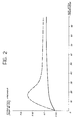
- the graph of Figure 2 shows a typical curve of the stimulation threshold value (volts, on the ordinate) as a function of time (days, on the abscissa) detected - in sheep - with an electrode according to the invention (continuous line), compared with the curve detected in identical conditions - for a conventional metal electrode (porous platinum) (broken line).
Abstract
Description
- The present invention relates to electrodes for biomedical use and has been developed with particular attention to its possible use in connection with cardiac stimulation electrodes. However, the present invention is suitable for use for the production of electrodes of any type for biomedical use, for example, for electrocardiographic or electroencephalographic use, etc.
- In this field of use, and particularly with regard to cardiac stimulation, the use of metal electrodes based on, for example, porous platinum or smooth platinum-iridium has for some time been confirmed as the preferred selection.
- The use of electrodes of this type achieves excellent results in terms of stimulation impedance (which is typically of the order of about 500 ohms for electrode surfaces of the order of 6-8 mm2) and also with regard to the stimulation-threshold characteristics.
- In this connection, it is well known that, in the days immediately following implantation in the wearer's body, the stimulation threshold (in practice the level of voltage which has to be applied to the electrode to achieve effective stimulation) increases until it reaches a peak value and then falls gradually in the following days to an asymptotic value (the so-called "chronic threshold") which is maintained during the normal use of the electrode. The stimulation-threshold value, particularly the chronic threshold value, is clearly related to the energy absorption during the performance of the stimulation function; a lower threshold value corresponds to a lower energy absorption and hence to a longer life of the supply sources (batteries) of the stimulation device.
- To prevent these phenomena from arising and/or in any case to reduce their incidence, so-called steroid eluting electrodes have recently been introduced. In this solution, the electrode, as implanted, brings with it a certain quantity of steroid agents (typically corticosteroids) which can oppose local inflammatory phenomena considered to be amongst the main factors responsible for the initial rise in the stimulation threshold. It has also been found that these electrodes have a lower chronic threshold.
- The object of the present invention is to provide an electrode for biomedical use and particularly, but not exclusively, for cardiac stimulation, which combines excellent characteristics, for example, in terms of stimulation impedance and implantation compatibility, with a uniform stimulation-threshold curve, which does not have the initial peak characteristic of conventional metal electrodes and which also shows a lower chronic threshold value.
- According to the present invention, this object is achieved by virtue of an electrode having the specific characteristics recited in the following claims.
- Essentially, the present invention is based upon the solution of coating the electrode for biomedical use with a layer of carbon material, preferably applied by cathode sputtering.
- Carbon coatings of this type are used widely in the biomedical field as shown by the documents EP-A-0 102 328, EP-A-0 224 080 and EP-A-0 291 476, amongst others.
- In all of these prior documents, the use of a carbon coating is connected essentially with the intention of conferring good biocompatibility (haemocompatibility) characteristics on the substrate (which is usually constituted by an implant such as a heart-valve prosthesis, a vascular prosthesis and/or components of these prostheses).
- The present invention is based upon the recognition of the wholly unexpected fact that, if a coating of this type is applied to an electrode, particularly a metal electrode such as a porous Pt or a smooth Pt-It electrode, it affects its performance, particularly with regard to the reduction and the elimination of the undesired initial increase in the stimulation threshold.
- Although the physical/chemical mechanism upon which this behaviour is based is not entirely clear, the Applicant has found that it is reproduced in wholly deterministic terms and is not linked to any uncertain and/or imponderable parameter. Moreover, with regard to the electrical characteristics such as the stimulation impedance, the use of a coating of carbon material enables stimulation impedance values of the order of 1000-1200 ohms to be achieved with electrode surface values of the order of 2-2.5 mm2. Naturally this is combined with the well-known biocompatible nature of carbon coating materials so that the coating can also be extended beyond the actual electrode to the adjacent parts and virtually to the entire catheter of which the electrode forms part. This also applies in particular to the parts made of non-metallic materials such as silicone and other plastics materials, with the further advantage of conferring a certain degree of lubrication on the surfaces of these parts, which facilitates their insertion by catheterization.
- With specific regard to the electrode, explicit reference will be made in the following description to a layer of carbon material applied by sputtering techniques such as those described in the three prior documents cited in the introductory part of the description. It should, however, be noted that - as is well known to experts in the art - generally similar carbon coatings can also be applied by different techniques such as, for example, high-temperature pyrolysis of a hydrocarbon, which technique is currently used for the production of pyrolytic carbon (also known commercially as LTI carbon) or low-temperature coating techniques such as the catalytic decomposition of a gaseous carbon precursor (used for the decomposition of materials known commercially as "ULTI carbons") or similar techniques about which there is extensive literature also in the patent field.
- The invention will now be described, purely by way of non-limiting example, with reference to the appended drawings, in which:
- Figure 1 shows schematically an electrode for biomedical use formed according to the present invention, and
- Figure 2 is a graph showing some operating characteristics of an electrode according to the invention.
- In the drawings, an electrode for biomedical use, generally indicated 1, is shown - purely by way of example - in the form of a cardiac stimulation electrode.
- As can readily be appreciated by a person skilled in the art, the drawings, and, in particular, Figure 1, show essentially the distal end of the electrode, the rest of the electrode (and in particular, its proximal portion) being of a structure well known in the art which does not need to be described in detail herein and, moreover, is not relevant for the purposes of an understanding of the invention.
- Within the electrode 1 it is possible, in general, to distinguish a distal end 2 on the tip of which there is a stimulation tip 3 (or actual electrode) made of an electrically-conductive material, for example, a metal such as porous Pt or smooth Pt-Ir.
- For clarity, it should be pointed out that, although the term "electrode" is correctly applied to the tip indicated 3, in normal usage, the term is also used to indicate the assembly indicated by the reference numeral 1 and the further elements normally associated therewith, that is, the device currently known as an electro-catheter.
- In accordance with widely-known criteria, the end 2 on which the electrode 3 is mounted is constituted by a tubular body with radial dimensions slightly larger than the shaft 4 of the catheter which is used to insert the electrode 3 in the stimulation position.
- The wire or wires which carry the electrical-stimulation energy to the electrode 3 extend within the shaft 4 and the end 2. One or more appendages 5, usually formed integrally with the end 2, extend like the arms of an anchor from the body of the end 2, which is usually made of a biocompatible plastics material (for example, silicone rubber), and are intended to cooperate in the manner of an anchor with the tissue of the region of the body in which the electrode 3 is implanted in order to hold the electrode 3 in place.
- A further electrode having a generally collar-like shape and indicated 7 is applied to the shaft 4 a certain distance from the end 2 for cooperating with the electrode 3 in the stimulation operation, particularly for detecting the propagation of the stimulation pulse in the heart muscle.
- In this connection, it should again be mentioned that although the present description refers specifically to a cardiac stimulation electrode, the solution according to the invention is not limited absolutely to this use or to the geometry just described or, in particular, to the simultaneous presence of two or more electrodes such as the electrodes 3 and 7 described above.
- The structure which has just been described with reference to Figure 1 is known in the art and does not require further description of specific constructional details which, moreover, are not relevant or important for the purposes of an understanding of the implementation of the invention.
- The main characteristic of the invention is that a coating 8 of carbon material such as, for example, turbostratic carbon is applied to at least a portion of the electrode 3 (and/or of the electrode 7), the coating preferably extending over the entire exposed surfaces of the electrodes 3 and 7 and also over all or part of the surfaces both of the enlarged end 2 and of the shaft 4 of the catheter for the insertion of the electrode, particularly over the appendages 5.
- Since, as is known and as will be described further below, this coating has characteristics of electrical conductivity, the coating 8 is generally interrupted adjacent the electrode 3 and/or the electrode 7, for example, by annular portions 9 of untreated silicone rubber, in order to insulate the electrode 3 and/or the electrode 7 from adjacent coated portions.
- The coating 8 is preferably constituted by a coating of carbon material formed according to the teachings given in any one of the European patent applications cited in the introductory part of the present description.
- Naturally - as already stated - the coating 8 may also be applied by other known techniques. The solution described in applications EP-A-0 102 328, EP-A-0 224,080 and EP-A-0 291 476, however, has been found particularly advantageous from various points of view, particularly with regard to the fact that the coating 8 can be applied both to metallic materials, and hence to materials with high melting points (for example, porous Pt or Pt-Ir), and to plastics materials with low softening points such as the silicone rubber which coats the end 2 and/or the shaft 4.
- Moreover, the solution described in the European patent applications cited has been found advantageous as regards the intimate adherence of the coating to whatever substrate is used, particularly when it has characteristics of flexibility. Moreover, this solution has the advantage of enabling the deposition parameters and the final characteristics of the carbon coating 8 to be regulated precisely, particularly with regard to the production of a coating having the following characteristics:
- a turbostratic structure,
- crystal dimensions less than about 100 Angstroms,
- thickness of between about 0.3 and about 1.0 microns,
- electrical resistivity of less than about 1 ohm*cm.
- adhesion to the substrate greater than 70 MPa (measured by the "pull test") and greater than 6N/cm (measured by the "tape test").
- Tests carried out by the Applicant show that the parameters given above should be considered, on the one hand, broadly preferable but, on the other hand, not absolutely essential.
- This applies in particular with regard to the parameters such as the thickness of the coating and the dimensions of the crystallites.
- The graph of Figure 2 shows a typical curve of the stimulation threshold value (volts, on the ordinate) as a function of time (days, on the abscissa) detected - in sheep - with an electrode according to the invention (continuous line), compared with the curve detected in identical conditions - for a conventional metal electrode (porous platinum) (broken line).
- Naturally, the principle of the invention remaining the same, the details of construction and forms of embodiment may be varied widely with respect to those described and illustrated, without thereby departing from the scope of the present invention.
Claims (12)
- An electrode (3, 7) for biomedical use, characterized in that it has a coating (8) of carbon material on at least a portion of its surface.
- An electrode according to Claim 1, characterized in that the carbon material has a turbostatic structure.
- An electrode according to Claim 1 or Claim 2, characterized in that the carbon material has crystallites with dimensions of less than 100 Angstroms.
- An electrode according to any one of Claims 1 to 3, characterized in that the coating (8) has a thickness of between about 0.3 and 1 microns.
- An electrode according to any one of the preceding claims, characterized in that the carbon material has an electrical resistivity of less than about 1 ohm*cm.
- An electrode according to any one of the preceding claims, characterized in that the adhesion of the coating to the said portion is greater than 70 MPa and greater than 6N/cm, measured by the "pull test" and by the "tape test", respectively.
- An electrode according to any one of the preceding claims, characterized in that the coating (8) is applied by cathode sputtering.
- An electrode according to any one of the preceding claims, characterized in that the said portion of the surface is made of metallic material.
- An electrode according to Claim 8, characterized in that the metallic material is selected from the group constituted by porous Pt and smooth Pt-Ir.
- An electrode according to any one of the preceding claims, characterized in that it has associated support means (4) of electrically non-conductive material, and in that the coating of carbon material (8) is also applied to at least a portion of the support means (4).
- An electrode according to Claim 10, characterized in that the support means (4) jointly define a catheter for inserting the electrode (3) in position.
- An electrode according to Claim 11, characterized in that a further electrode (7) is mounted on the insertion catheter, and in that at least part of the further electrode is also provided with a surface coating of the carbon material (8).
Applications Claiming Priority (2)
| Application Number | Priority Date | Filing Date | Title |
|---|---|---|---|
| ITTO960519 | 1996-06-17 | ||
| IT96TO000519A IT1286102B1 (en) | 1996-06-17 | 1996-06-17 | ELECTRODE FOR BIOMEDICAL USE, FOR EXAMPLE FOR CARDIOSTIMULATION |
Publications (3)
| Publication Number | Publication Date |
|---|---|
| EP0813885A2 true EP0813885A2 (en) | 1997-12-29 |
| EP0813885A3 EP0813885A3 (en) | 1999-10-20 |
| EP0813885B1 EP0813885B1 (en) | 2005-05-25 |
Family
ID=11414720
Family Applications (1)
| Application Number | Title | Priority Date | Filing Date |
|---|---|---|---|
| EP97109537A Expired - Lifetime EP0813885B1 (en) | 1996-06-17 | 1997-06-12 | An electrode for biomedical use, for example, for cardiac stimulation |
Country Status (4)
| Country | Link |
|---|---|
| EP (1) | EP0813885B1 (en) |
| AT (1) | ATE296143T1 (en) |
| DE (1) | DE69733332T2 (en) |
| IT (1) | IT1286102B1 (en) |
Cited By (4)
| Publication number | Priority date | Publication date | Assignee | Title |
|---|---|---|---|---|
| WO2001003767A1 (en) * | 1999-07-13 | 2001-01-18 | Cardiac Pacemakers, Inc. | Ring electrode with porous member |
| US8017179B2 (en) | 2003-12-16 | 2011-09-13 | Cardiac Pacemakers, Inc. | Coatings for implantable electrodes |
| WO2017062405A1 (en) * | 2015-10-06 | 2017-04-13 | Cardiac Pacemakers, Inc. | Fixation device for a subcutaneous electrode |
| US9775992B2 (en) | 2015-02-13 | 2017-10-03 | Cardiac Pacemakers, Inc. | Implantable electrode |
Citations (5)
| Publication number | Priority date | Publication date | Assignee | Title |
|---|---|---|---|---|
| US4542752A (en) * | 1983-04-22 | 1985-09-24 | Cordis Corporation | Implantable device having porous surface with carbon coating |
| US4612100A (en) * | 1983-12-20 | 1986-09-16 | Siemens Aktiengesellschaft | Method for the fabrication of an implantable electrode |
| EP0224080A2 (en) * | 1985-11-26 | 1987-06-03 | SORIN BIOMEDICA S.p.A. | Improvements in and relating to the manufacture of prosthetic devices |
| EP0291476A2 (en) * | 1987-05-11 | 1988-11-17 | SORIN BIOMEDICA S.p.A. | Device for contacting blood flows |
| US4934381A (en) * | 1975-05-09 | 1990-06-19 | Macgregor David C | Porous carbon pacemaker electrode |
-
1996
- 1996-06-17 IT IT96TO000519A patent/IT1286102B1/en active IP Right Grant
-
1997
- 1997-06-12 AT AT97109537T patent/ATE296143T1/en not_active IP Right Cessation
- 1997-06-12 DE DE69733332T patent/DE69733332T2/en not_active Expired - Lifetime
- 1997-06-12 EP EP97109537A patent/EP0813885B1/en not_active Expired - Lifetime
Patent Citations (5)
| Publication number | Priority date | Publication date | Assignee | Title |
|---|---|---|---|---|
| US4934381A (en) * | 1975-05-09 | 1990-06-19 | Macgregor David C | Porous carbon pacemaker electrode |
| US4542752A (en) * | 1983-04-22 | 1985-09-24 | Cordis Corporation | Implantable device having porous surface with carbon coating |
| US4612100A (en) * | 1983-12-20 | 1986-09-16 | Siemens Aktiengesellschaft | Method for the fabrication of an implantable electrode |
| EP0224080A2 (en) * | 1985-11-26 | 1987-06-03 | SORIN BIOMEDICA S.p.A. | Improvements in and relating to the manufacture of prosthetic devices |
| EP0291476A2 (en) * | 1987-05-11 | 1988-11-17 | SORIN BIOMEDICA S.p.A. | Device for contacting blood flows |
Non-Patent Citations (1)
| Title |
|---|
| GUPTA B K ET AL: "MICROMECHANICAL PROPERTIES OF AMORPHOUS CARBON COATINGS DEPOSITED BY DIFFERENT DEPOSITION TECHNIQUES" THIN SOLID FILMS, vol. 270, no. 1/02, 1 December 1995 (1995-12-01), pages 391-398, XP000595248 ISSN: 0040-6090 * |
Cited By (11)
| Publication number | Priority date | Publication date | Assignee | Title |
|---|---|---|---|---|
| WO2001003767A1 (en) * | 1999-07-13 | 2001-01-18 | Cardiac Pacemakers, Inc. | Ring electrode with porous member |
| US6263250B1 (en) | 1999-07-13 | 2001-07-17 | Cardiac Pacemakers, Inc. | Ring electrode with porous member |
| US6516232B2 (en) | 1999-07-13 | 2003-02-04 | Cardiac Pacemakers, Inc. | Ring electrode with porous member |
| US8017179B2 (en) | 2003-12-16 | 2011-09-13 | Cardiac Pacemakers, Inc. | Coatings for implantable electrodes |
| US8017178B2 (en) | 2003-12-16 | 2011-09-13 | Cardiac Pacemakers, Inc. | Coatings for implantable electrodes |
| US9775992B2 (en) | 2015-02-13 | 2017-10-03 | Cardiac Pacemakers, Inc. | Implantable electrode |
| WO2017062405A1 (en) * | 2015-10-06 | 2017-04-13 | Cardiac Pacemakers, Inc. | Fixation device for a subcutaneous electrode |
| JP2018529448A (en) * | 2015-10-06 | 2018-10-11 | カーディアック ペースメイカーズ, インコーポレイテッド | Subcutaneous electrode fixation device |
| US10226618B2 (en) | 2015-10-06 | 2019-03-12 | Cardiac Pacemakers, Inc. | Fixation device for a subcutaneous electrode |
| AU2016333862B2 (en) * | 2015-10-06 | 2019-05-16 | Cardiac Pacemakers, Inc. | Fixation device for a subcutaneous electrode |
| US11253696B2 (en) | 2015-10-06 | 2022-02-22 | Cardiac Pacemakers, Inc. | Fixation device for a subcutaneous electrode |
Also Published As
| Publication number | Publication date |
|---|---|
| ATE296143T1 (en) | 2005-06-15 |
| DE69733332D1 (en) | 2005-06-30 |
| EP0813885A3 (en) | 1999-10-20 |
| EP0813885B1 (en) | 2005-05-25 |
| ITTO960519A0 (en) | 1996-06-17 |
| IT1286102B1 (en) | 1998-07-07 |
| DE69733332T2 (en) | 2005-10-20 |
| ITTO960519A1 (en) | 1997-12-17 |
Similar Documents
| Publication | Publication Date | Title |
|---|---|---|
| US5411544A (en) | Defibrillation lead with improved mechanical and electrical characteristics | |
| US7013182B1 (en) | Conductive polymer sheath on defibrillator shocking coils | |
| US4033357A (en) | Non-fibrosing cardiac electrode | |
| US6501994B1 (en) | High impedance electrode tip | |
| AU637353B2 (en) | Patch electrodes for use with defibrillators | |
| US5609622A (en) | Implantable electrode with conductive polytetrafluoroethylene elecrode | |
| US4444206A (en) | Mesh tip pacing lead assembly | |
| US4628944A (en) | Cardiac pacing lead with biodegradable fixation structure | |
| EP0573275B1 (en) | High efficiency tissue stimulating and signal sensing electrode | |
| US5133365A (en) | Implantable tapered spiral endocardial lead for use in internal defibrillation | |
| WO1997007851A1 (en) | Medical electrical lead having temporarily rigid fixation | |
| US4919135A (en) | Triaxial electrode | |
| WO1994000186A1 (en) | A patch electrode | |
| WO2008140376A1 (en) | Tantalum electrode | |
| WO1992020401A1 (en) | Defibrillator and demand pacer catheter and method | |
| WO1998031419A1 (en) | Electrode for high impedance heart stimulation | |
| EP0085967B1 (en) | Cardiac pacing lead with biodegradable fixation means | |
| Stokes | Implantable pacing lead technology | |
| EP0813885B1 (en) | An electrode for biomedical use, for example, for cardiac stimulation | |
| CA1063680A (en) | Non-fibrosing cardiac electrode | |
| EP0064289B2 (en) | Body implantable lead | |
| Irnich | Comparison of pacing electrodes of different shape and material—recommendations | |
| Mugica et al. | Clinical Experience with 910 Carbon Tip Leads: Comparison with Polished Platinum Leads: Expérience Clinique avec 910 Électrodes au Carbone, Comparaison avec les Électrodes en Platine Poli | |
| EP0237316B1 (en) | Cardiac pacing device | |
| Mugica et al. | Clinical experience with new leads |
Legal Events
| Date | Code | Title | Description |
|---|---|---|---|
| PUAI | Public reference made under article 153(3) epc to a published international application that has entered the european phase |
Free format text: ORIGINAL CODE: 0009012 |
|
| AK | Designated contracting states |
Kind code of ref document: A2 Designated state(s): AT BE CH DE ES FR GB GR IT LI NL PT SE |
|
| AX | Request for extension of the european patent |
Free format text: AL;LT;LV;RO;SI |
|
| PUAL | Search report despatched |
Free format text: ORIGINAL CODE: 0009013 |
|
| AK | Designated contracting states |
Kind code of ref document: A3 Designated state(s): AT BE CH DE DK ES FI FR GB GR IE IT LI LU MC NL PT SE |
|
| AX | Request for extension of the european patent |
Free format text: AL;LT;LV;RO;SI |
|
| 17P | Request for examination filed |
Effective date: 20000316 |
|
| AKX | Designation fees paid |
Free format text: AT BE CH DE ES FR GB GR IT LI NL PT SE |
|
| RAP1 | Party data changed (applicant data changed or rights of an application transferred) |
Owner name: SORIN BIOMEDICA CRM S.R.L. |
|
| GRAP | Despatch of communication of intention to grant a patent |
Free format text: ORIGINAL CODE: EPIDOSNIGR1 |
|
| GRAS | Grant fee paid |
Free format text: ORIGINAL CODE: EPIDOSNIGR3 |
|
| GRAA | (expected) grant |
Free format text: ORIGINAL CODE: 0009210 |
|
| AK | Designated contracting states |
Kind code of ref document: B1 Designated state(s): AT BE CH DE ES FR GB GR IT LI NL PT SE |
|
| PG25 | Lapsed in a contracting state [announced via postgrant information from national office to epo] |
Ref country code: NL Free format text: LAPSE BECAUSE OF FAILURE TO SUBMIT A TRANSLATION OF THE DESCRIPTION OR TO PAY THE FEE WITHIN THE PRESCRIBED TIME-LIMIT Effective date: 20050525 Ref country code: LI Free format text: LAPSE BECAUSE OF FAILURE TO SUBMIT A TRANSLATION OF THE DESCRIPTION OR TO PAY THE FEE WITHIN THE PRESCRIBED TIME-LIMIT Effective date: 20050525 Ref country code: CH Free format text: LAPSE BECAUSE OF FAILURE TO SUBMIT A TRANSLATION OF THE DESCRIPTION OR TO PAY THE FEE WITHIN THE PRESCRIBED TIME-LIMIT Effective date: 20050525 Ref country code: BE Free format text: LAPSE BECAUSE OF FAILURE TO SUBMIT A TRANSLATION OF THE DESCRIPTION OR TO PAY THE FEE WITHIN THE PRESCRIBED TIME-LIMIT Effective date: 20050525 Ref country code: AT Free format text: LAPSE BECAUSE OF FAILURE TO SUBMIT A TRANSLATION OF THE DESCRIPTION OR TO PAY THE FEE WITHIN THE PRESCRIBED TIME-LIMIT Effective date: 20050525 |
|
| REG | Reference to a national code |
Ref country code: GB Ref legal event code: FG4D |
|
| REG | Reference to a national code |
Ref country code: CH Ref legal event code: EP |
|
| REF | Corresponds to: |
Ref document number: 69733332 Country of ref document: DE Date of ref document: 20050630 Kind code of ref document: P |
|
| PG25 | Lapsed in a contracting state [announced via postgrant information from national office to epo] |
Ref country code: SE Free format text: LAPSE BECAUSE OF FAILURE TO SUBMIT A TRANSLATION OF THE DESCRIPTION OR TO PAY THE FEE WITHIN THE PRESCRIBED TIME-LIMIT Effective date: 20050825 Ref country code: GR Free format text: LAPSE BECAUSE OF FAILURE TO SUBMIT A TRANSLATION OF THE DESCRIPTION OR TO PAY THE FEE WITHIN THE PRESCRIBED TIME-LIMIT Effective date: 20050825 |
|
| PG25 | Lapsed in a contracting state [announced via postgrant information from national office to epo] |
Ref country code: ES Free format text: LAPSE BECAUSE OF FAILURE TO SUBMIT A TRANSLATION OF THE DESCRIPTION OR TO PAY THE FEE WITHIN THE PRESCRIBED TIME-LIMIT Effective date: 20050905 |
|
| PG25 | Lapsed in a contracting state [announced via postgrant information from national office to epo] |
Ref country code: PT Free format text: LAPSE BECAUSE OF FAILURE TO SUBMIT A TRANSLATION OF THE DESCRIPTION OR TO PAY THE FEE WITHIN THE PRESCRIBED TIME-LIMIT Effective date: 20051027 |
|
| REG | Reference to a national code |
Ref country code: CH Ref legal event code: PL |
|
| NLV1 | Nl: lapsed or annulled due to failure to fulfill the requirements of art. 29p and 29m of the patents act | ||
| ET | Fr: translation filed | ||
| PLBE | No opposition filed within time limit |
Free format text: ORIGINAL CODE: 0009261 |
|
| STAA | Information on the status of an ep patent application or granted ep patent |
Free format text: STATUS: NO OPPOSITION FILED WITHIN TIME LIMIT |
|
| 26N | No opposition filed |
Effective date: 20060228 |
|
| PGFP | Annual fee paid to national office [announced via postgrant information from national office to epo] |
Ref country code: GB Payment date: 20120606 Year of fee payment: 16 Ref country code: FR Payment date: 20120619 Year of fee payment: 16 |
|
| PGFP | Annual fee paid to national office [announced via postgrant information from national office to epo] |
Ref country code: IT Payment date: 20120613 Year of fee payment: 16 |
|
| PGFP | Annual fee paid to national office [announced via postgrant information from national office to epo] |
Ref country code: DE Payment date: 20130605 Year of fee payment: 17 |
|
| GBPC | Gb: european patent ceased through non-payment of renewal fee |
Effective date: 20130612 |
|
| REG | Reference to a national code |
Ref country code: FR Ref legal event code: ST Effective date: 20140228 |
|
| PG25 | Lapsed in a contracting state [announced via postgrant information from national office to epo] |
Ref country code: GB Free format text: LAPSE BECAUSE OF NON-PAYMENT OF DUE FEES Effective date: 20130612 |
|
| PG25 | Lapsed in a contracting state [announced via postgrant information from national office to epo] |
Ref country code: IT Free format text: LAPSE BECAUSE OF NON-PAYMENT OF DUE FEES Effective date: 20130612 Ref country code: FR Free format text: LAPSE BECAUSE OF NON-PAYMENT OF DUE FEES Effective date: 20130701 |
|
| REG | Reference to a national code |
Ref country code: DE Ref legal event code: R119 Ref document number: 69733332 Country of ref document: DE |
|
| REG | Reference to a national code |
Ref country code: DE Ref legal event code: R119 Ref document number: 69733332 Country of ref document: DE Effective date: 20150101 |
|
| PG25 | Lapsed in a contracting state [announced via postgrant information from national office to epo] |
Ref country code: DE Free format text: LAPSE BECAUSE OF NON-PAYMENT OF DUE FEES Effective date: 20150101 |