EP0816122A2 - Transfer decorated members and the method of manufacturing the same - Google Patents
Transfer decorated members and the method of manufacturing the same Download PDFInfo
- Publication number
- EP0816122A2 EP0816122A2 EP97108801A EP97108801A EP0816122A2 EP 0816122 A2 EP0816122 A2 EP 0816122A2 EP 97108801 A EP97108801 A EP 97108801A EP 97108801 A EP97108801 A EP 97108801A EP 0816122 A2 EP0816122 A2 EP 0816122A2
- Authority
- EP
- European Patent Office
- Prior art keywords
- transfer
- substrate
- decorated
- manufacturing
- sheets
- Prior art date
- Legal status (The legal status is an assumption and is not a legal conclusion. Google has not performed a legal analysis and makes no representation as to the accuracy of the status listed.)
- Granted
Links
Images


Classifications
-
- B—PERFORMING OPERATIONS; TRANSPORTING
- B44—DECORATIVE ARTS
- B44C—PRODUCING DECORATIVE EFFECTS; MOSAICS; TARSIA WORK; PAPERHANGING
- B44C5/00—Processes for producing special ornamental bodies
- B44C5/04—Ornamental plaques, e.g. decorative panels, decorative veneers
- B44C5/043—Ornamental plaques, e.g. decorative panels, decorative veneers containing wooden elements
-
- B—PERFORMING OPERATIONS; TRANSPORTING
- B44—DECORATIVE ARTS
- B44C—PRODUCING DECORATIVE EFFECTS; MOSAICS; TARSIA WORK; PAPERHANGING
- B44C1/00—Processes, not specifically provided for elsewhere, for producing decorative surface effects
- B44C1/16—Processes, not specifically provided for elsewhere, for producing decorative surface effects for applying transfer pictures or the like
- B44C1/165—Processes, not specifically provided for elsewhere, for producing decorative surface effects for applying transfer pictures or the like for decalcomanias; sheet material therefor
- B44C1/17—Dry transfer
-
- B—PERFORMING OPERATIONS; TRANSPORTING
- B29—WORKING OF PLASTICS; WORKING OF SUBSTANCES IN A PLASTIC STATE IN GENERAL
- B29C—SHAPING OR JOINING OF PLASTICS; SHAPING OF MATERIAL IN A PLASTIC STATE, NOT OTHERWISE PROVIDED FOR; AFTER-TREATMENT OF THE SHAPED PRODUCTS, e.g. REPAIRING
- B29C2791/00—Shaping characteristics in general
- B29C2791/004—Shaping under special conditions
- B29C2791/006—Using vacuum
-
- B—PERFORMING OPERATIONS; TRANSPORTING
- B29—WORKING OF PLASTICS; WORKING OF SUBSTANCES IN A PLASTIC STATE IN GENERAL
- B29C—SHAPING OR JOINING OF PLASTICS; SHAPING OF MATERIAL IN A PLASTIC STATE, NOT OTHERWISE PROVIDED FOR; AFTER-TREATMENT OF THE SHAPED PRODUCTS, e.g. REPAIRING
- B29C51/00—Shaping by thermoforming, i.e. shaping sheets or sheet like preforms after heating, e.g. shaping sheets in matched moulds or by deep-drawing; Apparatus therefor
- B29C51/10—Forming by pressure difference, e.g. vacuum
Definitions
- the present invention relates to transfer decorated members and a method of manufacturing the same, and more specifically to transfer decorated members used for various building components such as fittings, furniture, housings of various devices, etc. and methods of manufacturing the same.
- large-sized flat members for example, door members such as room doors, kitchen doors and doors of built-in storage units, wall members and side members of built-in furniture, have so-called framed panel structures in order to keep high strength, reduce weight and achieve good designs (beauty).
- framed panel structure frame members such as stiles and rails are assembled to form a frame, and panels are set in said frame.
- the decorated members are manufactured using decorated frame members and panels which are made of ligneous substrates such as plywoods, laminated lumbers, particle boards or medium density fiber boards (MDF) and which are separately decorated by appropriate methods such as the following:
- the above-mentioned method i.e., the separate decorating method
- various kinds of decorated members can easily be obtained in a small amount for each kind, by using decorative sheets or transfer sheets with a relatively small kinds of decorative patterns.
- the following methods can be preferably used to produce various kinds of decorated members in a small amount for each kind: 1) varying the combinations of decorative patterns of frame members and those of panels, 2) varying the shapes of the frame members and panels, and 3) varying the angles of decorative patterns on decorative sheets or transfer sheets and combining them.
- the decorated members are manufactured by combining the frame members and panels which have been decorated separately, and thus the beauty of the framed panel structure is obtained.
- the overall decorating method is classified into two methods: a flat plate method in which a decorative pattern of a framed panel structure is provided onto a substrate with a flat surface; and a three-dimensional method in which a decorative pattern of a framed panel structure is provided onto a substrate with a three-dimensional surface shape similar to the surface shape of a real framed panel structure.
- the three-dimensional method is an overall decorating method in which a thermoformable decorative sheet or transfer sheet is laminated or transferred on a substrate having a three-dimensional surface shape by means of a vacuum forming process, thereby providing a decorative pattern.
- the three-dimensional method has an advantage in that not only a decorative pattern of a framed panel structure is obtained, but also a three-dimensional design similar to the structure of the real framed panel is obtained.
- the overall decorating method however, a large-sized decorative sheet or transfer sheet is inevitably required when a large-sized decorated member is to be manufactured.
- the overall decorating method requires a large-scale printing machine for the preparation of a large-sized decorative sheet or transfer sheet.
- the size of the decorated members is limited by the effective printing area of the printing machine used to print the decorative sheet/transfer sheet.
- the decorative sheet or transfer sheet with the decorative pattern of framed panel structure needs to be printed and produced.
- thermoformable decorative sheet or transfer sheet may deform due to the tension or the heat of the dryer in the printing process, resulting in the distortion of the decorative pattern of framed panel structure. Consequently, mismatching occurs between the decorative pattern and the shape of the substrate, and the design of the decorated members is degraded.
- the problem of distortion of decorative pattern can be solved by the use of a heat-resistant film which is resistant to thermal deformation.
- a heat-resistant film which is resistant to thermal deformation.
- lamination or transfer by means of vacuum forming process is impossible.
- the heat-resistant film cannot be used to provide a decorative pattern onto the substrate having a surface with a three-dimensional shape.
- the separate decorating method has the problems in that the process control is difficult and the productivity of decorated members is low due to the complicated manufacturing process, and the manufacturing cost cannot be reduced.
- the overall decorating method is advantageous in solving the problems of the separate decorating method, the size of the decorated members is limited and the manufacture of various kinds of decorated members in a small amount for each kind is difficult. Moreover, it is difficult to provide a decorative pattern onto the substrate so as to match with the three-dimensional surface shape of the substrate.
- An object of the present invention is to provide transfer decorated members and a method of manufacturing the same, wherein the transfer decorated members have an excellent design consisting of a combination of plural different patterns, like a framed panel structure, and the transfer decorated members can easily be manufactured with high productivity.
- the present invention aims at providing transfer decorated members and a method of manufacturing the same, wherein the size of the decorated members is not limited by the effective area of the printing machine, various kinds of decorated members can easily be manufactured in a small amount for each kind, and the decorative pattern can easily be provided on the substrate with a three-dimensional surface shape in correspondence with it.
- Another object of the present invention is to provide transfer decorated members and a method of manufacturing the same, wherein the process controllability and the productivity of products can be improved by simplified manufacturing process, and accordingly the manufacturing cost can be reduced.
- this invention provides transfer decorated members characterized in that a transfer layer (2) for decoration is provided on at least one region of the surface of the substrate by means of transfer process.
- This invention also provides a method of manufacturing transfer decorated members, characterized by comprising the steps of:
- the surface of the substrate (1) may have a three-dimensional shape.
- the term "at least one region of the surface of the substrate” means the regions of an arbitrary number from 1 to n among the n regions, into which the surface of the substrate is divided.
- the size of the decorated members is not limited by the effective printing area of the printing machine.
- this invention provides transfer decorated members and a method of manufacturing the same with high productivity, wherein the size of the decorated members is not limited by the effective printing area of the printing machine, and various kinds of decorated members can easily be manufactured in a small amount for each kind by changing the combination of decorative patterns.
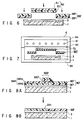
- FIG. 1 is a plan view showing the structure of the transfer decorated member according to the first embodiment of the present invention
- FIG. 2 is a cross-sectional view taken along line II-II in FIG. 1.
- the transfer decorated member includes a substrate 1 of a medium density fiberboard (MDF) molded to have a peripheral frame-like region A, a panel-like region a situated inside the frame-like region A, and a groove-like concave region C defined between the frame-like region A and the panel-like region B.
- a transfer layer 2 having a wood grain pattern is formed on the panel-like region B and concave region C of substrate 1 by means of transfer process, with an adhesive 3 interposed. Since the frame-like region A is exposed, the surface design of the substrate 1 is viewed as a pictorial pattern there.
- FIGS. 3A to 3E are cross-sectional views illustrating the process of manufacturing the transfer decorated members according to the first embodiment.
- the adhesive 3 is coated on the panel-like region B and concave region C (corresponding to the transfer pattern formation region in this embodiment) of the substrate 1 selectively by means of spraying, etc.
- a thermoformable transfer sheet 5 consisting of a thermoformable sheet 4 and a separable transfer layer 2 formed on the releasing surface of the thermoformable sheet 4 is cut in a plan shape corresponding to the transfer pattern formation region and placed on the adhesive 3 of substrate 1.
- the substrate 1 is situated within a vacuum forming machine 6, as shown in FIG. 3C.
- the housing 63, 64 is closed and the transfer sheet 5 is heated and softened by the heat of a heat source 61 such as an electric heater. Then, the pressure within the lower housing 63 partitioned in the housing by a silicone rubber film 62 is reduced, while compressed air is introduced into the upper housing 64.
- a heat source 61 such as an electric heater.
- the transfer sheet 5 is deformed by means of the silicone rubber 62 and put in close contact with the three-dimensional surface of the substrate 1 with the adhesive 3 interposed therebetween.
- the transfer layer 2 is put in close contact with the surface of substrate 1, with the adhesive 3 interposed.
- the vacuum forming machine 6 the application of vacuum pressure is stopped, and the substrate 1 is taken out of the housing. Thus, the vacuum forming process is completed.
- thermoformable sheet 4 is removed from the transfer layer 2.
- the laminated structure of the transfer decorated member, wherein the transfer layer 2 is put in close contact with the transfer pattern formation region of the substrate 1, is completed.
- the substrate 1 may be formed of, for example, a ligneous material such as plywood, laminated lumber, a particle board or an MDF, an inorganic material such as a plasterboard, a molded product of a resin or a metal, or a lamination or composite thereof, or any of the other conventional materials.
- a ligneous material such as plywood, laminated lumber, a particle board or an MDF
- an inorganic material such as a plasterboard, a molded product of a resin or a metal, or a lamination or composite thereof, or any of the other conventional materials.
- the transfer layer 2 with a desired decorative pattern is separably provided on the releasing surface of the thermoformable sheet 4.
- the thermoformable sheet 4 may be formed of, for example, a thermoformable synthetic resin such as polyvinyl chloride, polystyrene or polypropylene, or a lamination thereof, etc.
- a thermoformable synthetic resin such as polyvinyl chloride, polystyrene or polypropylene, or a lamination thereof, etc.
- the surface of the thermoformable sheet 4, on which the transfer layer 2 is to be provided may be provided with a releasing layer, a gloss control layer, etc.
- the transfer layer 2 may be formed of, for example, a conventionally known printing ink or coating agent, in which a coloring agent of an organic or inorganic dye or pigment is dispersed in an appropriate binding agent. It is desirable, however, that the transfer layer 2 have thermoformability such that the transfer layer 2 is deformed along with the thermoformable sheet 4 in accordance with the three-dimensional surface of the substrate 1 in the vacuum forming process.
- the binding agent in the transfer layer 2 may be preferably formed of, for example, acrylic resin, polyvinyl chloride resin, polyvinyl acetate resin, polyvinyl butyral resin, vinyl chloride-vinyl acetate copolymer resin, ethylene-vinyl acetate copolymer resin, polyamide resin, chlorinated polypropylene resin, urethane resin, nitrocellulose, cellulose acetate, cellulose acetate propionate, chlorinated rubber, cyclized rubber, etc.
- the transfer layer 2 can be formed by conventional methods, for example, printing methods such as gravure printing method, offset printing method, screen printing method or flexographic printing method, or coating methods such as a gravure coating method, knife coating method, roll-coating method or spray coating method.
- printing methods such as gravure printing method, offset printing method, screen printing method or flexographic printing method
- coating methods such as a gravure coating method, knife coating method, roll-coating method or spray coating method.
- the transfer layer 2 is a layer for decorating the substrate.
- the pattern to be formed as the transfer layer 2 is not limited to common wood grain patterns, and may be wooden mosaic patterns, stone grain patterns, metallic patterns, various concrete or abstract patterns, monochromatic plain patterns, or any other arbitrary pattern.
- the term "pattern” in this context is not limited to commonly accepted senses, and it may refer to monochromatic plain patterns, as mentioned above, and such semitransparent patterns as to make underlayers visible, as described below.
- the transfer layer 2 may include a layer other than the pattern layer.
- it may comprise a lamination of a releasing layer, a surface protective layer, a pattern layer and an adhesive layer which are formed successively on the thermoformable sheet 4.
- the adhesive 3 is preferably coated on the substrate 1.
- the pattern can be formed only on the transfer pattern formation region.
- the coating of the adhesive 3 on the substrate 1 is advantageous in that when the transfer sheet 5 has been cut in a size slightly greater than the transfer pattern formation region, even when a slight misplacement of the transfer sheet 5 occurs, a non-pattern area is not formed within the transfer pattern formation region.
- the adhesive 3 may be coated by conventional methods such as a brushing method, a spraying method and a roll-coating method.
- the adhesive 3 may be coated on the surface of the transfer layer 2 of transfer sheet 5, in place of the surface of the substrate 1. However, if the adhesive 3 is coated on the surface of the transfer layer 2, the transfer decorated member may become defective once misplacement of the transfer sheet 5 occurs in the transferring step. Thus, precision in alignment is required.
- the adhesive 3 may be a conventional one, for example, vinyl acetate resin emulsion adhesive, acrylic resin emulsion adhesive, urethane adhesive, epoxy adhesive, acrylic adhesive, or cellulose derivative adhesive.
- the adhesive 3 has low tackiness in a semi-hardened state or semi-dried state. In this case, when the transfer sheet 5 is placed on the substrate 1, the transfer sheet 5 can be provisionally held and the workability is enhanced.
- a solvent component in the adhesive 3 between the transfer layer 2 and substrate 1 be completely dried up and removed. It is difficult in general, however, to completely remove the solvent component in the adhesive 3. As a result, the solvent component in the adhesive 3 is confined between the substrate 1 and the transfer sheet 5 at the time of transfer. At the time of heating in the transfer step, the solvent component is vaporized and expanded. Consequently, the transfer layer 2 transferred on the substrate 1 may be swollen. The swelling phenomenon can be effectively prevented by making many fine through-holes in the transfer sheet 5 in advance and discharging the vaporized residual solvent through the through-holes.
- Such holes are also advantageous in that the air confined in the concave region C can be discharged when the transfer sheet 5 is placed onto the substrate 1 with a three-dimensional surface, and the transfer sheet 5 can be put in close contact with the inner surface of the concave region C.
- the transfer decorated members having the above structure have the following advantageous effects.
- the transfer layer 2 having a decorative pattern is transferred selectively on the transfer pattern formation region which is a part of the surface of the substrate.
- the transfer decorated members can be manufactured easily as with the conventional overall decorating method.
- the problem caused by the limited effective printing area of the printing machine is solved.
- the problem of misalignment caused by the distortion of the pattern in the printing process can be eliminated, thus the yield of the products can be enhanced.
- Even when a distortion occurs in each transfer sheet 5 in the printing step the transfer sheet 5, before placed on the substrate, is cut in a size slightly greater than the transfer pattern formation region, and the transfer layer 2 is transferred only onto the transfer pattern formation region where the adhesive 3 is selectively coated.
- the degree of distortion is within such a range that the design of the decorative pattern itself is not seriously damaged, no problem will arise.
- the transfer decorated members can be provided with a good design by the combination of the region without transfer layer, which shows the surface design of the substrate itself, and the transfer decorative pattern formation region, which shows the decorative pattern of the transfer layer.
- the transfer layer can be put in contact with the substrate 1 with a three-dimensional surface and transferred thereon by the vacuum forming process using the thermoformable transfer sheet.
- a pattern can be transferred even on the concave region of the substrate in good condition with no transfer defect.
- at least a part of the boundary of the transfer layer is provided in correspondence with the three-dimensional surface shape of the substrate.
- FIG. 4 is a pictorial view showing the structure of the transfer decorated member according to the second embodiment.
- FIG. 5A is a cross-sectional view taken along line VA-VA in FIG. 4
- FIG. 5B is a cross-sectional view taken along line VB-VB in FIG. 4.
- the structural parts common to those in FIGS. 1 and 2 are denoted by like reference numerals, and the detailed description thereof will be omitted in the description below. Only different parts will be described.
- the transfer decorated member according to the second embodiment is a modification of the first embodiment and takes advantages of both the conventional separate decorating method and overall decorating method. Specifically, as shown in FIG. 4, seven transfer layers 2 EF , 2 GHI and 2 J are individually bonded on a single substrate 1 by means of an adhesive 3.
- the transfer decorated member has a pattern of a framed panel structure for a door.
- the substrate 1 is a laminated lumber with a longitudinal grain.
- Two rectangular frame-like concave regions D are arranged longitudinally.
- the concave regions D define the surface of the substrate 1 in an 8-shaped pattern comprising stile-like regions E and F, rail-like regions G, H and I, and panel-like regions J.
- the transfer layers 2 EF with such a degree of transparency as to make the underlayer visible are bonded to the stile-like regions E and F.
- the surface design of the substrate 1 is visible in the stile-like regions E and F.
- the transfer layers 2 GHI with transverse grain patterns are bonded to the rail-like regions G, H and I.
- the transfer layers 2 J with annual-ring patterns are bonded to the panel-like regions J.
- the transfer layers 2 GHI of the rail-like regions G to I are continuously bonded to those of the concave regions D, which adjoin the rail-like regions G to I.
- the transfer layers 2 EF of the stile-like regions E and F are continuously bonded to those of the concave regions D, which adjoin the stile-like regions E and F.
- the transfer decorated member having the above structure has, in addition to the advantageous effects of the first embodiment, the following advantageous effects.
- the overlapped portion of the upper transfer layer 2e EF is removed along with the lower thermoformable sheet 4 GHI , as shown in FIG. 8B, when the lower thermoformable sheet 4 GHI is removed.
- the transfer layers 2 GHI and 2 EF are not doubly transferred, and an unbeautiful dense-color area or step in height is not formed.
- the transfer sheets 5 EF , 5 GHI and 5 J are intentionally made to overlap each other, formation of a gap due to non-transfer in boundary areas of the transfer pattern formation regions can be prevented.
- the manufacturing method of this invention is more reliable than the decorating method by means of lamination of decorative sheets.
- the decorating method by means of lamination of decorative sheets it is very difficult to exactly cut the decorative sheets in sizes corresponding to large pattern regions, to exactly abut the cut decorative sheets upon each other without gap or overlap, and to adhere them to the substrate.
- the decorating method by means of lamination of decorative sheets tends to cause defects of pattern, to degrade the design of the pattern, and to form stepped overlap which may cause the peeling of the decorative sheets.
- the reliability of this method is low.
- various kinds of transfer decorated members can be manufactured by preparing a relatively small number of kinds of transfer sheets 5 EF , 5 GHI and 5 J and combining the substrate 1 with the transfer sheets 5 EF , 5 GHI and 5 J .
- various kinds of products can be easily manufactured with a small number for each kind.
- this embodiment has an advantage in that the size of the manufacturable transfer decorated members is not limited by the effective printing area of the printing machine. This advantage will now be described supplementarily.
- the transfer sheets 5 EF for decorating the stile-like regions E and F which are the longest pattern regions, be produced by means of a printing machine having an effective printing area greater than the length of the stile-like regions E, F.
- the transfer sheets 5 EF for the longest stile-like regions E and F can be printed by means of a printing machine having an effective printing area shorter than the length of the stile-like regions E, F, for example, by providing the transfer sheets 5 EF with endless patterns consisting of a repetition unit shorter than the length of the stile-like regions E, F.
- This method of obtaining the transfer decorated member having a size greater than the effective printing area of the printing machine by using the transfer sheets with endless patterns can also be applied to the first embodiment.
- the transfer decorated members according to the present invention include a transfer decorated member wherein a transparent or semitransparent protective layer is coated on the surface after the transfer layer 2 has been transferred on the transfer pattern formation region (panel-like region B and concave region C in the first embodiment, and whole surface in the second embodiment).
- the protective layer provides the surface of the transfer decorated member with surface properties such as wear resistance, water resistance, solvent resistance, contamination resistance or weather resistance.
- the protective layer may be formed on only the transfer pattern formation region or on the entire surface including the region without transfer layer (the frame-like region A in the first embodiment).
- the coating material forming the protective layer may be any of the conventional coating agents or top-coating agents such as acrylic coating agents, urethane coating agents, polyester coating agents, cellulose derivative coating agents, or fluorocarbon coating agents.
- the protection layer may be formed by the use of the transfer sheet 5.
- the transfer sheet 5 which is placed last among all the transfer sheets 5, may not necessarily be cut in a size of the corresponding transfer pattern formation region.
- a transfer decorated member wherein the entire surface of the substrate 1 is covered with plural transfer layers 2, is to be manufactured, a transfer sheet 5 all having an area covering the entire substrate 1 can be placed on the base plate 1 and other transfer sheets 5 after the other transfer sheets 5 have been placed on the substrate 1, and then all the transfer sheets 5 can be put in close contact with the substrate 1 and transferred thereon simultaneously.
- the transfer decorated members according to the present invention can be manufactured not only by the vacuum forming method but also by any method wherein the transfer sheet 5 is deformed and fitted under pressure in the concave region D on the surface of the substrate 1.
- the transfer sheet 5 may be heated and pressed into the concave region by using a heat-resistant elastic body such as silicone rubber.
- the vacuum forming method is most suitable since the transfer layer 5 can easily be put in contact with the deep concave or the side face of the substrate 1, which is difficult if adopting the hot pressing method using the elastic body.
- the decorative pattern of each transfer layer can be freely chosen with respect to the presence/absence of color, transparency/semitransparency/opacity, etc.
- the decorative patterns of the transfer layers may be different from one another or some of them may be the same.
- the angles of the same patterns of the transfer layers may be varied.
- the same transfer layers with straight grain pattern as used for the three rail-like regions G, H and I may be transferred on the stile-like regions E and F with their direction of the straight grain pattern set longitudinally.
- the same transfer sheets 2 GHI with straight grain patterns may be substituted for the transfer sheets 2 J with annual ring pattern used in the panel-like regions J, with the direction of the straight grain pattern in the upper panel-like region J set to be diagonal from the upper right to the lower left, and the direction of the straight grain pattern in the lower panel-like region J set to be diagonal from the upper left to the lower right.
- each panel-like region J may be divided into plural pattern regions, different decorative patterns being formed in the individual pattern regions.
- the decorative patterns in the plural pattern regions may be arbitrarily combined. For example, a different decorative pattern may be inserted in one of the pattern regions in order to obtain a marquetry-like design.
- the transfer decorated members according to the present invention include a transfer decorated member wherein at least one transfer layer is provided on the substrate 1.
- decorative sheets may be laminated, directly printed, and/or coated, as desired, on that region of the substrate on which no transfer layer is provided.
- At least one transfer layer is provided on the substrate 1.
- a transfer decorated member comprises a substrate (1) the surface of which is decorated.
- a transfer layer (2) for decoration is provided on at least one region of the surface of the substrate by means of transfer process.
Abstract
Description
Claims (13)
- A transfer decorated member comprising a substrate (1) the surface of which is decorated,
characterized in that at least one transfer layer (2) for decoration is provided selectively on at least one region of the surface of the substrate by means of transfer process. - A transfer decorated member comprising a substrate (1) the surface of which is decorated,
characterized in that plural transfer layers (2) for decoration are provided selectively on plural regions of the surface of the substrate by means of transfer process. - A transfer decorated member comprising a substrate (1) the surface of which is decorated,
characterized in that plural transfer layers (2) for decoration are provided selectively on all regions of the surface of the substrate by means of transfer process. - The transfer decorated member according to any one of claims 1 to 3, characterized in that the surface of the substrate (1) has a three-dimensional shape.
- The transfer decorated member according to any one of claims 1 to 3, characterized in that the surface of the substrate (1) has a three-dimensional shape, and at least a part of the boundary of at least one transfer layer (2) for decoration is provided in correspondence with the three-dimensional shape of the surface of the substrate.
- The transfer decorated member according to claim 2 or 3, characterized in that the surface of the substrate (1) has a three-dimensional shape, and at least a part of the boundary of each of the transfer layers (2) for decoration is provided in correspondence with the three-dimensional shape of the surface of the substrate.
- A method of manufacturing a transfer decorated member, characterized by comprising the steps of:placing at least one sheet (4) having a separable transfer layer (2) for decoration on at least one region of the surface of the substrate (1), with said transfer layer (2) located downward;closely contacting, following said placing step, the transfer layer with the surface of the substrate by means of vacuum forming process; andremoving, following said closely contacting step, the sheet from the transfer layer.
- A method of manufacturing a transfer decorated member, characterized by comprising the steps of:placing plural sheets (4) having separable transfer layers (2) for decoration selectively on plural regions of the surface of the substrate (1), with said transfer layers (2) located downward;closely contacting, following said placing step, the transfer layers with the surface of the substrate by means of vacuum forming process; andremoving, following said closely contacting step, the sheets from the transfer layers.
- A method of manufacturing a transfer decorated member, characterized by comprising the steps of:placing plural sheets (4) having separable transfer layers (2) for decoration selectively on all regions of the surface of the substrate (1), with said transfer layers (2) located downward;closely contacting, following said placing step, the transfer layers with the surface of the substrate by means of vacuum forming process; andremoving, following said closely contacting step, the sheets from the transfer layers.
- The method of manufacturing a transfer decorated member, according to claim 8 or 9, characterized in that in said placing step, the edge of the transfer layer of the lately placed one of the sheets (4) is superposed on the formerly placed one of the sheets (4).
- The method of manufacturing a transfer decorated member, according to any one of claims 7 to 9, characterized in that the surface of the substrate (1) has a three-dimensional shape.
- The method of manufacturing a transfer decorated member, according to any one of claims 7 to 9, characterized in that the surface of the substrate (1) has a three-dimensional shape, and at least a part of the boundary of said at least one transfer layer (2) for decoration is provided in correspondence with the three-dimensional shape of the surface of the substrate.
- The method of manufacturing a transfer decorated member, according to claim 8 or 9, characterized in that the surface of the substrate (1) has a three-dimensional shape, and at least a part of the boundary of each of said transfer layers (2) for decoration is provided in correspondence with the three-dimensional shape of the surface of the substrate.
Applications Claiming Priority (6)
| Application Number | Priority Date | Filing Date | Title |
|---|---|---|---|
| JP16749396A JPH1016499A (en) | 1996-06-27 | 1996-06-27 | Member with transferred patterns and manufacture thereof |
| JP16749396 | 1996-06-27 | ||
| JP167493/96 | 1996-06-27 | ||
| JP19755996 | 1996-07-26 | ||
| JP197559/96 | 1996-07-26 | ||
| JP19755996A JPH1035084A (en) | 1996-07-26 | 1996-07-26 | Transfer patterning member and production thereof |
Publications (3)
| Publication Number | Publication Date |
|---|---|
| EP0816122A2 true EP0816122A2 (en) | 1998-01-07 |
| EP0816122A3 EP0816122A3 (en) | 1999-01-07 |
| EP0816122B1 EP0816122B1 (en) | 2002-03-13 |
Family
ID=26491513
Family Applications (1)
| Application Number | Title | Priority Date | Filing Date |
|---|---|---|---|
| EP19970108801 Expired - Lifetime EP0816122B1 (en) | 1996-06-27 | 1997-06-02 | Transfer decorated members and the method of manufacturing the same |
Country Status (3)
| Country | Link |
|---|---|
| EP (1) | EP0816122B1 (en) |
| DE (1) | DE69710957T2 (en) |
| ES (1) | ES2174147T3 (en) |
Cited By (6)
| Publication number | Priority date | Publication date | Assignee | Title |
|---|---|---|---|---|
| WO2002024467A1 (en) * | 2000-09-21 | 2002-03-28 | Masonite Corporation | Method of selectively coating a wood composite, and coated wood composite |
| EP1377402A1 (en) * | 2001-03-14 | 2004-01-07 | Key-Tech, Inc. | Method and apparatus for printing a dye image onto a three dimensional object |
| US6964722B2 (en) * | 2002-08-07 | 2005-11-15 | Trio Industries Holdings, L.L.C. | Method for producing a wood substrate having an image on at least one surface |
| JP2015089631A (en) * | 2013-11-06 | 2015-05-11 | ヤマト商工有限会社 | Chamber for transfer device, and transfer method and transfer device using chamber for transfer device |
| CN111619276A (en) * | 2020-06-02 | 2020-09-04 | 深圳市建鸿兴塑胶制品有限公司 | Golden silk light decorative picture and manufacturing method thereof |
| WO2023125194A1 (en) * | 2021-12-31 | 2023-07-06 | 浙江兆奕科技有限公司 | Surface decoration method for 3d board |
Citations (6)
| Publication number | Priority date | Publication date | Assignee | Title |
|---|---|---|---|---|
| US5091031A (en) * | 1990-05-02 | 1992-02-25 | Vittorio Strapazzini | Method for forming plastic molded panels with inserts |
| WO1992021514A1 (en) * | 1991-06-03 | 1992-12-10 | Key-Tech, Inc. | Method for melt printing dyes on plastic |
| US5324378A (en) * | 1993-02-18 | 1994-06-28 | Robert Sieber | Transfer sheet assembly for wrap around design and method for making and using |
| WO1994016901A1 (en) * | 1993-01-28 | 1994-08-04 | Mekoprint A/S | Dye material for use in transfer printing, and method for transferring a colour image to an image-receiving member by using such dye material |
| EP0625433A2 (en) * | 1993-05-21 | 1994-11-23 | ILCAM SpA | Method to produce decorative lining sheet for furniture elements and lined elements for furniture items of a container type thus produced |
| GB2289439A (en) * | 1994-05-17 | 1995-11-22 | Pyramid Screen Print Ltd | The coating of surfaces of articles |
-
1997
- 1997-06-02 EP EP19970108801 patent/EP0816122B1/en not_active Expired - Lifetime
- 1997-06-02 DE DE1997610957 patent/DE69710957T2/en not_active Expired - Fee Related
- 1997-06-02 ES ES97108801T patent/ES2174147T3/en not_active Expired - Lifetime
Patent Citations (6)
| Publication number | Priority date | Publication date | Assignee | Title |
|---|---|---|---|---|
| US5091031A (en) * | 1990-05-02 | 1992-02-25 | Vittorio Strapazzini | Method for forming plastic molded panels with inserts |
| WO1992021514A1 (en) * | 1991-06-03 | 1992-12-10 | Key-Tech, Inc. | Method for melt printing dyes on plastic |
| WO1994016901A1 (en) * | 1993-01-28 | 1994-08-04 | Mekoprint A/S | Dye material for use in transfer printing, and method for transferring a colour image to an image-receiving member by using such dye material |
| US5324378A (en) * | 1993-02-18 | 1994-06-28 | Robert Sieber | Transfer sheet assembly for wrap around design and method for making and using |
| EP0625433A2 (en) * | 1993-05-21 | 1994-11-23 | ILCAM SpA | Method to produce decorative lining sheet for furniture elements and lined elements for furniture items of a container type thus produced |
| GB2289439A (en) * | 1994-05-17 | 1995-11-22 | Pyramid Screen Print Ltd | The coating of surfaces of articles |
Cited By (10)
| Publication number | Priority date | Publication date | Assignee | Title |
|---|---|---|---|---|
| WO2002024467A1 (en) * | 2000-09-21 | 2002-03-28 | Masonite Corporation | Method of selectively coating a wood composite, and coated wood composite |
| US6610164B2 (en) | 2000-09-21 | 2003-08-26 | Masonite Corporation | Method of selectively coating a wood composite |
| US6869663B1 (en) * | 2000-09-21 | 2005-03-22 | Masonite Corporation | Method of selectively coating a wood composite, and coated wood composite |
| EP1377402A1 (en) * | 2001-03-14 | 2004-01-07 | Key-Tech, Inc. | Method and apparatus for printing a dye image onto a three dimensional object |
| EP1377402A4 (en) * | 2001-03-14 | 2007-12-26 | Key Tech Inc | Method and apparatus for printing a dye image onto a three dimensional object |
| US6964722B2 (en) * | 2002-08-07 | 2005-11-15 | Trio Industries Holdings, L.L.C. | Method for producing a wood substrate having an image on at least one surface |
| JP2015089631A (en) * | 2013-11-06 | 2015-05-11 | ヤマト商工有限会社 | Chamber for transfer device, and transfer method and transfer device using chamber for transfer device |
| CN111619276A (en) * | 2020-06-02 | 2020-09-04 | 深圳市建鸿兴塑胶制品有限公司 | Golden silk light decorative picture and manufacturing method thereof |
| CN111619276B (en) * | 2020-06-02 | 2022-02-15 | 深圳市建鸿兴数字包装科技有限公司 | Golden silk light decorative picture and manufacturing method thereof |
| WO2023125194A1 (en) * | 2021-12-31 | 2023-07-06 | 浙江兆奕科技有限公司 | Surface decoration method for 3d board |
Also Published As
| Publication number | Publication date |
|---|---|
| DE69710957T2 (en) | 2002-09-26 |
| DE69710957D1 (en) | 2002-04-18 |
| EP0816122A3 (en) | 1999-01-07 |
| EP0816122B1 (en) | 2002-03-13 |
| ES2174147T3 (en) | 2002-11-01 |
Similar Documents
| Publication | Publication Date | Title |
|---|---|---|
| US5950382A (en) | Flat skinned door that simulates a three-dimensional molded skin door and corresponding method | |
| EP0710187B1 (en) | The coating of surfaces of articles | |
| CA1125642A (en) | Thermoimpression process | |
| US20040026017A1 (en) | Method and system for producing a wood substrate having an image on at least one surface and the resulting wood product | |
| US6869663B1 (en) | Method of selectively coating a wood composite, and coated wood composite | |
| US5897735A (en) | Method for producing a decorative design laminate for application to a substrate utilizing an embossing resin | |
| EP0816122B1 (en) | Transfer decorated members and the method of manufacturing the same | |
| WO2005106153A1 (en) | Protective panels and doors | |
| EP0975473B1 (en) | Composite laminate, method for decorating panels with the laminate, and panel obtained by the method | |
| JP3620132B2 (en) | Door with wood grain makeup and manufacturing method thereof | |
| US6214439B1 (en) | Composite laminate, method for decorating panels with the laminate, and panel obtained by the method | |
| GB2243805A (en) | Decorative panels | |
| JP3580015B2 (en) | Decorative plate by transfer printing and method of manufacturing the same | |
| JPH1035084A (en) | Transfer patterning member and production thereof | |
| JP3580014B2 (en) | Transfer-printed decorative plate and method of manufacturing the same | |
| KR100213454B1 (en) | Transfer method of a door-pattern | |
| JPH10128912A (en) | Frame layout decorative board and door using the same | |
| JPH11170438A (en) | Manufacture of embossed decorative sheet having wiping appearance, and transfer material | |
| JP3141467B2 (en) | Method for manufacturing decorative material having transparency | |
| JPH11198111A (en) | Preparation of decorative sheet | |
| JPH09142092A (en) | Transfer film with grain pattern and grain tone decorative material | |
| JPS6135948B2 (en) | ||
| MXPA00007228A (en) | Flat-skinned door the simulates a three-dimensional molded skin door and corresponding method | |
| JPH09104097A (en) | Embossed decorative board and door using this board |
Legal Events
| Date | Code | Title | Description |
|---|---|---|---|
| PUAI | Public reference made under article 153(3) epc to a published international application that has entered the european phase |
Free format text: ORIGINAL CODE: 0009012 |
|
| AK | Designated contracting states |
Kind code of ref document: A2 Designated state(s): DE ES FR GB IT |
|
| PUAL | Search report despatched |
Free format text: ORIGINAL CODE: 0009013 |
|
| AK | Designated contracting states |
Kind code of ref document: A3 Designated state(s): AT BE CH DE DK ES FI FR GB GR IE IT LI LU MC NL PT SE |
|
| 17P | Request for examination filed |
Effective date: 19990623 |
|
| AKX | Designation fees paid |
Free format text: DE ES FR GB IT |
|
| 17Q | First examination report despatched |
Effective date: 19991230 |
|
| GRAG | Despatch of communication of intention to grant |
Free format text: ORIGINAL CODE: EPIDOS AGRA |
|
| GRAG | Despatch of communication of intention to grant |
Free format text: ORIGINAL CODE: EPIDOS AGRA |
|
| GRAH | Despatch of communication of intention to grant a patent |
Free format text: ORIGINAL CODE: EPIDOS IGRA |
|
| GRAH | Despatch of communication of intention to grant a patent |
Free format text: ORIGINAL CODE: EPIDOS IGRA |
|
| REG | Reference to a national code |
Ref country code: GB Ref legal event code: IF02 |
|
| GRAA | (expected) grant |
Free format text: ORIGINAL CODE: 0009210 |
|
| AK | Designated contracting states |
Kind code of ref document: B1 Designated state(s): DE ES FR GB IT |
|
| REF | Corresponds to: |
Ref document number: 69710957 Country of ref document: DE Date of ref document: 20020418 |
|
| ET | Fr: translation filed | ||
| REG | Reference to a national code |
Ref country code: ES Ref legal event code: FG2A Ref document number: 2174147 Country of ref document: ES Kind code of ref document: T3 |
|
| PLBE | No opposition filed within time limit |
Free format text: ORIGINAL CODE: 0009261 |
|
| STAA | Information on the status of an ep patent application or granted ep patent |
Free format text: STATUS: NO OPPOSITION FILED WITHIN TIME LIMIT |
|
| 26N | No opposition filed |
Effective date: 20021216 |
|
| PGFP | Annual fee paid to national office [announced via postgrant information from national office to epo] |
Ref country code: GB Payment date: 20040602 Year of fee payment: 8 |
|
| PGFP | Annual fee paid to national office [announced via postgrant information from national office to epo] |
Ref country code: FR Payment date: 20040608 Year of fee payment: 8 |
|
| PGFP | Annual fee paid to national office [announced via postgrant information from national office to epo] |
Ref country code: DE Payment date: 20040610 Year of fee payment: 8 |
|
| PGFP | Annual fee paid to national office [announced via postgrant information from national office to epo] |
Ref country code: ES Payment date: 20040621 Year of fee payment: 8 |
|
| PG25 | Lapsed in a contracting state [announced via postgrant information from national office to epo] |
Ref country code: IT Free format text: LAPSE BECAUSE OF NON-PAYMENT OF DUE FEES Effective date: 20050602 Ref country code: GB Free format text: LAPSE BECAUSE OF NON-PAYMENT OF DUE FEES Effective date: 20050602 |
|
| PG25 | Lapsed in a contracting state [announced via postgrant information from national office to epo] |
Ref country code: ES Free format text: LAPSE BECAUSE OF NON-PAYMENT OF DUE FEES Effective date: 20050603 |
|
| PG25 | Lapsed in a contracting state [announced via postgrant information from national office to epo] |
Ref country code: DE Free format text: LAPSE BECAUSE OF NON-PAYMENT OF DUE FEES Effective date: 20060103 |
|
| PG25 | Lapsed in a contracting state [announced via postgrant information from national office to epo] |
Ref country code: FR Free format text: LAPSE BECAUSE OF NON-PAYMENT OF DUE FEES Effective date: 20060228 |
|
| GBPC | Gb: european patent ceased through non-payment of renewal fee |
Effective date: 20050602 |
|
| REG | Reference to a national code |
Ref country code: FR Ref legal event code: ST Effective date: 20060228 |
|
| REG | Reference to a national code |
Ref country code: ES Ref legal event code: FD2A Effective date: 20050603 |