EP0816885A2 - Optical cable with armouring and use of the same - Google Patents
Optical cable with armouring and use of the same Download PDFInfo
- Publication number
- EP0816885A2 EP0816885A2 EP97109340A EP97109340A EP0816885A2 EP 0816885 A2 EP0816885 A2 EP 0816885A2 EP 97109340 A EP97109340 A EP 97109340A EP 97109340 A EP97109340 A EP 97109340A EP 0816885 A2 EP0816885 A2 EP 0816885A2
- Authority
- EP
- European Patent Office
- Prior art keywords
- wire
- layer
- cable
- optical cable
- wires
- Prior art date
- Legal status (The legal status is an assumption and is not a legal conclusion. Google has not performed a legal analysis and makes no representation as to the accuracy of the status listed.)
- Granted
Links
- 230000003287 optical effect Effects 0.000 title claims abstract description 71
- 238000005452 bending Methods 0.000 claims abstract description 47
- 239000013307 optical fiber Substances 0.000 claims abstract description 25
- 229910052751 metal Inorganic materials 0.000 claims abstract description 12
- 239000002184 metal Substances 0.000 claims abstract description 12
- 239000011343 solid material Substances 0.000 claims abstract description 3
- 239000012744 reinforcing agent Substances 0.000 claims description 17
- 239000000835 fiber Substances 0.000 claims description 16
- 239000010935 stainless steel Substances 0.000 claims description 16
- 229910001220 stainless steel Inorganic materials 0.000 claims description 16
- 230000002787 reinforcement Effects 0.000 claims description 10
- 239000004033 plastic Substances 0.000 claims description 8
- 229920003023 plastic Polymers 0.000 claims description 8
- 229910052782 aluminium Inorganic materials 0.000 claims description 7
- XAGFODPZIPBFFR-UHFFFAOYSA-N aluminium Chemical compound [Al] XAGFODPZIPBFFR-UHFFFAOYSA-N 0.000 claims description 7
- 229910000639 Spring steel Inorganic materials 0.000 claims description 5
- 229910000831 Steel Inorganic materials 0.000 claims description 5
- 239000010959 steel Substances 0.000 claims description 5
- 239000004952 Polyamide Substances 0.000 claims description 2
- 229920002647 polyamide Polymers 0.000 claims description 2
- 229920002635 polyurethane Polymers 0.000 claims description 2
- 239000004814 polyurethane Substances 0.000 claims description 2
- 230000003014 reinforcing effect Effects 0.000 claims 1
- 241001465754 Metazoa Species 0.000 description 4
- 230000007797 corrosion Effects 0.000 description 3
- 238000005260 corrosion Methods 0.000 description 3
- 229910000838 Al alloy Inorganic materials 0.000 description 2
- 230000005540 biological transmission Effects 0.000 description 2
- RNFJDJUURJAICM-UHFFFAOYSA-N 2,2,4,4,6,6-hexaphenoxy-1,3,5-triaza-2$l^{5},4$l^{5},6$l^{5}-triphosphacyclohexa-1,3,5-triene Chemical compound N=1P(OC=2C=CC=CC=2)(OC=2C=CC=CC=2)=NP(OC=2C=CC=CC=2)(OC=2C=CC=CC=2)=NP=1(OC=1C=CC=CC=1)OC1=CC=CC=C1 RNFJDJUURJAICM-UHFFFAOYSA-N 0.000 description 1
- 239000002253 acid Substances 0.000 description 1
- 239000003795 chemical substances by application Substances 0.000 description 1
- 238000010276 construction Methods 0.000 description 1
- 238000011109 contamination Methods 0.000 description 1
- 230000001186 cumulative effect Effects 0.000 description 1
- 230000007423 decrease Effects 0.000 description 1
- 230000000694 effects Effects 0.000 description 1
- 238000010292 electrical insulation Methods 0.000 description 1
- 239000003063 flame retardant Substances 0.000 description 1
- 230000035929 gnawing Effects 0.000 description 1
- 238000009434 installation Methods 0.000 description 1
- 230000014759 maintenance of location Effects 0.000 description 1
- 239000000463 material Substances 0.000 description 1
- 230000002265 prevention Effects 0.000 description 1
- XLYOFNOQVPJJNP-UHFFFAOYSA-N water Substances O XLYOFNOQVPJJNP-UHFFFAOYSA-N 0.000 description 1
Images
Classifications
-
- G—PHYSICS
- G02—OPTICS
- G02B—OPTICAL ELEMENTS, SYSTEMS OR APPARATUS
- G02B6/00—Light guides; Structural details of arrangements comprising light guides and other optical elements, e.g. couplings
- G02B6/44—Mechanical structures for providing tensile strength and external protection for fibres, e.g. optical transmission cables
- G02B6/4479—Manufacturing methods of optical cables
- G02B6/4486—Protective covering
- G02B6/4488—Protective covering using metallic tubes
-
- G—PHYSICS
- G02—OPTICS
- G02B—OPTICAL ELEMENTS, SYSTEMS OR APPARATUS
- G02B6/00—Light guides; Structural details of arrangements comprising light guides and other optical elements, e.g. couplings
- G02B6/44—Mechanical structures for providing tensile strength and external protection for fibres, e.g. optical transmission cables
- G02B6/4401—Optical cables
- G02B6/4415—Cables for special applications
- G02B6/4416—Heterogeneous cables
- G02B6/4422—Heterogeneous cables of the overhead type
-
- G—PHYSICS
- G02—OPTICS
- G02B—OPTICAL ELEMENTS, SYSTEMS OR APPARATUS
- G02B6/00—Light guides; Structural details of arrangements comprising light guides and other optical elements, e.g. couplings
- G02B6/44—Mechanical structures for providing tensile strength and external protection for fibres, e.g. optical transmission cables
- G02B6/4401—Optical cables
- G02B6/4415—Cables for special applications
- G02B6/4427—Pressure resistant cables, e.g. undersea cables
-
- G—PHYSICS
- G02—OPTICS
- G02B—OPTICAL ELEMENTS, SYSTEMS OR APPARATUS
- G02B6/00—Light guides; Structural details of arrangements comprising light guides and other optical elements, e.g. couplings
- G02B6/44—Mechanical structures for providing tensile strength and external protection for fibres, e.g. optical transmission cables
- G02B6/4401—Optical cables
- G02B6/4429—Means specially adapted for strengthening or protecting the cables
- G02B6/443—Protective covering
Definitions
- the invention relates to an optical cable at least one optical waveguide by an armouring agent comprehensive shell with at least two of solid Material existing layers is surrounded by those the innermost layer of an optical fiber tube is formed and in the core of the optical cable located as well as on a special use of the cable.
- An optical cable of this type is from the DE-GM 9217037.4 and a similar cable from DE-OS 4401079 known.
- the reinforcement means are located in these known cables essentially in a "bending plane" designated longitudinal section of the cable into which the cable axis also falls. Is such a cable now bent that the radius of curvature of the longitudinal cut surface in the bending area of the cable at all points is essentially the same size, then the reinforcement means set the cable of the bend no significant Resistance to it, so the radius of curvature at the bend point gets smaller and smaller until the cable buckles at this point.
- the cable bends in such a way that the radius of curvature is one said longitudinal section surface arranged at right angles second longitudinal section in the bending area of the cable is essentially the same at all points the reinforcing agents, on the other hand, both largely a stronger bend and a kink in the cable at the bend.
- the known optical cables of the have the disadvantage that they with a bend over the said "bending plane” not are kink-resistant, i.e. that if there is a bend in the cable over the said "bending plane” except for one below the prescribed minimum bending radius of the cable Bend the radius of curvature at the bending point.
- To such a buckling in the known cables must avoid the prescribed minimum bending radius in the known cables of the aforementioned Kind of be relatively large and allowed when laying the cable in practical operation of the same will.
- the said given "bending planes" of the known optical Cables of the type mentioned above especially for temporary ones Laying, especially with repeated temporary Laying one and the same cable, or very special even when loading optical ones installed in the open field Cables through heavy animals of a particularly large size
- Disadvantage because of temporary or provisional relocations from known optical cables, e.g. for the picture or Message transmission because of the necessary relocation with relatively large minimal bending radii and the necessary protection of the cable against damage, e.g. due to heavy or kink-prone loads such as these e.g. by kicking heavy animals and to Kinking the cable can result in a relatively high Costs and workload, similar to those to be installed permanently optical cables.
- the invention was therefore based on the object of an optical To create cables of the type mentioned that across all bending levels possible with an optical cable can be bent and in any case a small one minimal bending radius and a correspondingly high kink resistance is achievable.
- an optical cable achieved type mentioned which is marked by at least one surrounding the optical fiber tube another layer of essentially the same size Kink resistance in all transverse directions to the cable axis ensuring metallic reinforcing agents.
- the main advantage of the present optical cable is that the minimum bending radius through which the fiber optic tube surrounding layer of essentially the same size Kink resistance in all transverse directions to the cable axis ensuring metallic reinforcing agents can be many times smaller than the minimum bending radius the known optical cables. This results in of course also a correspondingly higher kink resistance compared with the present optical cable the well-known optical cables.
- the present Cable the advantage that it is all over the cable possible bending planes can be bent.
- the present optical cable is the kink resistance of the cable up to the flexibility limit of the cable and in the event that the Bending radius at the bend limit less than the minimum permissible bending radius is up to a minimum Bending radius of 20 mm, expediently of 15 mm and preferably of 10 mm, guaranteed.
- the minimum bending radius in the present Cables up to 15 times the known cables can be smaller and thus a relatively high kink resistance can be reached.
- the minimum depends Bending radius of the optical cable from the layer thickness of the metallic reinforcement as well as diameter and the wall thickness of the fiber optic tube. This Dimensions can vary depending on the requirements of the optical Cables are set, set.
- the kink resistance of the cable up to Bendability limit of the cable and in the event that the bending radius at the limit of flexibility less than the minimum permissible bending radius is up to a minimum Bending radius of the cable up to a maximum of 12 times the cable radius, preferably a maximum of 8 times the cable radius, to be guaranteed.
- the fiber optic tube is particularly advantageous made of metal, preferably stainless steel.
- the advantage this embodiment is that two superimposed tubular metallic layers the kink resistance of the inner tubular layer and thus the optical fiber tube significantly increased.
- the fiber optic tube can be advantageous also consist of plastic, preferably of a polyamide, so that e.g. when using only one optical fiber a very small diameter for the fiber optic tube can be reached.
- One or more optical waveguides e.g. up to 24 fiber optic cables in one fiber optic tube be introduced, the or the Optical fibers in a known manner, a minimal excess length from e.g. at least 0.5 ⁇ , preferably about 3 ⁇ , can have after strong tensile loads to remain fully functional.
- the metal or stainless steel as well as the plastic fiber optic tubes advantageously filled with a gel in a known manner be.
- the present Cable encompasses the additional layer of metallic reinforcement at least one layer of at least four, preferably more than five, substantially parallel round wires running helically to one another and / or with at least one layer of at least one profile wire preferably substantially square or rectangular Cross-section.
- an essential advantage of this embodiment is of the present cable that they have high load limits for tensile and transverse pressure loads and also gnawing security, cut and impact resistance enables. Different ones can advantageously be used Maximum tensile load requirements and to the maximum transverse pressure through an appropriate choice the lay angle of the helical wires are met, the impact angle preferably in Range is from 10 ° to 30 °.
- Wire layers made from profiled wire with a substantially square cross section can be advantageous mutually adjacent turns of the profile wire.
- metallic reinforcing agents include profile wires that have the shape of a flat metal band and thus have the cross section of a flat rectangle, wherein the metal band-shaped profile wire or several metal band-shaped Profile wires helically the fiber optic tubes are applied.
- metal band-shaped profile wire or several metal band-shaped Profile wires helically the fiber optic tubes are applied.
- special Advantage can be a first layer from the above metal ribbon-shaped profile wire exist and a Lay round wires or profile wires with essentially square cross-section can be applied, whereby the Kink resistance can be increased even further a particularly high maximum tensile or transverse load is possible. The same applies if the first layer made of helical round wires or profile wires with a substantially square cross section and above it a layer of the metal strip-shaped Profile wire lies.
- the additional layer of metallic can be very advantageous Reinforcing agents at least two layers each at least four, preferably more than five, substantially parallel to each other helically Round wires or profile wires with essentially square Include cross-section, being superimposed Wire layers stranded in the opposite direction be.
- This not only increases the flexibility of the existing cable also increases the kink resistance as well as the maximum tensile strength and the maximum Cross load capacity with improved impact resistance increased accordingly accordingly. So that a maximum Tensile strength of 9000 N can be achieved, which is up to 3 times the maximum tensile strength of the present optical cable compared to the known optical Represents cables. The same applies to the maximum Cross-loading.
- the additional layer should be light in weight expediently no longer from metallic reinforcing agents as three layers of stranded round wires and / or profile wires with essentially square or rectangular Cross section include because of the cable diameter otherwise it gets too big. This is especially true because the present optical cable in any case a relative small minimum bend radius and one accordingly should have high kink resistance.
- the another layer of metallic reinforcement Round wires and / or at least one profile wire with preferably substantially square or rectangular Cross-section can be constructed, the wires being advantageous made of steel, stainless steel, spring steel, aluminum, Aldrey or an equivalent aluminum sheathed Wire type can exist.
- a high Corrosion resistance can be achieved, for example at the execution from the named aluminum alloys, made of aluminum or stainless steel, and / or a high electrical conductivity, e.g. when running out the aluminum alloys mentioned or made of aluminum, and / or high tensile strength, e.g.
- the further layer of metallic reinforcing agents can be advantageous at least one layer of round wire or Profile wire with preferably essentially square Include cross-section and the diameters or diagonals of the round wires or profile wires in each case and the same wire layer are the same and expedient in a range of 0.2 to 2.5 mm, preferably 0.5 to 1.5 mm.
- This results in relatively thin optical Cables, especially for temporary laying are an advantage because they are long on cable reels can be applied and still can be light enough to be laid by hand.
- the present cable has very low minimum bending radii are possible, the core of the cable reel can be very be kept small and the cable reel a relative long optical cable from e.g. up to 1000 m in length record, tape.
- a 1000 m long cable can be used present invention including cable reel a weight of less than 20 kg, which is a light manual Transportability even of longer optical cables even in rough terrain.
- the further layer of metallic can be particularly advantageous Reinforcing agents at least one wire layer from a profile wire with preferably essentially include square or rectangular cross-section and the opposite long sides of the profile wire each after a turn preferably essentially positively adjoin each other.
- This resulting tubular formed by a wire layer The form of the further layer remains the advantage of a good one Preserve flexibility of the optical cable, and also at this form of training is a relatively small minimum Bending radius and thus a correspondingly high kink resistance possible.
- the further layer comprises a profiled wire with a substantially rectangular cross-section, the adjacent longitudinal sides of the profile wire overlap and expediently on the or means for maintaining near the long sides of the profiled wire the overlap when the cable is subjected to bending stress are provided.
- This means of maintaining the Overlaps can e.g. advantageously consist in that as close as possible along one long side of the broad Side surface of the rectangular profile wire a U-shaped Recess, which e.g.
- Another one advantageous embodiment of the means for retention the overlap under bending stress can be two profile wires with a substantially rectangular cross section are used, which are provided with such recesses are that the load-bearing cross-section of the profile wire Is U-shaped, with the legs of the U-shapes in the recesses of the adjacent profile wire turns intervention. So that the overlap when bending the optical cable vary and thus the inner radius of curvature of the bent cable smaller than the outer one Radius of curvature of the bent cable at the bend point be without removing the layer from the profile wires must already be subjected to a bending load.
- the minimum bending radius of the cable can be smaller than in the aforementioned embodiment with only one profile wire with two depressions in the wide side surface, without the layer of profile wire already must be subjected to a bending load.
- the called consisting of at least two layers the optical fiber from a plastic sheathing, preferably made of polyurethane.
- a plastic sheathing preferably made of polyurethane.
- This not only has the advantage of electrical insulation of the optical cable but also the further advantage that when using the optical cable in an open field prevents contamination of the outside of the reinforcement becomes.
- the sheathing naturally forms also increased corrosion protection and can also when using an appropriate plastic too provide acid protection.
- the casing can include also made of a flame-retardant plastic and therefore be fireproof to a certain extent, which in particular can also be advantageous if the fiber optic tube is made of plastic.
- the sheathing on the inside can be particularly advantageous by at least one helical running metal wire, preferably a steel wire or spring steel wire, which is another one results in an additional increase in kink resistance.
- the layer is made of Reinforcing agents only one layer or an outer layer made of profiled wire with an essentially rectangular cross-section which e.g. is constructed in the form of a metal band, and the opposite long sides each overlap after one turn prevents reinforcement the casing also largely the possibility of a Breaking open the overlap points of the profile wire the outside of the bend of the cable in case of a strong bend the same.
- the diameter of the present cable can be advantageous in the range between 1 to 6 mm, preferably between 1.5 up to 3 mm, and thus be relatively small, which in particular if the cable is temporarily laid for it manual transport in terms of cable weight and the maximum possible cable length to be transported is particularly important Advantage is.
- the minimum bending radius can of course also be 1.5 mm correspondingly small and therefore also the kink resistance be correspondingly large and also the cable length relatively large given the maximum weight of the cable be.
- the invention further relates to the use of the present Cables as field cables for field lines for temporary Connection of non-stationary for data exchange provided send / receive stations or field telephones.
- all the advantages mentioned come easy transport by hand, a particularly small one minimum bending radius and the correspondingly high one Kink resistance, high tensile strength and tensile strength Cross pressure and a good impact resistance to their full advantage.
- the optical cable 1 shown in Fig. 1 consists of a Optical waveguide 2, the inside of a small fiber optic tube made of stainless steel and as a reinforcement serving first layer 3 with an excess length of at least 0.5 ⁇ , preferably over 3 ⁇ , is introduced so that the optical waveguide 2 also after a tensile load or thermal expansion of the cable 1 remains fully functional.
- the cavity 4 is between the optical fiber 2 and the first Layer 3 forming optical waveguide tubes for prevention a possible intrusion e.g. of condensed water or of moisture, which is the transferability of the optical waveguide 2 due to undesired reflection effects severely impair or prevent filled with a gel.
- the wall thickness of the first Layer 3 forming optical fiber tube which at the present cable preferably in the range of 0.05 can be up to 0.3 mm, is 0.1 mm, the diameter the optical fiber tube forming the first layer 3, preferably in the present cable can be in the range of 0.8 to 3 mm, 0.9 mm.
- the fiber optic tube 3 is characterized by a minimum bending radius from 15 mm.
- first layer 3 forms the first wire layer second layer 5 of six diameters Stainless steel wires 6 in a first lay direction with a Impact angle of 22.5 ° and the second wire layer forming third layer 7 of twelve diameters Stainless steel wires 8 in the opposite direction to the first lay direction Impact direction with an impact angle of 21.2 ° upset.
- the first layer 5 made of stainless steel wires 6 and the second layer 7 made of stainless steel wires 8 all have the same diameter of 0.8 mm.
- the minimum bending radius the cable 1 is 19 mm, so that Cable 1 has a very high kink resistance and a high one Has flexibility.
- the maximum tensile strength of the Cable 1 is 6000 N and the maximum transverse load capacity at 400,000 N / m, so that the cable 1 in all directions can withstand extreme loads. Especially when temporarily laying the optical cable 1 in free field is also the high impact resistance of special advantage.
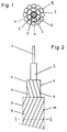
- the opposite directions of impact are 9 and 10 serving as the second and third layers 5 and 7 stranded first and second wire layers schematically shown.
- resulting high flexibility of the cable 1 becomes one Torsion of the cable 1 largely prevented and at the same time easy flexibility of the cable 1 in any transverse direction to the cable axis, but the bend of cable 1 becomes more difficult the closer the Bend comes up to the minimum bending radius because due to the tensile stress on the stainless steel wires on the Outside of the bend and the compressive stress of the same on the inside of the bend with increasing tension and Compressive stress the flexibility of the cable 1 decreases, which is particularly the case for the third layer 7 second wire layer applies.
- a kink in the cable 1 is by the two in the opposite direction stranded wire layers 5 and 7 practically completely prevented.
- the term "kink resistance" is based on the DIN standard EN 187000 referenced.
- Fig. 1 1 When using the optical cable shown in Fig. 1 1 as field cable for field cables for temporary Connection of non-stationary intended for data exchange Transceiver stations or field phones can the cable 1 if necessary also under tension e.g. be led over streets because the cable 1 for it sufficient tensile strength, sufficient Impact resistance and also sufficient cross-loading capacity has, so that even heavy vehicles over the Can drive cables. Because field cables have all sorts Obstacles must be passed, e.g. over terrain, on which are heavy animals, of course, at any time can step on the field cable, or e.g. around corners or piles or rods with a relatively small radius of curvature, is the high kink resistance of cable 1 from very special advantage.
- the optical cable 1 used as a field cable Due to the cumulative especially good tensile strength properties as well as lateral pressure resistance and high flexibility very high kink resistance of the cable 1, it is even possible the optical cable 1 used as a field cable to stretch the floor, i.e. in the air. That as a field cable Cable 1 used can be laid easily because there is hardly any possibility of damage Needs to be taken into account, which is a very ensures quick and inexpensive temporary installation is. Since the optical cable 1 is a relative has a small diameter of 4.1 mm, a relative long cable from e.g. approx. 500 m length by hand, preferably on a small cable reel, easily to the next Are transported or carried, so that the temporary laying even in rough terrain can be done easily. Due to the high flexibility of the optical cable 1 is constantly being used again no problem with the same cable.
Abstract
Description
Die Erfindung bezieht sich auf ein optisches Kabel mit mindestens einem Lichtwellenleiter, der von einer Armierungsmittel umfassenden Hülle mit mindestens zwei aus festem Material bestehenden Schichten umgeben ist, von denen die innerste Schicht von einem Lichtwellenleiter-Röhrchen gebildet ist und sich im Kern des optischen Kabels befindet sowie auf eine besondere Verwendung des Kabels. The invention relates to an optical cable at least one optical waveguide by an armouring agent comprehensive shell with at least two of solid Material existing layers is surrounded by those the innermost layer of an optical fiber tube is formed and in the core of the optical cable located as well as on a special use of the cable.
Ein optisches Kabel dieser Art ist aus dem DE-GM 9217037.4 und ein ähnliches Kabel aus der DE-OS 4401079 bekannt. Bei diesen bekannten Kabeln liegen die Armierungsmittel im wesentlichen in einer dort als "Biegeebene" bezeichneten Längsschnittfläche des Kabels, in die auch die Kabelachse fällt. Wird ein solches Kabel nun so gebogen, dass der Flächenkrümmungsradius der Längsschnittfläche im Biegebereich des Kabels an allen Stellen im wesentlichen gleich gross ist, dann setzen die Armierungsmittel des Kabels der Biegung keinen nennenswerten Widerstand entgegen, so dass der Flächenkrümmungsradius an der Biegungsstelle immer kleiner wird, bis das Kabel an dieser Stelle einknickt. Bei einer Biegung des Kabels in der Weise, dass der Flächenkrümmungsradius einer zu der genannten Längsschnittfläche rechtwinklig angeordneten zweiten Langsschnittfläche im Biegebereich des Kabels an allen Stellen im wesentlichen gleich gross ist, verhindern die Armierungsmittel hingegen sowohl weitgehend eine stärkere Biegung als auch ein Einknicken des Kabels an der Biegungsstelle. Die bekannten optischen Kabel der eingangs genannten Art haben also den Nachteil, dass sie bei einer Biegung über die besagte "Biegeebene" nicht knickfest sind, d.h. dass sie bei einer Biegung des Kabels über die besagte "Biegeebene" bis auf einen unter dem vorgeschriebenen minimalen Biegeradius des Kabels liegenden Krümmungsradius an der Biegestelle einknicken. Um ein solches Einknicken bei den bekannten Kabeln zu vermeiden, muss somit der vorgeschriebene minimale Biegeradius bei den bekannten Kabeln der eingangs genannten Art relativ gross sein und darf bei der Verlegung des Kabels im praktischen Betrieb desselben nicht unterschritten werden.An optical cable of this type is from the DE-GM 9217037.4 and a similar cable from DE-OS 4401079 known. The reinforcement means are located in these known cables essentially in a "bending plane" designated longitudinal section of the cable into which the cable axis also falls. Is such a cable now bent that the radius of curvature of the longitudinal cut surface in the bending area of the cable at all points is essentially the same size, then the reinforcement means set the cable of the bend no significant Resistance to it, so the radius of curvature at the bend point gets smaller and smaller until the cable buckles at this point. If the cable bends in such a way that the radius of curvature is one said longitudinal section surface arranged at right angles second longitudinal section in the bending area of the cable is essentially the same at all points the reinforcing agents, on the other hand, both largely a stronger bend and a kink in the cable at the bend. The known optical cables of the have the disadvantage that they with a bend over the said "bending plane" not are kink-resistant, i.e. that if there is a bend in the cable over the said "bending plane" except for one below the prescribed minimum bending radius of the cable Bend the radius of curvature at the bending point. To such a buckling in the known cables must avoid the prescribed minimum bending radius in the known cables of the aforementioned Kind of be relatively large and allowed when laying the cable in practical operation of the same will.
Für die gewöhnliche Verlegung von optischen Kabeln sind die bekannten Ausführungsformen derselben zwar durchaus geeignet und weisen für die meisten Fälle von festen und vorgeplanten Verlegungen auch einen genügend kleinen minimalen Biegeradius sowie eine genügende Knickfestigkeit auf, aber insbesondere bei z.B. nachträglichen, provisorischen oder temporären Verlegungen, z.B. eng um einen Türrahmen oder z.B. auf dem freien Feld, wo beispielsweise schwere Tiere auf das Kabel treten können, sind weder die bei den bekannten optischen Kabeln vorgeschriebenen minimalen Biegeradien, die z.B. in der Grössenordnung von 150 mm liegen können, noch die sich daraus ergebende relativ geringe Knickfestigkeit ausreichend. Knickfestigkeit muss aber gegeben sein, damit eine optimale Datenübertragung über die Lichtwellenleiter gewährleistet ist, da eingeknickte Lichtwellenleiter normalerweise keine Daten mehr übertragen können. Darüber hinaus sind die besagten vorgegebenen "Biegeebenen" der bekannten optischen Kabel der eingangs genannten Art besonders bei temporärer Verlegung, insbesondere auch bei mehrmaliger temporärer Verlegung ein und desselben Kabels, oder ganz besonders auch bei Belastung von auf dem freien Feld verlegten optischen Kabeln durch schwere Tiere von besonders grossem Nachteil, weil bei temporären oder provisorischen Verlegungen von bekannten optischen Kabeln, z.B. für die Bild-oder Nachrichtenübertragung, wegen der notwendigen Verlegung mit relativ grossen minimalen Biegeradien und dem erforderlichen Schutz des Kabels vor Beschädigungen, z.B. durch schwere bzw. knickgefährdende Belastungen, wie sie z.B. durch Tritte von schweren Tieren auftreten und zum Knicken des Kabels führen können, mit einem relativ hohen Kosten- und Arbeitsaufwand, ähnlich wie bei fest zu verlegenden optischen Kabeln, verbunden sind.For the usual laying of optical cables the known embodiments of the same indeed suitable and show for most cases of fixed and pre-planned laying also a sufficiently small minimal Bending radius and sufficient kink resistance on, but especially in e.g. subsequent, provisional or temporary relocations, e.g. tight around you Door frame or e.g. in the open field, for example heavy animals can neither step on the cable those prescribed for the known optical cables minimal bending radii, e.g. in the order of 150 mm, still the resulting relative low kink resistance sufficient. Kink resistance But must be given for optimal data transmission is guaranteed via the optical fibers, there is normally no data because of the kinked optical fiber can transmit more. In addition, the said given "bending planes" of the known optical Cables of the type mentioned above, especially for temporary ones Laying, especially with repeated temporary Laying one and the same cable, or very special even when loading optical ones installed in the open field Cables through heavy animals of a particularly large size Disadvantage because of temporary or provisional relocations from known optical cables, e.g. for the picture or Message transmission because of the necessary relocation with relatively large minimal bending radii and the necessary protection of the cable against damage, e.g. due to heavy or kink-prone loads such as these e.g. by kicking heavy animals and to Kinking the cable can result in a relatively high Costs and workload, similar to those to be installed permanently optical cables.
Der Erfindung lag daher die Aufgabe zugrunde, ein optisches Kabel der eingangs genannten Art zu schaffen, das über alle bei einem optischen Kabel möglichen Biegeebenen gebogen werden kann und dabei in jedem Fall ein geringer minimaler Biegeradius und eine entsprechend hohe Knickfestigkeit erreichbar ist. The invention was therefore based on the object of an optical To create cables of the type mentioned that across all bending levels possible with an optical cable can be bent and in any case a small one minimal bending radius and a correspondingly high kink resistance is achievable.
Erfindungsgemäss wird das mit einem optischen Kabel der eingangs genannten Art erreicht, das gekennzeichnet ist durch mindestens eine das Lichtwellenleiter-Röhrchen umgebende weitere Schicht aus im wesentlichen gleichgrosse Knickfestigkeit in allen Querrichtungen zur Kabelachse gewährleistenden metallischen Armierungsmitteln.According to the invention with an optical cable achieved type mentioned, which is marked by at least one surrounding the optical fiber tube another layer of essentially the same size Kink resistance in all transverse directions to the cable axis ensuring metallic reinforcing agents.
Hauptvorteil des vorliegenden optischen Kabels ist, dass der minimale Biegeradius durch die das Lichtwellenleiter-Röhrchen umgebende Schicht aus im wesentlichen gleichgrosse Knickfestigkeit in allen Querrichtungen zur Kabelachse gewährleistenden metallischen Armierungsmitteln um ein Vielfaches kleiner sein kann als der minimale Biegeradius der bekannten optischen Kabel. Dadurch ergibt sich natürlich auch eine entsprechend wesentlich höhere Knickfestigkeit bei dem vorliegenden optischen Kabel gegenüber den bekannten optischen Kabeln. Zusätzlich hat das vorliegende Kabel den Vorteil, dass es über alle für das Kabel möglichen Biegeebenen gebogen werden kann.The main advantage of the present optical cable is that the minimum bending radius through which the fiber optic tube surrounding layer of essentially the same size Kink resistance in all transverse directions to the cable axis ensuring metallic reinforcing agents can be many times smaller than the minimum bending radius the known optical cables. This results in of course also a correspondingly higher kink resistance compared with the present optical cable the well-known optical cables. In addition, the present Cable the advantage that it is all over the cable possible bending planes can be bent.
Bei einer bevorzugten Ausführungsform des vorliegenden optischen Kabels ist die Knickfestigkeit des Kabels bis zur Biegbarkeitsgrenze des Kabels und im Falle, dass der Biegeradius an der Biegbarkeitsgrenze kleiner als der minimal zulässige Biegeradius ist, bis zu einem minimalen Biegeradius von 20 mm, zweckmässig von 15 mm und vorzugsweise von 10 mm, gewährleist. Dies hat den besonderen Vorteil, dass der minimale Biegeradius beim vorliegenden Kabel gegenüber den bekannten Kabeln bis zum 15-fachen kleiner sein kann und damit eine relativ hohe Knickfestigkeit erreicht werden kann. Dabei hängt der minimale Biegeradius des optischen Kabels von der Schichtdicke der metallischen Armierungsmittel sowie vom Durchmesser und der Wandstärke des Lichtwellenleiter-Röhrchens ab. Diese Masse können je nach den Anforderungen, die an das optische Kabel gestellt werden, festgelegt werden. Vorzugsweise kann dabei die Knickfestigkeit des Kabels bis zur Biegbarkeitsgrenze des Kabels und im Falle, dass der Biegeradius an der Biegbarkeitsgrenze kleiner als der minimal zulässige Biegeradius ist, bis zu einem minimalen Biegeradius des Kabels vom maximal 12-fachen des Kabelradius, vorzugsweise vom maximal 8-fachen des Kabelradius, gewährleistet sein.In a preferred embodiment of the present optical cable is the kink resistance of the cable up to the flexibility limit of the cable and in the event that the Bending radius at the bend limit less than the minimum permissible bending radius is up to a minimum Bending radius of 20 mm, expediently of 15 mm and preferably of 10 mm, guaranteed. This has the special one Advantage that the minimum bending radius in the present Cables up to 15 times the known cables can be smaller and thus a relatively high kink resistance can be reached. The minimum depends Bending radius of the optical cable from the layer thickness of the metallic reinforcement as well as diameter and the wall thickness of the fiber optic tube. This Dimensions can vary depending on the requirements of the optical Cables are set, set. Preferably the kink resistance of the cable up to Bendability limit of the cable and in the event that the bending radius at the limit of flexibility less than the minimum permissible bending radius is up to a minimum Bending radius of the cable up to a maximum of 12 times the cable radius, preferably a maximum of 8 times the cable radius, to be guaranteed.
Mit besonderem Vorteil besteht das Lichtwellenleiter-Röhrchen aus Metall, vorzugsweise aus Edelstahl. Der Vorteil dieser Ausführungsform besteht darin, dass zwei übereinanderliegende rohrförmige metallische Schichten die Knickfestigkeit der inneren rohrförmigen Schicht und damit des Lichtwellenleiter-Röhrchens wesentlichen erhöht. Bei optischen Kabeln mit besonders kleinem Durchmesser kann das Lichtwellenleiter-Röhrchen vorteilhaft auch aus Kunststoff, vorzugsweise aus einem Polyamid, bestehen, so dass z.B. bei Verwendung von nur einem Lichtwellenleiter ein sehr geringer Durchmesser für das Lichtwellenleiter-Röhrchen erreicht werden kann.The fiber optic tube is particularly advantageous made of metal, preferably stainless steel. The advantage this embodiment is that two superimposed tubular metallic layers the kink resistance of the inner tubular layer and thus the optical fiber tube significantly increased. For optical cables with a particularly small diameter the fiber optic tube can be advantageous also consist of plastic, preferably of a polyamide, so that e.g. when using only one optical fiber a very small diameter for the fiber optic tube can be reached.
Vorteilhaft können ein oder mehrere Lichtwellenleiter, z.B. bis zu 24 Lichtwellenleiter, in einem Lichtwellenleiter-Röhrchen eingebracht sein, wobei der oder die Lichtwellenleiter in bekannter Weise eine minimale Ueberlänge von z.B. mindestens 0,5 ‰, vorzugsweise über 3 ‰ , aufweisen können, um nach starken Zugbelastungen weiterhin voll funktionsfähig bleiben zu können. Ausserdem können die aus Metall bzw. Edelstahl sowie auch die aus Kunststoff bestehenden Lichtwellenleiter-Röhrchen vorteilhaft in bekannter Weise mit einem Gel ausgefüllt sein.One or more optical waveguides, e.g. up to 24 fiber optic cables in one fiber optic tube be introduced, the or the Optical fibers in a known manner, a minimal excess length from e.g. at least 0.5 ‰, preferably about 3 ‰, can have after strong tensile loads to remain fully functional. Moreover can the metal or stainless steel as well as the plastic fiber optic tubes advantageously filled with a gel in a known manner be.
Bei einer vorteilhaften Ausführungsform des vorliegenden Kabels umfasst die weitere Schicht aus metallischen Armierungsmitteln mindestens eine Lage aus wenigstens vier, vorzugsweise aus mehr als fünf, im wesentlichen parallel zueinander wendelförmig verlaufenden Runddrähten und/oder mindestens eine Lage aus wenigstens einem Profildraht mit vorzugsweise im wesentlichen quadratischem oder rechtekkigem Querschnitt. Damit kann schon bei kleinen Kabeldurchmessern eine maximale Zugfestigkeit von 6000 N erreicht werden, was eine bis um das 2-fache höhere maximale Zugbelastbarkeit des vorliegenden optischen Kabels im Vergleich zu den bekannten optischen Kabeln darstellt. Aehnliches gilt auch für die maximale Querbelastbarkeit. Durch den im wesentlichen parallelen wendelförmigen Verlauf der Drähte um das Lichtwellenleiter-Röhrchen entsteht eine rohrartige Schicht, die den Vorteil hat, dass sie derart flexibel ist, dass sie das Biegen des optischen Kabels in genügender Weise erlaubt, aber ein zum Knicken des Kabels führendes Biegen praktisch verhindert. Allgemein ist ein wesentlicher Vorteil dieser Ausführungsform des vorliegenden Kabels, dass sie hohe Belastungsgrenzen für Zugbelastung sowie Querdruckbelastung und ausserdem Nagesicherheit, Schnitt- und Schlagfestigkeit ermöglicht. Vorteilhafterweise können dabei verschiedene Anforderungen an die maximale Zugbelastung und an den maximalen Querdruck durch eine entsprechende Wahl des Schlagwinkels der wendelförmig verlaufenden Drähte erfüllt werden, wobei der Schlagwinkel vorzugsweise im Bereich von 10° bis 30° liegt. Drahtlagen aus Profildraht mit im wesentlichen quadratischen Querschnitt können vorteilhaft seitenschlüssig aneinander angrenzende Windungen des Profildrahtes aufweisen. Bei entsprechender Anforderung an das optische Kabel kann ferner dadurch eine besonders hohe Knickfestigkeit erreicht werden, dass die metallischen Armierungsmittel Profildrähte umfassen, die die Form eines flachen Metallbandes besitzen und damit den Querschnitt eines flachen Rechteckes aufweisen, wobei der metallbandförmige Profildraht oder auch mehrere metallbandförmige Profildrähte schraubenlinienförmig auf das Lichtwellenleiter-Röhrchen aufgebracht sind. Mit besonderem Vorteil kann eine erste Lage aus dem genannten metallbandförmigen Profildraht bestehen und darüber eine Lage Runddrähte oder Profildrähte mit im wesentlichen quadratischem Querschnitt aufgebracht sein, wodurch die Knickfestigkeit noch weiter erhöht werden kann und auch eine ganz besonders hohe maximale Zug- oder Querbelastung möglich ist. Aehnliches gilt auch, wenn die erste Lage aus wendelförmig verlaufenden Runddrähten oder Profildrähten mit im wesentlichen quadratischem Querschnitt besteht und darüber eine Lage aus dem genannten metallbandförmigen Profildraht liegt.In an advantageous embodiment of the present Cable encompasses the additional layer of metallic reinforcement at least one layer of at least four, preferably more than five, substantially parallel round wires running helically to one another and / or with at least one layer of at least one profile wire preferably substantially square or rectangular Cross-section. This means that even with small cable diameters reaches a maximum tensile strength of 6000 N. be what a maximum up to 2 times higher Tensile strength of the present optical cable in Compared to the known optical cables. The same applies to the maximum transverse load capacity. Due to the essentially parallel helical course of the wires around the fiber optic tube a tubular layer that has the advantage that it is so flexible that it can bend the optical Cable allowed in a sufficient way, but one to Kinking the cable practically prevents bending. Generally, an essential advantage of this embodiment is of the present cable that they have high load limits for tensile and transverse pressure loads and also gnawing security, cut and impact resistance enables. Different ones can advantageously be used Maximum tensile load requirements and to the maximum transverse pressure through an appropriate choice the lay angle of the helical wires are met, the impact angle preferably in Range is from 10 ° to 30 °. Wire layers made from profiled wire with a substantially square cross section can be advantageous mutually adjacent turns of the profile wire. If requested to the optical cable can also be a special high kink resistance that can be achieved metallic reinforcing agents include profile wires that have the shape of a flat metal band and thus have the cross section of a flat rectangle, wherein the metal band-shaped profile wire or several metal band-shaped Profile wires helically the fiber optic tubes are applied. With special Advantage can be a first layer from the above metal ribbon-shaped profile wire exist and a Lay round wires or profile wires with essentially square cross-section can be applied, whereby the Kink resistance can be increased even further a particularly high maximum tensile or transverse load is possible. The same applies if the first layer made of helical round wires or profile wires with a substantially square cross section and above it a layer of the metal strip-shaped Profile wire lies.
Mit besonderem Vorteil ist bei der Verwendung von Runddrähten
zur Armierung der Durchmesser der Drähte in den
einzelnen Drahtlagen mindestens zu dem (1/K)-fachen des
Innendurchmessers der betreffenden Drahtlage festzulegen,
wenn
Mit grossem Vorteil kann die weitere Schicht aus metallischen Armierungsmitteln mindestens Zwei Lagen aus jeweils wenigstens vier, vorzugsweise aus mehr als fünf, im wesentlichen parallel zueinander wendelförmig verlaufenden Runddrähten oder Profildrähten mit im wesentlichen quadratischem Querschnitt umfassen, wobei übereinanderliegende Drahtlagen in entgegengesetzter Schlagrichtung verseilt sein. Dadurch wird nicht nur die Flexibilität des vorliegenden Kabels erhöht sondern auch die Knickfestigkeit sowie die maximale Zugfestigkeit und die maximale Querbelastbarkeit nebst verbesserter Schlagfestigkeit entsprechend zusätzlich erhöht. Damit kann eine maximale Zugfestigkeit von 9000 N erreicht werden, was eine bis um das 3-fache höhere maximale Zugbelastbarkeit von dem vorliegenden optischen Kabel gegenüber den bekannten optischen Kabeln darstellt. Aehnliches gilt auch für die maximale Querbelastbarkeit.The additional layer of metallic can be very advantageous Reinforcing agents at least two layers each at least four, preferably more than five, substantially parallel to each other helically Round wires or profile wires with essentially square Include cross-section, being superimposed Wire layers stranded in the opposite direction be. This not only increases the flexibility of the existing cable also increases the kink resistance as well as the maximum tensile strength and the maximum Cross load capacity with improved impact resistance increased accordingly accordingly. So that a maximum Tensile strength of 9000 N can be achieved, which is up to 3 times the maximum tensile strength of the present optical cable compared to the known optical Represents cables. The same applies to the maximum Cross-loading.
Zur Vermeidung hoher Materialkosten und Erzielung eines insbesondere bei temporären Verlegungen wichtigen möglichst geringen Kabelgewichtes sollte die weitere Schicht aus metallischen Armierungsmitteln zweckmässig nicht mehr als drei Lagen aus verseilten Runddrähten und/oder Profildrähten mit im wesentlichen quadratischem oder rechteckigem Querschnitt umfassen, weil der Kabeldurchmesser sonst zu gross wird. Das gilt insbesondere deswegen, weil das vorliegende optische Kabel in jedem Fall einen relativ kleinen minimalen Biegeradius und eine entsprechend hohe Knickfestigkeit aufweisen sollte.To avoid high material costs and to achieve a particularly important for temporary relocations if possible The additional layer should be light in weight expediently no longer from metallic reinforcing agents as three layers of stranded round wires and / or profile wires with essentially square or rectangular Cross section include because of the cable diameter otherwise it gets too big. This is especially true because the present optical cable in any case a relative small minimum bend radius and one accordingly should have high kink resistance.
Je nach Anforderung an das vorliegende Kabel kann die weitere Schicht aus metallischen Armierungsmitteln aus Runddrähten und/oder mindestens einem Profildraht mit vorzugsweise im wesentlichen quadratischem oder rechtekkigem Querschnitt aufgebaut sein, wobei die Drähte vorteilhaft aus Stahl, Edelstahl, Federstahl, Aluminium, Aldrey oder einer entsprechenden aluminiumummantelten Drahtsorte bestehen können. Damit kann vorteilhaft je nach Anforderung an das vorliegende Kabel z.B. eine hohe Korrosionsfestigkeit erreicht werden, beispielsweise bei der Ausführung aus den genannten Aluminiumlegierungen, aus Aluminium oder aus Edelstahl, und/oder eine hohe elektrische Leitfähigkeit, z.B. bei der Ausführung aus den genannten Aluminiumlegierungen oder aus Aluminium, und/oder eine hohe Zugfestigkeit, z.B. bei der Ausführung aus Edelstahl, oder eine besondere Erhöhung der Knickfestigkeit, beispielsweise bei der Ausführung aus Federstahl, oder ein besonders kostengünstiger Aufbau, z.B. bei der Ausführung aus Stahl, erzielt werden. Bei der Verwendung von aluminiumummantelten Drähten lassen sich Kombinationen der genannten Vorteile, insbesondere eine Kombination von hoher Korrosionsfestigkeit, hoher elektrischer Leitfähigkeit und hoher Zugfestigkeit erzielen.Depending on the requirements of the present cable, the another layer of metallic reinforcement Round wires and / or at least one profile wire with preferably substantially square or rectangular Cross-section can be constructed, the wires being advantageous made of steel, stainless steel, spring steel, aluminum, Aldrey or an equivalent aluminum sheathed Wire type can exist. This can be advantageous after requesting the present cable e.g. a high Corrosion resistance can be achieved, for example at the execution from the named aluminum alloys, made of aluminum or stainless steel, and / or a high electrical conductivity, e.g. when running out the aluminum alloys mentioned or made of aluminum, and / or high tensile strength, e.g. in execution made of stainless steel, or a special increase in kink resistance, for example in the version made of spring steel, or a particularly inexpensive construction, e.g. in the steel version. In the Use of aluminum sheathed wires Combinations of the advantages mentioned, especially one Combination of high corrosion resistance, high electrical Achieve conductivity and high tensile strength.
Vorteilhaft kann die weitere Schicht aus metallischen Armierungsmitteln mindestens eine Lage aus Runddraht oder Profildraht mit vorzugsweise im wesentlichen quadratischem Querschnitt umfassen und die Durchmesser bzw. Diagonalen der Runddrähte bzw. Profildrähte jeweils in ein und derselben Drahtlage gleich sein und zweckmässig in einem Bereich von 0,2 bis 2,5 mm, vorzugsweise 0,5 bis 1,5 mm, liegen. Dadurch ergeben sich relativ dünne optische Kabel, die insbesondere für eine temporäre Verlegung von Vorteil sind, weil sie damit in grosser Länge auf Kabelrollen aufgebracht werden können und trotzdem noch leicht genug sein können, um von Hand verlegt zu werden. Da bei dem vorliegenden Kabel sehr geringe minimale Biegeradien möglich sind, kann der Kern der Kabelrolle sehr klein gehalten werden und die Kabelrolle dabei ein relativ langes optisches Kabel von z.B. bis zu 1000 m Länge aufnehmen. Dabei kann ein 1000 m langes Kabel nach der vorliegenden Erfindung inklusive Kabelrolle ein Gewicht von weniger als 20 Kg aufweisen, was eine leichte manuelle Transportierbarkeit auch von längeren optischen Kabeln selbst im unwegsamen Gelände ermöglicht. The further layer of metallic reinforcing agents can be advantageous at least one layer of round wire or Profile wire with preferably essentially square Include cross-section and the diameters or diagonals of the round wires or profile wires in each case and the same wire layer are the same and expedient in a range of 0.2 to 2.5 mm, preferably 0.5 to 1.5 mm. This results in relatively thin optical Cables, especially for temporary laying are an advantage because they are long on cable reels can be applied and still can be light enough to be laid by hand. Because the present cable has very low minimum bending radii are possible, the core of the cable reel can be very be kept small and the cable reel a relative long optical cable from e.g. up to 1000 m in length record, tape. A 1000 m long cable can be used present invention including cable reel a weight of less than 20 kg, which is a light manual Transportability even of longer optical cables even in rough terrain.
Mit besonderem Vorteil kann die weitere Schicht aus metallischen Armierungsmitteln mindestens eine Drahtlage aus einem Profildraht mit vorzugsweise im wesentlichen quadratischem oder rechteckigem Querschnitt umfassen und die gegenüberliegenden Längsseiten des Profildrahtes jeweils nach einer Windung vorzugsweise im wesentlichen formschlüssig aneinander angrenzen. Bei der sich dadurch ergebenden von einer Drahtlage gebildeten rohrartigen Form der weiteren Schicht bleibt der Vorteil einer guten Flexibilität des optischen Kabels erhalten, und auch bei dieser Ausbildungsform ist ein relativ kleiner minimaler Biegeradius und damit eine entsprechend hohe Knickfestigkeit möglich.The further layer of metallic can be particularly advantageous Reinforcing agents at least one wire layer from a profile wire with preferably essentially include square or rectangular cross-section and the opposite long sides of the profile wire each after a turn preferably essentially positively adjoin each other. In the case of this resulting tubular formed by a wire layer The form of the further layer remains the advantage of a good one Preserve flexibility of the optical cable, and also at this form of training is a relatively small minimum Bending radius and thus a correspondingly high kink resistance possible.
Bei einer weiteren vorteilhaften Ausbildungsform des vorliegenden Kabels umfasst die weitere Schicht einen Profildraht mit im wesentlichen rechteckigen Querschnitt, wobei die aneinander angrenzenden Längsseiten des Profildrahtes sich überlappen und zweckmässig an den oder nahe den Längsseiten des Profildrahtes Mittel zur Beibehaltung der Ueberlappung bei Biegebeanspruchung des Kabels vorgesehen sind. Diese Mittel zur Beibehaltung der Ueberlappung können z.B. vorteilhaft darin bestehen, dass möglichst nahe entlang der einen Längsseite der breiten Seitenfläche des rechteckförmigen Profildrahtes eine U-förmige Vertiefung angebracht ist, die z.B. bis in die Mitte der breiten Seitenfläche reicht, wobei diese U-förmige Vertiefung auf der gegenüberliegenden breiten Seitenfläche als U-förmige Ausbuchtung aus dieser breiten Seitenfläche hinausragt, und dass auf der Seitenfläche mit der U-förmigen Vertiefung möglichst nahe entlang der anderen Längsseite dieser breiten Seitenfläche des rechteckförmigen Profildrahtes eine z.B. halbkreisförmige Vertiefung angebracht ist, die dieselbe Tiefe wie die U-förmige Vertiefung aufweist, und die z.B. über einiges weniger als einem Viertel der breiten Seitenfläche reicht, wobei diese z.B. halbkreisförmige Vertiefung auf der gegenüberliegenden breiten Seitenfläche als z.B. halbkreisförmige Ausbuchtung aus dieser breiten Seitenfläche hinausragt, so dass bei der Ueberlappung die z.B. halbkreisförmige Ausbuchtung der breiten Seitenfläche jeweils nach einer Windung des Profildrahtes in die auf der gegenüberliegenden Längsseite liegende U-förmige Vertiefung dieser Seitenfläche eingreift und damit eine stabile rohrförmige als Armierung dienende Schicht geschaffen ist, bei der bei Biegung des optisches Kabels die Ueberlappung innerhalb der Länge der U-förmigen abzüglich der z.B. halbkreisförmigen Vertiefung bzw. Ausbuchtung variieren kann. Damit kann der äussere Krümmungsradius des gebogenen Kabels an der Biegungsstelle in dem Umfang grösser sein als der innere Krümmungsradius des gebogenen Kabels an der gleichen Biegungsstelle, ohne dass dabei die Schicht aus dem Profildraht schon einer Biegebelastung ausgesetzt sein muss, in dem die genannte Länge der U-förmigen abzüglich der z.B. halbkreisförmigen Vertiefung bzw. Ausbuchtung variieren kann. Bei einer anderen vorteilhaften Ausführungsform der Mittel zur Beibehaltung der Ueberlappung bei Biegebeanspruchung können zwei Profildrähte mit im wesentlichen rechteckigem Querschnitt verwendet werden, die mit derartigen Ausnehmungen versehen sind, dass der tragende Querschnitt des Profildrahtes U-förmig ist, wobei die Schenkel der U-Formen in die Ausnehmungen der jeweils benachbarten Profildrahtwindungen eingreifen. Damit kann die Ueberlappung bei Biegung des optisches Kabels variieren und somit der innere Krümmungsradius des gebogenen Kabels kleiner als der äussere Krümmungsradius des gebogenen Kabels an der Biegungsstelle sein, ohne dass dabei die Schicht aus den Profildrähten bereits einer Biegebelastung ausgesetzt sein muss. Bei der Ausführungsform mit zwei U-förmigen Profildrähten kann der minimale Biegeradius des Kabels kleiner sein als bei der vorgenannten Ausführungsform mit nur einem Profildraht mit zwei Vertiefungen in der breiten Seitenfläche, ohne dass dabei die Schicht aus Profildraht schon einer Biegebelastung ausgesetzt sein muss. In a further advantageous embodiment of the present Cable, the further layer comprises a profiled wire with a substantially rectangular cross-section, the adjacent longitudinal sides of the profile wire overlap and expediently on the or means for maintaining near the long sides of the profiled wire the overlap when the cable is subjected to bending stress are provided. This means of maintaining the Overlaps can e.g. advantageously consist in that as close as possible along one long side of the broad Side surface of the rectangular profile wire a U-shaped Recess, which e.g. until the Middle of the wide side surface extends, this being U-shaped Deepening on the opposite broad Side surface as a U-shaped bulge from this wide Side surface protrudes, and that on the side surface with the U-shaped depression as close as possible along the other long side of this wide side surface of the rectangular Profile wire e.g. semicircular depression attached, the same depth as the U-shaped Has recess, and which e.g. about some less than a quarter of the wide side surface is sufficient, e.g. semicircular depression the opposite wide side surface as e.g. semicircular bulge from this wide side surface protrudes so that when overlapping the e.g. semicircular bulge of the wide side surface in each case after a turn of the profile wire in the on the opposite U-shaped recess engages this side surface and thus a stable tubular layer serving as reinforcement is where the overlap when the optical cable is bent within the length of the U-shaped minus the e.g. semicircular depression or bulge vary can. This allows the outer radius of curvature of the bent cable at the bend point to the extent be larger than the inner radius of curvature of the curved Cable at the same bend point without doing so the layer of the profile wire is already subjected to a bending load must be exposed to the length of the U-shaped minus e.g. semicircular depression or bulge may vary. Another one advantageous embodiment of the means for retention the overlap under bending stress can be two profile wires with a substantially rectangular cross section are used, which are provided with such recesses are that the load-bearing cross-section of the profile wire Is U-shaped, with the legs of the U-shapes in the recesses of the adjacent profile wire turns intervention. So that the overlap when bending the optical cable vary and thus the inner radius of curvature of the bent cable smaller than the outer one Radius of curvature of the bent cable at the bend point be without removing the layer from the profile wires must already be subjected to a bending load. In the embodiment with two U-shaped profile wires the minimum bending radius of the cable can be smaller than in the aforementioned embodiment with only one profile wire with two depressions in the wide side surface, without the layer of profile wire already must be subjected to a bending load.
Bei einer weiteren bevorzugten Ausführungsform ist die genannte, aus mindestens zwei Schichten bestehende Hülle des Lichtwellenleiters von einer Ummantelung aus Kunststoff, vorzugsweise aus Polyurethan, umschlossen. Dies hat nicht nur den Vorteil einer elektrischen Isolation des optischen Kabels sondern auch den weiteren Vorteil, dass beim Einsatz des optischen Kabels auf freiem Feld eine Verschmutzung der Aussenseite der Armierung verhindert wird. Zusätzlich bildet die Ummantelung natürlich auch einen erhöhten Korrosionsschutz und kann ausserdem bei der Verwendung eines entsprechenden Kunststoffes auch einen Säureschutz bieten. Die Ummantelung kann u.a. auch aus einem flammenwidrigen Kunststoff ausgeführt und damit bis zu einem gewissen Grad feuerfest sein, was insbesondere auch von Vorteil sein kann, wenn das Lichtwellenleiter-Röhrchen aus Kunststoff besteht.In a further preferred embodiment, the called, consisting of at least two layers the optical fiber from a plastic sheathing, preferably made of polyurethane. This not only has the advantage of electrical insulation of the optical cable but also the further advantage that when using the optical cable in an open field prevents contamination of the outside of the reinforcement becomes. In addition, the sheathing naturally forms also increased corrosion protection and can also when using an appropriate plastic too provide acid protection. The casing can include also made of a flame-retardant plastic and therefore be fireproof to a certain extent, which in particular can also be advantageous if the fiber optic tube is made of plastic.
Mit besonderem Vorteil kann die Ummantelung auf ihrer Innenseite durch mindestens einen schraubenlinienförmig verlaufenden Metalldraht, vorzugsweise einen Stahldraht oder Federstahldraht, verstärkt sein, was abermals eine zusätzliche Erhöhung der Knickfestigkeit ergibt. Insbesondere bei dem optischen Kabel, bei dem die Schicht aus Armierungsmitteln nur eine Lage oder eine äussere Lage aus Profildraht mit im wesentlichen rechteckigem Querschnitt umfasst, der z.B. metallbandförmig aufgebaut ist, und bei dem sich gegenüberliegende Längsseiten jeweils nach einer Windung überlappen, verhindert die Verstärkung der Ummantelung zudem weitgehend die Möglichkeit eines Aufbrechens der Ueberlappungsstellen des Profildrahtes an der Aussenseite der Biegung des Kabels bei starker Biegung desselben.The sheathing on the inside can be particularly advantageous by at least one helical running metal wire, preferably a steel wire or spring steel wire, which is another one results in an additional increase in kink resistance. Especially for the optical cable where the layer is made of Reinforcing agents only one layer or an outer layer made of profiled wire with an essentially rectangular cross-section which e.g. is constructed in the form of a metal band, and the opposite long sides each overlap after one turn prevents reinforcement the casing also largely the possibility of a Breaking open the overlap points of the profile wire the outside of the bend of the cable in case of a strong bend the same.
Der Durchmesser des vorliegenden Kabels kann vorteilhaft im Bereich zwischen 1 bis 6 mm, vorzugsweise zwischen 1,5 bis 3 mm, liegen und damit relativ klein sein, was insbesondere bei temporärer Verlegung des Kabels für dessen manuellen Transport im Hinblick auf das Kabelgewicht und die zu transportierende höchstmögliche Kabellänge von besonderem Vorteil ist. Bei einem im unteren Teil des angegebenen Durchmesserbereiches liegenden Kabeldurchmesser von z.B. 1,5 mm kann natürlich auch der minimale Biegeradius entsprechend klein und damit auch die Knickfestigkeit entsprechend gross sein und ausserdem die Kabellänge bei vorgegebenem Maximalgewicht des Kabels relativ gross sein.The diameter of the present cable can be advantageous in the range between 1 to 6 mm, preferably between 1.5 up to 3 mm, and thus be relatively small, which in particular if the cable is temporarily laid for it manual transport in terms of cable weight and the maximum possible cable length to be transported is particularly important Advantage is. At one in the lower part of the specified Diameter range lying cable diameter from e.g. The minimum bending radius can of course also be 1.5 mm correspondingly small and therefore also the kink resistance be correspondingly large and also the cable length relatively large given the maximum weight of the cable be.
Die Erfindung betrifft weiter die Verwendung des vorliegenden Kabels als Feldkabel für Feldleitungen zur temporären Verbindung von nichtstationären zum Datenaustausch vorgesehenen Sende/Empfangs-Stationen oder Feldtelefonen. Bei dieser Verwendung kommen alle genannten Vorteile eines leichten Transportes von Hand, eines besonders kleinen minimalen Biegeradius und der entsprechend hohen Knickfestigkeit, einer hohen Belastbarkeit auf Zug und Querdruck und einer guten Schlagfestigkeit voll zur Geltung.The invention further relates to the use of the present Cables as field cables for field lines for temporary Connection of non-stationary for data exchange provided send / receive stations or field telephones. With this use, all the advantages mentioned come easy transport by hand, a particularly small one minimum bending radius and the correspondingly high one Kink resistance, high tensile strength and tensile strength Cross pressure and a good impact resistance to their full advantage.
Anhand der nachstehenden Figuren ist die Erfindung im folgenden an einem Ausführungsbeispiel näher erläutert.Based on the following figures, the invention is in following explained in more detail using an exemplary embodiment.
Es zeigen
- Fig.1
- ein Ausführungsbeispiel eines optischen Kabels nach der Erfindung mit einer aus drei Schichten bestehenden, einen Lichtwellenleiter umgebenden Hülle, im Schnitt in der in Fig. 2 gezeigten Schnittebene I-I,
- Fig.2
- eine Seitenansicht des in Fig.1 gezeigten Kabels mit der Schnittebene I-I.
- Fig. 1
- 1 shows an exemplary embodiment of an optical cable according to the invention with a sheath consisting of three layers and surrounding an optical waveguide, on average in the sectional plane II shown in FIG. 2,
- Fig. 2
- a side view of the cable shown in Figure 1 with the section plane II.
Das in Fig. 1 gezeigte optische Kabel 1 besteht aus einem
Lichtwellenleiter 2, der innerhalb eines als Lichtwellenleiter-Röhrchen
aus Edelstahl ausgebildeten und als Armierungsmittel
dienenden ersten Schicht 3 mit einer Ueberlänge
von mindestens 0,5 ‰, vorzugsweise über 3 ‰,
eingebracht ist, so dass der Lichtwellenleiter 2 auch
nach einer Zugbelastung oder Wärmeausdehnung des Kabels 1
weiterhin voll funktionsfähig bleibt. Der Hohlraum 4 ist
zwischen dem Lichtwellenleiter 2 und dem die erste
Schicht 3 bildenden Lichtwellenleiter-Röhrchen zur Verhinderung
eines eventuellen Eindringens z.B. von Kondenswasser
oder von Feuchtigkeit, die die Uebertragungsfähigkeit
des Lichtwellenleiters 2 durch unerwünschte Spiegelungseffekte
stark beeinträchtigen oder verhindern könnte,
mit einem Gel gefüllt. Die Wandstärke des die erste
Schicht 3 bildenden Lichtwellenleiter-Röhrchens, die bei
dem vorliegenden Kabel vorzugsweise im Bereich von 0,05
bis 0,3 mm liegen kann, beträgt 0,1 mm, wobei der Durchmesser
des die erste Schicht 3 bildenden Lichtwellenleiter-Röhrchens,
der beim vorliegenden Kabel vorzugsweise
im Bereich von 0,8 bis 3 mm liegen kann, 0,9 mm beträgt.
Das Lichtwellenleiter-Röhrchen 3 zeichnet sich durch einen
minimalen Biegeradius vom 15 mm aus. Zur Erreichung
einer grossen Knickfestigkeit ist über der den Kern des
Kabels 1 bildenden, als Lichtwellenleiter-Röhrchen ausgebildeten
ersten Schicht 3 eine die erste Drahtlage bildende
zweite Schicht 5 von sechs durchmessergleichen
Edelstahldrähten 6 in einer ersten Schlagrichtung mit einem
Schlagwinkel von 22,5° und eine die zweite Drahtlage
bildende dritte Schicht 7 von zwölf durchmessergleichen
Edelstahldrähten 8 in zur ersten Schlagrichtung entgegengesetzter
Schlagrichtung mit einem Schlagwinkel von 21,2°
aufgebracht. Die erste Lage 5 aus Edelstahldrähten 6 und
die zweite Lage 7 aus Edelstahldrähten 8 haben dabei alle
den gleichen Durchmesser von 0,8 mm. Der minimale Biegeradius
des Kabels 1 liegt dabei bei 19 mm, so dass das
Kabel 1 eine sehr hohe Knickfestigkeit hat und eine hohe
Flexibilität aufweist. Die maximale Zugbelastbarkeit des
Kabels 1 liegt bei 6000 N und die maximale Querbelastbarkeit
bei 400'000 N/m, so dass das Kabel 1 in allen Richtungen
extremen Belastungen standhalten kann. Insbesondere
bei der temporären Verlegung des optischen Kabels 1 im
freien Feld ist ausserdem die hohe Schlagfestigkeit von
besonderem Vorteil.The
In Fig. 2 sind die entgegengesetzten Schlagrichtungen 9
und 10 der als zweite und dritte Schicht 5 und 7 dienenden
verseilten ersten und zweiten Drahtlage schematisch
dargestellt. Durch die sich bei in entgegengesetzter
Schlagrichtung 9 und 10 der verseilten Edelstahldrähte 6
und 8 ergebende hohe Flexibilität des Kabels 1 wird eine
Torsion des Kabels 1 weitgehend verhindert und gleichzeitig
eine leichte Biegbarkeit des Kabels 1 in jeder Querrichtung
zur Kabelachse ermöglicht, wobei aber die Biegung
des Kabels 1 um so schwieriger wird, je näher die
Biegung an den minimalen Biegeradius herankommt, weil
durch die Zugbeanspruchung der Edelstahldrähte an der
Aussenseite der Biegung und die Druckbeanspruchung derselben
an der Innenseite der Biegung mit steigender Zug- und
Druckbeanspruchung die Flexibilität des Kabels 1
sinkt, was insbesondere für die die dritte Schicht 7 bildende
zweite Drahtlage gilt. Ein Einknicken des Kabels 1
wird durch die beiden in entgegengesetzter Schlagrichtung
verseilten Drahtlagen 5 und 7 praktisch vollständig verhindert.
Zur Messung der Knickfestigkeit und der Definition
des Begriffes "Knickfestigkeit" wird auf die DIN-Norm
EN 187000 verwiesen.In FIG. 2, the opposite directions of impact are 9
and 10 serving as the second and
Bei der Verwendung des in Fig. 1 gezeigten optischen Kabels
1 als Feldkabel für Feldleitungen zur temporären
Verbindung von nichtstationären zum Datenaustausch vorgesehenen
Sende-/Empfangs-Stationen oder Feldtelefonen kann
das Kabel 1 erforderlichenfalls auch unter Zugspannung
z.B. über Strassen geführt werden, weil das Kabel 1 dafür
eine ausreichende Zugbelastbarkeit, eine genügende
Schlagfestigkeit und auch eine ausreichende Querbelastbarkeit
aufweist, so dass auch schwere Fahrzeuge über das
Kabel fahren können. Da Feldkabel über alle möglichen
Hindernisse geführt werden müssen, z.B. über Gelände, auf
dem sich schwere Tiere befinden, die natürlich jederzeit
auf das Feldkabel treten können, oder z.B. um Hausecken
oder Pfähle oder Stangen mit relativ geringem Krümmungsradius,
ist die hohe Knickfestigkeit des Kabels 1 von
ganz besonderem Vorteil. Durch die sich kumulierenden besonders
guten Eigenschaften in Bezug auf Zugfestigkeit
sowie Querdruckbelastbarkeit und hoher Flexibilität bei
sehr hoher Knickfestigkeit des Kabels 1 ist es sogar möglich,
das als Feldkabel verwendete optische Kabel 1 über
dem Boden, also in der Luft, zu spannen. Das als Feldkabel
verwendete Kabel 1 kann auf einfache Weise verlegt
werden, da auf allfällige Beschädigungsmöglichkeiten kaum
Rücksicht genommen werden braucht, womit eine sehr
schnelle und kostengünstige temporäre Verlegbarkeit gewährleistet
ist. Da das optische Kabel 1 einen relativ
kleinen Durchmesser von 4,1 mm aufweist, kann ein relativ
langes Kabel von z.B. ca. 500 m Länge von Hand, vorzugsweise
auf einer kleinen Kabelrolle, leicht an den nächsten
Verlegungsort transportiert bzw. getragen werden, so
dass die temporäre Verlegung auch im unwegsamen Gelände
ohne weiteres erfolgen kann. Durch die hohe Flexibilität
des optischen Kabels 1 bietet der laufend erneute Einsatz
desselben Kabels keinerlei Schwierigkeiten. When using the optical cable shown in Fig. 1
1 as field cable for field cables for temporary
Connection of non-stationary intended for data exchange
Transceiver stations or field phones can
the
- 11
- = optisches Kabel= optical cable
- 22nd
- = Lichtwellenleiter= Optical fiber
- 33rd
- = erste Schicht bzw. Lichtwellenleiter-Röhrchen= first layer or fiber optic tube
- 44th
- = Hohlraum zwischen Lichtwellenleiter u. erster Schicht= Cavity between optical fiber u. first layer
- 55
- = zweite weitere Schicht bzw. erste Drahtlage= second additional layer or first wire layer
- 66
- = Edelstahldrähte der zweiten Schicht= Stainless steel wires of the second layer
- 77
- = dritte weitere Schicht bzw. zweite Drahtlage= third additional layer or second wire layer
- 88th
- = Edelstahldrähte der dritten Schicht= Stainless steel wires of the third layer
- 99
- = Schlagrichtung der ersten Drahtlage= Lay direction of the first wire layer
- 1010th
- = entgegengesetzte Schlagrichtung der zweiten Drahtlage= opposite lay direction of the second wire layer
Claims (16)
Applications Claiming Priority (3)
| Application Number | Priority Date | Filing Date | Title |
|---|---|---|---|
| CH151996 | 1996-06-18 | ||
| CH1519/96 | 1996-06-18 | ||
| CH01519/96A CH689358A5 (en) | 1996-06-18 | 1996-06-18 | Optical cable with armouring and using the same. |
Publications (3)
| Publication Number | Publication Date |
|---|---|
| EP0816885A2 true EP0816885A2 (en) | 1998-01-07 |
| EP0816885A3 EP0816885A3 (en) | 1998-09-16 |
| EP0816885B1 EP0816885B1 (en) | 2001-10-31 |
Family
ID=4212343
Family Applications (1)
| Application Number | Title | Priority Date | Filing Date |
|---|---|---|---|
| EP97109340A Expired - Lifetime EP0816885B1 (en) | 1996-06-18 | 1997-06-10 | Optical cable with armouring and use of the same |
Country Status (5)
| Country | Link |
|---|---|
| EP (1) | EP0816885B1 (en) |
| AT (1) | ATE208051T1 (en) |
| CH (1) | CH689358A5 (en) |
| DE (1) | DE59705143D1 (en) |
| DK (1) | DK0816885T3 (en) |
Cited By (4)
| Publication number | Priority date | Publication date | Assignee | Title |
|---|---|---|---|---|
| EP1717620A1 (en) * | 2005-04-27 | 2006-11-02 | Run Chi Hsu | Anti-twisting optical fiber cable |
| CN108802936A (en) * | 2018-07-05 | 2018-11-13 | 佛山市易轩软件科技有限公司 | A kind of reinforced optical cable of radiation hardness bending resistance |
| EP3674761A1 (en) * | 2018-12-31 | 2020-07-01 | Sterlite Technologies Limited | Unitube optical fiber cable |
| CN113644102A (en) * | 2021-08-10 | 2021-11-12 | 京东方科技集团股份有限公司 | Display module, preparation method thereof and display device |
Citations (11)
| Publication number | Priority date | Publication date | Assignee | Title |
|---|---|---|---|---|
| DE2628070B1 (en) * | 1976-06-21 | 1977-08-11 | Siemens Ag | Single core optical cable |
| GB2010528A (en) * | 1977-12-16 | 1979-06-27 | Post Office | Underwater Cable |
| EP0023154A1 (en) * | 1979-07-23 | 1981-01-28 | PIRELLI GENERAL plc | Optical fibres cable and method of manufacturing it |
| GB2105865A (en) * | 1982-07-09 | 1983-03-30 | Philips Nv | Optical communication cable having a light wave guide and a tensile secondary coating |
| FR2559592A1 (en) * | 1984-02-10 | 1985-08-16 | Cables Electro Telecommunicati | Single-fibre optical cable and its use for guiding a missile in flight |
| US4606604A (en) * | 1984-05-16 | 1986-08-19 | Optelecom, Inc. | Optical fiber submarine cable and method of making |
| EP0405716A2 (en) * | 1989-06-29 | 1991-01-02 | AT&T Corp. | Coilable torque-balanced cable and method of manufacture |
| EP0405851A1 (en) * | 1989-06-30 | 1991-01-02 | AT&T Corp. | Cable having non-metallic armoring layer |
| EP0541198A1 (en) * | 1991-10-30 | 1993-05-12 | AT&T Corp. | Steam-resistant cable such as steam-resistant optical fiber cable |
| DE4228272A1 (en) * | 1992-08-26 | 1994-03-03 | Siemens Ag | Optical cable with protective layer preventing ingress of water - has corrosion proof steel wires around wave guide as reinforcement |
| DE4337180A1 (en) * | 1993-10-30 | 1995-06-14 | Felten & Guilleaume Energie | Multi-core flexible power cable with integrated fiber optic cables |
-
1996
- 1996-06-18 CH CH01519/96A patent/CH689358A5/en not_active IP Right Cessation
-
1997
- 1997-06-10 AT AT97109340T patent/ATE208051T1/en not_active IP Right Cessation
- 1997-06-10 DK DK97109340T patent/DK0816885T3/en active
- 1997-06-10 EP EP97109340A patent/EP0816885B1/en not_active Expired - Lifetime
- 1997-06-10 DE DE59705143T patent/DE59705143D1/en not_active Expired - Lifetime
Patent Citations (11)
| Publication number | Priority date | Publication date | Assignee | Title |
|---|---|---|---|---|
| DE2628070B1 (en) * | 1976-06-21 | 1977-08-11 | Siemens Ag | Single core optical cable |
| GB2010528A (en) * | 1977-12-16 | 1979-06-27 | Post Office | Underwater Cable |
| EP0023154A1 (en) * | 1979-07-23 | 1981-01-28 | PIRELLI GENERAL plc | Optical fibres cable and method of manufacturing it |
| GB2105865A (en) * | 1982-07-09 | 1983-03-30 | Philips Nv | Optical communication cable having a light wave guide and a tensile secondary coating |
| FR2559592A1 (en) * | 1984-02-10 | 1985-08-16 | Cables Electro Telecommunicati | Single-fibre optical cable and its use for guiding a missile in flight |
| US4606604A (en) * | 1984-05-16 | 1986-08-19 | Optelecom, Inc. | Optical fiber submarine cable and method of making |
| EP0405716A2 (en) * | 1989-06-29 | 1991-01-02 | AT&T Corp. | Coilable torque-balanced cable and method of manufacture |
| EP0405851A1 (en) * | 1989-06-30 | 1991-01-02 | AT&T Corp. | Cable having non-metallic armoring layer |
| EP0541198A1 (en) * | 1991-10-30 | 1993-05-12 | AT&T Corp. | Steam-resistant cable such as steam-resistant optical fiber cable |
| DE4228272A1 (en) * | 1992-08-26 | 1994-03-03 | Siemens Ag | Optical cable with protective layer preventing ingress of water - has corrosion proof steel wires around wave guide as reinforcement |
| DE4337180A1 (en) * | 1993-10-30 | 1995-06-14 | Felten & Guilleaume Energie | Multi-core flexible power cable with integrated fiber optic cables |
Cited By (7)
| Publication number | Priority date | Publication date | Assignee | Title |
|---|---|---|---|---|
| EP1717620A1 (en) * | 2005-04-27 | 2006-11-02 | Run Chi Hsu | Anti-twisting optical fiber cable |
| CN108802936A (en) * | 2018-07-05 | 2018-11-13 | 佛山市易轩软件科技有限公司 | A kind of reinforced optical cable of radiation hardness bending resistance |
| CN111505779A (en) * | 2018-07-05 | 2020-08-07 | 杭州富通通信技术股份有限公司 | Radiation-resistant and bending-resistant reinforced optical cable |
| CN111505779B (en) * | 2018-07-05 | 2021-06-25 | 杭州富通通信技术股份有限公司 | Radiation-resistant and bending-resistant reinforced optical cable |
| EP3674761A1 (en) * | 2018-12-31 | 2020-07-01 | Sterlite Technologies Limited | Unitube optical fiber cable |
| CN113644102A (en) * | 2021-08-10 | 2021-11-12 | 京东方科技集团股份有限公司 | Display module, preparation method thereof and display device |
| CN113644102B (en) * | 2021-08-10 | 2024-03-15 | 京东方科技集团股份有限公司 | Display module, preparation method thereof and display device |
Also Published As
| Publication number | Publication date |
|---|---|
| EP0816885B1 (en) | 2001-10-31 |
| DK0816885T3 (en) | 2003-04-14 |
| CH689358A5 (en) | 1999-03-15 |
| ATE208051T1 (en) | 2001-11-15 |
| DE59705143D1 (en) | 2001-12-06 |
| EP0816885A3 (en) | 1998-09-16 |
Similar Documents
| Publication | Publication Date | Title |
|---|---|---|
| DE2820510C2 (en) | Electric overhead conductor | |
| EP0393013B1 (en) | Tensioning-bundle comprising tensioning members | |
| DE3318233C2 (en) | Optical cable element or cable and method for its manufacture | |
| DE60037026T2 (en) | FIBER OPTICAL CABLE WITH REINFORCEMENT ELEMENT INSIDE AN OUTER PACKAGING | |
| EP0479839B1 (en) | Fibre-optic cable with at least one optical fibre | |
| DE69837579T2 (en) | Fiber optic cable combination | |
| DE2347408B2 (en) | Optical fiber strand | |
| DE3118172C2 (en) | ||
| DE2600100A1 (en) | OPTICAL DIRECTOR | |
| CH656970A5 (en) | HIGHLY FLEXIBLE INSULATED ELECTRIC CABLE, METHOD FOR THE PRODUCTION AND USE OF THE CABLE. | |
| EP0110445A1 (en) | Sheath for light beam guides | |
| DE3643886A1 (en) | MESSAGE CABLES WITH FOCUS | |
| DE2815563A1 (en) | OPTICAL CABLE | |
| DE2817045A1 (en) | OPTICAL CABLE | |
| DE2511019C2 (en) | Basic element for the construction of optical cables | |
| DE2948757A1 (en) | REINFORCED OPTICAL FIBER LADDER AND OPTICAL FIBER CABLE | |
| DE102017101646A1 (en) | Longitudinal element, in particular for a tensile or suspension means | |
| EP0816885B1 (en) | Optical cable with armouring and use of the same | |
| DE19813444A1 (en) | Hybrid cable with optical fiber and electrical conductor | |
| EP0251252B1 (en) | Supplementary armour for cables | |
| EP0527311B1 (en) | Cable guiding device with at least one cable guiding pipe | |
| EP1220235B1 (en) | Overhead line cable for high-voltage overhead lines | |
| DE3606589C2 (en) | ||
| DE69737577T2 (en) | Fiber optic cable with increased crush resistance | |
| DE19726731C1 (en) | Pressure sensitive sensor cable |
Legal Events
| Date | Code | Title | Description |
|---|---|---|---|
| PUAI | Public reference made under article 153(3) epc to a published international application that has entered the european phase |
Free format text: ORIGINAL CODE: 0009012 |
|
| AK | Designated contracting states |
Kind code of ref document: A2 Designated state(s): AT BE DE DK FR GB IT LU NL SE |
|
| PUAL | Search report despatched |
Free format text: ORIGINAL CODE: 0009013 |
|
| AK | Designated contracting states |
Kind code of ref document: A3 Designated state(s): AT BE CH DE DK ES FI FR GB GR IE IT LI LU MC NL PT SE |
|
| 17P | Request for examination filed |
Effective date: 19980918 |
|
| 17Q | First examination report despatched |
Effective date: 19981110 |
|
| AKX | Designation fees paid |
Free format text: AT BE DE DK FR GB IT LU NL SE |
|
| RBV | Designated contracting states (corrected) |
Designated state(s): AT BE DE DK FR GB IT LU NL SE |
|
| GRAG | Despatch of communication of intention to grant |
Free format text: ORIGINAL CODE: EPIDOS AGRA |
|
| GRAG | Despatch of communication of intention to grant |
Free format text: ORIGINAL CODE: EPIDOS AGRA |
|
| APAB | Appeal dossier modified |
Free format text: ORIGINAL CODE: EPIDOS NOAPE |
|
| APAD | Appeal reference recorded |
Free format text: ORIGINAL CODE: EPIDOS REFNE |
|
| APAB | Appeal dossier modified |
Free format text: ORIGINAL CODE: EPIDOS NOAPE |
|
| GRAG | Despatch of communication of intention to grant |
Free format text: ORIGINAL CODE: EPIDOS AGRA |
|
| GRAH | Despatch of communication of intention to grant a patent |
Free format text: ORIGINAL CODE: EPIDOS IGRA |
|
| GRAH | Despatch of communication of intention to grant a patent |
Free format text: ORIGINAL CODE: EPIDOS IGRA |
|
| GRAA | (expected) grant |
Free format text: ORIGINAL CODE: 0009210 |
|
| AK | Designated contracting states |
Kind code of ref document: B1 Designated state(s): AT BE DE DK FR GB IT LU NL SE |
|
| REF | Corresponds to: |
Ref document number: 208051 Country of ref document: AT Date of ref document: 20011115 Kind code of ref document: T |
|
| GBT | Gb: translation of ep patent filed (gb section 77(6)(a)/1977) |
Effective date: 20011031 |
|
| REF | Corresponds to: |
Ref document number: 59705143 Country of ref document: DE Date of ref document: 20011206 |
|
| REG | Reference to a national code |
Ref country code: GB Ref legal event code: IF02 |
|
| PLBE | No opposition filed within time limit |
Free format text: ORIGINAL CODE: 0009261 |
|
| STAA | Information on the status of an ep patent application or granted ep patent |
Free format text: STATUS: NO OPPOSITION FILED WITHIN TIME LIMIT |
|
| 26N | No opposition filed | ||
| REG | Reference to a national code |
Ref country code: DK Ref legal event code: T3 |
|
| APAH | Appeal reference modified |
Free format text: ORIGINAL CODE: EPIDOSCREFNO |
|
| PGFP | Annual fee paid to national office [announced via postgrant information from national office to epo] |
Ref country code: LU Payment date: 20100602 Year of fee payment: 14 |
|
| PGFP | Annual fee paid to national office [announced via postgrant information from national office to epo] |
Ref country code: IT Payment date: 20100626 Year of fee payment: 14 Ref country code: AT Payment date: 20100618 Year of fee payment: 14 |
|
| PGFP | Annual fee paid to national office [announced via postgrant information from national office to epo] |
Ref country code: SE Payment date: 20100512 Year of fee payment: 14 Ref country code: GB Payment date: 20100512 Year of fee payment: 14 |
|
| PGFP | Annual fee paid to national office [announced via postgrant information from national office to epo] |
Ref country code: BE Payment date: 20110114 Year of fee payment: 14 |
|
| BERE | Be: lapsed |
Owner name: *BRUGG TELECOM A.G. Effective date: 20110630 |
|
| REG | Reference to a national code |
Ref country code: SE Ref legal event code: EUG |
|
| GBPC | Gb: european patent ceased through non-payment of renewal fee |
Effective date: 20110610 |
|
| PG25 | Lapsed in a contracting state [announced via postgrant information from national office to epo] |
Ref country code: IT Free format text: LAPSE BECAUSE OF NON-PAYMENT OF DUE FEES Effective date: 20110610 Ref country code: AT Free format text: LAPSE BECAUSE OF NON-PAYMENT OF DUE FEES Effective date: 20110610 |
|
| REG | Reference to a national code |
Ref country code: AT Ref legal event code: MM01 Ref document number: 208051 Country of ref document: AT Kind code of ref document: T Effective date: 20110610 |
|
| PG25 | Lapsed in a contracting state [announced via postgrant information from national office to epo] |
Ref country code: BE Free format text: LAPSE BECAUSE OF NON-PAYMENT OF DUE FEES Effective date: 20110630 |
|
| PG25 | Lapsed in a contracting state [announced via postgrant information from national office to epo] |
Ref country code: GB Free format text: LAPSE BECAUSE OF NON-PAYMENT OF DUE FEES Effective date: 20110610 |
|
| PG25 | Lapsed in a contracting state [announced via postgrant information from national office to epo] |
Ref country code: SE Free format text: LAPSE BECAUSE OF NON-PAYMENT OF DUE FEES Effective date: 20110611 |
|
| PG25 | Lapsed in a contracting state [announced via postgrant information from national office to epo] |
Ref country code: LU Free format text: LAPSE BECAUSE OF NON-PAYMENT OF DUE FEES Effective date: 20110610 |
|
| REG | Reference to a national code |
Ref country code: FR Ref legal event code: PLFP Year of fee payment: 20 |
|
| PGFP | Annual fee paid to national office [announced via postgrant information from national office to epo] |
Ref country code: FR Payment date: 20160523 Year of fee payment: 20 Ref country code: DK Payment date: 20160610 Year of fee payment: 20 Ref country code: NL Payment date: 20160531 Year of fee payment: 20 |
|
| PGFP | Annual fee paid to national office [announced via postgrant information from national office to epo] |
Ref country code: DE Payment date: 20160804 Year of fee payment: 20 |
|
| REG | Reference to a national code |
Ref country code: DE Ref legal event code: R071 Ref document number: 59705143 Country of ref document: DE |
|
| REG | Reference to a national code |
Ref country code: DK Ref legal event code: EUP Effective date: 20170610 |
|
| REG | Reference to a national code |
Ref country code: NL Ref legal event code: MK Effective date: 20170609 |