EP0820736A1 - Detachably connecting cap for a screw used in orthopaedic surgery - Google Patents
Detachably connecting cap for a screw used in orthopaedic surgery Download PDFInfo
- Publication number
- EP0820736A1 EP0820736A1 EP96202084A EP96202084A EP0820736A1 EP 0820736 A1 EP0820736 A1 EP 0820736A1 EP 96202084 A EP96202084 A EP 96202084A EP 96202084 A EP96202084 A EP 96202084A EP 0820736 A1 EP0820736 A1 EP 0820736A1
- Authority
- EP
- European Patent Office
- Prior art keywords
- screw
- stopper
- bone screw
- bone
- detachably connecting
- Prior art date
- Legal status (The legal status is an assumption and is not a legal conclusion. Google has not performed a legal analysis and makes no representation as to the accuracy of the status listed.)
- Withdrawn
Links
- 238000012829 orthopaedic surgery Methods 0.000 title description 2
- 210000000988 bone and bone Anatomy 0.000 claims abstract description 53
- 206010033675 panniculitis Diseases 0.000 claims abstract description 5
- 229920000642 polymer Polymers 0.000 claims description 7
- CERQOIWHTDAKMF-UHFFFAOYSA-M methacrylate group Chemical group C(C(=C)C)(=O)[O-] CERQOIWHTDAKMF-UHFFFAOYSA-M 0.000 claims description 3
- 229920001971 elastomer Polymers 0.000 claims 1
- 239000000463 material Substances 0.000 description 23
- 210000001519 tissue Anatomy 0.000 description 12
- 229920001577 copolymer Polymers 0.000 description 7
- SOGAXMICEFXMKE-UHFFFAOYSA-N Butylmethacrylate Chemical compound CCCCOC(=O)C(C)=C SOGAXMICEFXMKE-UHFFFAOYSA-N 0.000 description 6
- 239000000178 monomer Substances 0.000 description 6
- 238000004519 manufacturing process Methods 0.000 description 5
- 238000006243 chemical reaction Methods 0.000 description 4
- 238000002594 fluoroscopy Methods 0.000 description 4
- 239000007943 implant Substances 0.000 description 4
- 208000015181 infectious disease Diseases 0.000 description 4
- OZAIFHULBGXAKX-UHFFFAOYSA-N 2-(2-cyanopropan-2-yldiazenyl)-2-methylpropanenitrile Chemical compound N#CC(C)(C)N=NC(C)(C)C#N OZAIFHULBGXAKX-UHFFFAOYSA-N 0.000 description 3
- SUPCQIBBMFXVTL-UHFFFAOYSA-N ethyl 2-methylprop-2-enoate Chemical compound CCOC(=O)C(C)=C SUPCQIBBMFXVTL-UHFFFAOYSA-N 0.000 description 3
- 229920001519 homopolymer Polymers 0.000 description 3
- 230000007794 irritation Effects 0.000 description 3
- 229920001897 terpolymer Polymers 0.000 description 3
- ZCYVEMRRCGMTRW-UHFFFAOYSA-N 7553-56-2 Chemical compound [I] ZCYVEMRRCGMTRW-UHFFFAOYSA-N 0.000 description 2
- OZAIFHULBGXAKX-VAWYXSNFSA-N AIBN Substances N#CC(C)(C)\N=N\C(C)(C)C#N OZAIFHULBGXAKX-VAWYXSNFSA-N 0.000 description 2
- IJGRMHOSHXDMSA-UHFFFAOYSA-N Atomic nitrogen Chemical compound N#N IJGRMHOSHXDMSA-UHFFFAOYSA-N 0.000 description 2
- VVQNEPGJFQJSBK-UHFFFAOYSA-N Methyl methacrylate Chemical compound COC(=O)C(C)=C VVQNEPGJFQJSBK-UHFFFAOYSA-N 0.000 description 2
- -1 N-vinylpyrollidone Chemical compound 0.000 description 2
- PPBRXRYQALVLMV-UHFFFAOYSA-N Styrene Chemical compound C=CC1=CC=CC=C1 PPBRXRYQALVLMV-UHFFFAOYSA-N 0.000 description 2
- 241000288724 Talpa europaea Species 0.000 description 2
- 239000004809 Teflon Substances 0.000 description 2
- 229920006362 Teflon® Polymers 0.000 description 2
- 239000000956 alloy Substances 0.000 description 2
- TZCXTZWJZNENPQ-UHFFFAOYSA-L barium sulfate Chemical compound [Ba+2].[O-]S([O-])(=O)=O TZCXTZWJZNENPQ-UHFFFAOYSA-L 0.000 description 2
- 238000005520 cutting process Methods 0.000 description 2
- 239000003999 initiator Substances 0.000 description 2
- 229910052740 iodine Inorganic materials 0.000 description 2
- 239000011630 iodine Substances 0.000 description 2
- 238000003754 machining Methods 0.000 description 2
- 239000007769 metal material Substances 0.000 description 2
- 239000011541 reaction mixture Substances 0.000 description 2
- 230000005740 tumor formation Effects 0.000 description 2
- 229940044192 2-hydroxyethyl methacrylate Drugs 0.000 description 1
- 229910000851 Alloy steel Inorganic materials 0.000 description 1
- 229910000684 Cobalt-chrome Inorganic materials 0.000 description 1
- JIGUQPWFLRLWPJ-UHFFFAOYSA-N Ethyl acrylate Chemical compound CCOC(=O)C=C JIGUQPWFLRLWPJ-UHFFFAOYSA-N 0.000 description 1
- WOBHKFSMXKNTIM-UHFFFAOYSA-N Hydroxyethyl methacrylate Chemical compound CC(=C)C(=O)OCCO WOBHKFSMXKNTIM-UHFFFAOYSA-N 0.000 description 1
- 238000005481 NMR spectroscopy Methods 0.000 description 1
- RTAQQCXQSZGOHL-UHFFFAOYSA-N Titanium Chemical compound [Ti] RTAQQCXQSZGOHL-UHFFFAOYSA-N 0.000 description 1
- MCMNRKCIXSYSNV-UHFFFAOYSA-N ZrO2 Inorganic materials O=[Zr]=O MCMNRKCIXSYSNV-UHFFFAOYSA-N 0.000 description 1
- NIQMJHOYJPDOSM-UHFFFAOYSA-N [3-(4-iodophenyl)-3-oxopropyl] 2-methylprop-2-enoate Chemical compound CC(=C)C(=O)OCCC(=O)C1=CC=C(I)C=C1 NIQMJHOYJPDOSM-UHFFFAOYSA-N 0.000 description 1
- 150000001252 acrylic acid derivatives Chemical class 0.000 description 1
- 239000000654 additive Substances 0.000 description 1
- 230000000996 additive effect Effects 0.000 description 1
- 229910045601 alloy Inorganic materials 0.000 description 1
- 230000015572 biosynthetic process Effects 0.000 description 1
- 230000008468 bone growth Effects 0.000 description 1
- 230000030833 cell death Effects 0.000 description 1
- 229910010293 ceramic material Inorganic materials 0.000 description 1
- 239000010952 cobalt-chrome Substances 0.000 description 1
- 239000002131 composite material Substances 0.000 description 1
- 229940125904 compound 1 Drugs 0.000 description 1
- 229940125782 compound 2 Drugs 0.000 description 1
- 230000001419 dependent effect Effects 0.000 description 1
- 230000000694 effects Effects 0.000 description 1
- 239000000945 filler Substances 0.000 description 1
- 230000035876 healing Effects 0.000 description 1
- 238000003780 insertion Methods 0.000 description 1
- 230000037431 insertion Effects 0.000 description 1
- 230000001788 irregular Effects 0.000 description 1
- 210000003127 knee Anatomy 0.000 description 1
- 239000007788 liquid Substances 0.000 description 1
- 229910052751 metal Inorganic materials 0.000 description 1
- 239000002184 metal Substances 0.000 description 1
- 150000002739 metals Chemical class 0.000 description 1
- FQPSGWSUVKBHSU-UHFFFAOYSA-N methacrylamide Chemical compound CC(=C)C(N)=O FQPSGWSUVKBHSU-UHFFFAOYSA-N 0.000 description 1
- 238000000034 method Methods 0.000 description 1
- 230000003387 muscular Effects 0.000 description 1
- 229910052757 nitrogen Inorganic materials 0.000 description 1
- 150000001451 organic peroxides Chemical class 0.000 description 1
- RVTZCBVAJQQJTK-UHFFFAOYSA-N oxygen(2-);zirconium(4+) Chemical compound [O-2].[O-2].[Zr+4] RVTZCBVAJQQJTK-UHFFFAOYSA-N 0.000 description 1
- PNJWIWWMYCMZRO-UHFFFAOYSA-N pent‐4‐en‐2‐one Natural products CC(=O)CC=C PNJWIWWMYCMZRO-UHFFFAOYSA-N 0.000 description 1
- NHARPDSAXCBDDR-UHFFFAOYSA-N propyl 2-methylprop-2-enoate Chemical compound CCCOC(=O)C(C)=C NHARPDSAXCBDDR-UHFFFAOYSA-N 0.000 description 1
- 241000894007 species Species 0.000 description 1
- 210000000278 spinal cord Anatomy 0.000 description 1
- 239000010935 stainless steel Substances 0.000 description 1
- 229910001220 stainless steel Inorganic materials 0.000 description 1
- 238000007920 subcutaneous administration Methods 0.000 description 1
- 210000004304 subcutaneous tissue Anatomy 0.000 description 1
- 229910052719 titanium Inorganic materials 0.000 description 1
- 239000010936 titanium Substances 0.000 description 1
- 239000012780 transparent material Substances 0.000 description 1
Images
Classifications
-
- A—HUMAN NECESSITIES
- A61—MEDICAL OR VETERINARY SCIENCE; HYGIENE
- A61B—DIAGNOSIS; SURGERY; IDENTIFICATION
- A61B17/00—Surgical instruments, devices or methods, e.g. tourniquets
- A61B17/56—Surgical instruments or methods for treatment of bones or joints; Devices specially adapted therefor
- A61B17/58—Surgical instruments or methods for treatment of bones or joints; Devices specially adapted therefor for osteosynthesis, e.g. bone plates, screws, setting implements or the like
- A61B17/68—Internal fixation devices, including fasteners and spinal fixators, even if a part thereof projects from the skin
- A61B17/685—Elements to be fitted on the end of screws or wires, e.g. protective caps
-
- F—MECHANICAL ENGINEERING; LIGHTING; HEATING; WEAPONS; BLASTING
- F16—ENGINEERING ELEMENTS AND UNITS; GENERAL MEASURES FOR PRODUCING AND MAINTAINING EFFECTIVE FUNCTIONING OF MACHINES OR INSTALLATIONS; THERMAL INSULATION IN GENERAL
- F16B—DEVICES FOR FASTENING OR SECURING CONSTRUCTIONAL ELEMENTS OR MACHINE PARTS TOGETHER, e.g. NAILS, BOLTS, CIRCLIPS, CLAMPS, CLIPS OR WEDGES; JOINTS OR JOINTING
- F16B37/00—Nuts or like thread-engaging members
- F16B37/14—Cap nuts; Nut caps or bolt caps
Definitions
- the present invention relates to the field of screws which are used in orthopaedic surgery. These screws are referred to in this description and the attached claims as "bone screws”.
- Bone screws are widely used as temporary medical implants for the fixation of skeletal fractures and/or for the fixation of orthopaedic implants. Important areas of application are (i) fixation of the spinal cord after a geometric correction, (ii) healing of fractures in the knee, heel, elbow or hip, and (iii) fixation of hip prostheses.
- Bone screws are generally made of a metallic material, e.g. of titanium, cobalt-chrome alloys and stainless steel. The metallic materials used should have an excellent biocompatibility in contact with bone and surrounding tissues.
- bone screws generally are temporary implants. They play an important role in keeping the integrity of the bone tissue after, e.g. a fracture.
- the length of the screw used by the orthopaedic surgeon is normally as short as possible. The shorter a screw is the less discomfort is caused to the body, while the screw can be screwed down or fixated more tightly.
- the removal of the fixation screws is normally associated with several complications.
- the first problem is associated with the fact that the bone screws used normally comprise holes or grooves, such as sockets, for screwing down, and/or comprise other irregularities, These holes and so on, generally hexagonal in shape, which are normally found on top of the screw, are filled and/or surrounded with newly formed (bone) tissue. Obviously, this newly formed tissue has to be removed prior to the introduction of the screw driver. This removal of tissue is highly time-consuming as it has to be performed with great care. Moreover, the risk of infections increases with the operation time.
- the screws cannot easily be located. Although the screws are clearly visible under e.g. X-ray fluoroscopy, the images obtained only provide a two-dimensional picture, so that it is often difficult to find the exact position of the screw.
- the problem underlying the present invention is to facilitate and accelerate the removal of bone screws in an orthopaedic operation. This problem is solved by detachably connecting a stopper, plug or cap to the bone screw after the insertion thereof in the bone.
- the present invention relates to a bone screw plug or stopper, comprising a shank that fits close to the outer contour of the head of the screw, and means for detachably connecting the plug or stopper to the bone screw.
- This stopper can be seen as a cap that has a smooth surface, which does not allow the ingrowth of bone tissue. This cap should fit so closely to the outer contour or perimeter of the bone screw head that substantially no bone tissue can be formed between the cap and the screw.
- the bone screw stopper has an extended shank, so that a bone screw extension piece is formed.
- This stopper comprises an extended shank whose section is at least as large as the largest sectional part of the bone screw.
- the bone screw stopper when attached to the bone screw extends from the bone, enables the surgeon to remove the screw with as less damage to tissues to the tissue as possible, whereas in current practice a deep wound has to be made.
- the length of the extension piece is such that the end of the extension piece remote from the bone screw extends to the subcutis. In this embodiment , only a small subcutaneous incision is needed to remove the screw.
- a skilled surgeon can locate the bone screw by means of the stopper, without needing X-rays; he can trace the stopper with his hands, if needed.
- stopper Although it is possible to shorten the stopper so that it ends in the subcutis, e.g. by cutting or sawing the superfluous part away, it is preferred to have available stoppers of a variety of lengths, so that the surgeon can choose therefrom after the bone screw has been applied. Cutting and sawing leads to irregular surfaces, often with sharp edges, which may lead to undesirable reactions, such as tissue ingrowth and irritations, in the body.
- the bone screw stopper can be made of any material that does not give undesirable reactions in the body. Such materials should be biocompatible and inert to avoid any complications when the screw stoppers are in the body. Complications to be avoided are, e.g., infections, irritation, cell death, tumor formation, and so on. Suitable materials are known to the person skilled in the art, and include ceramic materials, metals, alloys, or composite materials. The manufacturing techniques are dependent on the materials used. A major concern when using different materials should be the biocompatibility. It is absolutely mandatory, especially since the intended use of the screw and screw caps in the body exceeds 30 days, that the materials show excellent biocompatibility, i.e. any unwanted effects, such as irritation, infection, tumor formation, etc. that is brought about by the implant material is untolerable.
- the material shows X-ray visibility. This feature will render the bone screw stoppers visible under routine X-ray fluoroscopy as is normally used in operations to remove the bone screws. It enables the surgeon to locate the position of the screw and the screw stopper with high accuracy.
- Preferred materials for the stoppers of the present invention to be made of are rubbery materials, biocompatible, inert polymers. Such flexible materials more or less match the surrounding tissue with respect to the mechanical properties. If the screw cap is much stiffer than the surrounding tissue, it may cause some discomfort to the patent.
- the screw stopper are hence best manufactured out of polymeric materials, particularly those of the methacrylate family. These polymers which may be homopolymers, copolymers, terpolymers or higher variants of polymers have excellent biocompatibility, also in contact with bone.
- the most optimal materials for the manufacture of the new screw caps are methacrylate polymers that feature intrinsic X-ray visibility, since they are built-up -either completely or in part- from monomeric building blocks that contain covalently bound iodine.
- Such polymeric materials are known in the art, and e.g. described in European Application number 95303508.6.
- copolymers can be chosen.
- ethylmethacrylate see example 1
- n-butylmethacrylate see example 2
- examples are, but are limited to: 2-hydroxyethylmethacrylate, methylmethacrylate, ethylacrylate, n-propylmethacrylate, methacrylamide, N-vinylpyrollidone, styrene, ethylene, propylene, and other molecules that contain one or more polymerizable double or triple bonds.
- iodine-containing monomers can be used to render the screw caps visible with X-ray fluoroscopy. Such monomers are described in both patent applications cited above.
- the screw stoppers are made of a radiolucent polymer or a polymer made radiopaque through the addition of a radiopaque additive, such as barium sulfate, zirconium dioxide or other contrast fillers known in the art.
- a radiopaque additive such as barium sulfate, zirconium dioxide or other contrast fillers known in the art.
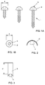
- figure 1a schematically represents a bone screw
- Figures 1a and 1b provide a side and top view of a metallic screw 1 as normally used in orthopaedic practice.
- the screw 1 contains a head 2 comprising a hole, in this embodiment a socket 3.
- the head 2 can however also comprise a groove or cross, or contain an extended part, such as a hexagonal extension.
- Figure 2 shows a stopper of the present invention, which stopper contains a hexagon 4 for engagement with socket 3, and a cap 5 that closely fits head 2.
- the stopper can be pushed-fixed in the socket, immediately after the screw has been screwed down in the bone.
- Figure 3 shows a preferred embodiment of the stopper of figure 2, wherein the cap 5 is an extended shank having length 1.
- the extended cap 5 can be conical, cylindrical or shaped in another form (e.g. hexagonal), as long as the the cap closely fits to the screw.
- the bone screw extension piece of the invention contains as means for detachably connecting the extension piece to the bone screw 1 a hexagon for engagement with a socket.
- AIBN ⁇ , ⁇ '-azo-bisisobutyronitrile
- the following time-temperature profile was then run: 0-60 min.: heat from 25 to 60°C; 60-240 min: temperature constant at 60°C; 240-300 min:heat to 90°C; 300-420 min: temperature constant at 90°C; 420-480 min: heat to 120°C; 480-540 min: temperature constant at 120°C; 540 min - approximately 12 h: cool to ambient temperature.
- the copolymer is obtained as a hard, glass-like, transparent material which closely resembles Plexi-glass in its appearance. The material is essentially free of residual monomers, as can be shown by NMR analysis. The material shows clearly X-ray fluoroscopic contras. The material is cut (sawn) into small pieces which are then used for the manufacture of the screw caps.
- Screw caps of different dimension can be obtained in known ways via this approach.
- the screw caps made out of the particular copolymer described in this example are hard in comparison to surrounding (muscular) tissues.
- a time-temperature profile such as the one described in Example 1 is then run.
- the material thus obtained is more rubbery (i.e. softer) than the material described in Example 1.
- This material is also essentially free of monomer. Machining into the desired screw caps is slightly more difficult, since the material is rubbery. Machining has to be performed while the material is cooled down, preferably through the use of liquid nitrogen. Screw caps of different shapes can be obtained in this way. The screw caps are softer, and show closer match with respect to the surrounding tissue.
Abstract
The present invention relates to a bone screw stopper,
comprising a shank that fits closely to the outer contour of
the head of the screw, and means for detachably connecting
the plug or stopper to the bone screw. Especially this
stopper comprises an extended shank whose section is at
least as large as the largest sectional part of the bone
screw, and the length of the extended shank is preferably
such that the end of the stopper remote from the bone screw
extends to the subcutis.
Description
The present invention relates to the field of screws
which are used in orthopaedic surgery. These screws are
referred to in this description and the attached claims as
"bone screws".
Bone screws are widely used as temporary medical
implants for the fixation of skeletal fractures and/or for
the fixation of orthopaedic implants. Important areas of
application are (i) fixation of the spinal cord after a
geometric correction, (ii) healing of fractures in the knee,
heel, elbow or hip, and (iii) fixation of hip prostheses.
Bone screws are generally made of a metallic material, e.g.
of titanium, cobalt-chrome alloys and stainless steel. The
metallic materials used should have an excellent
biocompatibility in contact with bone and surrounding
tissues.
As said, bone screws generally are temporary implants.
They play an important role in keeping the integrity of the
bone tissue after, e.g. a fracture.
The length of the screw used by the orthopaedic surgeon
is normally as short as possible. The shorter a screw is the
less discomfort is caused to the body, while the screw can
be screwed down or fixated more tightly.
In the course of the several months or years that the
screw stays in the body, bone growth leads to reinforced
bone structures. This makes the presence of the screw
superfluous, so that the screw is removed in a surgical
operation.
The removal of the fixation screws is normally
associated with several complications. The first problem is
associated with the fact that the bone screws used normally
comprise holes or grooves, such as sockets, for screwing
down, and/or comprise other irregularities, These holes and
so on, generally hexagonal in shape, which are normally
found on top of the screw, are filled and/or surrounded with
newly formed (bone) tissue. Obviously, this newly formed
tissue has to be removed prior to the introduction of the
screw driver. This removal of tissue is highly time-consuming
as it has to be performed with great care.
Moreover, the risk of infections increases with the
operation time.
Further, the screws cannot easily be located. Although
the screws are clearly visible under e.g. X-ray fluoroscopy,
the images obtained only provide a two-dimensional picture,
so that it is often difficult to find the exact position of
the screw.
The problem underlying the present invention is to
facilitate and accelerate the removal of bone screws in an
orthopaedic operation. This problem is solved by detachably
connecting a stopper, plug or cap to the bone screw after
the insertion thereof in the bone.
In a first aspect, the present invention relates to a
bone screw plug or stopper, comprising a shank that fits
close to the outer contour of the head of the screw, and
means for detachably connecting the plug or stopper to the
bone screw. This stopper can be seen as a cap that has a
smooth surface, which does not allow the ingrowth of bone
tissue. This cap should fit so closely to the outer contour
or perimeter of the bone screw head that substantially no
bone tissue can be formed between the cap and the screw.
In a preferred embodiment the bone screw stopper has an
extended shank, so that a bone screw extension piece is
formed. This stopper comprises an extended shank whose
section is at least as large as the largest sectional part
of the bone screw.
This embodiment, wherein the bone screw stopper when
attached to the bone screw extends from the bone, enables
the surgeon to remove the screw with as less damage to
tissues to the tissue as possible, whereas in current
practice a deep wound has to be made. In the most preferred
embodiment, the length of the extension piece is such that
the end of the extension piece remote from the bone screw
extends to the subcutis. In this embodiment , only a small
subcutaneous incision is needed to remove the screw.
Moreover, a skilled surgeon can locate the bone screw by
means of the stopper, without needing X-rays; he can trace
the stopper with his hands, if needed.
Although it is possible to shorten the stopper so that
it ends in the subcutis, e.g. by cutting or sawing the
superfluous part away, it is preferred to have available
stoppers of a variety of lengths, so that the surgeon can
choose therefrom after the bone screw has been applied.
Cutting and sawing leads to irregular surfaces, often with
sharp edges, which may lead to undesirable reactions, such
as tissue ingrowth and irritations, in the body.
Since smaller incisions are sufficient, and autologous
bone tissue does not have to be removed, the risk of
infections is reduced considerably when using the detachable
stopper of the invention.
The removal of the bone screws can hence be
accomplished as follows:
- after the formation of sufficient tissue to make the autologous bone tissue sufficiently strong, the location of the screw and/or the screw stopper is determined, e.g. by X-ray fluoroscopy;
- the end of the screw stopper is exposed via a small incision which in the most preferred embodiment only involves an incision in subcutaneous tissues;
- the screw stopper is pulled out, e.g. using a wrench, thus leaving an open channel;
- a screw driver is introduced through the channel and fixed to the screw;
- the screw is released and removed through the channel; and
- the wound is closed.
The bone screw stopper can be made of any material that
does not give undesirable reactions in the body. Such
materials should be biocompatible and inert to avoid any
complications when the screw stoppers are in the body.
Complications to be avoided are, e.g., infections,
irritation, cell death, tumor formation, and so on. Suitable
materials are known to the person skilled in the art, and
include ceramic materials, metals, alloys, or composite
materials. The manufacturing techniques are dependent on the
materials used. A major concern when using different
materials should be the biocompatibility. It is absolutely
mandatory, especially since the intended use of the screw
and screw caps in the body exceeds 30 days, that the
materials show excellent biocompatibility, i.e. any unwanted
effects, such as irritation, infection, tumor formation,
etc. that is brought about by the implant material is
untolerable.
Further, it is preferred if the material shows X-ray
visibility. This feature will render the bone screw stoppers
visible under routine X-ray fluoroscopy as is normally used
in operations to remove the bone screws. It enables the
surgeon to locate the position of the screw and the screw
stopper with high accuracy.
Preferred materials for the stoppers of the present
invention to be made of, are rubbery materials,
biocompatible, inert polymers. Such flexible materials more
or less match the surrounding tissue with respect to the
mechanical properties. If the screw cap is much stiffer than
the surrounding tissue, it may cause some discomfort to the
patent. The screw stopper are hence best manufactured out of
polymeric materials, particularly those of the methacrylate
family. These polymers which may be homopolymers,
copolymers, terpolymers or higher variants of polymers have
excellent biocompatibility, also in contact with bone.
The most optimal materials for the manufacture of the
new screw caps are methacrylate polymers that feature
intrinsic X-ray visibility, since they are built-up -either
completely or in part- from monomeric building blocks that
contain covalently bound iodine. Such polymeric materials
(homopolymers, copolymers, terpolymers, or higher variants)
are known in the art, and e.g. described in European
Application number 95303508.6. Inventor: K.W.M. Davy.
Applicant: The London Hospital Medical College, Turner
Street, Whitechapel, London E1 2AD (Great Britain), and
application number: PCT/NL95/00277. Inventor: L.H. Koole.
Applicant: Biomat B.V., Universiteitssingel 50, P.O. Box
616, 6200 MD Maastricht, The Netherlands).
It should be noted that a wide variety of copolymers,
homopolymers, terpolymers, and other materials can be
chosen. For example, ethylmethacrylate (see example 1) or
n-butylmethacrylate (see example 2) can be chosen as well as
other acrylates and methycrylates. Examples are, but are
limited to: 2-hydroxyethylmethacrylate, methylmethacrylate,
ethylacrylate, n-propylmethacrylate, methacrylamide,
N-vinylpyrollidone, styrene, ethylene, propylene, and other
molecules that contain one or more polymerizable double or
triple bonds.
Furthermore, other iodine-containing monomers can be
used to render the screw caps visible with X-ray
fluoroscopy. Such monomers are described in both patent
applications cited above.
In another embodiment, the screw stoppers are made of a
radiolucent polymer or a polymer made radiopaque through the
addition of a radiopaque additive, such as barium sulfate,
zirconium dioxide or other contrast fillers known in the
art.
The invention will be described in further detail,
while referring to the drawing. In the drawing, figure 1a
schematically represents a bone screw
Figures 1a and 1b provide a side and top view of a
metallic screw 1 as normally used in orthopaedic practice.
The screw 1 contains a head 2 comprising a hole, in this
embodiment a socket 3. The head 2 can however also comprise
a groove or cross, or contain an extended part, such as a
hexagonal extension.
Figure 2 shows a stopper of the present invention,
which stopper contains a hexagon 4 for engagement with
socket 3, and a cap 5 that closely fits head 2. The stopper
can be pushed-fixed in the socket, immediately after the
screw has been screwed down in the bone.
Figure 3 shows a preferred embodiment of the stopper of
figure 2, wherein the cap 5 is an extended shank having
length 1. The extended cap 5 can be conical, cylindrical or
shaped in another form (e.g. hexagonal), as long as the the
cap closely fits to the screw.
In a preferred embodiment, the bone screw extension
piece of the invention contains as means for detachably
connecting the extension piece to the bone screw 1 a hexagon
for engagement with a socket.
The invention will now be described in more detail,
while referring to the following examples.
Manufacture of screw caps out of a copolymer of
ethylmethacrylate and 2-[4'-iodobenzoyl] -ethyl methacrylate
(structure 1).

Ethylmethacrylate and compound 1 are mixed in a 4:1
(w:w) ratio, and transferred into a reaction vessel made out
of Teflon. Then, pure (sublimed) α,α'-azo-bisisobutyronitrile
(AIBN) was added in a 0.5% molar
concentration (i.e. mole of initiator: total moles of
monomer = 1:200). The reaction mixture is heated in a
thermostated oil bath, interfaced with a time-temperature
control system. The following time-temperature profile was
then run: 0-60 min.: heat from 25 to 60°C; 60-240 min:
temperature constant at 60°C; 240-300 min:heat to 90°C;
300-420 min: temperature constant at 90°C; 420-480 min: heat
to 120°C; 480-540 min: temperature constant at 120°C;
540 min - approximately 12 h: cool to ambient temperature.
The copolymer is obtained as a hard, glass-like, transparent
material which closely resembles Plexi-glass in its
appearance. The material is essentially free of residual
monomers, as can be shown by NMR analysis. The material
shows clearly X-ray fluoroscopic contras. The material is
cut (sawn) into small pieces which are then used for the
manufacture of the screw caps. For this, a computer-controlled
drill-freese is used. Screw caps of different
dimension (length of the stem, width, mushroom-like as shown
in Figure 2, formed as in Figure 2, etc.) can be obtained in
known ways via this approach. The screw caps made out of the
particular copolymer described in this example are hard in
comparison to surrounding (muscular) tissues.
Manufacture of screw caps out of a copolymer of n-butylmethacrylate
and 2-[4'-iodobensoyl]-ethyl methacrylate
(structure 2).
Butylmethacrylate andcompound 2 are mixed in a 4:1 (w:w)
ratio, and transferred into a reaction vessel made out of
Teflon. Then AIBN, a temperature-labile organic peroxide, or
another radical-generating species is added, preferably in a
0,5% molar concentration (i.e. mole of initiator:total moles
of monomer = 1:200). The reaction mixture is heated in a
thermostated oil bath, interfaced with a time-temperature
control system. A time-temperature profile such as the one
described in Example 1 is then run. The material thus
obtained is more rubbery (i.e. softer) than the material
described in Example 1. This material is also essentially
free of monomer. Machining into the desired screw caps is
slightly more difficult, since the material is rubbery.
Machining has to be performed while the material is cooled
down, preferably through the use of liquid nitrogen. Screw
caps of different shapes can be obtained in this way. The
screw caps are softer, and show closer match with respect to
the surrounding tissue.
Butylmethacrylate and
Claims (5)
- A bone screw stopper, comprising a shank that fits closely to the outer contour of the head of the screw, and means for detachably connecting the plug or stopper to the bone screw.
- A bone screw stopper according to claim 1, comprising an extended shank whose section is at least as large as the largest sectional part of the bone screw.
- A bone screw stopper according to claim 1 or 2, wherein the length of the extended shank is such that the end of the stopper remote from the bone screw extends to the subcutis.
- A bone screw stopper according to any one of claims 1-3, wherein said means for detachably connecting the stopper to the bone screw comprise a hexagon for engagement with a socket.
- A bone screw stopper according to any one of claims 1-4, consisting of a rubbery polymer, preferably of a methacrylate units containing polymer having intrinsic X-ray visibility.
Priority Applications (5)
| Application Number | Priority Date | Filing Date | Title |
|---|---|---|---|
| EP96202084A EP0820736A1 (en) | 1996-07-23 | 1996-07-23 | Detachably connecting cap for a screw used in orthopaedic surgery |
| US09/230,274 US6102914A (en) | 1996-07-23 | 1997-07-23 | Detachably connecting cap for a screw used in orthopaedic surgery |
| PCT/NL1997/000439 WO1998003209A1 (en) | 1996-07-23 | 1997-07-23 | Detachably connecting cap for a screw used in orthopaedic surgery |
| EP97930903A EP0918549A1 (en) | 1996-07-23 | 1997-07-23 | Detachably connecting cap for a screw used in orthopaedic surgery |
| AU34667/97A AU3466797A (en) | 1996-07-23 | 1997-07-23 | Detachably connecting cap for a screw used in orthopaedic surgery |
Applications Claiming Priority (1)
| Application Number | Priority Date | Filing Date | Title |
|---|---|---|---|
| EP96202084A EP0820736A1 (en) | 1996-07-23 | 1996-07-23 | Detachably connecting cap for a screw used in orthopaedic surgery |
Publications (1)
| Publication Number | Publication Date |
|---|---|
| EP0820736A1 true EP0820736A1 (en) | 1998-01-28 |
Family
ID=8224220
Family Applications (2)
| Application Number | Title | Priority Date | Filing Date |
|---|---|---|---|
| EP96202084A Withdrawn EP0820736A1 (en) | 1996-07-23 | 1996-07-23 | Detachably connecting cap for a screw used in orthopaedic surgery |
| EP97930903A Withdrawn EP0918549A1 (en) | 1996-07-23 | 1997-07-23 | Detachably connecting cap for a screw used in orthopaedic surgery |
Family Applications After (1)
| Application Number | Title | Priority Date | Filing Date |
|---|---|---|---|
| EP97930903A Withdrawn EP0918549A1 (en) | 1996-07-23 | 1997-07-23 | Detachably connecting cap for a screw used in orthopaedic surgery |
Country Status (4)
| Country | Link |
|---|---|
| US (1) | US6102914A (en) |
| EP (2) | EP0820736A1 (en) |
| AU (1) | AU3466797A (en) |
| WO (1) | WO1998003209A1 (en) |
Cited By (2)
| Publication number | Priority date | Publication date | Assignee | Title |
|---|---|---|---|---|
| US7720522B2 (en) | 2003-02-25 | 2010-05-18 | Medtronic, Inc. | Fiducial marker devices, tools, and methods |
| US7787934B2 (en) | 2002-07-29 | 2010-08-31 | Medtronic, Inc. | Fiducial marker devices, tools, and methods |
Families Citing this family (47)
| Publication number | Priority date | Publication date | Assignee | Title |
|---|---|---|---|---|
| US6511481B2 (en) | 2001-03-30 | 2003-01-28 | Triage Medical, Inc. | Method and apparatus for fixation of proximal femoral fractures |
| US6887243B2 (en) | 2001-03-30 | 2005-05-03 | Triage Medical, Inc. | Method and apparatus for bone fixation with secondary compression |
| US6793678B2 (en) | 2002-06-27 | 2004-09-21 | Depuy Acromed, Inc. | Prosthetic intervertebral motion disc having dampening |
| AU2003261286B2 (en) | 2002-07-19 | 2009-10-29 | Interventional Spine, Inc. | Method and apparatus for spinal fixation |
| US20040019265A1 (en) * | 2002-07-29 | 2004-01-29 | Mazzocchi Rudy A. | Fiducial marker devices, tools, and methods |
| US20040030237A1 (en) * | 2002-07-29 | 2004-02-12 | Lee David M. | Fiducial marker devices and methods |
| US7306603B2 (en) | 2002-08-21 | 2007-12-11 | Innovative Spinal Technologies | Device and method for percutaneous placement of lumbar pedicle screws and connecting rods |
| US20050216006A1 (en) * | 2004-03-23 | 2005-09-29 | Orbay Jorge L | Cap for cut metal orthopedic fastener |
| US7648523B2 (en) * | 2004-12-08 | 2010-01-19 | Interventional Spine, Inc. | Method and apparatus for spinal stabilization |
| US7857832B2 (en) | 2004-12-08 | 2010-12-28 | Interventional Spine, Inc. | Method and apparatus for spinal stabilization |
| US8105382B2 (en) | 2006-12-07 | 2012-01-31 | Interventional Spine, Inc. | Intervertebral implant |
| US8900307B2 (en) | 2007-06-26 | 2014-12-02 | DePuy Synthes Products, LLC | Highly lordosed fusion cage |
| US9247973B2 (en) | 2007-09-28 | 2016-02-02 | DePuy Synthes Products, Inc. | Anti-microbial implant |
| ES2435573T3 (en) | 2007-11-26 | 2013-12-20 | Biedermann Motech Gmbh & Co. Kg | Orthopedic heel nail |
| EP2471493A1 (en) | 2008-01-17 | 2012-07-04 | Synthes GmbH | An expandable intervertebral implant and associated method of manufacturing the same |
| BRPI0910325A8 (en) | 2008-04-05 | 2019-01-29 | Synthes Gmbh | expandable intervertebral implant |
| US9642658B2 (en) * | 2008-10-15 | 2017-05-09 | Orthoclip Llc | Device and method for delivery of therapeutic agents via internal implants |
| EP2346421A1 (en) * | 2008-10-15 | 2011-07-27 | Bioshape Solutions Inc. | Device and method for delivery of therapeutic agents via internal implants |
| US8388659B1 (en) | 2008-10-17 | 2013-03-05 | Theken Spine, Llc | Spondylolisthesis screw and instrument for implantation |
| US9526620B2 (en) | 2009-03-30 | 2016-12-27 | DePuy Synthes Products, Inc. | Zero profile spinal fusion cage |
| US20140163682A1 (en) * | 2012-12-11 | 2014-06-12 | Expandable Vertebral Implant | Expandable Vertebral Implant |
| US9393129B2 (en) | 2009-12-10 | 2016-07-19 | DePuy Synthes Products, Inc. | Bellows-like expandable interbody fusion cage |
| US9282979B2 (en) | 2010-06-24 | 2016-03-15 | DePuy Synthes Products, Inc. | Instruments and methods for non-parallel disc space preparation |
| US8979860B2 (en) | 2010-06-24 | 2015-03-17 | DePuy Synthes Products. LLC | Enhanced cage insertion device |
| EP2588034B1 (en) | 2010-06-29 | 2018-01-03 | Synthes GmbH | Distractible intervertebral implant |
| US9402732B2 (en) | 2010-10-11 | 2016-08-02 | DePuy Synthes Products, Inc. | Expandable interspinous process spacer implant |
| EP2758007A4 (en) * | 2011-09-21 | 2015-04-01 | Flexmedex Llc | Support device and method |
| US8940052B2 (en) | 2012-07-26 | 2015-01-27 | DePuy Synthes Products, LLC | Expandable implant |
| US20140067069A1 (en) | 2012-08-30 | 2014-03-06 | Interventional Spine, Inc. | Artificial disc |
| ES2578295T3 (en) * | 2012-11-14 | 2016-07-22 | Biedermann Technologies Gmbh & Co. Kg | Heel bone nail |
| US9522070B2 (en) | 2013-03-07 | 2016-12-20 | Interventional Spine, Inc. | Intervertebral implant |
| US9522028B2 (en) | 2013-07-03 | 2016-12-20 | Interventional Spine, Inc. | Method and apparatus for sacroiliac joint fixation |
| US11426290B2 (en) | 2015-03-06 | 2022-08-30 | DePuy Synthes Products, Inc. | Expandable intervertebral implant, system, kit and method |
| US9913727B2 (en) | 2015-07-02 | 2018-03-13 | Medos International Sarl | Expandable implant |
| US11596522B2 (en) | 2016-06-28 | 2023-03-07 | Eit Emerging Implant Technologies Gmbh | Expandable and angularly adjustable intervertebral cages with articulating joint |
| US11510788B2 (en) | 2016-06-28 | 2022-11-29 | Eit Emerging Implant Technologies Gmbh | Expandable, angularly adjustable intervertebral cages |
| US10537436B2 (en) | 2016-11-01 | 2020-01-21 | DePuy Synthes Products, Inc. | Curved expandable cage |
| US10888433B2 (en) | 2016-12-14 | 2021-01-12 | DePuy Synthes Products, Inc. | Intervertebral implant inserter and related methods |
| US10398563B2 (en) | 2017-05-08 | 2019-09-03 | Medos International Sarl | Expandable cage |
| US11344424B2 (en) | 2017-06-14 | 2022-05-31 | Medos International Sarl | Expandable intervertebral implant and related methods |
| US10940016B2 (en) | 2017-07-05 | 2021-03-09 | Medos International Sarl | Expandable intervertebral fusion cage |
| US11446156B2 (en) | 2018-10-25 | 2022-09-20 | Medos International Sarl | Expandable intervertebral implant, inserter instrument, and related methods |
| US11612451B2 (en) | 2020-02-06 | 2023-03-28 | Patrick C. Bell | Dental scanning methods for analyzing jaws |
| US11426286B2 (en) | 2020-03-06 | 2022-08-30 | Eit Emerging Implant Technologies Gmbh | Expandable intervertebral implant |
| US11744530B2 (en) | 2020-09-15 | 2023-09-05 | Patrick C. Bell | Radiographic dental jigs and associated methods |
| US11850160B2 (en) | 2021-03-26 | 2023-12-26 | Medos International Sarl | Expandable lordotic intervertebral fusion cage |
| US11752009B2 (en) | 2021-04-06 | 2023-09-12 | Medos International Sarl | Expandable intervertebral fusion cage |
Citations (4)
| Publication number | Priority date | Publication date | Assignee | Title |
|---|---|---|---|---|
| US3918440A (en) * | 1973-03-09 | 1975-11-11 | Werner Kraus | Device for promoting formation of bone material |
| DE2424176A1 (en) * | 1974-05-17 | 1975-11-20 | Anton Gerhard | DOWEL WITH SPREADING DEVICE AND COVER CAP |
| US5372503A (en) * | 1993-04-27 | 1994-12-13 | Dental Marketing Specialists, Inc. | Method for installation of a dental implant |
| RU2026648C1 (en) * | 1990-11-19 | 1995-01-20 | Сергеев Сергей Сергеевич | Device for osteosynthesis |
Family Cites Families (3)
| Publication number | Priority date | Publication date | Assignee | Title |
|---|---|---|---|---|
| US5730130A (en) * | 1993-02-12 | 1998-03-24 | Johnson & Johnson Professional, Inc. | Localization cap for fiducial markers |
| GB9410578D0 (en) * | 1994-05-26 | 1994-07-13 | London Hospital Med Coll | Novel (meth)acrylate monomers and denture base compositions prepared therefrom |
| DK0777503T3 (en) * | 1994-08-19 | 2000-03-20 | Biomat Bv | Radiopaque polymers and processes for their preparation |
-
1996
- 1996-07-23 EP EP96202084A patent/EP0820736A1/en not_active Withdrawn
-
1997
- 1997-07-23 AU AU34667/97A patent/AU3466797A/en not_active Abandoned
- 1997-07-23 US US09/230,274 patent/US6102914A/en not_active Expired - Fee Related
- 1997-07-23 EP EP97930903A patent/EP0918549A1/en not_active Withdrawn
- 1997-07-23 WO PCT/NL1997/000439 patent/WO1998003209A1/en not_active Application Discontinuation
Patent Citations (4)
| Publication number | Priority date | Publication date | Assignee | Title |
|---|---|---|---|---|
| US3918440A (en) * | 1973-03-09 | 1975-11-11 | Werner Kraus | Device for promoting formation of bone material |
| DE2424176A1 (en) * | 1974-05-17 | 1975-11-20 | Anton Gerhard | DOWEL WITH SPREADING DEVICE AND COVER CAP |
| RU2026648C1 (en) * | 1990-11-19 | 1995-01-20 | Сергеев Сергей Сергеевич | Device for osteosynthesis |
| US5372503A (en) * | 1993-04-27 | 1994-12-13 | Dental Marketing Specialists, Inc. | Method for installation of a dental implant |
Non-Patent Citations (1)
| Title |
|---|
| DATABASE WPI Derwent World Patents Index; AN 95-253164, XP002021387 * |
Cited By (5)
| Publication number | Priority date | Publication date | Assignee | Title |
|---|---|---|---|---|
| US7787934B2 (en) | 2002-07-29 | 2010-08-31 | Medtronic, Inc. | Fiducial marker devices, tools, and methods |
| US7720522B2 (en) | 2003-02-25 | 2010-05-18 | Medtronic, Inc. | Fiducial marker devices, tools, and methods |
| US8032204B2 (en) | 2003-02-25 | 2011-10-04 | Medtronic, Inc. | Fiducial marker devices, tools, and methods |
| US8073530B2 (en) | 2003-02-25 | 2011-12-06 | Medtronic, Inc. | Fiducial marker devices, tools, and methods |
| US8185184B2 (en) | 2003-02-25 | 2012-05-22 | Medtronic, Inc. | Fiducial marker devices, tools, and methods |
Also Published As
| Publication number | Publication date |
|---|---|
| EP0918549A1 (en) | 1999-06-02 |
| WO1998003209A1 (en) | 1998-01-29 |
| AU3466797A (en) | 1998-02-10 |
| US6102914A (en) | 2000-08-15 |
Similar Documents
| Publication | Publication Date | Title |
|---|---|---|
| EP0820736A1 (en) | Detachably connecting cap for a screw used in orthopaedic surgery | |
| Ramotowski et al. | Zespol: An Original Method of Stable Osteosynthesis. | |
| KR101089581B1 (en) | Surgical instrument | |
| US20170239061A1 (en) | Spinal implant configured for midline insertion and related instruments | |
| JPS58188442A (en) | Medical staple | |
| US20060293670A1 (en) | Surgical stabilization system | |
| US6749611B2 (en) | Bone screw, particularly for use with external fixators in fracture stabilization | |
| JP2006507085A (en) | Variable angle adaptive plate | |
| CA2268988A1 (en) | An apparatus and method for submergible, self-retaining distraction osteogenesis | |
| DE69413513T2 (en) | OSTIM APATIT PREPARATION FOR PROMOTING GROWTH IN BONE TISSUE | |
| EP3291752A1 (en) | Arthrodesis implant | |
| Luhr | Vitallium Luhr systems for reconstructive surgery of the facial skeleton | |
| CN109152690A (en) | Femur lifting device | |
| Prein et al. | Scientific and technical background | |
| ITRM20010123A1 (en) | INTERNAL BAND FIXER FOR FRACTURE AND BONE PROSTHESIS. | |
| JPH08112291A (en) | Screw fixing system | |
| Iizuka et al. | A new material (single crystal sapphire screw) for internal fixation of the mandibular ramus | |
| Sim et al. | The fixateur interne for stabilising fractures of the thoracolumbar and lumbar spine | |
| Fuente del Campo et al. | Fixation of horizontal maxillary osteotomies with biodegradable self-reinforced absorbable polylactide plates: preliminary results | |
| JPS62268553A (en) | Screw for fixing bone and hard tissue substitute material | |
| CN219070598U (en) | Degradable bone nail | |
| RU200324U1 (en) | INTROSEOUS STABILIZING BIOACTIVE IMPLANT FOR TUBULAR BONES | |
| RU47664U1 (en) | POLYMERIC OSTEOSYNTHESIS PIN WITH FOUR FLEXIBILITY | |
| Korovessis et al. | First experience with the use of compression cerclage Gundolf in orthopaedic and trauma surgery: a preliminary report | |
| RU2197912C2 (en) | Surgical and device method for treating spondylolisthesis |
Legal Events
| Date | Code | Title | Description |
|---|---|---|---|
| PUAI | Public reference made under article 153(3) epc to a published international application that has entered the european phase |
Free format text: ORIGINAL CODE: 0009012 |
|
| AK | Designated contracting states |
Kind code of ref document: A1 Designated state(s): AT BE CH DE DK ES FI FR GB GR IE IT LI LU MC NL PT SE |
|
| RBV | Designated contracting states (corrected) | ||
| STAA | Information on the status of an ep patent application or granted ep patent |
Free format text: STATUS: THE APPLICATION IS DEEMED TO BE WITHDRAWN |
|
| 18D | Application deemed to be withdrawn |
Effective date: 19980729 |