Cross-Reference to Related Applications
This patent application is a continuation-in-part of U.S. Patent Application Serial
No. 08/245,934 filed on May 19, 1994.
Field of the Invention
The subject invention relates to a device mountable on a hypodermic syringe or
other fluid delivery device which enables access to medication or injectable liquid in either
glass ampoules or in vials having elastomeric closures and the subsequent delivery of
medication or injectable liquid.
Background
A typical hypodermic syringe includes a syringe barrel with a mounting collar for
threadedly engaging the hub of a needle cannula. The hub and the needle cannula are
connected to one another or are maintained separately from the syringe barrel until shortly
prior to use. In cases where the needle is maintained separately, the medical practitioner
selects an appropriate needle assembly for the procedure being carried out. The needle
assembly is removed from its sterile package, and the hub of the needle assembly is
threadedly engaged with the mounting collar of the syringe barrel.
Liquid pharmaceuticals and other injectable liquids are often stored in rigid
containers which can be accessed using a hypodermic syringe. Some containers for liquid
pharmaceuticals are plastic or glass vials with an elastomeric closure that can be penetrated
by the needle of a hypodermic syringe. To access the liquid in a vial, the medical
practitioner moves the plunger of the hypodermic syringe in a proximal direction to draw
into the syringe barrel a volume of air substantially equal to the volume of medication that is
desired. The open distal end of the needle is then urged through the elastomeric closure of
the vial, and the air in the syringe barrel is injected into the vial. The distal tip of the needle
and the vial engaged therewith are then pointed gravitationally upwardly. The practitioner
ensures that the distal tip of the needle is covered by the medication in the vial by
manipulating the needle and the vial with respect to each other. The plunger of the
hypodermic syringe is then moved proximally to draw the medication through the needle
and into the chamber of the syringe barrel.
After withdrawing a desired dose of medication from a vial, the medical practitioner
may inject the medication into either a patient, another vial or into an injection site of an
intravenous set or catheter. There is a trend toward needleless I.V. systems which do not
require a pointed needle cannula to piece the injection site of an I.V. set. There are many
systems that have injection sites covered by a pre-slit septum which can be accessed by a
blunt cannula. Accordingly, after withdrawing medication from a vial using a sharp needle
the user must remove the needle and install a blunt cannula if the medication will be used
with an I.V. set. The user runs the risk of accidental needle stick using the needle to draw
the medication into the syringe and in the act of removing the needle to replace it with a
blunt cannula. Also, there is the potential of contaminating the components when they are
installed and removed during the filling and delivery process. Accordingly, there is a need
for a device which will allow filling of a syringe from a vial having a pierceable stopper
without the use of a very sharp needle and the subsequent delivery of the medication to an
I.V. set through a blunt cannula without having to handle or reshield sharp needles.
Plastic vials and elastomeric closures for vials are somewhat gas permeable. Some
pharmaceutical products will degrade rapidly in the presence of even small amounts of gas.
Hence, these pharmaceuticals typically are stored in glass ampoules. The frangible end of a
glass ampoule can be snapped off to enable access to the medication stored therein. The
medical practitioner may withdraw the medication by inserting the tip of the needle on a
hypodermic syringe into the medication stored in the ampoule. The plunger of the
hypodermic syringe is then moved proximally to draw the liquid medication in the ampoule
through the needle and into the barrel of the hypodermic syringe. The hypodermic syringe
may then be withdrawn from the ampoule and used in substantially the manner described
above. The ampoule typically is held with the open top gravitationally upwardly while the
hypodermic syringe is being filled. This needle length required for ampoule filling may
substantially exceed the length of the needle conveniently required for subsequent use for
injections. Likewise, the same or similar problems exist where the medication obtained
from an ampoule will be subsequently injected into an injection site having a pre-slit septum
since the needle must be installed and removed from the syringe and the new blunt cannula
installed. Thus, there are risks with accidental contamination and needle sticks before the
properly filled syringe and blunt cannula combination are prepared.
Summary of the Invention
The subject invention relates to a device for safety and efficiently filling a
hypodermic syringe. The device may include a blunt cannula having opposed proximal and
distal ends. The proximal end is configured for engagement with the distal end of the
hypodermic syringe. For example, the proximal end of the blunt cannula may include
projections for threadedly engaging a luer collar at the distal end of the syringe barrel. The
distal end of the cannula may be blunt and may be configured for selective mating with a
prior art fitting of an intravenous line.
The device further comprises a vial access spike which has opposed proximal and
distal ends and a communication passage extending axially therethrough. The proximal end
of the vial access spike is releasably mounted in fluid-tight engagement with the distal end
of the blunt cannula. For example, the proximal end of the passage through the vial access
spike may be frictionally secured in fluid-tight engagement over the distal end of a blunt
cannula. The distal end of the vial access spike defines a beveled tip that is sharp enough
to pierce the rubber stopper of a vial, but preferably not sharp enough to pierce skin
through incidental contact. The vial access spike may further include a cap for selective
sealing engagement over the proximal end of the spike. The cap may be unitarily
connected to the vial access spike by a hinge or a tether. A hinged connection may be
defined by an over-center hinge which is stable in a fully open or fully closed position of
the cap. However the over-center hinge will be biased at intermediate positions to urge the
cap into either the fully opened or fully closed position.
The device may further comprise a protective shield that can be mounted over at
least the distal end of the vial access spike. The protective shield may have a slot to
surround the hinge or tether. The shield prevents contamination of the beveled distal tip of
the spike prior to insertion into the vial.
The assembled blunt cannula, vial access spike and shield may be packaged
separately from the hypodermic syringe. Alternatively, the assembled blunt cannula and
vial access spike may be mounted on and packaged with the hypodermic syringe.
A hypodermic syringe that has the subject filling device mounted thereto may be
filled by removing the shield from the vial access spike and driving the beveled distal end of
the vial access spike through the vial stopper. The hypodermic syringe and the vial may
then be inverted, such that the liquid medication in the vial covers the distal end of the vial
access spike. The plunger of the hypodermic syringe may then be pulled in a proximal
direction to draw fluid into the syringe barrel. The user may then separate the connected
hypodermic syringe and blunt cannula from the vial access spike, and the connected
hypodermic syringe and blunt cannula may be used in the conventional manner. The vial
access spike will remain in the vial, and the cap can be engaged over the proximal end of
the spike to seal the vial for subsequent access.
A fluid transfer device for accessing fluid from vials and ampoules of the present
invention comprises a cannula assembly including a cannula having a proximal end, a distal
end and a lumen therethrough, and a hub having an open proximal end and a distal end
joined to the proximal end of the cannula so that the lumen is in fluid communication with
the open proximal end of the hub. A filling straw having a proximal end, a distal end, and a
passageway therethrough includes a housing at the proximal end, a needle portion at the
distal end and a shaft portion therebetween. A ledge between the needle portion and the
shaft portion is provided for limiting the depth of penetration of the needle portion into a
vial stopper. The housing includes a cavity in its proximal end in fluid communication with
the passageway. A cutting edge at the distal end of the needle portion is provided for
piercing a vial stopper. Structure is provided for removably engaging the cannula assembly
with the housing so that the open end of the hub is in fluid communication with the
passageway of the filling straw and the cannula is within the cavity. A shield having an
open proximal end, a distal end, and a sidewall therebetween defining a recess in the shield
is removably connected to the straw so that the shaft portion and the needle portion of the
straw are contained within the recess.
Another embodiment of the present invention includes a method for transferring
injectable liquid including the steps of:
Brief Description of the Drawings
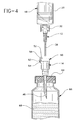
Fig. 1 is an exploded perspective view of the syringe filling device in accordance
with the subject invention for accessing medication in an ampule.
Fig. 2 is a side elevational view of the blunt cannula and vial access spike of the
subject invention.
Fig. 3 shows the filling device of Fig. 2 mounted to a hypodermic syringe and
accessing fluid medication in a stoppered vial.
Fig. 4 is a side elevational view similar to Fig. 3, but showing the hypodermic
syringe and blunt cannula separated from the vial and the vial access spike.
Fig. 5 is a side elevational view similar to Fig. 2, but showing an alternate vial
access spike.
Fig. 6 is a cross-sectional view of the blunt cannula and vial access spike of Fig. 5
taken along line 6-6.
Fig. 7 is a perspective view of the blunt cannula of the present invention and a
syringe aligned for assembly.
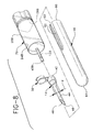
Fig. 8 is an alternative embodiment of the present invention wherein the blunt
cannula and the syringe barrel are integrally molded of one piece construction.
Figure 9 is a side elevational view of the fluid transfer device of the present
invention attached to a syringe.
Figure 10 is a partial cross-sectional view of a fluid transfer device and syringe of
Figure 9 taken along lines 10-10.
Figure 11 is a side elevational exploded view illustrating the assembly of the fluid
transfer device of the present invention.
Figure 12 is a cross-sectional view of the fluid transfer device of Figure 11 taken
along lines 12-12.
Figure 13 is a side elevational view of the fluid transfer device attached to a syringe
barrel illustrating the shield being removed.
Figure 14 is a side-elevational view illustrating the fluid transfer device and syringe
being used to withdraw injectable liquid from a vial having a pierceable stopper.
Figure 15 is a side elevational view of the fluid transfer device and syringe being
used to withdraw injectable liquid from an ampoule.
Figures 16 and 17 illustrate steps in a method of use of the present invention
between filling and dispensing of injectable liquid.
Figures 18-20 illustrate steps in another method of use of the present invention
between filling and dispensing of injectable liquid.
Figure 21 is a side elevational view of injectable liquid being delivered to an
injection site in an I.V. set using the cannula assembly of the present invention and a
syringe.
Figure 22 illustrates an alternative cannula assembly.
Figure 23 illustrates a standard hypodermic needle.
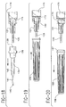
Figures 24 and 25 are side elevational views illustrating an alternative embodiment
of the present invention.
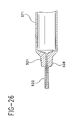
Figure 26 illustrates another embodiment of the present invention wherein the
cannula and the syringe barrel are integrally formed in one piece.
Figure 27 illustrates another embodiment of the fluid transfer device of the present
invention and a syringe.
Figure 28 is an exploded cross-sectional view of the fluid transfer device and
syringe of Figure 27 taken along lines 28-28.
Detailed Description
While this invention is satisfied by embodiments in many different forms, there are
shown in the drawings and will be herein described in detail preferred embodiments of the
invention with the understanding that the present disclosure is to be considered exemplary
of the principles of the invention and not intended to limit the scope of the invention to
those embodiments illustrated. The scope of the invention will be measured by the
appended claims and their equivalents.
The syringe filling device in accordance with the subject invention is identified
generally by the numeral 10 in Figs. 1 and 2. Filling device 10 includes a blunt cannula 12,
a vial access spike 14 and a shield 16. Filling device 10 is for use with a prior art
hypodermic syringe 18. Syringe 18 includes a syringe barrel 20 having a distal end 22, a
proximal end (not shown) and a fluid receiving chamber 24 therebetween. The proximal
end of syringe barrel 20 is open and slidably receives a plunger 26 in fluid-tight engagement
with the cylindrical wall defining chamber 24. Distal end 22 of syringe barrel 20 includes
an elongate tip 28 having a passage 30 extending axially therethrough and communicating
with chamber 24. The syringe preferably includes a luer collar 32 concentrically
surrounding tip 28 and includes an internal thread 34.
Blunt cannula 12 of syringe filling device 10 is preferably unitarily molded from a
thermoplastic material, and includes a proximal end 36, a distal end 38 and a lumen 40
extending axially therethrough. Proximal end 36 of blunt cannula 12 is configured for
threaded engagement with thread 34 of luer collar 32. Distal end 38 of blunt cannula 12 is
cylindrical and defines an external diameter "a". Distal end 38 also is configured for mating
with an intravenous fitting having a pre-slit septum to enable delivery of fluid medication
from chamber 24 of syringe barrel 20 to a patient.
Vial access spike 14 also is preferably unitarily molded from a thermoplastic
material, and includes a proximal end 42, a distal end 44 and a passage 46 extending axially
therethrough. Portions of passage 46 adjacent proximal end 42 are disposed in releasable
fluid-tight engagement over distal end 38 of blunt cannula 12a, shown in Fig. 2. Passage
46 is cylindrical and defines an internal diameter "b" adjacent proximal end 42 of vial
access spike 14 which is substantially equal to the external diameter of blunt cannula 12
adjacent distal end 38. Distal end 44 of vial access spike 14 includes a beveled tip 48
which is sufficiently sharp to be driven through the rubber stopper of a vial, as explained
and illustrated further herein. However, beveled tip 48 is preferably not sufficiently sharp
to penetrate skin upon incidental or accidental contact.
Vial access spike 14 further includes a cap 50 articulated to a hinge 52 which is
joined to spike 14 at a location near proximal end 42. Cap 50 is dimensioned to be
telescoped over proximal end 42 of vial access spike 14 for sealing substantially fluid-tight
engagement. As shown in Figs. 1-4, hinge 52 is an over center hinge with a first hinge 54
which defines an axis of rotation of cap 50. Over-center hinge 52 further includes a
second hinge element 56 which defines a rotational axis parallel to, but spaced from the
rotational axis of first hinge 54. Second hinge 56 is resiliently deflectable at elbow 57 and
is configured to be in an unbiased condition in the fully open position of cap 50, as shown
in Figs. 1-3, or in the fully closed position as shown in Fig. 4. However, second hinge
element 56 is biased at intermediate positions. The resiliency of second hinge element 56
therefore will assist any opening or closing forces exerted by a user and will urge cap 50
toward a fully opened or fully closed position.
Alternate hinge 52a, as shown in Fig. 5, defines a tether. The tether performs the
function of retaining cap 50 near proximal end 42 of spike 14. However, the tether does
not assist the opening or closing of cap 50.
Shield 16 is preferably formed from a thermoplastic material, and includes an open
proximal end 60 and a distal end 61 which preferably is closed. A passage 62 extends into
proximal end 60 and defines an inside diameter "c" which is substantially equal to outside
diameter "d" of vial access spike 14 adjacent proximal end 42 thereof. Thus, proximal end
60 of shield 16 can be removably frictionally engaged over the entire vial access spike to
prevent inadvertent contact with and contamination of vial access spike 14. Proximal end
60 of shield 16 is further characterized by a slot 63 which is dimensioned to surround
hinge 52, and to thereby permit full seating of shield 16 over vial access spike 14.
Filling device 10 may be packaged and sold in a pre-assembled condition as shown
in Fig. 2. More particularly, proximal end 42 of vial access spike 14 is frictionally engaged
over distal end 38 of blunt cannula 12, while shield 16 may be frictionally engaged over at
least portions of vial access spike 14. Alternatively filling device 10 and blunt cannula 12
may be packaged and sold in a premounted condition on hypodermic syringe 18. In this
latter embodiment, shield 16 preferably is dimensioned for releasable frictional engagement
over outer circumferential portions of luer collar 32. Also, vial access spike 14 and shield
16 may be sold assembled with the cap sealing the proximal end of the spike.
Filling device 10 is used with proximal end 36 of blunt cannula 12 threadedly
engaged to luer collar 32 of syringe barrel 20. Shield 16 is removed shortly prior to use.
Plunger 26 may then be moved proximally to draw into syringe barrel 24 a volume of air
approximately equal to the desired dose of medication. Beveled tip 48 of vial access spike
14 may then be driven through rubber stopper 64 of vial assembly 66. Plunger 26 is then
moved distally to urge the air from syringe chamber 24 into vial 66.
Hypodermic syringe 18 and vial 66 are inverted, as shown in Fig. 5, such that liquid
medication 68 covers the portion of passage 46 of vial access spike 14 adjacent distal tip
48 thereof. Plunger 26 is then moved again in a proximal direction to draw into chamber
24 the required dose of liquid medication 68. Syringe 18 and vial assembly 66 are then
inverted again such that vial assembly 66 is gravitationally below syringe 18. Syringe 18
and blunt cannula 12 then are separated from vial access spike 14 and vial 66. Syringe 18
and blunt cannula 12 may then be used in the standard manner as explained above. Vial
access spike 14 can remain in rubber stopper 64 of vial 66 to enable subsequent access to
medication 68. Medication 68 is sealed from the environment by rotating cap 58 about
hinge 52 and into sealing engagement with proximal end 42 of vial access spike 14.
Remaining medication 68 in vial 66 can be accessed subsequently by hingedly rotating cap
50 away from proximal end 42 of vial access spike 14. This subsequent access can be
achieved with a conventional prior art hypodermic syringe having a blunt cannula.
As best illustrated in Fig. 6 blunt cannula 12 and vial access spike 14 are preferably
connectable to each other by an interference frictional fit between the outside diameter of
the blunt cannula and the inside diameter of passageway 46 of the vial access spike. The
preferred blunt cannula is integrally molded of one piece of thermoplastic material.
However, the blunt cannula can be made with a plastic hub and a separate blunt cannula
made of a rigid material such as stainless steel joined to the hub by an adhesive or other
suitable means. Lumen 40 of the blunt cannula also includes frusto-conically shaped
proximal portion 41 suitable for frictionally engaging standard luer slip, as illustrated in Fig.
7, or locking luer-type syringes, as illustrated in Fig. 1.
Fig. 7 illustrates a blunt cannula 12 aligned for assembly to syringe 18A having
frusto-conically shaped elongate tip 28A which is adapted to frictionally and removably
engage the frusto-conically shaped portion 41 of the lumen of the blunt cannula. The blunt
cannula of the present invention is preferably capable of being used with locking luer type
syringes, such as syringe 18, and luer slip type syringes, such as syringe 18A.
Fig. 8 shows another embodiment of the present invention wherein syringe 70
includes integrally molded blunt cannula 12B having lumen 40B extending therethrough
and in fluid communication with chamber 24B of the syringe barrel. This embodiment of
the invention works substantially identically to the embodiments of Figs. 1-7 except that
the cylindrical blunt cannula cannot be separated from the syringe barrel.
While the invention has been described with respect to certain preferred
embodiments, it is apparent that various changes can be made without departing from the
scope of the invention as defined by the appended claims. For example, the blunt cannula
of the syringe filling device may be permanently mounted to a hypodermic syringe or
integrally molded as part of the syringe barrel. Additionally, the releasable engagement
between the vial access spike and the blunt cannula may take forms other than the frictional
engagement described and illustrated above. Still further, a metallic blunt needle cannula
may be used with the vial access spike.
Adverting to Figures 9-21, a fluid transfer device 120 for accessing fluid from vials
and ampoules comprises a cannula assembly 121 including a cannula 122 having a proximal
end 123, a distal end 125 and a lumen 127 therethrough. A hub 128 having an open
proximal end 129 and a distal end 131 is joined to proximal end 123 of the cannula so that
lumen 127 is in fluid communication with the open proximal end of the hub. Hub 128
preferably includes radial projection 132 for engaging the locking luer type collar of a
syringe barrel or other fluid delivery device, as will be explained in more detail hereinafter.
In this preferred embodiment, distal end 125 of the cannula includes a blunt tip 133, and
the cannula and the hub are integrally formed of a thermoplastic material. However, the
cannula and the hub can be separately formed and attached through various manufacturing
processes with adhesives such as epoxy being preferred.
A filling straw 134 includes a proximal end 135, a distal end 137, and a passageway
138 therethrough. Filling straw 134 includes a housing 139 at proximal end 134 and a
needle portion 141 at distal end 137 and a shaft portion 143 therebetween. The housing
includes a cavity 144 in its proximal end in fluid communication with passageway 138. The
distal end of needle portion 141 includes cutting edge 145 for piercing a vial stopper.
The cutting edge is preferably sharp enough to pierce a vial stopper but not as
sharp as a needle cannula used for human injection. A point or cutting edge which is sharp
enough for vial piercing and not sharp enough for human injection is evidenced in many
I.V. therapy devices such as spikes or cannula for use with vials having pierceable stoppers.
In this embodiment, needle portion 141 is made of metal such as stainless steel and can be
held to the shaft portion using various manufacturing methods with adhesives such as
epoxy being preferred. A metal needle portion offers the advantage of high strength and
small diameter to reduce penetration forces as the needle portion enters the vial stopper. It
is also within the purview of the instant invention to have the needle portion and the shaft
portion integrally formed of a single material such as thermoplastic. In either case, it is
preferred to have a shoulder 147 between the shaft portion and the needle portion to limit
the depth of penetration of the needle into a vial stopper. Also, the visual appearance of
the short needle portion, the pronounced shoulder and the relatively dull cutting edge
communicate to the user that this straw is not intended for injection and helps assure that
there will not be a mistaken attempt to use it for human injection.
The present invention includes means for releasably engaging the cannula assembly
with the housing so that the open proximal end of the hub is in fluid communication with
the passageway of the filling straw and the cannula is within the cavity or in the
passageway, as best illustrated in Figure 10. This connection should be relatively tight
since fluid will be drawn through the straw and the cannula assembly into a syringe or other
fluid delivery device. The means for removably engaging a cannula assembly to the
housing can be accomplished by numerous structure such as threads, complementary
projections and recesses and the like, with a frictional interference fit between interior
surface 149 of the housing and exterior surface 150 of the needle hub being preferred.
Accordingly, the housing and the hub can be releasably engaged and disengaged by moving
the housing and the hub toward each other or away from each other in an axial motion. As
will be explained in more detail hereinafter it is preferred that rotational force applied to the
straw, through the housing, can be transmitted to the hub for engaging and disengaging the
hub and a syringe barrel. This ability to transfer torque from the straw to the cannula
assembly can also be accomplished by the interference fit between interior surface 149 and
the housing and exterior surface 150 on the hub. However, additional structure can be
provided to facilitate the transfer of torque from the straw to the cannula assembly. In this
preferred embodiment, axial ribs 151 on the hub can engage axial ribs 152 in the housing to
transfer torque from the straw to the cannula assembly.
A shield 155 includes an open proximal end 157, a distal end 158 and a sidewall
159 therebetween defining a recess 161 and the shield. Shield 155 is removably connected
to filling straw 134 so that the needle portion and preferably the shaft portion of the straw
are within the recess.
Numerous structures can be used to achieve the removable connection between the
shield and the straw such as threads, projections and recesses to accomplish a snap-fit
arrangement, and interference fits. In this preferred embodiment, interior proximal surface
162 in the shield frictionally engaged exterior surface 163 on the housing. Accordingly,
axial force may be used to remove and re-install the shield on the straw. Interior surface
162 and exterior surface 163 are preferably frusto-conically shaped to provide smooth
frictional engagement. It is an important feature of this preferred embodiment that interior
proximal surface 162 of the shield also releasably engages exterior surface 150 on the hub
so that the shield can be used to shield the straw or, when the straw is removed, to shield
the cannula assembly. This is an important feature because it allows different methods for
using the fluid transfer device of the instant invention, depending on the preference of the
user.
The fluid transfer device of the present invention is suitable for use with fluid
delivery devices such as syringes. For the purpose of illustration, fluid transfer device 120
is connected to a hypodermic syringe 170 comprising a syringe barrel 171 having a distal
end 173, a proximal end 174 and a circular sidewall 175 defining a chamber 176 for
retaining fluid. Volume measuring indicia 172 are on the barrel for measuring the dose of
liquid to be delivered. The distal end of the syringe barrel is connected to hub 128 so that
the lumen of cannula 122 is in fluid communication with chamber 176 of the syringe barrel.
In this embodiment, distal end 173 of the syringe barrel includes a frusto-conically shaped
tip 177 having a conduit therethrough which provides a fluid path between the cannula and
the chamber. The frusto-conically shaped tip of the syringe barrel frictionally engages a
preferably frusto-conically-shaped surface 130 in open proximal end 129 of the hub. The
distal end of the syringe barrel also preferably, but not necessarily, includes a locking luer-type
collar 179 concentrically surrounding tip 177. The luer collar has an internal thread
180 which engages the radial projection 132 on hub 128 to hold it securely to the barrel. It
is within the scope of the present invention to include various hub configurations to attach
to a variety of other medical fluid handling devices. The hub configuration described
hereinabove, having a frusto-conically shaped interior cavity, reflects one of these many
possibilities. Many syringes and fluid handling devices, such as stopcocks and adapters,
and other fluid handling devices contain luer slip and locking luer type fittings to which a
hub having a frusto-conically shaped interior cavity will properly engage. It is within the
purview of the present invention to provide a fluid transfer device wherein the cannula
assembly is integrally molded with the syringe barrel.
A stopper 182 is positioned in chamber 176 in sliding fluid-tight engagement with
circular sidewall 175. A rigid elongate plunger rod 183 is connected to the stopper and
extends proximally through the open proximal end of barrel 171. The stopper and the
plunger rod can be made of one-piece unitary construction. Force applied to the plunger
rod causing sliding movement of the stopper in a proximal direction draws fluid through
conduit 178 into chamber 176. Conversely, sliding movement of stopper 182 in a distal
direction urges fluid from chamber 176 through conduit 178.
The fluid transfer device 120 of the present invention, coupled with a fluid delivery
device, such as a hypodermic syringe 170, can be used to access fluid in a vial or an
ampoule and deliver said fluid to the injection site of an I.V. set or catheter. As illustrated
in Figure 14, the fluid transfer device 120 can be used with syringe 170 to access injectable
liquid or medication, such as fluid 185, contained within a vial 186 having a pierceable
stopper 187. The fluid is accessed by piercing stopper 187 with needle portion 141 of
filling straw 134. Shoulder 147 between needle portion 141 and shaft portion 143 on the
filling straw will limit the penetration of the needle portion into the vial. In the preferred
embodiment the needle portion is approximately 10mm long and has a diameter of about
1.3mm. Initially, an volume of air approximately equal to the desired dosage is injected
into the vial. The vial is then inverted, as illustrated in Figure 14, and the fluid is
withdrawn into the syringe by action of the plunger in a proximal direction to urge fluid
185 from the vial 186 through passageway 138 of the filling straw, the lumen of the
cannula and into the chamber 176 of the syringe barrel. The user will compare the axial
position of the plunger with volume measuring indicia 172 on the cylindrical sidewall to
insure that the desired dose is obtained. It can be seen that the level of fluid 185 in the vial
will gradually decrease as fluid is drawn into the chamber of the syringe barrel. Shoulder
147 keeps the distal end of the needle portion close to the stopper to make it easy to
withdraw almost all of the liquid from the vial. Also, the short length of the needle portion
coupled with the shoulder and the larger shaft portion sends a clear message to the medical
practitioner that this device is not intended for injection into humans.
As best illustrated in Figure 15 the fluid transfer device of the present invention can
also be used to withdraw fluid 185 from ampoule 191. As noted above, at the time of use
the neck portion of the ampoule is snapped or severed leaving an open neck 192. Because
the ampoule does not have an elastomeric seal it is not inverted during the transfer of fluid
from the ampoule to a hypodermic syringe. Accordingly, a long filling straw, capable of
reaching toward the bottom or the sides of the ampoule is required. For this purpose, shaft
portion 143 of the filling straw is provided. The long shaft portion in conjunction with the
needle portion enables the fluid transfer device of the present invention to effectively
remove liquid from an ampoule. In the preferred embodiment the shaft portion is
approximately 15mm long and has an outside diameter of about 3mm. As with the vial,
fluid is withdrawn from the ampoule into the chamber of the syringe through action of the
plunger so that fluid is drawn through the passageway in the straw, the lumen of the
cannula assembly and into the chamber.
Referring to Figures 8-21, with particular emphasis on Figures 16-21, it can be seen
that there are two separate methods which can be used to deliver medication from the
syringe to the injection site through an I.V. set or other catheter device having an injection
site. The first method, as illustrated in Figures 16, 17 and 21. In this first method, after the
syringe is filled with fluid from a vial or ampoule or other source, shield 155 is placed over
filling straw 134 so that the shield is removably connected to the straw and needle portion
141 and shaft portion 143 are contained within recess 161 of the shield. This is the same
assembly as existed at the beginning of the filling process. In this preferred embodiment,
engagement between the shield and the straw is accomplished bv axial motion which causes
structure on the open proximal end of the shield to engage the housing on the filling straw.
The filled syringe is then delivered to the point of use. At the point of use, the user will
remove the assembly of the shield and straw from the cannula assembly by grasping the
straw, preferably at raised portion 136 on the straw, and applying an axial force to remove
the straw from the cannula assembly, as illustrated in Figure 17. Since the cannula
assembly is attached to the syringe through the locking luer collar, the connection between
the cannula assembly and the syringe barrel is stronger than the frictional engagement
between the filling straw and the cannula assembly, so that the actual force applied will not
remove the cannula assembly from the syringe. Depending on the structures of the various
parts, the forces can be balanced so that the desired result is obtained with respect to
removing components. The syringe is now ready for delivering medication, as will be
described hereinafter in more detail.
The second method for using the fluid transfer device of the present invention, as
best illustrated in Figures 18-21, requires the user to remove filling straw 134 immediately
after the syringe is filled with fluid from a vial or ampoule by grasping the filling straw,
preferably by enlarged portion 136, and applying an axial distal force to the straw to
remove it from the cannula assembly. Shield 155 is then placed over the cannula assembly,
as illustrated in Figure 19 to protect the cannula until the time of use. The second method
is possible because hub 128 of the cannula assembly and housing 139 of the filing straw
have similar exterior shapes so that shield 155 can engage either the hub or the housing. In
this preferred embodiment the engagement is frictional and engagement and disengagement
can be accomplished by applying axial forces. At the time of use, as illustrated in Figure 20
shield 155 is removed from the cannula assembly by applying a distal axial force.
The preferred embodiment of the fluid transfer device of the present invention
includes a cannula having a blunt distal end for use with I.V. sets or other catheter devices
having injection sites with pre-slit septums. Specifically. as illustrated in Figure 21, an I.V.
set 195 can include a housing 197 having a hollow interior conduit 198 and a flexible tube
199 connected to the vascular system of the patient, usually through a catheter. Housing
197 also contains flexible tube 196 which is connected to a source of I.V. fluid. Housing
197 also includes port 200 having a conduit 201 therethrough in communication with the
hollow interior. A septum 203 covers the end of the conduit or as positioned within the
conduit. The most common ports are covered by pierceable septums or pre-slit septums
and are known in the art and sometimes referred to as "PRN" from the Latin pro re nata
meaning "as the need arises." The septum is preferably made of rubber or another
elastomeric material which permits insertion of a sharp needle cannula in order to infuse
fluids into or to withdraw fluids from the catheter Upon withdrawal of the needle cannula,
the septum seals itself. As illustrated in Figure 21, septum 203 is a pre-slit septum having a
slit 204 therein. Septum 203 effectively seals conduit 201 from the exterior of the housing.
However, access to the conduit can be achieved by pressing blunt tip 133 of cannula 122
against the area of the septum containing slit 204. Gentle force applied to the syringe
assembly in an axial direction will cause the blunt distal end of the cannula to enter the
conduit through the slit which is forced open by the blunt cannula. Upon removal of the
blunt cannula from the conduit, the slit portion of the septum automatically seals itself.
Since housing 197 is connected to the patient's vascular system medication can be given to
the patient through the PRN port without additionally piercing the patient's vein or, in this
case, without the use of a sharp needle.
It is an important feature of the present invention that the entire process of filling
the syringe from a vial or ampoule with a fluid, such as an injectable liquid or medication,
and the delivery of this fluid to the patient can be accomplished by using the cannula
assembly of the present invention alone and without the use of any injection needles. The
most common prior art way to withdraw medication from a vial with a pierceable septum is
to attach a standard hypodermic needle assembly, illustrated in Figure 23, to a hypodermic
syringe. The fluid is drawn into the syringe barrel and then the needle is discarded and a
blunt cannula is attached to the syringe. This additional step creates an opportunity to an
accidental needle stick and requires the presence of some form of disposal system.
Wherein the present invention, in its preferred embodiment, does not use a standard needle
and does not require a disposal step since all of the components of the fluid transfer device
can stay with the syringe until the time of use, at which time, all components are suitably
disposed of. Also, the present invention provides a fluid transfer device which allows for
filling a syringe and delivering the medication to the patient without the use of a sharp
injection cannula.
Figure 22 illustrates an alternative cannula assembly 221 including a metal cannula
222, preferably made of stainless steel. Cannula 222 includes a proximal end 223, distal
end 225 having a lumen therethrough. Distal end 225 also includes blunt tip 233. Cannula
assembly 221 functions substantially as cannula assembly 121 except that the cannula is
made of metal . Stainless steel cannula are desirable because of their great strength
advantage over thermoplastic cannula which allows such cannula to be made in smaller
outside diameters and a large lumen diameter while still having substantial strength.
Figure 23 illustrates a prior art needle assembly 321 which is commonly used to
inject medication into a patient and for transferring fluid through pierceable septums such
as septums found in a medication vials and I.V. sets. Needle assembly 321 includes needle
cannula 322 having a proximal end 323, a distal end 325 and a lumen therethrough. Distal
end 25 further includes a sharp point 333 capable of easily piercing skin and flexible
stoppers.
The preferred embodiment of the fluid transfer device of the present invention
includes a cannula assembly having a blunt cannula for use which allows the use of one
device for filling a syringe through a vial or ampoule and delivering the fluid from the vial
or ampoule through a pre-slit septum of an I.V. set or other catheter device. Accordingly,
the preferred embodiment is a needleless system for filling and delivering injectable fluid
which does not require a sharpened needle cannula or an additional step of disposing of
such cannula after the syringe is filled. However, it is within the purview of the present
invention to include a fluid transfer device which contains a needle assembly having a
needle cannula with a sharpened distal tip such as needle assembly 321. In usages where a
pre-slit septum is not available in the catheter or I.V. set, a sharpened steel needle cannula
must be used. However, even with a needle assembly having a sharpened needle cannula,
the fluid transfer device of the present invention offers a clear advantage over the prior art
in that the needle assembly stays with the syringe from the time of filling through the time
of injection and there is no additional step of removing a sharpened needle cannula from
the syringe after filling the syringe and no additional complications regarding the disposal
of the sharpened needle cannula in this intermediate step. Also the needle cannula is
protected from damage during the filling procedure.
Figures 24 and 25 illustrate an alternative fluid transfer device of the present
invention. The fluid transfer device of Figures 24 and 25 functions substantially the same
way as the fluid transfer device of Figures 9-20 except that structure is provided so that the
removal of the filling straw from the cannula assembly requires a rotational motion.
Specifically, alternative fluid transfer device 420 includes a cannula assembly 421 having a
cannula 422 and a hub 428. Hub 428 further includes a locking luer collar 424 having an
internal thread 426. Filling straw 434 includes a housing 439 having a radial projection
440 configured to engage internal thread 426 of luer collar 424. Accordingly, attachment
of the filling straw to the cannula assembly is accomplished by a rotational motion. A
shield 455 is removably connected to the straw. The straw and the shield are configured so
that the shield can be removed and reconnected to the straw through axial motion of the
shield with respect to the straw. This alternative embodiment of the present invention
offers a distinct advantage to the user since the shield is removable from the straw through
axial motion and the straw is removable from the cannula assembly through rotational
motion further assuring that the user will not accidentally remove one component when he
or she intends to remove another.
Figure 26 illustrates an alternative structure of the fluid transfer device of the
present invention wherein the cannula or the cannula assembly is integrally formed with a
syringe barrel. Specifically, cannula assembly 521 which includes cannula 522 and hub 528
is integrally molded with syringe barrel 571 so that the cannula is not removable from the
syringe barrel. Other than this feature the syringe and blunt cannula function substantially
the same way as the embodiment illustrated in Figures 9-21.
Figures 27-28 illustrate an alternative fluid transfer device 600. This fluid transfer
device 600 is intended for use in applications where a separate cannula assembly is not
required. Fluid transfer device 600 includes a filling straw 634 having a proximal end 635,
a distal end 637 and a passageway 638 therethrough. The straw includes a housing 639 at
said proximal end, a needle portion 641 at said distal end, and a shaft portion 643
therebetween. The needle portion and the shaft portion are preferably integrally molded of
thermoplastic material. The housing includes a preferably frusto-conically shaped cavity
644 in its proximal end in fluid communication with passageway 638. A cutting edge 645
at the distal end of the needle portion is provided for piercing a vial stopper. A shield 655
having an open proximal end 657, a distal end 658 and a sidewall 659 therebetween
defining a recess 661 in the shield. The shield is removably connected to the straw so that
the shaft portion and the needle portion of the straw are preferably contained within the
recess. A syringe 670 having an elongate cylindrical body 671 defining a chamber 676 for
retaining fluid, an open proximal end, a distal end 673 and a frusto-conically shaped tip
677, extending from the distal end and having a tip passageway 678 therethrough in fluid
communication with the chamber. The tip is positioned within cavity 644 of housing 639
so that chamber 676 is in fluid communication with passageway 638 of the filling straw.
Cavity 644 in the housing includes a frusto-conically shaped wall 646 configured to
frictionally engage the frusto-conically shaped tip on the syringe barrel. There are
needleless systems comprising valves and special fittings which are designed to accept the
standard frusto-conically shaped tip of a hypodermic syringe barrel. With these systems a
separate cannula assembly is not necessary since the tip portion of the syringe barrel acts as
the cannula in the system. In all other respects the embodiment of Figures 27 and 28
function substantially the same as the embodiment of Figures 9-20 with the exception that
the fluid is delivered through the tip of the syringe into the fluid receiving device which
could even be a pre-slit septum designed to accept a standard syringe tip.
In this embodiment, it is preferred but not necessary that the syringe include a
locking luer-type collar 679 having an internal thread 680. The proximal end of housing
639 includes radial projection 632 which is adapted to engage thread 680 to further
enhance the connection between the housing and the syringe barrel In this embodiment, it
is preferable that shield 655 includes a radial projection 640 so that the shield can engage
the luer collar when the filling straw is removed, so that after filling the syringe the straw
may be discarded and the syringe tip reshielded with shield 655 for delivery to the point of
use. In the alternative, the filled syringe with shielded straw attached may be taken to the
point of use wherein the shield and the straw are removed together and discarded as
described hereinabove in using the embodiments of Figures 9-20.