EP0822430A2 - Waveguide optical deflector, process for producing the same, and saw blade for use in this process - Google Patents
Waveguide optical deflector, process for producing the same, and saw blade for use in this process Download PDFInfo
- Publication number
- EP0822430A2 EP0822430A2 EP97113008A EP97113008A EP0822430A2 EP 0822430 A2 EP0822430 A2 EP 0822430A2 EP 97113008 A EP97113008 A EP 97113008A EP 97113008 A EP97113008 A EP 97113008A EP 0822430 A2 EP0822430 A2 EP 0822430A2
- Authority
- EP
- European Patent Office
- Prior art keywords
- optical
- face
- optical waveguide
- oblique end
- core
- Prior art date
- Legal status (The legal status is an assumption and is not a legal conclusion. Google has not performed a legal analysis and makes no representation as to the accuracy of the status listed.)
- Granted
Links
Images


Classifications
-
- G—PHYSICS
- G02—OPTICS
- G02B—OPTICAL ELEMENTS, SYSTEMS OR APPARATUS
- G02B6/00—Light guides; Structural details of arrangements comprising light guides and other optical elements, e.g. couplings
- G02B6/24—Coupling light guides
- G02B6/42—Coupling light guides with opto-electronic elements
-
- G—PHYSICS
- G02—OPTICS
- G02B—OPTICAL ELEMENTS, SYSTEMS OR APPARATUS
- G02B6/00—Light guides; Structural details of arrangements comprising light guides and other optical elements, e.g. couplings
- G02B6/24—Coupling light guides
- G02B6/42—Coupling light guides with opto-electronic elements
- G02B6/4201—Packages, e.g. shape, construction, internal or external details
- G02B6/4204—Packages, e.g. shape, construction, internal or external details the coupling comprising intermediate optical elements, e.g. lenses, holograms
- G02B6/4214—Packages, e.g. shape, construction, internal or external details the coupling comprising intermediate optical elements, e.g. lenses, holograms the intermediate optical element having redirecting reflective means, e.g. mirrors, prisms for deflecting the radiation from horizontal to down- or upward direction toward a device
-
- B—PERFORMING OPERATIONS; TRANSPORTING
- B28—WORKING CEMENT, CLAY, OR STONE
- B28D—WORKING STONE OR STONE-LIKE MATERIALS
- B28D5/00—Fine working of gems, jewels, crystals, e.g. of semiconductor material; apparatus or devices therefor
- B28D5/02—Fine working of gems, jewels, crystals, e.g. of semiconductor material; apparatus or devices therefor by rotary tools, e.g. drills
-
- G—PHYSICS
- G02—OPTICS
- G02B—OPTICAL ELEMENTS, SYSTEMS OR APPARATUS
- G02B6/00—Light guides; Structural details of arrangements comprising light guides and other optical elements, e.g. couplings
- G02B6/10—Light guides; Structural details of arrangements comprising light guides and other optical elements, e.g. couplings of the optical waveguide type
- G02B6/12—Light guides; Structural details of arrangements comprising light guides and other optical elements, e.g. couplings of the optical waveguide type of the integrated circuit kind
- G02B6/122—Basic optical elements, e.g. light-guiding paths
- G02B6/1221—Basic optical elements, e.g. light-guiding paths made from organic materials
-
- G—PHYSICS
- G02—OPTICS
- G02B—OPTICAL ELEMENTS, SYSTEMS OR APPARATUS
- G02B6/00—Light guides; Structural details of arrangements comprising light guides and other optical elements, e.g. couplings
- G02B6/10—Light guides; Structural details of arrangements comprising light guides and other optical elements, e.g. couplings of the optical waveguide type
- G02B6/12—Light guides; Structural details of arrangements comprising light guides and other optical elements, e.g. couplings of the optical waveguide type of the integrated circuit kind
- G02B2006/12083—Constructional arrangements
- G02B2006/12104—Mirror; Reflectors or the like
Definitions
- the present invention relates to an optical deflector comprising an optical waveguide having a deflection mechanism for use in optical communication, measurement, information processing, etc., and a process for producing the same.
- Optical waveguides having such a deflection mechanism include a planar optical waveguide and a fiber optical waveguide.
- optical waveguide When the term “optical waveguide” is simply mentioned in the following description of the present invention, it is intended to encompass both of a planar optical waveguide and a fiber optical waveguide . In other cases where specific mention is necessary, one type is referred to as a "planar optical waveguide”, while other type is referred to as a “fiber optical waveguide "or an "optical fiber.”
- a 45-degree oblique end face mirror formed by providing a planar optical waveguide or a fiber optical waveguide with a 45-degree oblique end face, is capable of compact 90-degree deflection. Accordingly, an optical deflector comprising a planar optical waveguide provided with the above-mentioned mirror and an optical deflector comprising a fiber optical waveguide provided with the above-mentioned mirror are expected to be elements effective, for example, in providing a high level of integration of an optical module and reducing the assembling cost.
- optical transmitter and receiver with a structure wherein arrayed surface emitting (surface sensitive) optical devices are coupled with optical waveguides disposed in horizontal directions relative to the emitting (sensitive) surface of these surface emitting (sensitive) optical devices by means of 45-degree oblique end face mirrors formed at ends of the optical waveguides in order to produce compact and inexpensive parallel optical transmitter and receiver.
- surface sensitive optical devices are coupled with optical waveguides disposed in horizontal directions relative to the emitting (sensitive) surface of these surface emitting (sensitive) optical devices by means of 45-degree oblique end face mirrors formed at ends of the optical waveguides in order to produce compact and inexpensive parallel optical transmitter and receiver.
- Reported technologies of forming a 45-degree oblique end face mirror at an end of a planar optical waveguide include (1) a method wherein an end portion thereof is mechanically cut off obliquely with a microtome (see B. L. Booth, "Polymers for integrated optical waveguides," in Polymers for Electronic and Photonic Applications, C. P. Wong, Ed., New York: Academic, 1993, pp. 549-599), (2) a method wherein such an oblique end face mirror is formed by reactive ion etching [see H. Takahara et al, Proc. of SPIE, vol.
- Figs. 1 and 2 are diagrams illustrating the method (1) wherein an end portion of a planar optical waveguide is mechanically cut off obliquely with a microtome.
- numeral 201 refers to a waveguide film, 202 to a blade, 203 to waveguide films having respective oblique end face mirrors formed at the ends thereof by cutting-off with the blade 202.
- the waveguide film 201 fixed oblique by 45 degrees relative to the cut-off direction is cut off with the blade 202 to form oblique micro-mirrors (face mirrors).
- This method (1) is simple but involves problems such as (1-i) an inapplicability thereof to an optical waveguide formed from a rigid material such as glass and to an optical waveguide supported on a rigid substrate such as a silicon or glass substrate, (1-ii) an incapability of forming oblique end face mirrors only for some of optical waveguides formed in parallel with each other in one and the same sample, though possible for all of the optical waveguides, (1-iii) a difficulty in highly accurately positioning a location where an oblique end face mirror is formed, and (1-iv) a slight increase in reflection loss because of a limited smoothness of cut-off surfaces.
- the method (2) wherein an oblique end face mirror is formed by reactive ion etching involves problems such as (2-i) a complicated and time-consuming step, (2-ii) a difficulty in determining etching conditions and a difficulty in forming an oblique end face mirror with a good accuracy of the angle of inclination thereof.
- the laser abrasion method (3) involves problems such as (3-i) expensive equipment and time-consuming mirror formation, and (3-ii) a difficulty in determining etching conditions and a necessity of great alterations in mirror formation equipment and conditions for every material.
- Figs. 3 and 4 are diagrams illustrating the method (4) wherein a 45-degree cut in a planar optical waveguide is made with a rotary blade to form oblique end face mirrors.
- numeral 204 refers to a substrate, 205 to a lower cladding layer, 206 to a core, 207 to an upper cladding layer, 208 to a rotary blade, and 209 to a 45-degree cut.
- a sample is fixed to have the optical axis of the planar optical waveguide at an angle of 45 degrees with the rotary blade, and then cut with the rotary blade 208 at an angle of 45 degrees to form the 45-degree cut 209 in a waveguide consisting of a core and a cladding.
- This method (4) though advantageous in that a mirror plane excellent in smoothness can be formed by selecting a suitable blade, involves problems such as, (4-i) such a difficulty in fixing a sample as to require specially devised equipment, (4-ii) a difficulty in controlling the angle, and (4-iii) a difficulty in smoothing the oblique end faces by secondary working or processing because the oblique end faces are formed in a narrow cut groove.
- This method though widely used due to its capability of obtaining a smooth optical mirror plane, involves problems such as (5-i) a difficulty in securing an accuracy of a position where an oblique end face mirror is formed, (5-ii) a difficulty in delicately controlling the angle of inclination of a mirror plane, (5-iii) a difficulty in polishing a number of samples at once and a low productivity because of the necessity of a long polishing time, and (5-iv) a methodological incapability of localized mirror formation midway of optical paths of a fiber sheet or a fiber board having optical fibers embedded in the sheet or board with a resin.
- an oscillation wavelength is in a 0.85 ⁇ m band.
- a waveguide material involves a low loss in this wavelength band.
- a polyimide known as a heat-resistant polymeric material involves an electron transition absorption ranging from the ultraviolet region to the visible light region with a high loss of about 1dB/cm in the 0.85 ⁇ m band.
- an optical waveguide made of a conventional material is unsuitable for use as an optical waveguide constituting an optical deflector.
- the method (1) wherein oblique end face mirrors are formed by a cutting-off operation involves problems such as (1-i) an inapplicability thereof to an optical waveguide formed using a rigid material or supported on a rigid substrate, (1-ii) an incapability of forming oblique end face mirrors only for some of optical waveguides formed in parallel with each other in one and the same sample, (1-iii) a difficulty in securing an accuracy of a position where oblique end face mirrors are formed, and (1-iv) a slightly high reflection loss attributed to the roughness of cut-off surfaces.
- the method (2) wherein an oblique end face mirror is formed by reactive ion etching involves problems such as (2-i) a complicated and time-consuming step, (2-ii) a difficulty in determining conditions and a difficulty in putting the angle of inclination of an oblique end face mirror in accurate agreement with the desired angle.
- the laser abrasion method (3) involves problems such as (3-i) expensive equipment and time-consuming mirror formation, and (3-ii) a difficulty in determining etching conditions and a necessity of great alterations in mirror formation equipment and conditions for every material.
- the method (4) wherein a 45-degree cut in a planar optical waveguide is made with a rotary blade to form oblique end face mirrors involves problems such as, (4-i) such a difficulty in fixing a sample as to require specially devised equipment, (4-ii) a difficulty in controlling the angle, and (4-iii) a difficulty in smoothing the oblique end faces by secondary working or processing because the oblique end faces are formed in a narrow cut groove.
- an oblique end face mirror is formed by oblique polishing, but the oblique polishing method (5) involves problems such as (5-i) a difficulty in securing an accuracy of a position where an oblique end face mirror is formed, (5-ii) a difficulty in delicately controlling the angle of inclination of a mirror plane, (5-iii) a difficulty in polishing a number of samples at once and a low productivity because of the necessity of a long polishing time, and (5-iv) a methodological incapability of localized mirror formation midway of optical paths of a fiber sheet or a fiber board having optical fibers embedded in the sheet or board with a resin.
- problems such as (5-i) a difficulty in securing an accuracy of a position where an oblique end face mirror is formed, (5-ii) a difficulty in delicately controlling the angle of inclination of a mirror plane, (5-iii) a difficulty in polishing a number of samples at once and a low productivity because of
- An object of the present invention that has been made in view of the foregoing circumstances is to provide a process for simply and accurately forming an oblique end face (micro-mirror) with a desired angle of inclination at a desired position of a planar optical waveguide or an optical fiber constituting an optical element, and an optical deflector having a peculiar form resulting from the above-mentioned process and a capability of securing function and effect, which cannot be secured by conventional optical deflectors, due to that form.
- Another object of the present invention is to provide an optical deflector formed using a material involving a small propagation loss in a 0.85 ⁇ m band, a 1.3 ⁇ m band and a 1.55 ⁇ m band for use in the fields of optical interconnection and optical communication.
- a further object of the present invention is to provide a working tool necessary for producing a suitable optical deflector.
- the present invention provides an optical deflector comprising an optical waveguide provided with a deflective oblique end face having a desired angle of inclination, and having a function of deflecting an optical path of light propagated through the optical waveguide to give rise to emergence of the light out of the plane of the optical waveguide or deflecting an optical path of light incident upon the optical waveguide out of the plane of the optical waveguide to effect optical coupling thereof with the optical waveguide, while utilizing reflection on the oblique end face; characterized:
- the angle of inclination of the plane of incidence or emergence relative to a plane perpendicular to the optical axis of the optical waveguide may be 1 degree to 30 degrees.
- the V-shaped groove may be filled with a substance having a refractive index close to that of the core material of the optical waveguide. This substance may be a resin.
- the present invention also provides another optical deflector comprising an optical waveguide provided with a deflective oblique end face having a desired angle of inclination, and having a function of deflecting an optical path of light propagated through the optical waveguide to give rise to emergence of the light out of the plane of the optical waveguide or deflecting an optical path of light incident upon the optical waveguide out of the plane of the optical waveguide to effect optical coupling thereof with the optical waveguide, while utilizing reflection on the oblique end face; characterized:
- the substance having a refractive index close to that of the core material of the optical waveguide may be a resin.
- the optical waveguide may be either a planar optical waveguide or an optical fiber.
- the core and cladding of the optical waveguide may be made of respective glass materials.
- the core of the optical waveguide may be made of a glass material, while the cladding thereof may be made of a polymeric material.
- the core and claddings of the optical waveguide may be made of respective polymeric materials.
- the polymeric materials that may constitute the above-mentioned core and cladding may be respective polymers represented by the following structural formula (I), provided that the polymeric material of the cladding has a refractive index lower than that of the polymeric material of the core.
- the polymeric materials that may constitute the aforementioned core and cladding may be respective epoxy resins each obtained by photo-setting one member selected from the group consisting of substances each represented by any one of the following structural formulae (II) to(IV), and mixtures thereof, provided that the polymeric material of the cladding has a refractive index lower than that of the polymeric material of the core.
- Z is M is or n is 0 or an arbitrary natural number.
- Y is or (wherein X is or ⁇ CH 2 ⁇ ).
- the polymeric materials that may constitute the aforementioned core and cladding may be respective polymers selected from the group consisting of polysiloxanes having recurring units represented by the following structural formula (V) or (VI), copolymerized polysiloxanes having recurring units represented by the same structural formula (V) or (VI), and mixtures thereof, provided that the polymeric material of the cladding has a refractive index lower than that of the polymeric material of the core.
- R 1 and R 2 which may be the same as or different from each other, are each an alkyl, deuterated alkyl or halogenated alkyl group represented by C n Y 2n+1 (wherein Y stands for hydrogen, deuterium, or a halogen; and n stands for an integer of at most 5), or a phenyl, deuterated phenyl or halogenated phenyl group represented by C 6 Y 5 (wherein Y stands for hydrogen, deuterium, or a halogen)]
- the polymeric material that may constitute the core may be a polymer represented by the aforementioned formula (I), while the polymeric material that may constitute the cladding may be an epoxy resin obtained by photo-setting one member selected from the group consisting of substances of the aforementioned structural formulae (II) to (IV), and mixtures thereof.
- the polymeric material that may constitute the core may be a polymer selected from the group consisting of polysiloxanes having recurring units represented by the following structural formula(V) or (VI), copolymerized polysiloxanes having recurring units represented by the same structural formula (V) or (VI), and mixtures thereof, while the polymeric material that may constitute the cladding may be an epoxy resin obtained by photo-setting one member selected from the group consisting of substances of the aforementioned structural formulae (II) to (IV).
- the present invention further provides a process for producing an optical deflector comprising an optical waveguide provided with a deflective oblique end face having a desired angle of inclination, and having a function of deflecting an optical path of light propagated through the optical waveguide to give rise to emergence of the light out of the plane of the optical waveguide or deflecting an optical path of light incident upon the optical waveguide out of the plane of the optical waveguide to effect optical coupling thereof with the optical waveguide, while utilizing reflection on the oblique end face; characterized:
- cutting with the blade may be done using a dicing saw machine.
- the angle of inclination of the blade tip may be set to be smaller than the desired angle of inclination of the oblique end face with a plane perpendicular to the optical axis of the optical waveguide. Further, that angle of inclination may be set to be smaller by 0° to 2° than the desired angle of inclination of the oblique end face with a plane perpendicular to the optical axis of the optical waveguide.
- a diamond blade having diamond grains of 1 ⁇ m to 5 ⁇ m in average grain size may be used as the cutting blade.
- the core and cladding of the optical waveguide may be made of respective glass materials.
- the core of the optical waveguide may be made of a glass material, while the cladding thereof may be made of a polymeric material.
- the core and cladding of the optical waveguide may be made of respective polymeric materials.
- the polymeric materials that may constitute the above-mentioned core and cladding may be respective polymers represented by the aforementioned structural formula (I), provided that the polymeric material of the claddings has a refractive index lower than that of the polymeric material of the core.
- the polymeric materials that may constitute the aforementioned core and cladding may be respective epoxy resins each obtained by photo-setting one member selected from the group consisting of substances of the aforementioned structural formulae (II) to (IV), and mixtures thereof, provided that the polymeric material of the cladding has a refractive index lower than that of the polymeric material of the core.
- the polymeric materials that may constitute the aforementioned core and cladding may be respective polymers selected from the group consisting of polysiloxanes having recurring units represented by the aforementioned structural formula (V) or (VI), copolymerized polysiloxanes having recurring units represented by the same structural formula (V) or (VI), and mixtures thereof, provided that the polymeric material of the cladding has a refractive index lower than that of the polymeric material of the core.
- the polymeric material that may constitute the core may be a polymer represented by the aforementioned formula (I), while the polymeric material that may constitute the cladding may be an epoxy resin obtained by photo-setting one member selected from the group consisting of substances of the aforementioned structural formulae (II) to (IV), and mixtures thereof.
- the polymeric material that may constitute the core may be a polymer selected from the group consisting of polysiloxanes having recurring units represented by the aforementioned structural formula(V) or (VI), copolymerized polysiloxanes having recurring units represented by the same structural formula (V) or (VI), and mixtures thereof, while the polymeric material that may constitute the cladding may be an epoxy resin obtained by photo-setting one member selected from the group consisting of substances of the aforementioned structural formulae (II) to (IV), and mixtures thereof.
- a flatiron heated at a high temperature may be pressed against the oblique end face to effect a surface smoothing treatment of the oblique end face.
- the oblique end face, after formed may be immersed in an organic solvent to effect a surface smoothing treatment of the oblique end face.
- the oblique end face, after formed may be immersed in a mixed solution of hydrogen fluoride and ammonium fluoride to effect a surface smoothing treatment of the oblique end face.
- the oblique end face, after formed may be coated with a metal.
- the optical waveguide may be either a planar optical waveguide or an optical fiber.
- an end portion of the optical fiber including a portion to be subjected to cutting, may be fixed on a planar substrate with an adhesive film, and then cut while perpendicularly pressing a blade having a blade tip thereof provided with an angle of inclination against the optical fiber.
- the adhesive film may be an ultraviolet-degradable adhesive film.
- An end portion of the optical fiber, including a portion to be subjected to cutting may be fixed on a planar substrate with an ultraviolet-curing resin or a thermosetting resin, and then cut while perpendicularly pressing a blade having a blade tip thereof provided with an angle of inclination against the optical fiber.
- the present invention further provides a blade for producing an optical deflector comprising an optical waveguide provided with a deflective oblique end face having a desired angle of inclination, and having a function of deflecting an optical path of light propagated through the optical waveguide to give rise to emergence of the light out of the plane of the optical waveguide or deflecting an optical path of light incident thereupon out of the plane of the optical waveguide to effect optical coupling thereof with the optical waveguide, while utilizing reflection on the oblique end face, the deflective oblique end face being formed by cutting using a dicing saw machine; characterized:
- the angle of inclination of the blade tip may be set to be smaller than the desired angle of inclination of the oblique end face with a plane perpendicular to the optical axis of the optical waveguide. Further, the angle of inclination of this blade tip may be set to be smaller by 0° to 2° than the desired angle of inclination of the oblique end face with a plane perpendicular to the optical axis of the optical waveguide.
- This blade may have diamond grains of 1 ⁇ m to 5 ⁇ m in average grain size as abrasive grains.
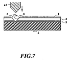
- Fig. 5 is a top plan view of planar polymer optical waveguides formed on a substrate 1.
- Line A-A' of Fig. 5 represents a location where oblique end face mirrors are to be formed, while registration markers 2 are incorporated near the location in the course of formation of the planar optical waveguides.
- Fig. 6 is a cross-sectional view of a planar optical waveguide as shown in Fig. 5, cut across the core 3 of the waveguide on line B-B' of Fig. 5.
- numeral 4 refers to an upper cladding layer and 5 to a lower cladding layer.
- the planar optical waveguide is cut along line A-A' of Fig. 5 with an eye on the markers 2 while using a diamond blade 40 having a blade tip worked to have an angle of about 90 degrees according to the present invention.
- a V-shaped groove 12a having oblique end faces (micro-mirrors) 6, 6 is formed in the planar optical waveguide.
- a cutting machine such as a dicing saw machine for use in cut-out of LSI chips and the like will suffice for cutting. Since the dicing saw machine is provided with a high-performance stage, cutting with the dicing saw machine can be done with a submicron-order positional accuracy in the horizontal direction as well as in the vertical direction.
- a general-purpose dicing saw machine for use in cut-out of LSI chips and the like may be used herein as that dicing saw machine if only the blade thereof is replaced with the blade of the present invention.
- One great advantage of the present invention is no need of special contrivance of the sample fixation method and the like.
- a cutting depth down to a location deeper than the interfacial boundary between the core 3 and the lower cladding layer 5 will suffice, so that cutting may either be stopped inside the lower cladding layer 5, or make an inroad into the substrate 1.
- One advantage of cutting lies in that selection and use of a blade made of a suitable material enables simultaneous cutting of a soft material such as a polymer, a rigid material such as silicon or glass, and a composite material of a silicon substrate and a polymer thereon, or the like.
- a fine grain size diamond blade has a fineness comparable to that of a very fine mesh abrasive paper for use in polishing of optical parts such as a lens
- the use of such a fine mesh blade makes the step of cutting exert the same effects as would be secured if cutting for oblique end face formation were effected simultaneously with optical-grade high-quality surface polishing.
- a cut surface having a very high level of smoothness.
- Such planar optical waveguides having respective formed oblique end face mirrors are peeled from the substrate 1 to produce an optical waveguide film with 45-degree oblique end face mirrors as shown in Fig. 8.
- a 45-degree oblique end face mirror has a function of 90-degree downward deflection of light 7 propagated through a planar optical waveguide as shown in Fig. 8.
- This 45-degree oblique end face mirror also has a reverse function of 90-degree deflection of light 8 propagated from below through space to effect optical coupling thereof with the planar optical waveguide.
- the planar optical waveguides may not necessarily be peeled to form a film, but may also be used as planar optical waveguides attached intact to the substrate 1 as shown in Fig. 9 but having a function of 90-degree deflection of either internally propagational light 10 or externally incident light 11 at the oblique end faces 9 thereof.
- a V-shaped groove 12b having an oblique end face 9 and a substantially vertical face 9a facing the oblique end face 9 as shown in Fig. 9 is formed midway of a planar optical waveguide, a blade having a cross section wherein only one side face thereof is set oblique and the other side face is set substantially vertical must be selected and used.
- the constitution of the present invention has hereinabove been described briefly in connection with a case where the optical deflector of the present invention comprises planar optical waveguides. Next, the constitution of the present invention will be described in connection with a case where the optical deflector of the present invention comprises a optical fiber.
- Fig. 10A is a top plan view of an optical fiber having a end portion thereof fixed on a substrate.
- numeral 21 refers to the substrate, 22 to the optical fiber, 23 to an end portion of the optical fiber 22 stripped of a cover, and 24 to an adhesive film for fixation of the end portion 23 of the optical fiber, while line A-A' represents a position where an oblique end face mirror is to be formed.
- Fig. 10B is a cross-sectional view taken on line A-A' of Fig. 10A.
- numeral 25 refers to the core of the optical fiber, and 26 to the cladding of the optical fiber.
- the optical fiber 22 has the end portion 23 fixed on the substrate 21 with the adhesive film 24.
- the substrate 21 include rigid substrates such as silicon, glass, and thick resin substrates as a matter of course, and flexible films such as a thin resin film.
- cutting along line A-A' is done using a diamond blade having a blade tip worked to be V-shaped in cross section with an angle of about 90 degrees according to the present invention, whereby a 45-degree oblique end face mirror 27 is formed at an end of the optical fiber 22.
- One advantage of cutting lies in that selection and use of a blade made of a suitable material enables simultaneous cutting of a soft material such as a polymer, a rigid material such as silicon or glass, and a composite material such as one comprising a glass optical fiber fixed on a silicon substrate with a resin adhesive, or an optical fiber sheet comprising glass optical fibers fixed in a resin. Accordingly, the process of the present invention is not only applicable to a glass optical fiber, a plastic optical fiber, and an optical fiber constituted of a plastic cladding and a glass material core, but also applicable to silicon, a glass material and resin material for use in a substrate for fixation of an optical fiber.
- a fine grain size diamond blade has a fineness comparable to that of a very fine mesh abrasive paper for use in polishing of optical parts such as a lens
- the use of such a fine mesh blade makes the step of cutting exert the same effects as would be secured if cutting for oblique end face formation were effected simultaneously with optical-grade high-quality surface polishing.
- a cut surface having a very high level of smoothness.
- the adhesive film 24 is peeled to separate the optical fiber 22 from the substrate 21, whereby an optical fiber with an oblique end face mirror as shown in Fig. 11B can be obtained.
- the 45-degree oblique end face mirror 27 has a function of 90-degree downward deflection of light 28 propagated through the optical fiber 22 as shown in Fig. 11B.
- This 45-degree oblique end face mirror also has a reverse function of 90-degree deflection of light 29 propagated from below through space to effect optical coupling thereof with the optical fiber.
- the adhesive film 24 may not necessarily be peeled, but the optical fiber attached intact to the substrate 21 as shown in Fig. 11A may also be used as an optical fiber having a function of 90-degree deflection.
- the cover is usually attached to the optical fiber in order to reinforce the latter. Although a portion of the cover where cutting is to be done is peeled before fixation of the optical fiber on the substrate in the foregoing case, preliminary peeling of the cover may not necessarily be required. Since the process of the present invention is applicable even to a composite material such as a material comprising a glass and a resin, an optical fiber having a cover attached intact thereto may be fixed on a substrate, and then cut to form an oblique end face. If the cover is made of a material poor in transparency, however, a portion of the cover near the oblique end face intercepts incident or emergent light via the oblique end face into or from the optical fiber. In this case, therefore, a portion of the cover corresponding to an end portion of the optical fiber should be peeled in this case.
- an adhesive film having a suitable adhesive power examples of which include an ultraviolet-degradable adhesive film capable of being lowered in adhesive power through degradation of an adhesive upon its absorption of ultraviolet rays.
- This ultraviolet-degradable adhesive film when used, can conveniently be peeled simply by irradiation thereof with ultraviolet rays after cutting.
- an adhesive such as an ultraviolet-curing resin or a thermosetting resin may alternatively be used for fixation of an optical fiber.
- the step of separating the optical fiber from the substrate after cutting may be carried out either by dissolving the adhesive in a solvent or by peeling the adhesive together with the optical fiber from the substrate.
- the adhesive may not necessarily be peeled for separation of the optical fiber from the substrate.
- the optical fiber attached intact to the substrate 21 as shown in Fig. 11A may be used as an optical fiber having a mechanism of 90-degree deflection of internally propagational light or externally incident light at the oblique end face 27.
- the surface smoothness of the oblique end face, affecting the reflectance of the oblique end face mirror is of course determined substantially by the mesh fineness of the surface of the blade used. Basically, the finer the diamond grain size of the blade used, the smoother the resulting mirror plane.
- use of an excessively fine grain size blade involves problems such as an incapability of cutting because of clogging, wear of the blade in a short time, and a failure in increasing the cutting speed. Accordingly, selection of a suitable blade is very important in forming a good-quality oblique end face mirror.
- Fig. 12 shows the relationship between the average grain size of diamond grains contained in a blade used for cutting and the reflectance of the resulting mirror plane as well as the maximum cutting speed attainable for good-quality mirror plane formation without troubles such as clogging.
- the average grain size of diamond grains is at least 15 ⁇ m (in the form of an aggregate of grains of 10 to 20 ⁇ m in size), the roughness of the mirror plane is so great that the reflectance is lower than 50 %. The smaller the average grain size, the higher the reflectance.
- a blade of 5 ⁇ m in average grain size in the form of an aggregate of grains of 4 to 6 ⁇ m in size
- a reflectance of about 80 % can be secured.
- the average grain size is further decreased to be as fine as 1.5 ⁇ m (in the form of an aggregate of grains of 0 to 3 ⁇ m in size)
- the mirror plane becomes optically sufficiently smooth while securing a high reflectance of at least 95 %.
- Use of a finer grain size blade makes the mirror plane smoother but so saturated in respect of optical properties as to attain little improvement in reflectance. From the standpoint of reflectance, therefore, a blade of at most 5 ⁇ m is desirably used for cutting.
- a fine grain size blade is so poorer in cutting power than a rough blade that the cutting speed is generally slowed down with a shorter life span of the blade.
- a blade of at least 1 ⁇ m in the form of an aggregate of grains of 0 to 2 ⁇ m in size
- a blade of at least 1 ⁇ m in average grain size is desirably used for cutting.
- the average grain size of diamond grains is at least 1 ⁇ m and at most 5 ⁇ m.
- a blade of 1 to 5 ⁇ m in average grain size is desirably used for cutting.
- a first method is a method wherein a surface is softened by heat. This can be simply effected in such a way that a flatiron heated up to a temperature substantially capable of slightly softening a polymer as the core material of an optical waveguide is lightly pressed against a cut surface. In this case, when the softened polymer adheres to the flatiron, no smooth surface can be obtained.
- the surface of the flatiron is desirably subjected to an adhesion-proofing treatment such as Teflon coating.
- a second method is a method wherein a surface is slightly dissolved in a suitable solvent. This can be simply effected in such a way that a cut surface is immersed in a suitable solvent capable of slightly dissolving a polymer as the core material of an optical waveguide.
- a cut surface may be immersed in a mixed solution of hydrogen fluoride and ammonium fluoride instead of an organic solvent to effect slight dissolution thereof, whereby the surface can be smoothed.
- a third method is a method wherein an oblique surface is subjected to finish polishing with a diamond blade having a by far finer average grain size than that of a blade used in cutting for oblique surface formation.
- this method after formation of a groove having a desired oblique surface by cutting, the smoothness of a cut surface can be well enhanced only by finish polishing with a replaced blade. Therefore, this method involves an advantage that the step can be simplified because a waveguide may not be transferred to another step in order to improve the smoothness of the cut surface.
- any one of the foregoing methods enables formation of an oblique end face having a very excellent smoothness.
- Such an operation of improving the smoothness of a cut oblique end face is possible because a V-shaped groove is formed in an optical waveguide as a result of cutting for formation of an oblique surface as a mirror. More specifically, this is so because a form in which the upper side of an oblique surface is widely open is materialized in the neighborhood of a mirror plane in the optical waveguide.
- optical deflector of the present invention having an oblique surface formed by such V-shaped groove formation
- various means for smoothing an oblique surface can be easily carried out as described above, and a specular treatment of an oblique surface can also be easily realized as will be described later, while securing such an advantage in packaging that an optical functional element such as a sensitive optical device or an emitting optical device can be disposed in the V-shaped groove, i.e., in the extreme proximity of a mirror plane.
- the oblique end face can be greatly smoothed according to any one of the foregoing method, there is a case where total reflection conditions on the oblique end face cannot be satisfied for all guided-wave modes though it depends on the angle of inclination of the oblique end face and the refractive index values of the core and the cladding.
- a reflectance of 100 % cannot be secured in principle because some high modes of light are not reflected on the oblique end face and are instead transmitted therethrough.
- a method of coating the cut surface with a highly reflective metal such as gold, silver or aluminum by vacuum deposition or the like is effective. A reflectance close to 100 % can be secured by such coating with a highly reflective film.
- the angle of inclination of the oblique end face i.e., the angle of inclination of the mirror
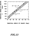
- the angle of aV-shaped groove formed by cutting usually becomes a little larger than the angle of the tip of a blade used for cutting. This is believed to be mainly caused by a dimensional error in the circumferential direction of the blade and vibration during the operation of a dicing saw machine.
- Fig. 13 shows the relationship between the vertical angle of a blade used for cutting and the vertical angle of a V-shaped groove actually formed by cutting.
- the vertical angle of the resulting V-shaped groove becomes larger by about 2 degrees than the vertical angle of the blade with a lot-to-lot variation controlled within the range of about 2 degrees.
- an oblique end face mirror having an angle of inclination of 45 degrees can be formed with a good reproducibility with an accuracy falling within the range of ⁇ 1 degree.
- suitable grain size blade is intended to indicate a blade of at least 1 ⁇ m and at most 5 ⁇ m in average grain size according to the present invention.
- a conversion difference between the vertical angle of the blade and the vertical angle of the resulting V-shaped groove is increased with increases in lot-to-lot variation and repetition errors, whereby a difficulty is encountered in controlling the angle of inclination of the oblique end face mirror with a high accuracy.
- a blade of at most 5 ⁇ m in average grain size is desirably used for cutting.
- the average grain size of constituent diamond grains of the blade is 1 to 5 ⁇ m.
- a side face of the blade for oblique surface formation is formed at an angle of inclination of 44 degrees in relation to the cutting accuracy aimed at the above-mentioned angle of inclination of the oblique end face mirror. Accordingly, when a symmetric V-shaped groove is to be formed, the angle of the tip of the blade is set to be 88 degrees.
- the optical deflector produced according to the foregoing process when mounted on a packaging substrate 42 as shown in Fig. 14, can be used as a part which constitutes an optical transmitter module wherein it deflects a laser beam 44 emitted from a surface emitting laser 43 likewise mounted on the packaging substrate 42 by means of the oblique end face 6 to effect optical coupling thereof with the optical waveguide to thereby turn the beam into a propagational light 45a, or that optical deflector, when mounted on a packaging substrate 46 as shown in Fig.
- the optical deflector when mounted on a packaging substrate 42 as shown in Fig. 16, can be used as a part which constitutes an optical transmitter module wherein it deflects a laser beam 44 emitted from a surface emitting laser 43 likewise mounted on the packaging substrate 42 by means of the oblique end face 27 to effect optical coupling thereof with the optical fiber to thereby turn the beam into a propagational light 45b, or that optical deflector, when mounted on a packaging substrate 46 as shown in Fig.
- An oblique end face mirror can be formed using a single-edged blade 50 as shown in Fig. 18 instead of the double-edged blade 40 as shown in Fig. 7.
- a single-edged blade 50 having a vertical angle of about 44 degrees is used to cut an optical waveguide of Fig. 6 to thereby form an oblique end face mirror, whereby an optical waveguide with a 45-degree oblique end face mirror as shown in Fig. 9 can be obtained.
- the oblique end face 9 since total reflection conditions on the oblique end face 9 are not satisfied, however, the oblique end face 9 must be coated with a high-reflectance metal such as gold, silver or aluminum in order to secure a high reflectance.
- a large difference in function between the oblique end face mirror 9 of a type as shown in Fig. 9 and the oblique end face mirror 6 of a type as shown in Fig. 7 is that they are reverse to each other in respect of the direction of deflection.
- the oblique end face mirror of Fig. 9 has a function of deflecting a light 10 popagated through the optical waveguide in the upward direction, i.e., in a direction opposite to the substrate 1. Of course, it also has a function of deflecting the other way around a light 11 propagated from above the substrate 1 to effect optical coupling thereof with the optical waveguide.
- an emitting optical device 43 may be disposed on the surface of the optical waveguide or in the V-shaped groove 12b to constitute an optical transmitter as shown in Fig. 19
- a sensitive optical device 49 may be disposed on the surface of the optical waveguide or in the V-shaped groove 12b to constitute an optical receiver as shown in Fig. 20, or an optical waveguide with an oblique end face mirror as shown in Fig. 8 may further be superposed on the resulting surface to produce vertically stacked optical waveguides having 2 waveguide layers 51a and 51b as shown in Fig. 21.
- this type of oblique end face mirror involves a problem of being liable to generate a light going backward toward the incident side of light, i.e., a problem of bad return loss in an aspect of an element, because of Fresnel reflection occurring on the vertical end face 9a constituting the transformed V-shaped groove 12b formed by cutting.
- a problem of bad return loss in an aspect of an element because of Fresnel reflection occurring on the vertical end face 9a constituting the transformed V-shaped groove 12b formed by cutting.
- the refractive index of the core is 1.490
- an about 3.9 % Fresnel reflection occurs on the vertical end face 9a, with the result that the return loss detected on the light-incident end face is about -14 dB without regard for the propagation loss of the optical waveguide.
- Means for solving this problem include the following two methods.
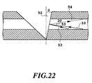
- the end face 9a of the optical waveguide is formed into an end face oblique by a slight angle ⁇ relative to a vertical plane as shown in Fig. 22.
- the optical path 53 of reflected light is deflected by an angle 2 ⁇ in comparison with the optical path 54 of reflected light in the case where the end face 9a is not oblique. This can be utilized with proper selection of ⁇ to diffuse reflected light out of the waveguide, whereby the return loss can consequently be improved.
- the angle of a wave-guided light capable of being propagated through a waveguide with the optical axis of the waveguide has the maximum value: cos -1 (n clad /n core ) wherein n core is the refractive index of the core and n clad is the refractive index of the cladding. Accordingly, when the value of ⁇ is set to be higher than the value of cos -1 (n clad /n core ) , all reflected light can be diffused out of the waveguide.
- this value of cos -1 (n clad /n core ) is about 5° to 6° in the case of a single-mode waveguide wherein the number of apertures (NA) is about 0.1, and is about 8° to 9° in the case of a multimode waveguide wherein the number of apertures (NA) is about 0.2, the return loss can be drastically decreased through inclination of the end face 9a by an angle of at least 6° in the case of the single-mode waveguide or by an angle of at least 9° in the case of the multimode waveguide.
- Fig. 23 shows the ⁇ dependence of the transmittance and the return loss. When the value of ⁇ is at least 1°, the return loss is at most -20 dB. On the other hand, when the value of ⁇ exceeds 30°, the transmittance is abruptly decreased.
- the value of ⁇ is advantageously set to be in the range of 1° to 30°.
- the vertical side face of a single-edged blade In order to form such a transformed V-shaped groove, the vertical side face of a single-edged blade must be inclined by an angle of 1° to 30°.
- a single-edged blade in such a form is also one modification of the blade of the present invention.
- the corresponding vertical end face may be provided with a slight inclination, whereby the resultant element can be improved in respect of return loss.
- the angle of polarization of an optical path by the mirror is changed because the resulting end face 52 has such an inclination as to give rise to refraction in the core/cladding interface thereof.
- a light beam 10 is polarized by an angle: sin -1 (n core sin ⁇ ) - ⁇ by refraction to be propagated while following a course as shown by a broken line 62 ⁇ 63.
- the polarization angle of emergent light 63 with incident light 10 must be set to be 2 ⁇ + ⁇ sin -1 (n core sin ⁇ ) - ⁇ /2 .
- the second method is a method wherein a gap between the end face 52 of the waveguide and the oblique end face 9 is filled with a resin 70 or the like having substantially the same refractive index as that of the core after the oblique end face 9 is coated with a highly reflective film made of gold or the like. Substitution of air with the resin 70 as the medium in the V-shaped groove 12b can drastically decrease Fresnel reflection occurring on the end face 52 of the waveguide.
- the refractive index of the resin 70 is n resin
- the change in the polarization angle of the optical path is sin -1 ⁇ (n core /n resin ) sin ⁇ - ⁇ .
- This resin 70 is also effective in protecting the oblique end face mirror 9.
- the optical deflector of the present invention comprising a planar optical waveguide, not only the operation of cutting the whole element transversely but also localized formation of an oblique end face mirror at an arbitrary position of an optical waveguide is possible.
- oblique end face mirrors must be formed at positions 72, 73 and 74 of a Y-branched optical waveguide as shown in Fig.
- a high-performance reflection type optical deflector can be easily produced with a high accuracy according to the process of the present invention for producing an optical deflector.
- An embedded optical waveguide comprising a core of polymethyl methacrylate and a cladding of an epoxy resin was formed on a silicon substrate.
- the refractive indices of the core and the cladding were 1.490 and 1.475, respectively, while the cross section of the core was square with a width of 40 ⁇ m and a height of 40 ⁇ m.
- a blade 82 having a blade tip worked to be V-shaped in cross section with a vertical angle of 88 degrees as shown in Fig. 27 was used to cut one end portion of the optical waveguide down to the very surface of the substrate to thereby form an oblique end face. Thereafter, a piece of 5 cm in length and 1 cm in width was cut out of the resulting product.
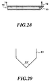
- the optical waveguide was then peeled from the substrate to produce a waveguide film type optical deflector as shown in Fig. 28.
- a laser beam 76 of 0.85 ⁇ m in wavelength was cast into the produced waveguide film type optical deflector via the vertical end face 75 thereof to examine an intensity profile in far visual field of reflected light 78 resulting from reflection on the oblique end face 77 thereof, whereby the angle of deflection was measured.
- the angle of deflection was 90 degrees.
- the total light intensity of the reflected light was measured with an optical detector to examine the reflectance of the oblique end face as a mirror, which was found to be 83 %.
- a flatiron heated at a temperature of 180°C was pressed against the oblique end face 77 of a waveguide film type optical deflector produced in the same manner as in Example 1 to effect a planarization treatment thereof. Thereafter, the angle of deflection and reflectance of the oblique end face mirror were measured to be 90 degrees and 85 %, respectively.
- the oblique end face 77 of a waveguide film type optical deflector produced in the same manner as in Example 1 was immersed in methyl isobutyl ketone to effect a planarization treatment thereof. Thereafter, the angle of deflection and reflectance of the oblique end face mirror were measured to be 90 degrees and 85 %, respectively.
- the oblique end face 77 of a waveguide film type optical deflector produced in the same manner as in Example 1 was immersed in chlorobenzene to effect a planarization treatment thereof. Thereafter, the angle of deflection and reflectance of the oblique end face mirror were measured to be 90 degrees and 85 %, respectively.
- the oblique end face 77 of a waveguide film type optical deflector produced in the same manner as in Example 1 was metallized with gold by vacuum deposition. Thereafter, the angle of deflection and reflectance of the oblique end face mirror were measured to be 90 degrees and 97 %, respectively.
- the oblique end face 77 of a waveguide film type optical deflector produced in the same manner as in Example 1 was metallized with silver by vacuum deposition. Thereafter, the angle of deflection and reflectance of the oblique end face mirror were measured to be 90 degrees and 96 %, respectively.
- the oblique end face 77 of a waveguide film type optical deflector produced in the same manner as in Example 1 was metallized with aluminum by vacuum deposition. Thereafter, the angle of deflection and reflectance of the oblique end face mirror were measured to be 90 degrees and 90 %, respectively.
- An embedded optical waveguide comprising a core of polymethyl methacrylate and a cladding of an epoxy resin was formed on a silicon substrate.
- the refractive indices of the core and the cladding were 1.490 and 1.475, respectively, while the cross section of the core was square with a width of 40 ⁇ m and a height of 40 ⁇ m.
- a blade 83 having a blade tip worked to be V-shaped in cross section with a vertical angle of 93 degrees as shown in Fig. 29 was used to cut one end portion of the optical waveguide down to the very surface of the substrate to thereby form an oblique end face. Thereafter, a piece of 5 cm in length and 1 cm in width was cut out of the resulting product.
- the optical waveguide was then peeled from the substrate to produce a waveguide film type optical deflector.
- a laser beam of 0.85 ⁇ m in wavelength was cast into the produced waveguide film type optical deflector via the vertical end face thereof to examine an intensity profile in far visual field of reflected light resulting from reflection on the oblique end face thereof, whereby the angle of deflection was measured.
- the angle of deflection was 85 degrees.
- the total light intensity of the reflected light was measured with an optical detector to examine the reflectance of the oblique end face as a mirror, which was found to be 95 %.
- a flatiron heated at a temperature of 180°C was pressed against the oblique end face of a waveguide film type optical deflector produced in the same manner as in Example 8 to effect a planarization treatment thereof. Thereafter, the angle of deflection and reflectance of the oblique end face mirror were measured to be 85 degrees and 97 %, respectively.
- the oblique end face of a waveguide film type optical deflector produced in the same manner as in Example 8 was immersed in methyl isobutyl ketone to effect a planarization treatment thereof. Thereafter, the angle of deflection and reflectance of the oblique end face mirror were measured to be 85 degrees and 97 %, respectively.
- the oblique end face of a waveguide film type optical deflector produced in the same manner as in Example 8 was immersed in chlorobenzene to effect a planarization treatment thereof. Thereafter, the angle of deflection and reflectance of the oblique end face mirror were measured to be 85 degrees and 97 %, respectively.
- An embedded optical waveguide comprising a core of polymethyl methacrylate and a cladding of an epoxy resin was formed on a silicon substrate.
- the refractive indices of the core and the cladding were 1.490 and 1.475, respectively, while the cross section of the core was square with a width of 40 ⁇ m and a height of 40 ⁇ m.
- a blade 84 having a blade tip worked to be cuneiform in cross section with a vertical angle of 44 degrees as shown in Fig. 30 was used to cut one end portion of the optical waveguide down to the very surface of the substrate to thereby form an oblique end face 99, which was then metallized with gold 103 by vacuum deposition. Thereafter, a piece of 5 cm in length and 2 cm in width was cut out of the resulting product to produce a waveguide film type optical deflector as shown in Fig. 31.
- a laser beam 101 of 0.85 ⁇ m in wavelength was cast into the produced waveguide film type optical deflector via the vertical end face 100 thereof to examine an intensity profile in far visual field of reflected light 102 resulting from reflection on the oblique end face 99 thereof, whereby the angle of deflection was measured.
- the angle of deflection was 90 degrees.
- the total light intensity of the reflected light was measured with an optical detector to examine the reflectance of the oblique end face as a mirror, which was found to be 96 %. Further, the intensity of light returned to the light-incident end face of the waveguide was measured to examine the return loss, which was found to be -15 dB.
- a waveguide film type optical deflector was produced in substantially the same manner as in Example 12 except that silver was used as the metal for vacuum deposition on the oblique end face.
- a laser beam of 0.85 ⁇ m in wavelength was cast into the produced waveguide film type optical deflector via the vertical end face thereof to examine an intensity profile in far visual field of reflected light resulting from reflection on the oblique end face thereof, whereby the angle of deflection was measured.
- the angle of deflection was 90 degrees.
- the total light intensity of the reflected light was measured with an optical detector to examine the reflectance of the oblique end face as a mirror, which was found to be 95 %.
- a waveguide film type optical deflector was produced in substantially the same manner as in Example 12 except that aluminum was used as the metal for vacuum deposition on the oblique end face.
- a laser beam of 0.85 ⁇ m in wavelength was cast into the produced waveguide film type optical deflector via the vertical end face thereof to examine an intensity profile in far visual field of reflected light resulting from reflection on the oblique end face thereof, whereby the angle of deflection was measured.
- the angle of deflection was 90 degrees.
- the total light intensity of the reflected light was measured with an optical detector to examine the reflectance of the oblique end face as a mirror, which was found to be 89 %.
- a 1 ⁇ 2Y branched embedded optical waveguide comprising a core of polymethyl methacrylate and a cladding of an epoxy resin as shown in Fig. 26 was formed on a silicon substrate.
- the total length of the optical waveguide was 5 cm, and the distance between the centers of the two branched cores was 2.5 mm.
- the refractive indices of the core and the cladding were 1.490 and 1.475, respectively, while the cross section of the core was square with a width of 40 ⁇ m and a height of 40 ⁇ m.
- the thickness of the lower cladding layer was 20 ⁇ m, while the thickness of the upper cladding layer was 60 ⁇ m (20 ⁇ m from the upper surface of the core).
- a blade 84 having a blade tip worked to be cuneiform in cross section with a vertical angle of 44 degrees as shown in Fig. 30 was used to cut the optical waveguide at positions 72, 73 and 74 thereof as shown in Fig. 26 and down to the very surface of the substrate to thereby form oblique end faces, which were then metallized with gold by vacuum deposition. Thereafter, a surface emitting laser of 0.85 ⁇ m in oscillation wavelength was mounted over the oblique end face as a mirror formed at the position 72 in such a way that the emitting surface thereof faced the mirror, while photodiodes were respectively mounted over the oblique end faces as mirrors formed at the positions 73 and 74 in such a way that the sensitive surfaces thereof faced the respective mirrors.
- An electric current was injected into the surface emitting laser to emit a laser beam (0.80 mW), which was propagated through the waveguide via the mirror, and received by the photodiodes via the mirrors to measure the powers of the received laser beams.
- the intensities of the laser beams received at the positions 73 and 74 were 0.32 mW and 0.31 mW, respectively.
- Polymer A Two deuterated polyfluoromethacrylates differing in copolymerization ratio (hereinafter referred to as "Polymer A” and “Polymer B,” see “Japanese Patent Application No. 282,023/1990 directed to a plastic optical waveguide”) were synthesized.
- the refractive indices of Polymer A and Polymer B were 1.490 and 1.483, respectively.
- a single-mode embedded optical waveguide comprising a core of Polymer A and a cladding of Polymer B was formed on a silicon substrate.
- the cross section of the core was square with a width of 7 ⁇ m and a height of 7 ⁇ m.
- the thickness of the lower cladding layer was 20 ⁇ m, while the thickness of the upper cladding layer was 27 ⁇ m (20 ⁇ m from the upper surface of the core).
- An epoxy resin of 50 ⁇ m in thickness was applied on the upper cladding layer for the purpose of reinforcement.
- a blade 82 having a blade tip worked to be V-shaped in cross section with a vertical angle of 88 degrees as shown in Fig. 27 was used to cut one end portion of the optical waveguide down to the very surface of the substrate to thereby form an oblique end face. Thereafter, a piece of 5 cm in length and 1 cm in width was cut out of the resulting product.
- the optical waveguide was then peeled from the substrate to produce a waveguide film type optical deflector.
- a laser beam of 1.3 ⁇ m in wavelength was cast into the produced waveguide film type optical deflector via the vertical end face thereof to examine an intensity profile in far visual field of reflected light resulting from reflection on the oblique end face thereof, whereby the angle of deflection was measured.
- the angle of deflection was 90 degrees.
- the total light intensity of the reflected light was measured with an optical detector to examine the reflectance of the oblique end face as a mirror, which was found to be 78 %.
- a flatiron heated at a temperature of 180°C was pressed against the oblique end face of a waveguide film type optical deflector produced in the same manner as in Example 16 to effect a planarization treatment thereof. Thereafter, the angle of deflection and reflectance of the oblique end face mirror were measured to be 90 degrees and 80 %, respectively.
- the oblique end face of a waveguide film type optical deflector produced in the same manner as in Example 16 was immersed in methyl isobutyl ketone to effect a planarization treatment thereof. Thereafter, the angle of deflection and reflectance of the oblique end face mirror were measured to be 90 degrees and 80 %, respectively.
- the oblique end face of a waveguide film type optical deflector produced in the same manner as in Example 16 was immersed in chlorobenzene to effect a planarization treatment thereof. Thereafter, the angle of deflection and reflectance of the oblique end face mirror were measured to be 90 degrees and 80 %, respectively.
- the oblique end face of a waveguide film type optical deflector produced in the same manner as in Example 16 was metallized with gold by vacuum deposition. Thereafter, the angle of deflection and reflectance of the oblique end face mirror were measured to be 90 degrees and 94 %, respectively.
- the oblique end face of a waveguide film type optical deflector produced in the same manner as in Example 16 was metallized with silver by vacuum deposition. Thereafter, the angle of deflection and reflectance of the oblique end face mirror were measured to be 90 degrees and 92 %, respectively.
- the oblique end face of a waveguide film type optical deflector produced in the same manner as in Example 16 was metallized with aluminum by vacuum deposition. Thereafter, the angle of deflection and reflectance of the oblique end face mirror were measured to be 87 degrees and 89 %, respectively.
- Polymer C Two deuterated polysiloxanes differing in copolymerization ratio (hereinafter referred to as "Polymer C” and “Polymer D,” see “Japanese Patent Application No. 282,023/1990 directed to a plastic optical waveguide”) were synthesized.
- the refractive indices of Polymer A and Polymer B were 1.545 and 1.537, respectively.
- a single-mode embedded optical waveguide comprising a core of Polymer C and a cladding of Polymer D was formed on a silicon substrate.
- the cross section of the core was square with a width of 7 ⁇ m and a height of 7 ⁇ m.
- the thickness of the lower cladding layer was 20 ⁇ m, while the thickness of the upper cladding layer was 27 ⁇ m (20 ⁇ m from the upper surface of the core).
- An epoxy resin of 50 ⁇ m in thickness was applied on the upper cladding layer for the purpose of reinforcement.
- a blade 82 having a blade tip worked to be V-shaped in cross section with a vertical angle of 88 degrees as shown in Fig. 27 was used to cut one end portion of the optical waveguide down to the very surface of the substrate to thereby form an oblige end face. Thereafter, apiece of 5 cm in length and 1 cm in width was cut out of the resulting product.
- the optical waveguide was then peeled from the substrate to produce a waveguide film type optical deflector.
- a laser beam of 1.55 ⁇ m in wavelength was cast into the produced waveguide film type optical deflector via the vertical end face thereof to examine an intensity profile in far visual field of reflected light resulting from reflection on the oblique end face thereof, whereby the angle of deflection was measured.
- the angle of deflection was 90 degrees.
- the total light intensity of the reflected light was measured with an optical detector to examine the reflectance of the oblique end face as a mirror, which was found to be 80 %.
- a flatiron heated at a temperature of 400°C was pressed against the oblique end face of a waveguide film type optical deflector produced in the same manner as in Example 23 to effect a planarization treatment thereof. Thereafter, the angle of deflection and reflectance of the oblique end face mirror were measured to be 90 degrees and 83 %, respectively.
- the oblique end face of a waveguide film type optical deflector produced in the same manner as in Example 23 was immersed in anisole to effect a planarization treatment thereof. Thereafter, the angle of deflection and reflectance of the oblique end face mirror were measured to be 90 degrees and 83 %, respectively.
- the oblique end face of a waveguide film type optical deflector produced in the same manner as in Example 23 was immersed in chlorobenzene to effect a planarization treatment thereof. Thereafter, the angle of deflection and reflectance of the oblique end face mirror were measured to be 90 degrees and 83 %, respectively.
- the oblique end face of a waveguide film type optical deflector produced in the same manner as in Example 23 was metallized with gold by vacuum deposition. Thereafter, the angle of deflection and reflectance of the oblique end face mirror were measured to be 90 degrees and 93 %, respectively.
- the oblique end face of a waveguide film type optical deflector produced in the same manner as in Example 23 was metallized with silver by vacuum deposition. Thereafter, the angle of deflection and reflectance of the oblique end face mirror were measured to be 90 degrees and 92 %, respectively.
- the oblique end face of a waveguide film type optical deflector produced in the same manner as in Example 23 was metallized with aluminum by vacuum deposition. Thereafter, the angle of deflection and reflectance of the oblique end face mirror were measured to be 90 degrees and 87 %, respectively.
- a quartz glass optical waveguide was formed on a quartz substrate.
- the refractive indices of the core and the cladding were 1.473 and 1.459, respectively.
- the cross section of the core was square with a width of 40 ⁇ m and a height of 40 ⁇ m.
- the thickness of the lower cladding layer was 20 ⁇ m, while the thickness of the upper cladding layer was 40 ⁇ m (20 ⁇ m from the upper surface of the core).
- a blade 82 having a blade tip worked to be V-shaped in cross section with a vertical angle of 88 degrees as shown in Fig. 27 was used to cut one end portion of the optical waveguide down to the very surface of the substrate to thereby form an oblique end face. Thereafter, a piece of 5 cm in length and 1 cm in width was cut out of the resulting product to produce a waveguide type optical deflector.
- a laser beam of 0.85 ⁇ m in wavelength was cast into the produced waveguide type optical deflector via the vertical end face thereof to examine an intensity profile in far visual field of reflected light resulting from reflection on the oblique end face thereof, whereby the angle of deflection was measured.
- the angle of deflection was 90 degrees.
- the total light intensity of the reflected light was measured with an optical detector to examine the reflectance of the oblique end face as a mirror, which was found to be 78 %.
- the oblique end face of a waveguide film type optical deflector produced in the same manner as in Example 30 was immersed in a mixed solution of hydrogen fluoride and ammonium fluoride to effect a planarization treatment thereof. Thereafter, the angle of deflection and reflectance of the oblique end face mirror were measured to be 90 degrees and 80 %, respectively.
- the oblique end face of a waveguide film type optical deflector produced in the same manner as in Example 30 was metallized with gold by vacuum deposition. Thereafter, the angle of deflection and reflectance of the oblique end face mirror were measured to be 90 degrees and 93 %, respectively.
- the oblique end face of a waveguide film type optical deflector produced in the same manner as in Example 30 was metallized with silver by vacuum deposition. Thereafter, the angle of deflection and reflectance of the oblique end face mirror were measured to be 90 degrees and 92 %, respectively.
- the oblique end face of a waveguide film type optical deflector produced in the same manner as in Example 30 was metallized with aluminum by vacuum deposition. Thereafter, the angle of deflection and reflectance of the oblique end face mirror were measured to be 88 degrees and 88 %, respectively.
- a silica-based single-mode optical waveguide was formed on a quartz substrate.
- the refractive indices of the core and the cladding were 1.455 and 1.444, respectively.
- the cross section of the core was square with a width of 7 ⁇ m and a height of 7 ⁇ m.
- a blade 84 having a blade tip worked to be cuneiform in cross section with a vertical angle of 44 degrees as shown in Fig. 30 was used to cut one end portion of the optical waveguide down to the very surface of the substrate to thereby form an oblique end face, which was then metallized with gold by vacuum deposition. Thereafter, a piece of 5 cm in length and 2 cm in width was cut out of the resulting product to produce a waveguide type optical deflector.
- a laser beam of 1.55 ⁇ m in wavelength was cast into the produced waveguide type optical deflector via the vertical end face thereof to examine an intensity profile in far visual field of reflected light resulting from reflection on the oblique end face thereof, whereby the angle of deflection was measured.
- the angle of deflection was 90 degrees.
- the total light intensity of the reflected light was measured with an optical detector to examine the reflectance of the oblique end face as a mirror, which was found to be 94 %.
- An ultraviolet-curable resin of 1.485 in reflective index was cast in the cuneiform groove in the optical deflector produced in Example 12, and then cured by irradiation with ultraviolet rays. Thereafter, a piece of 5 cm in length and 2 cm in width was cut out of the resulting product to produce a waveguide type optical deflector.
- a laser beam of 0.85 ⁇ m in wavelength was cast into the produced waveguide type optical deflector to examine an intensity profile in far visual field of reflected light resulting from reflection on the oblique end face thereof, whereby the angle of deflection was measured.
- the angle of deflection was 90 degrees.
- the total light intensity of the reflected light was measured with an optical detector to examine the reflectance of the oblique end face as a mirror, which was found to be 97 %. Further, the intensity of light returned to the light-incident end face of the waveguide was measured to examine the return loss, which was found to be at most -55 dB.
- An embedded optical waveguide comprising a core of polymethyl methacrylate and a cladding of an epoxy resin was formed on a silicon substrate.
- the refractive indices of the core and the cladding were 1.490 and 1.475, respectively, while the cross section of the core was square with a width of 40 ⁇ m and a height of 40 ⁇ m.
- a blade 85 having a blade tip worked to be cuneiform in cross section with a vertical angle of 55.5 degrees as shown in Fig. 32 was used to cut one end portion of the optical waveguide down to the very surface of the substrate to thereby form a V-shaped groove as shown in Fig. 24.
- the angle ⁇ of the end face 52 with a vertical plane was 10 degrees, while the angle ⁇ of the oblique end face 9 with the optical axis of the waveguide was 42.5 degrees.
- the oblique end face 9 was then metallized with gold by vacuum deposition. Thereafter, a piece of 5 cm in length and 2 cm in width was cut out of the resulting product to produce a waveguide type optical deflector.
- a laser beam of 0.85 ⁇ m in wavelength was cast into the produced waveguide type optical deflector to examine an intensity profile in far visual field of reflected light 63 resulting from reflection on the oblique end face 9 thereof, whereby the angle of deflection was measured.
- the angle of deflection was 90 degrees.
- the total light intensity of the reflected light was measured with an optical detector to examine the reflectance of the oblique end face as a mirror, which was found to be 95 %. Further, the intensity of light returned to the light-incident end face of the waveguide was measured to examine the return loss, which was found to be at most -50 dB.
- An embedded optical waveguide comprising a core of polymethyl methacrylate and a cladding of an epoxy resin was formed on a silicon substrate.
- the refractive indices of the core and the cladding were 1.490 and 1.475, respectively, while the cross section of the core was square with a width of 40 ⁇ m and a height of 40 ⁇ m.
- a blade 86 having a blade tip worked to be cuneiform in cross section with a vertical angle of 53 degrees as shown in Fig. 33 was used to cut one end portion of the optical waveguide down to the very surface of the substrate to thereby form a V-shaped groove as shown in Fig. 24.
- the angle ⁇ of the end face 52 with a vertical plane was 10 degrees, while the angle ⁇ of the oblique end face 9 with the optical axis of the waveguide was 45 degrees.
- the oblique end face 9 was then metallized with gold by vacuum deposition. Thereafter, an ultraviolet-curing resin 70 of 1.485 in refractive index was cast in this V-shaped groove (Fig. 25), and then cured by irradiation with ultraviolet rays. Thereafter, a piece of 5 cm in length and 2 cm in width was cut out of the resulting product to produce a waveguide film type optical deflector.
- a laser beam of 0.85 ⁇ m in wavelength was cast into the produced planar waveguide type optical deflector to examine an intensity profile in far visual field of reflected light 63 resulting from reflection on the oblique end face 9 thereof, whereby the angle of deflection was measured.
- the angle of deflection was 90 degrees.
- the total light intensity of the reflected light was measured with an optical detector to examine the reflectance of the oblique end face as a mirror, which was found to be 96 %. Further, the intensity of light returned to the light-incident end face of the waveguide was measured to examine the return loss, which was found to be at most -70 dB.
- Examples 1 to 38 are each related to a planar waveguide type optical deflector.
- the following Examples will illustrate an optical fiber type optical deflector.
- Example 39 according to the present invention will be described while referring to Figs. 10 and 11.
- numeral 21 refers to a silicon substrate, 22 to an optical fiber, 23 to an end portion of the optical fiber, 24 to an adhesive film, 25 to the core of the optical fiber, 26 to the cladding of the optical fiber, 27 to an oblique end face, 28 to a light being propagated through the optical fiber, 29 to a light being propagated downward out of the optical fiber through deflection by the oblique end face mirror or a light being cast into the optical fiber from below out of the optical fiber via the oblique end face mirror, 30 to an oblique end face, 31 to a light being propagated through the optical fiber, and 32 to a light being propagated upward out of the optical fiber through deflection by the oblique end face mirror or a light being cast into the optical fiber from above out of the optical fiber via the oblique end face mirror.
- the one exposed end portion 23 of the graded index multimode optical fiber 22 of 50 ⁇ m in core diameter was placed on the silicon substrate 21, and then fixed using the ultraviolet-curing adhesive film 24 in such a way that the whole end portion and part of the unexposed portion were covered with the adhesive film 24 as shown in Fig. 10.
- a diamond blade 82 having a blade tip worked to be V-shaped in cross section with a vertical angle of 88 degrees as shown in Fig. 27 was then used to cut the optical fiber down to the very surface of the substrate to thereby form an oblique end face 27.
- the adhesive film 24 was then irradiated with ultraviolet rays, and peeled to separate the optical fiber 22 from the silicon substrate 21 to thereby produce an optical fiber with an oblique end face mirror as shown in Fig. 11B.
- a laser beam of 0.85 ⁇ m in wavelength was cast into the produced optical fiber with the oblique end face mirror via the other end thereof to examine an intensity profile in far visual field of reflected light resulting from reflection on the oblique end face 27 thereof, whereby the angle of deflection was measured.
- the angle of deflection was 90 degrees.
- the total light intensity of the reflected light was measured with an optical detector to examine the reflectance of the oblique end face mirror, which was found to be 78 %.
- the oblique end face of an optical fiber with an oblique end face mirror produced in the same manner as in Example 39 was immersed in a mixed solution of hydrogen fluoride and ammonium fluoride to effect a smoothing treatment thereof. Thereafter, the angle of deflection and reflectance of the oblique end face mirror were measured to be 90 degrees and 80 %, respectively.
- the oblique end face of an optical fiber with an oblique end face mirror produced in the same manner as in Example 39 was metallized with gold by vacuum deposition. Thereafter, the angle of deflection and reflectance of the oblique end face mirror were measured to be 90 degrees and 93 %, respectively.
- the oblique end face of an optical fiber with an oblique end face mirror produced in the same manner as in Example 39 was metallized with silver by vacuum deposition. Thereafter, the angle of deflection and reflectance of the oblique end face mirror were measured to be 90 degrees and 92 %, respectively.
- the oblique end face of an optical fiber with an oblique end face mirror produced in the same manner as in Example 39 was metallized with aluminum by vacuum deposition. Thereafter, the angle of deflection and reflectance of the oblique end face mirror were measured to be 88 degrees and 88 %, respectively.
- An optical fiber with an oblique end face mirror was produced in substantially the same manner as in Example 39 except that use was made of a V-shaped blade with a vertical angle of 108 degrees.
- a laser beam of 0.85 ⁇ m in wavelength was cast into the produced optical fiber with the oblique end face mirror via the other end thereof to examine an intensity profile in far visual field of reflected light resulting from reflection on the oblique end face thereof, whereby the angle of deflection was measured.
- the angle of deflection was 70 degrees.
- the total light intensity of the reflected light was measured with an optical detector to examine the reflectance of the oblique end face mirror, which was found to be 93 %.
- One end portion of a graded index multimode optical fiber 22 of 50 ⁇ m in core diameter was placed on a silicon substrate 21, and then fixed using an adhesive film 24 having a strong adhesive power as shown in Fig. 10.
- a diamond blade 84 having a blade tip worked to be single-edged in cross section with a vertical angle of 44 degrees as shown in Fig. 30 was then used to cut the optical fiber down to the very surface of the substrate to thereby form an oblique end face, which was then metallized with gold by oblique vacuum deposition to produce an optical fiber with an oblique end face mirror as shown in Fig. 11C.
- a laser beam of 0.85 ⁇ m in wavelength was cast into the produced optical fiber with the oblique end face mirror via the other end thereof to examine an intensity profile in far visual field of reflected light 30 resulting from reflection on the oblique end face thereof, whereby the angle of deflection was measured.
- the angle of deflection was 90 degrees.
- the total light intensity of the reflected light was measured with an optical detector to examine the reflectance of the oblique end face mirror, which was found to be 94 %.
- a step index single-mode optical fiber of 10 ⁇ m in core diameter was worked and processed in the same manner as in Example 39 to produce an optical fiber with an oblique end face mirror.
- a laser beam of 1.55 ⁇ m in wavelength was cast into the produced optical fiber with the oblique end face mirror via the other end thereof to examine an intensity profile in far visual field of reflected light resulting from reflection on the oblique end face thereof, whereby the angle of deflection was measured.
- the angle of deflection was 90 degrees.
- the total light intensity of the reflected light was measured with an optical detector to examine the reflectance of the oblique end face mirror, which was found to be 92 %.
- the oblique end face of an optical fiber with an oblique end face mirror produced in the same manner as in Example 46 was immersed in a mixed solution of hydrogen fluoride and ammonium fluoride to effect a smoothing treatment thereof. Thereafter, the angle of deflection and reflectance of the oblique end face mirror were measured to be 90 degrees and 94 %, respectively.
- a step index single-mode optical fiber of 10 ⁇ m in core diameter was worked and processed in the same manner as in Example 45 to produce an optical fiber with an oblique end face mirror.
- a laser beam of 1.55 ⁇ m in wavelength was cast into the produced optical fiber with the oblique end face mirror via the vertical end thereof to examine an intensity profile in far visual field of reflected light resulting from reflection on the oblique end face thereof, whereby the angle of deflection was measured.
- the angle of deflection was 90 degrees.
- the total light intensity of the reflected light was measured with an optical detector to examine the reflectance of the oblique end face mirror, which was found to be 93 %.
- Example 49 according to the present invention will be described while referring to Figs. 34 and 35.
- a four-core optical fiber ribbon 107 comprising graded index multimode optical fibers 110 of 50 ⁇ m in core diameter covered with a covering material 109, while still having the covering material, was placed on a silicon substrate 106, and then fixed using an ultraviolet-degradable adhesive film 108 as shown in Figs. 34A and 34B.
- Each optical fiber 110 comprised a core 111 and a cladding 112 wrapping the core.
- a diamond blade 82 having a blade tip worked to be V-shaped in cross section with a vertical angle of 88 degrees as shown in Fig. 27 was then used to cut the optical fibers 110 down to the very surface of the substrate 106 to thereby form oblique end faces 113 (see Fig. 35A).
- the adhesive film 108 was then irradiated with ultraviolet rays, and then peeled to separate the optical fiber ribbon 107 from the silicon substrate 106.
- the covering material 109 in the end portion was then peeled to produce an optical fiber ribbon 107 with oblique end face mirrors as shown in Fig. 35B.
- a laser beam of 0.85 ⁇ m in wavelength was cast into each of the four produced optical fibers each with an oblique end face mirror via the other end thereof, where no oblique end face mirror was formed, to examine an intensity profile in far visual field of reflected light resulting from reflection on the oblique end face 113 thereof, whereby the angle of deflection was measured.
- the average angle of deflection was 90 degrees with a dispersion of at most 1 degree.
- the total light intensity of the reflected light was measured with an optical detector to examine the reflectance of the oblique end face mirror, which was found to be 78 % on the average with a dispersion of at most 2 %.
- the oblique end faces of an optical fiber ribbon with oblique end face mirrors produced in the same manner as in Example 49 were immersed in a mixed solution of hydrogen fluoride and ammonium fluoride to effect a smoothing treatment thereof. Thereafter, the angle of deflection and reflectance of every oblique end face mirror were measured to be 90 degrees on the average (dispersion: at most 1 degree) and 80 % on the average (dispersion: at most 2 %), respectively.
- the oblique end faces of an optical fiber ribbon with oblique end face mirrors produced in the same manner as in Example 49 were metallized with gold by vacuum deposition. Thereafter, the angle of deflection and reflectance of every oblique end face mirror were measured to be 90 degrees on the average (dispersion: at most 1 degree) and 94 % on the average (dispersion: at most 2 %), respectively.
- Example 52 according to the present invention will be described while referring to Figs. 36 and 37.
- One end portion of a four-core optical fiber ribbon 117 comprising graded index multimode optical fibers 118 of 50 ⁇ m in core diameter (cores 121 and claddings 122) was stripped of a cover, then disposed on a glass substrate 116 having V-shaped fixation grooves 120 formed therein in such a way as to put the optical fibers 118 in and along the respective fixation grooves 120, and then fixed using an ultraviolet-cured resin 119 as shown in Figs. 36A and 36B.
- a diamond blade 84 having a blade tip worked to be single-edged in cross section with a vertical angle of 44 degrees as shown in Fig.
- a laser beam of 0.85 ⁇ m in wavelength was cast into every produced optical fiber with an oblique end face mirror via the other end thereof to examine an intensity profile in far visual field of reflected light resulting from reflection on the oblique end face 123 thereof, whereby the angle of deflection was measured.
- the average angle of deflection was 90 degrees with a dispersion of at most 1 degree.
- the total light intensity of the reflected light was measured with an optical detector to examine the reflectance of the oblique end face mirror, which was found to be 94 % on the average with a dispersion of at most 2 %. Further, the intensity of light returned to the light-incident end face of every optical fiber was measured to examine the return loss, which was found to be at most -15 dB on the average.
- a diamond blade worked to be single-edged with a vertical angle of 44 degrees was used to partially cut an optical fiber sheet comprising 12 graded index multimode optical fibers 124 of 50 ⁇ m in core diameter embedded in a resin 125 as shown in Fig. 38 at a location denoted by numeral 127 in Fig. 38 to thereby form oblique end faces, which were then metallized with gold by oblique vacuum deposition to form deflective mirrors (oblique end faces).
- a laser beam of 0.85 ⁇ m in wavelength was cast into every optical fiber via the end thereof on the side of connectors 126 to examine an intensity profile in far visual field of reflected light resulting from reflection at the location 127, where the oblique end face mirrors were formed, whereby the angle of deflection was measured for 8 optical fibers wherein the oblique end face mirrors were formed.
- the average angle of deflection was 90 degrees with a dispersion of at most 1 degree.
- the total light intensity of the reflected light was measured with an optical detector to examine the reflectance of every oblique end face mirror, which was found to be 94 % on the average with a dispersion of at most 2 %.
- a laser beam of 0.85 ⁇ m in wavelength was cast into the produced plastic optical fiber with the oblique end face mirror via the other end thereof to examine an intensity profile in far visual field of reflected light resulting from reflection on the oblique end face thereof, whereby the angle of deflection was measured.
- the angle of deflection was 90 degrees.
- the total light intensity of the reflected light was measured with an optical detector to examine the reflectance of the oblique end face mirror, which was found to be 68 %.
- a flatiron heated at a temperature of 180°C was pressed against the oblique end face of a plastic optical fiber produced in the same manner as in Example 54 to effect a smoothing treatment thereof. Thereafter, the angle of deflection and reflectance of the oblique end face mirror were measured to be 90 degrees and 71 %, respectively.
- the oblique end face of a plastic optical fiber with an oblique end face mirror produced in the same manner as in Example 54 was immersed in methyl isobutyl ketone to effect a smoothing treatment thereof. Thereafter, the angle of deflection and reflectance of the oblique end face mirror were measured to be 90 degrees and 70 %, respectively.
- the oblique end face of a plastic optical fiber with an oblique end face mirror produced in the same manner as in Example 54 was immersed in chlorobenzene to effect a smoothing treatment thereof. Thereafter, the angle of deflection and reflectance of the oblique end face mirror were measured to be 90 degrees and 71 %, respectively.
- the oblique end face of a plastic optical fiber with an oblique end face mirror produced in the same manner as in Example 54 was metallized with gold by vacuum deposition. Thereafter, the angle of deflection and reflectance of the oblique end face mirror were measured to be 90 degrees and 96 %, respectively.
- a laser beam of 0.85 ⁇ m in wavelength was cast into the produced plastic-clad optical fiber with the oblique end face mirror via the other end thereof to examine an intensity profile in far visual field of reflected light resulting from reflection on the oblique end face thereof, whereby the angle of deflection was measured.
- the angle of deflection was 90 degrees.
- the total light intensity of the reflected light was measured with an optical detector to examine the reflectance of the oblique end face mirror, which was found to be 69 %.
- the oblique end face of a plastic-clad optical fiber with an oblique end face mirror produced in the same manner as in Example 59 was immersed in a mixed solution of hydrogen fluoride and ammonium fluoride to effect a smoothing treatment thereof. Thereafter, the angle of deflection and reflectance of the oblique end face mirror were measured to be 90 degrees and 71 %, respectively.
- the oblique end face of a plastic-clad optical fiber with an oblique end face mirror produced in the same manner as in Example 59 was metallized with gold by vacuum deposition. Thereafter, the angle of deflection and reflectance of the oblique end face mirror were measured to be 90 degrees and 95 %, respectively.
- one end portion of a four-core optical fiber ribbon 117 comprising graded index multimode optical fibers 118 of 50 ⁇ m in core diameter (cores 121 and claddings 122) was stripped of a cover, then disposed on a glass substrate 116 having V-shaped fixation grooves 120 formed therein in such a way as to put the optical fibers 118 in and along the respective fixation grooves 120, and then fixed using an ultraviolet-cured resin 119 as shown in Figs. 36A and 36B.
- a diamond blade 84 having a blade tip worked to be single-edged in cross section with a vertical angle of 44 degrees as shown in Fig.
- a laser beam of 0.85 ⁇ m in wavelength was cast into every produced optical fiber with an oblique end face mirror via the other end thereof to examine an intensity profile in far visual field of reflected light resulting from reflection on the oblique end face thereof, whereby the angle of deflection was measured.
- the average angle of deflection was 90 degrees with a dispersion of at most 1 degree.
- the total light intensity of the reflected light was measured with an optical detector to examine the reflectance of the oblique end face mirror, which was found to be 95 % on the average with a dispersion of at most 2 %. Further, the intensity of light returned to the light-incident end face of every optical fiber was measured to examine the return loss, which was found to be at most -55 dB on the average.
- one end portion of a four-core optical fiber ribbon 117 comprising graded index multimode optical fibers 118 of 50 ⁇ m in core diameter (cores 121 and claddings 122) was stripped of a cover, then disposed on a glass substrate 116 having V-shaped fixation grooves 120 formed therein in such a way as to put the optical fibers 118 in and along the respective fixation grooves 120, and then fixed using an ultraviolet-cured resin 119.
- a diamond blade 87 having a blade tip worked to be single-edged in cross section with a vertical angle of 55.5 degrees as shown in Fig.
- each end face 132 with a vertical plane 134 was 10 degrees
- the angle "â of each oblique end face 123 with the optical axis 133 of the corresponding optical fiber was 42.5 degrees.
- the oblique end faces 123 were then metallized with gold by oblique vacuum deposition to produce an optical fiber ribbon 117 with oblique end face mirrors as shown in Fig. 41.
- a laser beam of 0.85 ⁇ m in wavelength was cast into every produced optical fiber with an oblique end face mirror via the other end thereof to examine an intensity profile in far visual field of reflected light resulting from reflection on the oblique end face thereof, whereby the angle of deflection was measured.
- the average angle of deflection was 90 degrees with a dispersion of at most 1 degree.
- the total light intensity of the reflected light was measured with an optical detector to examine the reflectance of the oblique end face mirror, which was found to be 95 % on the average with a dispersion of at most 2 %. Further, the intensity of light returned to the light-incident end face of every optical fiber was measured to examine the return loss, which was found to be at most -55 dB on the average.
- one end portion of a four-core optical fiber ribbon 117 comprising graded index multimode optical fibers 118 of 50 ⁇ m in core diameter (cores 121 and claddings 122) was stripped of a cover, then disposed on a glass substrate 116 having V-shaped fixation grooves 120 formed therein in such a way as to put the optical fibers 118 in and along the respective fixation grooves 120, and then fixed using an ultraviolet-cured resin 119.
- a diamond blade 88 having a blade tip worked to be single-edged in cross section with a vertical angle of 53 degrees as shown in Fig.
- each end face 132 with a plane 134 perpendicular to the optical axis 133 of the corresponding optical fiber was 10 degrees
- the angle ⁇ of each oblique end face 123 with the optical axis 133 of the corresponding optical fiber was 45 degrees.
- the oblique end faces 123 were then metallized with gold by oblique vacuum deposition.
- an ultraviolet-curing resin 70 of 1.455 in refractive index was cast in these V-shaped grooves, and then cured by irradiation with ultraviolet rays to produce an optical fiber ribbon with oblique end face mirrors as shown in Fig. 43.
- a laser beam of 0.85 ⁇ m in wavelength was cast into every produced optical fiber with an oblique end face mirror via the other end thereof to examine an intensity profile in far visual field of reflected light resulting from reflection on the oblique end face thereof, whereby the angle of deflection was measured.
- the average angle of deflection was 90 degrees with a dispersion of at most 1 degree.
- the total light intensity of the reflected light was measured with an optical detector to examine the reflectance of the oblique end face mirror 123, which was found to be 95 % on the average with a dispersion of at most 2 %. Further, the intensity of light returned to the light-incident end face of every optical fiber was measured to examine the return loss, which was found to be at most -70 dB on the average.
- a four-core optical fiber ribbon comprising step index single-mode optical fibers of 9 ⁇ m in core diameter was disposed on a glass substrate having V-shaped fixation grooves formed therein in such a way as to put the optical fibers in and along the respective fixation grooves, and then fixed using an ultraviolet-cured resin.
- a diamond blade 84 having a blade tip worked to be single-edged in cross section with a vertical angle of 44 degrees as shown in Fig. 30 was then used in the same manner as in Example 52 to cut the optical fibers down to the cladding layers of the optical fibers on the side of the substrate to thereby form oblique end faces, which were then metallized with gold by oblique vacuum deposition to produce an optical fiber ribbon with oblique end face mirrors.
- a laser beam of 1.31 ⁇ m in wavelength was cast into every produced optical fiber with an oblique end face mirror via the other end thereof to examine an intensity profile in far visual field of reflected light resulting from reflection on the oblique end face thereof, whereby the angle of deflection was measured.
- the average angle of deflection was 90 degrees with a dispersion of at most 1 degree.
- the total light intensity of the reflected light was measured with an optical detector to examine the reflectance of the oblique end face mirror, which was found to be 94 % on the average with a dispersion of at most 2 %. Further, the intensity of light returned to the light-incident end face of every optical fiber was measured to examine the return loss, which was found to be at most -15 dB on the average.
- a four-core optical fiber ribbon comprising step index single-mode optical fibers of 9 ⁇ m in core diameter was disposed on a glass substrate having V-shaped fixation grooves formed therein in such a way as to put the optical fibers in and along the respective fixation grooves, and then fixed using an ultraviolet-cured resin.
- a diamond blade 84 having a blade tip worked to be single-edged in cross section with a vertical angle of 44 degrees as shown in Fig. 30 was then used in the same manner as in Example 52 to cut the optical fibers down to the cladding layers of the optical fibers on the side of the substrate to thereby form oblique end faces, which were then metallized with gold by oblique vacuum deposition. Thereafter, an ultraviolet-curing resin of 1.455 in refractive index was cast in these V-shaped grooves, and then cured by irradiation with ultraviolet rays to produce an optical fiber ribbon with oblique end face mirrors.
- a laser beam of 1.31 ⁇ m in wavelength was cast into every produced optical fiber with an oblique end face mirror via the other end thereof to examine an intensity profile in far visual field of reflected light resulting from reflection on the oblique end face thereof, whereby the angle of deflection was measured.
- the average angle of deflection was 90 degrees with a dispersion of at most 1 degree.
- the total light intensity of the reflected light was measured with an optical detector to examine the reflectance of the oblique end face mirror, which was found to be 95 % on the average with a dispersion of at most 2 %. Further, the intensity of light returned to the light-incident end face of every optical fiber was measured to examine the return loss, which was found to be at most -55 dB on the average.
- a four-core optical fiber ribbon comprising step index single-mode optical fibers of 9 ⁇ m in core diameter was disposed on a glass substrate having V-shaped fixation grooves formed therein in such a way as to put the optical fibers in and along the respective fixation grooves, and then fixed using an ultraviolet-cured resin.
- a diamond blade 87 having a blade tip worked to be single-edged in cross section with a vertical angle of 55.5 degrees as shown in Fig. 39 was then used in the same manner as in Example 53 to cut the optical fibers down to the cladding layers of the optical fibers on the side of the substrate to thereby form V-shaped grooves as shown in Fig. 40.
- each end face 132 with a plane 134 perpendicular to the optical axis 133 of the corresponding optical fiber was 10 degrees
- the angle ⁇ of each oblique end face 123 with the optical axis 133 of the corresponding optical fiber was 42.5 degrees.
- the oblique end faces 123 were then metallized with gold by oblique vacuum deposition to produce an optical fiber ribbon with oblique end face mirrors as shown in Fig. 41.
- a laser beam of 1.31 ⁇ m in wavelength was cast into every produced optical fiber with an oblique end face mirror via the other end thereof to examine an intensity profile in far visual field of reflected light resulting from reflection on the oblique end face thereof, whereby the angle of deflection was measured.
- the average angle of deflection was 90 degrees with a dispersion of at most 1 degree.
- the total light intensity of the reflected light was measured with an optical detector to examine the reflectance of the oblique end face mirror, which was found to be 95 % on the average with a dispersion of at most 2 %. Further, the intensity of light returned to the light-incident end face of every optical fiber was measured to examine the return loss, which was found to be at most -55 dB on the average.
- a four-core optical fiber ribbon comprising step index single-mode optical fibers of 9 ⁇ m in core diameter was disposed on a glass substrate having V-shaped fixation grooves formed therein in such a way as to put the optical fibers in and along the respective fixation grooves, and then fixed using an ultraviolet-cured resin.
- a diamond blade 88 having a blade tip worked to be single-edged in cross section with a vertical angle of 53 degrees as shown in Fig. 42 was then used in the same manner as in Example 54 to cut the optical fibers down to the cladding layers of the optical fibers on the side of the substrate to thereby form V-shaped grooves as shown in Fig. 40.
- each end face 132 with a plane 134 perpendicular to the optical axis 133 of the corresponding optical fiber was 10 degrees, while the angle ⁇ of each oblique end face 123 with the optical axis 133 of the corresponding optical fiber was 45 degrees.
- the oblique end faces 123 were then metallized with gold by oblique vacuum deposition. Thereafter, an ultraviolet-curing resin 70 of 1.455 in refractive index was cast in these V-shaped grooves, and then cured by irradiation with ultraviolet rays to produce an optical fiber ribbon with oblique end face mirrors as shown in Fig. 43.
- a laser beam of 1.31 ⁇ m in wavelength was cast into every produced optical fiber with an oblique end face mirror via the other end thereof to examine an intensity profile in far visual field of reflected light resulting from reflection on the oblique end face thereof, whereby the angle of deflection was measured.
- the average angle of deflection was 90 degrees with a dispersion of at most 1 degree.
- the total light intensity of the reflected light was measured with an optical detector to examine the reflectance of the oblique end face mirror, which was found to be 95 % on the average with a dispersion of at most 2 %. Further, the intensity of light returned to the light-incident end face of every optical fiber was measured to examine the return loss, which was found to be at most -70 dB on the average.
- polymers each represented by any one of the aforementioned structural formulae (I) to (VI) can be suitably used as described hereinbefore in the case of using a polymeric material(s) as the material(s) of an optical waveguide.
- These materials all exhibit a low loss of at most 0.1 dB/cm in the short wavelength region to be capable of forming an excellent optical deflector.
- the loss properties of these materials are shown in the following Table 1.
- the core may favorably be constituted of PMMA, deuterated PMMA or a deuterated polyfluoromethacrylate (deuterated PMFA) as represented by the aforementioned structural formula (I).
- the core may favorably be constituted of deuterated PMMA or deuterated PFMA as represented by the aforementioned structural formula (I), or a silicone as represented by the aforementioned structural formula (V) or (VI). Further, in the case where light transmission properties in a 1.55 ⁇ m band are required of a core, the core may favorably be constituted of a silicone as represented by the structural formula (V) or (VI).
- the core may favorably be constituted of an epoxy resin as represented by any one of the aforementioned structural formulae (II) to (IV), or a silicone as represented by the structural formula (V) or (VI).
- Core materials PMMA formula (I) Deuterated PMMA and Deuterated PFMA formula (I) Photosetting epoxy resin formulae (II)-(IV) Silicone formulae (V)-(VI) Loss(dB/cm) 0.85 ⁇ mband 0.04 0.02 0.08 0.08 1.3 ⁇ mband 0.3 0.07 0.3 0.1 1.55 ⁇ mband 0.8 1.3 2 0.2 Solder heat resistance ⁇ ⁇ ⁇ ⁇ ⁇
- polymethyl methacrylate, deuterated polyfluoromethacryaltes, polysiloxanes, epoxy resins, a quartz glass were used as the materials of waveguides by way of example.
- the process of the present invention can likewise be applied to known materials of optical waveguides, including polymeric materials such as polycarbonates, polyimides, polyamides, polyurethanes, polyacrylates, polyolefins, polyethers, silicone resins, benzocyclobutene (BCB), and acrylic resins; glass materials such as Pyrex glass, oxide glasses, fluoride glasses, and chalcogenide glasses; and other dielectric materials such as lithium niobate and GGG.
- polymeric materials such as polycarbonates, polyimides, polyamides, polyurethanes, polyacrylates, polyolefins, polyethers, silicone resins, benzocyclobutene (BCB), and acrylic resins
- glass materials such as Pyrex glass, oxide glasses, fluoride glasses, and
- the process for producing an optical deflector according to the present invention can be used to highly accurately and easily produce a high-performance reflection type optical deflector, which is expected to be an optical element effective, for example, in attaining a high level of integration of an optical module such as optical transmitter and receiver, and in reducing the assembling cost.
- An optical waveguide of an optical deflector comprising a planar optical waveguide or an optical fiber type optical waveguide is cut while perpendicularly pressing a blade having a blade tip with an angle of inclination against the optical waveguide at a desired location thereof to form an oblique end face serviceable as an oblique end face mirror.
Abstract
Description


| Core materials | PMMA formula (I) | Deuterated PMMA and Deuterated PFMA formula (I) | Photosetting epoxy resin formulae (II)-(IV) | Silicone formulae (V)-(VI) | |
| Loss(dB/cm) | 0.85 µmband | 0.04 | 0.02 | 0.08 | 0.08 |
| 1.3 µmband | 0.3 | 0.07 | 0.3 | 0.1 | |
| 1.55 µmband | 0.8 | 1.3 | 2 | 0.2 | |
| Solder heat resistance | ▵ | ▵ | ○ | ○ |
Claims (42)
- An optical deflector characterized by comprising an optical waveguide provided with a deflective oblique end face having a desired angle of inclination, and having a function of deflecting an optical path of light propagated through said optical waveguide to give rise to emergence of the light out of the plane of said optical waveguide or deflecting an optical path of light incident upon said optical waveguide out of the plane of said optical waveguide to effect optical coupling thereof with said optical waveguide, while utilizing reflection on said oblique end face; characterized:in that a plane of emergence or incidence having a slight inclination relative to a plane perpendicular to the optical axis of said optical waveguide is formed in said optical waveguide in such a way as to face said oblique end face, while forming a V-shaped groove defined by said plane of emergence or incidence and said oblique end face in said optical waveguide.
- An optical deflector as claimed in claim 1, characterized in that the angle of inclination of said plane of emergence or incidence relative to a plane perpendicular to the optical axis of said optical waveguide is 1 degree to 30 degrees.
- An optical deflector as claimed in claim 1 or 2, characterized in that said V-shaped groove is filled with a substance having a reflective index close to that of the core material of said optical waveguide.
- An optical deflector as claimed in claim 3, characterized in that said substance having a reflective index close to that of the core material of said optical waveguide is a resin.
- An optical deflector characterized by comprising an optical waveguide provided with a deflective oblique end face having a desired angle of inclination, and having a function of deflecting an optical path of light propagated through said optical waveguide to give rise to emergence of the light out of the plane of said optical waveguide or deflecting an optical path of light incident upon said optical waveguide out of the plane of said optical waveguide to effect optical coupling thereof with said optical waveguide, while utilizing reflection on said oblique end face; characterized:in that a plane of emergence or incidence substantially perpendicular to a plane perpendicular to the optical axis of said optical waveguide is formed in said optical waveguide in such a way as to face said oblique end face, while forming a V-shaped groove defined by said plane of emergence or incidence and said oblique end face in said optical waveguide; and in that said groove is filled with a substance having a reflective index close to that of the core material of said optical waveguide.
- An optical deflector as claimed in claim 5, characterized in that said substance having a reflective index close to that of the core material of said optical waveguide is a resin.
- An optical deflector as claimed in any one of claims 1 to 6, characterized in that said optical waveguide is a planar optical waveguide.
- An optical deflector as claimed in any one of claims 1 to 6, characterized in that said optical waveguide is an optical fiber.
- An optical deflector as claimed in any one of claims 1 to 8, characterized in that the core and cladding of said optical waveguide are made of respective glass materials.
- An optical deflector as claimed in any one of claims 1 to 8, characterized in that the core of said optical waveguide is made of a glass material, and the cladding thereof is made of a polymeric material.
- An optical deflector as claimed in any one of claims 1 to 8, characterized in that the core and cladding of said optical waveguide are made of respective polymeric materials.
- An optical deflector as claimed in claim 11, characterized in that said respective polymeric materials of said core and said cladding are polymers represented by the following structural formula (I), provided that the polymeric material of said cladding has a refractive index lower than that of the polymeric material of said core:(characterized in that n and m stand for positive numbers satisfying the relationships:

- An optical deflector as claimed in claim 11, characterized in that said respective polymeric materials of said core and said cladding are epoxy resins each obtained by photo-setting one member selected from the group consisting of substances each represented by any one of the following structural formulae (II) to (YIV), and mixtures thereof, provided that the polymeric material of said cladding has a refractive index lower than that of the polymeric material of said core:(characterized in that Z is
 M is
M is or
or n is 0 or an arbitrary natural number).
 (characterized in that Y is
 or
or (characterized in that X is
 or ―CH2―).
- An optical deflector as claimed in claim 11, characterized in that said respective polymeric materials of said core and said cladding are polymers selected from the group consisting of polysiloxanes having recurring units represented by the following structural formula (V) or (VI), copolymerized polysiloxanes having recurring units represented by the same structural formula (V) or (VI), and mixtures thereof, provided that the polymeric material of said cladding has a refractive index lower than that of the polymeric material of said core:[characterized in that R1 and R2, which may be the same as or different from each other, are each an alkyl, deuterated alkyl or halogenated alkyl group represented by Cn Y2n+1 (characterized in that Y stands for hydrogen, deuterium, or a halogen; and n stands for an integer of at most 5), or a phenyl, deuterated phenyl or halogenated phenyl group represented by C6 Y5 (characterized in that Y stands for hydrogen, deuterium, or a halogen)]

- An optical deflector as claimed in claim 11, characterized in that the polymeric material of said core is a polymer represented by the structural formula (I) mentioned above, and the polymeric material of said cladding is an epoxy resin obtained by photo-setting one member selected from the group consisting of substances of the structural formulae (II) to (IV) mentioned above, and mixtures thereof.
- An optical deflector as claimed in claim 11, characterized in that the polymeric material of said core is a polymer selected from the group consisting of polysiloxanes having recurring units represented by the structural formula(V) or (VI) mentioned above, copolymerized polysiloxanes having recurring units represented by the same structural formula (V) or (VI), and mixtures thereof; and the polymeric material of said cladding is an epoxy resin obtained by photo-setting one member selected from the group consisting of substances of the structural formulae (II) to (IV) mentioned above, and mixtures thereof.
- A process for producing an optical deflector characterized by comprising an optical waveguide provided with a deflective oblique end face having a desired angle of inclination, and having a function of deflecting an optical path of light propagated through said optical waveguide to give rise to emergence of the light out of the plane of said optical waveguide or deflecting an optical path of light incident upon said optical waveguide out of the plane of said optical waveguide to effect optical coupling thereof with said optical waveguide, while utilizing reflection on said oblique end face; characterized:in that a blade having a blade tip set oblique by a predetermined angle at least on one side thereof is perpendicularly pressed against said optical waveguide to effect cutting thereof to thereby form a V-shaped groove having at least one inner side surface thereof serviceable as a desired oblique end face in said optical waveguide.
- A process for producing an optical deflector as claimed in claim 17, characterized in that said cutting with said blade is done using a dicing saw machine.
- A process for producing an optical deflector as claimed in claim 17 or 18, characterized in that the angle of inclination of said blade tip is set to be smaller than the desired angle of inclination of said oblique end face relative to a plane perpendicular to the optical axis of said optical waveguide.
- A process for producing an optical deflector as claimed in claim 19, characterized in that the angle of inclination of said blade tip is set to be smaller by 0° to 2° than the desired angle of inclination of said oblique end face relative to a plane perpendicular to the optical axis of said optical waveguide.
- A process for producing an optical deflector as claimed in any one of claims 17 to 20, characterized in that a diamond blade having diamond grains of 1 µm to 5 µm in average grain size is used as said blade for use in said cutting.
- A process for producing an optical deflector as claimed in any one of claims 17 to 21, characterized in that the core and cladding of said optical waveguide are made of respective glass materials.
- A process for producing an optical deflector as claimed in any one of claims 17 to 21, characterized in that the core of said optical waveguide is made of a glass material, and the cladding thereof is made of a polymeric material.
- A process for producing an optical deflector as claimed in any one of claims 17 to 21, characterized in that the core and cladding of said optical waveguide are made of respective polymeric materials.
- A process for producing an optical deflector as claimed in claim 24, characterized in that said respective polymeric materials of said core and said cladding are polymers represented by the following structural formula (I), provided that the polymeric material of said cladding has a refractive index lower than that of the polymeric material of said core:(characterized in that n and m stand for positive numbers satisfying the relationships:

- A process for producing an optical deflector as claimed in claim 24, characterized in that said respective polymeric materials of said core and said cladding are epoxy resins each obtained by photo-setting one member selected from the group consisting of substances each represented by any one of the following structural formulae (II) to (IV), and mixtures thereof, provided that the polymeric material of said cladding has a refractive index lower than that of the polymeric material of said core:(characterized in that Z is
 M is
M is or
or n is 0 or an arbitrary natural number).
 (characterized in that Y is
 or
or (characterized in that X is
 or ―CH2―).
- A process for producing an optical deflector as claimed in claim 24, characterized in that said respective polymeric materials of said core and said cladding are polymers selected from the group consisting of polysiloxanes having recurring units represented by the following structural formula(V) or (VI), copolymerized polysiloxanes having recurring units represented by the same structural formula (V) or (VI), and mixtures thereof, provided that the polymeric material of said cladding has a refractive index lower than that of the polymeric material of said core:[characterized in that R1 and R2, which may be the same as or different from each other, are each an alkyl, deuterated alkyl or halogenated alkyl group represented by Cn Y2n+1 (characterized in that Y stands for hydrogen, deuterium, or a halogen; and n stands for an integer of at most 5), or a phenyl, deuterated phenyl or halogenated phenyl group represented by C6 Y5 (characterized in that Y stands for hydrogen, deuterium, or a halogen)]

- A process for producing an optical deflector as claimed in claim 24, characterized in that the polymeric material of said core is a polymer represented by the structural formula (I) mentioned above, and the polymeric material of said cladding is an epoxy resin obtained by photo-setting one member selected from the group consisting of substances of the structural formulae (II) to (IV) mentioned above, and mixtures thereof.
- A process for producing an optical deflector as claimed in claim 24, characterized in that the polymeric material of said core is a polymer selected from the group consisting of polysiloxanes having recurring units represented by the structural formula(V) or (VI) mentioned above, copolymerized polysiloxanes having recurring units represented by the same structural formula (V) or (VI), and mixtures thereof, and the polymeric material of said cladding is an epoxy resin obtained by photo-setting one member selected from the group consisting of substances of the structural formulae (II) to (IV) mentioned above, and mixtures thereof.
- A process for producing an optical deflector as claimed in any one of claims 24 to 29, characterized in that, after formation of said oblique end face, a flatiron heated at a high temperature is pressed against said oblique end face to effect a surface smoothing treatment of said oblique end face.
- A process for producing an optical deflector as claimed in any one of claims 24 to 30, characterized in that said oblique end face, after formed, is immersed in an organic solvent to effect a surface smoothing treatment of said oblique end face.
- A process for producing an optical deflector as claimed in claim 22 or 23, characterized in that said oblique end face, after formed, is immersed in a mixed solution of hydrogen fluoride and ammonium fluoride to effect a surface smoothing treatment of said oblique end face.
- A process for producing an optical deflector as claimed in any one of claims 17 to 32, characterized in that said oblique end face, after formed, is coated with a metal.
- A process for producing an optical deflector as claimed in any one of claims 17 to 33, characterized in that said optical waveguide is a planar optical waveguide.
- A process for producing an optical deflector as claimed in any one of claims 17 to 33, characterized in that said optical waveguide is an optical fiber.
- A process for producing an optical deflector as claimed in claim 35, characterized in that an end portion of the optical fiber, including a portion to be subjected to cutting, is fixed on a planar substrate with an adhesive film, and then cut while perpendicularly pressing a blade having a blade tip thereof provided with an angle of inclination against said optical fiber.
- A process for producing an optical deflector as claimed in claim 36, characterized in that said adhesive film is an ultraviolet-degradable adhesive film.
- A process for producing an optical deflector as claimed in claim 35, characterized in that an end portion of said optical fiber, including a portion to be subjected to cutting, is fixed on a planar substrate with an ultraviolet-curing resin or a thermosetting resin, and then cut while perpendicularly pressing a blade having a blade tip thereof provided with an angle of inclination against said optical fiber.
- A blade for producing an optical deflector characterized by comprising an optical waveguide provided with a deflective oblique end face having a desired angle of inclination, and having a function of deflecting an optical path of light propagated through said optical waveguide to give rise to emergence of the light out of the plane of said optical waveguide or deflecting an optical path of light incident thereupon out of the plane of said optical waveguide to effect optical coupling thereof with said optical waveguide, while utilizing reflection on said oblique end face, said deflective oblique end face being formed by cutting using a dicing saw machine; characterized:in that the blade has a blade tip, at least one side of which is set oblique by a predetermined angle.
- A blade as claimed in claim 39, characterized in that the angle of inclination of said blade tip is set to be smaller than the desired angle of inclination of said oblique end face with a plane perpendicular to the optical axis of said optical waveguide.
- A blade as claimed in claim 40, characterized in that the angle of inclination of said blade tip is set to be smaller by 0°C to 2°C than the desired angle of inclination of said oblique end face with a plane perpendicular to the optical axis of said optical waveguide.
- A blade as claimed in claim 39 or 40, which has diamond grains of 1 µm to 5 µm in average grain size as abrasive grains.
Applications Claiming Priority (6)
| Application Number | Priority Date | Filing Date | Title |
|---|---|---|---|
| JP202275/96 | 1996-07-31 | ||
| JP20227596 | 1996-07-31 | ||
| JP20227596 | 1996-07-31 | ||
| JP43606/97 | 1997-02-27 | ||
| JP4360697 | 1997-02-27 | ||
| JP4360697 | 1997-02-27 |
Publications (3)
| Publication Number | Publication Date |
|---|---|
| EP0822430A2 true EP0822430A2 (en) | 1998-02-04 |
| EP0822430A3 EP0822430A3 (en) | 1999-04-28 |
| EP0822430B1 EP0822430B1 (en) | 2005-09-28 |
Family
ID=26383407
Family Applications (1)
| Application Number | Title | Priority Date | Filing Date |
|---|---|---|---|
| EP97113008A Expired - Lifetime EP0822430B1 (en) | 1996-07-31 | 1997-07-29 | Process for producing a waveguide optical deflector |
Country Status (4)
| Country | Link |
|---|---|
| US (1) | US5999670A (en) |
| EP (1) | EP0822430B1 (en) |
| KR (1) | KR100236432B1 (en) |
| DE (1) | DE69734267T2 (en) |
Cited By (9)
| Publication number | Priority date | Publication date | Assignee | Title |
|---|---|---|---|---|
| WO2001051974A2 (en) * | 2000-01-11 | 2001-07-19 | Bae Systems Plc | Optically connecting embedded optical fibers in composite panels |
| WO2001053868A2 (en) * | 2000-01-20 | 2001-07-26 | Infineon Technologies Ag | Production method for an optical transmission assembly |
| EP1150150A1 (en) * | 2000-04-27 | 2001-10-31 | British Aerospace Public Limited Company | Interfacing optical transmission structures |
| EP1150145A1 (en) * | 2000-04-27 | 2001-10-31 | British Aerospace Public Limited Company | Interfacing optical transmission structures |
| EP1202084A2 (en) * | 2000-10-23 | 2002-05-02 | Nec Corporation | Optical communication module and manufacturing method thereof |
| WO2002075402A1 (en) * | 2001-03-16 | 2002-09-26 | Cidra Corporation | Apparatus for coupling light into an optical waveguide |
| GB2387448B (en) * | 2002-04-12 | 2004-09-01 | Point Source Ltd | Optical fibre having angled planar end face |
| FR2863728A1 (en) * | 2003-12-16 | 2005-06-17 | Commissariat Energie Atomique | Optical switching device, has variable illumination unit with electrodes and voltage source to vary intensity of light beam to modify refractive index of polymer, by which core of channel wave guide is made |
| US8761550B2 (en) | 2008-01-31 | 2014-06-24 | Hewlett-Packard Development Company, L.P. | Optical taps for circuit board-mounted optical waveguides |
Families Citing this family (63)
| Publication number | Priority date | Publication date | Assignee | Title |
|---|---|---|---|---|
| TW373083B (en) * | 1996-12-20 | 1999-11-01 | Corning Inc | Reflective coupling array for optical waveguide |
| US6432364B1 (en) * | 1998-07-06 | 2002-08-13 | Suzuki Motor Corporation | SPR sensor cell and immunoassay apparatus using the same |
| JP2000227524A (en) * | 1999-02-05 | 2000-08-15 | Sony Corp | Optical waveguide device and optical transmission and reception device, and manufacture thereof |
| JP2000292656A (en) * | 1999-04-01 | 2000-10-20 | Sony Corp | Light transmitter, and its manufacture |
| JP3426544B2 (en) * | 1999-08-30 | 2003-07-14 | 理化学研究所 | Neutron lens member processing apparatus and method |
| US6351576B1 (en) * | 1999-12-23 | 2002-02-26 | Intel Corporation | Optical clocking distribution using diffractive metal mirrors and metal via waveguides |
| US6757467B1 (en) * | 2000-07-25 | 2004-06-29 | Optical Air Data Systems, Lp | Optical fiber system |
| JP2002169042A (en) * | 2000-11-30 | 2002-06-14 | Nec Corp | Optical waveguide coupling structure, optical waveguide and its manufacturing method, and optical device part having optical waveguide and its manufacturing method |
| KR100439088B1 (en) * | 2001-09-14 | 2004-07-05 | 한국과학기술원 | Optical coupling module with self-aligned etched grooves and method for fabricating the same |
| KR100574805B1 (en) * | 2001-11-14 | 2006-04-27 | 마쯔시다덴기산교 가부시키가이샤 | Heating roller, heating belt, image heating device, and image forming device |
| GB0127689D0 (en) * | 2001-11-19 | 2002-01-09 | Denselight Semiconductors Pte | Wafer scale L-I-V probing |
| GB2385146A (en) * | 2002-02-07 | 2003-08-13 | Qinetiq Ltd | Mask used in alignment of optical fibre and integral waveguide component |
| KR100476685B1 (en) * | 2002-02-28 | 2005-03-18 | (주) 파이오닉스 | Optical Interconnection Module Assembly and Packaging Method thereof |
| US7082238B2 (en) * | 2002-03-19 | 2006-07-25 | Avago Technologies | Self-aligning optical interconnect utilizing conformal materials |
| JP3883901B2 (en) * | 2002-04-23 | 2007-02-21 | 三菱電機株式会社 | Optical path conversion device and manufacturing method thereof |
| US7039263B2 (en) * | 2002-09-24 | 2006-05-02 | Intel Corporation | Electrooptic assembly |
| CN100555670C (en) * | 2002-10-10 | 2009-10-28 | Hoya美国公司 | Semi-conductor photodetector of inner reflector and preparation method thereof is arranged |
| US20040071385A1 (en) * | 2002-10-15 | 2004-04-15 | Lee Bruce W. | PCB incorporating integral optical layers |
| US6934455B2 (en) * | 2002-12-24 | 2005-08-23 | Intel Corporation | Waveguides with optical monitoring |
| JP2004233551A (en) * | 2003-01-29 | 2004-08-19 | Sony Corp | Optical communication module and connector |
| US7099360B2 (en) | 2003-02-03 | 2006-08-29 | Intel Corporation | Method and apparatus to generate and monitor optical signals and control power levels thereof in a planar lightwave circuit |
| AU2003291155A1 (en) * | 2003-04-29 | 2004-11-23 | Xponent Photonics Inc | Surface-mounted photodetector for an optical waveguide |
| JP4175183B2 (en) * | 2003-06-04 | 2008-11-05 | 富士ゼロックス株式会社 | Method for producing polymer optical waveguide |
| JP2005062557A (en) * | 2003-08-15 | 2005-03-10 | Canon Inc | Optical element device, two-dimensional optical waveguide element using the same and optoelectronic fusion wiring substrate |
| US7058266B2 (en) * | 2003-08-28 | 2006-06-06 | Sony Corporation | Optical waveguide module |
| US6952508B2 (en) * | 2003-09-03 | 2005-10-04 | Stratos International, Inc. | Low-profile back plane interconnection device |
| US7356206B2 (en) * | 2003-09-15 | 2008-04-08 | Infinera Corporation | Integrated optics polarization beam splitter using form birefringence |
| US7324723B2 (en) * | 2003-10-06 | 2008-01-29 | Mitsui Chemicals, Inc. | Optical waveguide having specular surface formed by laser beam machining |
| JP4250630B2 (en) * | 2003-11-11 | 2009-04-08 | 日本碍子株式会社 | Optical element and optical module |
| US20050129367A1 (en) * | 2003-12-12 | 2005-06-16 | The Boeing Company, A Delaware Corporation | Method and apparatus for angled fiber optical attenuation |
| JP4225207B2 (en) * | 2004-01-23 | 2009-02-18 | 富士ゼロックス株式会社 | Method for producing polymer optical waveguide |
| JP2005321560A (en) * | 2004-05-07 | 2005-11-17 | Fuji Xerox Co Ltd | Polymer optical waveguide module with light receiving/emitting element |
| WO2006009846A2 (en) * | 2004-06-18 | 2006-01-26 | University Of Delaware | A method and apparatus for free-space optical interconnects between arbitrary locations in a field using lenses, steering elements and a curved reflecting surface |
| WO2006009845A2 (en) * | 2004-06-18 | 2006-01-26 | University Of Delaware | Method and apparatus for coupling spatial light modulators |
| JP2006011210A (en) * | 2004-06-29 | 2006-01-12 | Fuji Xerox Co Ltd | Polymer optical waveguide module with light emitting element and light receiving element for use in monitor |
| JP2006017885A (en) * | 2004-06-30 | 2006-01-19 | Fuji Xerox Co Ltd | Waveguide film type optical module, optical waveguide film and its manufacturing method |
| JP4447428B2 (en) * | 2004-10-19 | 2010-04-07 | 新光電気工業株式会社 | Manufacturing method of optical waveguide |
| US20070189031A1 (en) * | 2006-02-14 | 2007-08-16 | Delmar Stephen A | Method for making an abraded optical fiber illumination means |
| WO2007112196A2 (en) * | 2006-03-23 | 2007-10-04 | Medeikon Corporation | Low reflection lateral output fiber probe |
| WO2007116998A1 (en) * | 2006-04-07 | 2007-10-18 | Omron Corporation | Optical cable module |
| US20090067799A1 (en) * | 2006-04-26 | 2009-03-12 | Mitsumi Electric Co. Ltd. | Optical Device and Optical Device Manufacturing Method |
| JP4825729B2 (en) * | 2007-05-24 | 2011-11-30 | 日東電工株式会社 | Optical waveguide device and manufacturing method thereof |
| JP5018254B2 (en) * | 2007-06-06 | 2012-09-05 | 日立電線株式会社 | Optical waveguide with mirror and manufacturing method thereof |
| WO2009009714A2 (en) * | 2007-07-12 | 2009-01-15 | Aidi Corporation | Fiber array unit with integrated optical power monitor |
| WO2009098834A1 (en) * | 2008-02-08 | 2009-08-13 | Hitachi Chemical Company, Ltd. | Manufacturing method of optical wiring printed board and optical wiring printed circuit board |
| JP2010078882A (en) * | 2008-09-25 | 2010-04-08 | Fuji Xerox Co Ltd | Polymer optical waveguide and method of manufacturing the same |
| JP5109982B2 (en) * | 2008-10-09 | 2012-12-26 | 日立電線株式会社 | Manufacturing method of optical transmission body with mirror |
| JP2010102107A (en) * | 2008-10-23 | 2010-05-06 | Nitto Denko Corp | Optical waveguide and method of manufacturing the same |
| JP5147646B2 (en) * | 2008-10-31 | 2013-02-20 | 新光電気工業株式会社 | Manufacturing method of optical waveguide |
| TWI432806B (en) | 2009-03-26 | 2014-04-01 | Panasonic Corp | Method of manufacturing optical waveguide having mirror face |
| CN102135649B (en) * | 2010-08-04 | 2012-04-18 | 华为技术有限公司 | Manufacturing method of optical module and optical module |
| JP2012208306A (en) * | 2011-03-29 | 2012-10-25 | Nitto Denko Corp | Optoelectric hybrid substrate and manufacturing method thereof |
| TWI553366B (en) * | 2012-05-22 | 2016-10-11 | 鴻海精密工業股份有限公司 | Optical signal transmitting device |
| EP2880692A4 (en) | 2012-08-03 | 2016-08-31 | Hoya Corp Usa | Submount for optoelectronic, optical, or photonic components |
| US10284300B2 (en) * | 2013-06-06 | 2019-05-07 | Acacia Communications, Inc. | Monolithic silicon coherent transceiver with integrated laser and gain elements |
| JP6380973B2 (en) * | 2014-06-16 | 2018-08-29 | 日東電工株式会社 | Optical sensor |
| CN106199854A (en) * | 2015-05-25 | 2016-12-07 | 源杰科技股份有限公司 | Optical connection module |
| CN105116499A (en) * | 2015-08-26 | 2015-12-02 | 中国科学院微电子研究所 | Parallel optical module based on multi-mode planar optical waveguide coupling |
| JP7112838B2 (en) * | 2016-09-30 | 2022-08-04 | 住友化学株式会社 | OPTICAL FILM, LAMINATED FILM USING THE SAME, AND OPTICAL FILM MANUFACTURING METHOD |
| US10782468B2 (en) * | 2016-10-13 | 2020-09-22 | Stmicroelectronics Sa | Method for manufacturing an optical device |
| JP7070572B2 (en) * | 2017-08-16 | 2022-05-18 | Agc株式会社 | Polymer optical waveguide |
| IT201700105367A1 (en) * | 2017-09-20 | 2019-03-20 | St Microelectronics Srl | PROCEDURE FOR PRODUCING OPTICAL WAVE GUIDES, SYSTEM AND CORRESPONDING DEVICE |
| JP7060798B2 (en) | 2018-05-30 | 2022-04-27 | 日亜化学工業株式会社 | Light source device |
Citations (10)
| Publication number | Priority date | Publication date | Assignee | Title |
|---|---|---|---|---|
| JPS5598713A (en) * | 1979-01-24 | 1980-07-28 | Hitachi Ltd | Optical connector and production thereof |
| JPS58205117A (en) * | 1982-05-26 | 1983-11-30 | Hitachi Ltd | Optical connector |
| JPS60260904A (en) * | 1984-06-08 | 1985-12-24 | Mitsubishi Rayon Co Ltd | Treatment of end face of plastic optical fiber |
| JPS62148159A (en) * | 1985-12-20 | 1987-07-02 | Nippon Seiko Kk | Super finishing grindstone having super abrasive grain |
| JPS63191111A (en) * | 1987-02-04 | 1988-08-08 | Nippon Telegr & Teleph Corp <Ntt> | Optical coupler |
| EP0420592A2 (en) * | 1989-09-27 | 1991-04-03 | Nippon Telegraph And Telephone Corporation | Planar plastics optical waveguide |
| JPH0482670A (en) * | 1990-07-23 | 1992-03-16 | Kanto Rika Kogyo Kk | Cutting edge and manufacture thereof |
| EP0486206A1 (en) * | 1990-11-16 | 1992-05-20 | AT&T Corp. | Termination of optical fibers |
| DE4402166A1 (en) * | 1993-05-04 | 1994-11-10 | Daimler Benz Ag | Terminal station module (terminal unit module) for bidirectional optical signal transmission and method of its production |
| EP0678904A1 (en) * | 1994-04-12 | 1995-10-25 | Lsi Logic Corporation | Multicut wafer saw process |
Family Cites Families (10)
| Publication number | Priority date | Publication date | Assignee | Title |
|---|---|---|---|---|
| CH599558A5 (en) * | 1976-03-16 | 1978-05-31 | Patelhold Patentverwertung | |
| US4346961A (en) * | 1979-04-02 | 1982-08-31 | The Boeing Company | Fiber optic T coupler |
| JPS60138510A (en) * | 1983-12-27 | 1985-07-23 | Takashi Mori | Optical branching device |
| FR2593293B1 (en) * | 1986-01-21 | 1990-05-18 | France Etat | IMPROVED TE OPTICAL COUPLER FOR APPLICATIONS TO OPTICAL NETWORKS IN BUS AND OPTICAL BUS PROVIDED WITH A PLURALITY OF SUCH COUPLERS |
| JPH01274966A (en) * | 1988-04-28 | 1989-11-02 | Tokyo Jiki Insatsu Kk | Polishing device |
| FR2670909B1 (en) * | 1990-12-21 | 1994-02-11 | Thomson Csf | OPTICAL CONNECTION DEVICE AND DATA PROCESSING APPARATUS PROVIDED WITH OPTICAL TRANSMISSION MEANS. |
| JPH04330406A (en) * | 1991-05-02 | 1992-11-18 | Nec Corp | Optical jumper |
| JP3312187B2 (en) * | 1994-03-28 | 2002-08-05 | ▲禎▼二 内田 | Optical component processing method |
| US5666448A (en) * | 1995-09-22 | 1997-09-09 | Rockwell International Corporation | Variable splitting optical coupler |
| US5757994A (en) * | 1995-09-22 | 1998-05-26 | Boeing North American, Inc. | Three-part optical coupler |
-
1997
- 1997-07-19 KR KR1019970036050A patent/KR100236432B1/en not_active IP Right Cessation
- 1997-07-29 DE DE69734267T patent/DE69734267T2/en not_active Expired - Lifetime
- 1997-07-29 EP EP97113008A patent/EP0822430B1/en not_active Expired - Lifetime
- 1997-07-30 US US08/903,067 patent/US5999670A/en not_active Expired - Lifetime
Patent Citations (10)
| Publication number | Priority date | Publication date | Assignee | Title |
|---|---|---|---|---|
| JPS5598713A (en) * | 1979-01-24 | 1980-07-28 | Hitachi Ltd | Optical connector and production thereof |
| JPS58205117A (en) * | 1982-05-26 | 1983-11-30 | Hitachi Ltd | Optical connector |
| JPS60260904A (en) * | 1984-06-08 | 1985-12-24 | Mitsubishi Rayon Co Ltd | Treatment of end face of plastic optical fiber |
| JPS62148159A (en) * | 1985-12-20 | 1987-07-02 | Nippon Seiko Kk | Super finishing grindstone having super abrasive grain |
| JPS63191111A (en) * | 1987-02-04 | 1988-08-08 | Nippon Telegr & Teleph Corp <Ntt> | Optical coupler |
| EP0420592A2 (en) * | 1989-09-27 | 1991-04-03 | Nippon Telegraph And Telephone Corporation | Planar plastics optical waveguide |
| JPH0482670A (en) * | 1990-07-23 | 1992-03-16 | Kanto Rika Kogyo Kk | Cutting edge and manufacture thereof |
| EP0486206A1 (en) * | 1990-11-16 | 1992-05-20 | AT&T Corp. | Termination of optical fibers |
| DE4402166A1 (en) * | 1993-05-04 | 1994-11-10 | Daimler Benz Ag | Terminal station module (terminal unit module) for bidirectional optical signal transmission and method of its production |
| EP0678904A1 (en) * | 1994-04-12 | 1995-10-25 | Lsi Logic Corporation | Multicut wafer saw process |
Non-Patent Citations (7)
| Title |
|---|
| DATABASE WPI Section Ch, Week 8950 Derwent Publications Ltd., London, GB; Class A88, AN 89-367406 XP002095002 & JP 01 274966 A (TOKYO JIKI INSATSU KK) , 2 November 1989 * |
| PATENT ABSTRACTS OF JAPAN vol. 004, no. 149 (P-032), 21 October 1980 & JP 55 098713 A (HITACHI LTD), 28 July 1980 * |
| PATENT ABSTRACTS OF JAPAN vol. 008, no. 055 (P-260), 13 March 1984 & JP 58 205117 A (HITACHI SEISAKUSHO KK), 30 November 1983 * |
| PATENT ABSTRACTS OF JAPAN vol. 010, no. 140 (P-458), 23 May 1986 & JP 60 260904 A (MITSUBISHI RAYON KK), 24 December 1985 * |
| PATENT ABSTRACTS OF JAPAN vol. 011, no. 377 (M-649), 9 December 1987 & JP 62 148159 A (NIPPON SEIKO KK;OTHERS: 01), 2 July 1987 * |
| PATENT ABSTRACTS OF JAPAN vol. 012, no. 470 (P-798), 9 December 1988 & JP 63 191111 A (NIPPON TELEGR & TELEPH CORP), 8 August 1988 * |
| PATENT ABSTRACTS OF JAPAN vol. 016, no. 299 (M-1274), 2 July 1992 & JP 04 082670 A (KANTOU RIKA KOUGIYOU KK), 16 March 1992 * |
Cited By (17)
| Publication number | Priority date | Publication date | Assignee | Title |
|---|---|---|---|---|
| WO2001051974A3 (en) * | 2000-01-11 | 2001-12-27 | Bae Systems Plc | Optically connecting embedded optical fibers in composite panels |
| US7039276B2 (en) | 2000-01-11 | 2006-05-02 | Bae Systems Plc | Optically connecting embedded optical fibers in composite panels |
| WO2001051974A2 (en) * | 2000-01-11 | 2001-07-19 | Bae Systems Plc | Optically connecting embedded optical fibers in composite panels |
| US6693312B2 (en) | 2000-01-20 | 2004-02-17 | Infineon Technologies Ag | Method for fabricating an optical transmitting subassembly |
| WO2001053868A2 (en) * | 2000-01-20 | 2001-07-26 | Infineon Technologies Ag | Production method for an optical transmission assembly |
| WO2001053868A3 (en) * | 2000-01-20 | 2002-03-21 | Infineon Technologies Ag | Production method for an optical transmission assembly |
| EP1150150A1 (en) * | 2000-04-27 | 2001-10-31 | British Aerospace Public Limited Company | Interfacing optical transmission structures |
| EP1150145A1 (en) * | 2000-04-27 | 2001-10-31 | British Aerospace Public Limited Company | Interfacing optical transmission structures |
| EP1202084A2 (en) * | 2000-10-23 | 2002-05-02 | Nec Corporation | Optical communication module and manufacturing method thereof |
| EP1202084A3 (en) * | 2000-10-23 | 2004-04-28 | Nec Corporation | Optical communication module and manufacturing method thereof |
| US6853776B2 (en) | 2000-10-23 | 2005-02-08 | Nec Corporation | Optical communication module and manufacturing method thereof |
| US7140131B2 (en) | 2000-10-23 | 2006-11-28 | Nec Corporation | Optical communication module and manufacturing method thereof |
| WO2002075402A1 (en) * | 2001-03-16 | 2002-09-26 | Cidra Corporation | Apparatus for coupling light into an optical waveguide |
| GB2387448B (en) * | 2002-04-12 | 2004-09-01 | Point Source Ltd | Optical fibre having angled planar end face |
| US7006724B2 (en) | 2002-04-12 | 2006-02-28 | Point Source Limited | Optical fibers |
| FR2863728A1 (en) * | 2003-12-16 | 2005-06-17 | Commissariat Energie Atomique | Optical switching device, has variable illumination unit with electrodes and voltage source to vary intensity of light beam to modify refractive index of polymer, by which core of channel wave guide is made |
| US8761550B2 (en) | 2008-01-31 | 2014-06-24 | Hewlett-Packard Development Company, L.P. | Optical taps for circuit board-mounted optical waveguides |
Also Published As
| Publication number | Publication date |
|---|---|
| US5999670A (en) | 1999-12-07 |
| DE69734267D1 (en) | 2006-02-09 |
| EP0822430B1 (en) | 2005-09-28 |
| KR100236432B1 (en) | 1999-12-15 |
| KR980010580A (en) | 1998-04-30 |
| EP0822430A3 (en) | 1999-04-28 |
| DE69734267T2 (en) | 2006-06-14 |
Similar Documents
| Publication | Publication Date | Title |
|---|---|---|
| EP0822430B1 (en) | Process for producing a waveguide optical deflector | |
| JP3753508B2 (en) | Optical path conversion element manufacturing method and optical path conversion element manufacturing blade | |
| EP1522882B1 (en) | Optical waveguide having mirror surface formed by laser beam machining | |
| US4386822A (en) | Polarizer and method | |
| EP0782714B1 (en) | A method of making an optical waveguide device | |
| US8078024B2 (en) | Optical transmission structural body, optical waveguide, optical waveguide formation method, and optical wiring connection body | |
| US5481629A (en) | Hybrid optical IC with optical axes at different levels | |
| CA1253371A (en) | Glass integrated optical component | |
| EP1561139B1 (en) | Optical component for free-space optical propagation between waveguides | |
| US5170448A (en) | Optical waveguide apparatus and method for partially collecting light | |
| US6314228B1 (en) | Optical waveguide component and a method of producing the same | |
| JP3576093B2 (en) | Optical waveguide type SPR phenomenon measuring device | |
| US4622663A (en) | Optical wavelength demultiplexer | |
| EP0634679B1 (en) | Coupling structure of optical fibers and optical waveguides | |
| JP2000009968A (en) | Photodetecting module | |
| US7394955B2 (en) | Optical component and method of manufacturing the same | |
| Yoshimura et al. | Low-loss polymeric optical waveguides with 45 mirrors | |
| Schroder et al. | Polymer optical interconnects for PCB | |
| JP2007183467A (en) | Optical waveguide with mirror and its manufacturing method | |
| EP1503231A1 (en) | Optical transmission structure, optical guide, method for fabricating optical waveguide, and optical interconnection coupler | |
| JP2000131545A (en) | Optical device and optical module having optical device | |
| JP2003202464A (en) | Optical fiber, method of rotation-positioning the same, and method of working the same | |
| Schröder et al. | Out-of-plane coupling using thin glass based arrayed waveguide components | |
| Hendrickx et al. | Towards low cost coupling structures for short-distance optical interconnections | |
| JP2004004349A (en) | Optical packaging substrate, optical device and method for manufacturing optical device |
Legal Events
| Date | Code | Title | Description |
|---|---|---|---|
| PUAI | Public reference made under article 153(3) epc to a published international application that has entered the european phase |
Free format text: ORIGINAL CODE: 0009012 |
|
| 17P | Request for examination filed |
Effective date: 19970729 |
|
| AK | Designated contracting states |
Kind code of ref document: A2 Designated state(s): DE SE |
|
| AX | Request for extension of the european patent |
Free format text: AL;LT;LV;RO;SI |
|
| PUAL | Search report despatched |
Free format text: ORIGINAL CODE: 0009013 |
|
| AK | Designated contracting states |
Kind code of ref document: A3 Designated state(s): AT BE CH DE DK ES FI FR GB GR IE IT LI LU MC NL PT SE |
|
| AX | Request for extension of the european patent |
Free format text: AL;LT;LV;RO;SI |
|
| 17Q | First examination report despatched |
Effective date: 19991008 |
|
| AKX | Designation fees paid |
Free format text: DE SE |
|
| RTI1 | Title (correction) |
Free format text: PROCESS FOR PRODUCING A WAVEGUIDE OPTICAL DEFLECTOR |
|
| GRAP | Despatch of communication of intention to grant a patent |
Free format text: ORIGINAL CODE: EPIDOSNIGR1 |
|
| GRAS | Grant fee paid |
Free format text: ORIGINAL CODE: EPIDOSNIGR3 |
|
| GRAA | (expected) grant |
Free format text: ORIGINAL CODE: 0009210 |
|
| AK | Designated contracting states |
Kind code of ref document: B1 Designated state(s): DE SE |
|
| REG | Reference to a national code |
Ref country code: SE Ref legal event code: TRGR |
|
| REF | Corresponds to: |
Ref document number: 69734267 Country of ref document: DE Date of ref document: 20060209 Kind code of ref document: P |
|
| PLBE | No opposition filed within time limit |
Free format text: ORIGINAL CODE: 0009261 |
|
| STAA | Information on the status of an ep patent application or granted ep patent |
Free format text: STATUS: NO OPPOSITION FILED WITHIN TIME LIMIT |
|
| 26N | No opposition filed |
Effective date: 20060629 |
|
| PGFP | Annual fee paid to national office [announced via postgrant information from national office to epo] |
Ref country code: DE Payment date: 20160722 Year of fee payment: 20 |
|
| PGFP | Annual fee paid to national office [announced via postgrant information from national office to epo] |
Ref country code: SE Payment date: 20160720 Year of fee payment: 20 |
|
| REG | Reference to a national code |
Ref country code: DE Ref legal event code: R071 Ref document number: 69734267 Country of ref document: DE |