BACKGROUND OF THE INVENTION
1. Field of the Invention
This invention relates to a distance measuring apparatus
which emits modulated light toward an object and receives
reflected light from the object to determine a distance from the
object.
2. Description of Related Art
The basic idea of a distance measuring apparatus using
an optical wave is to emit modulated light toward an object,
receive reflected light from the object, and measure a phase
difference between the emitted light wave and the received
light wave. The distance from the object is determined based
on the phase difference and the wave length of the
modulated light. This type of distance measuring apparatus
utilizes a low frequency for rough-range measurement and a
high frequency for precise-range measurement according to
the relation between the distance from the object and the
wave length of modulated light.
The distance measuring apparatus receives a light beam
reflected by the object, and converts the received light into an
electric signal. The phase difference between the transmitted
light and the received light is detected in an electric circuit
after performing a photoelectric conversion. However, the
phase detected by the electric circuit often fluctuates due
changes in temperature. To eliminate the error, it has been
proposed to provide a reference optical path within a distance
measuring apparatus (in, for example, Japanese utility model
publication No. 52-34999). More specifically, the error which
occurs in the measuring circuit is canceled by subtracting a
reference distance, which is determined based on a phase
difference obtained from the reference optical path, from a
measured distance which, in turn, is determined based on a
phase difference obtained from the actual measurement
optical path.
Phase fluctuation also occurs because a signal level
within the measuring circuit differs according to a difference in
the intensity of received light, due to a limit of the dynamic
range of the measuring circuit. To overcome this drawback for
example, Japanese patent application publication Nos. 51-8338,
51-8339, and 51-8340 propose to provide a light intensity
regulation means in the range-measuring optical path or the
reference optical path to make the light intensity from the
range-measuring optical path substantially equal to the light
intensity from the reference optical path, so that the intensity of
the received light falls within the linear range of the measuring
circuit.
However, if a light intensity regulation means is provided
on the range-measuring optical path, the maximum light-receiving
amount becomes relatively low. As a result, the
maximum measurable range becomes very limited The
reduction in maximum light-receiving amount also limits the
range of objects which are subject to distance measurement.
Especially when using a light intensity regulator that utilizes a
light intensity control element, such as liquid crystal, and that
does not require a mechanical drive, the maximum light
transmissivity is typically reduced by at least 20 percent (%). This
makes it impossible to measure a long distance or a distance
from an object having a very low reflectance, because in such
instances the light intensity received by the measuring
apparatus is insufficient.
If a light intensity regulator is provided on the reference
optical path, then the phase difference detector must have a
dynamic range equal or equivalent to the dynamic range of
the received light intensity from the range-measuring optical
path. A measuring circuit which remains linear over a wide
range is expensive. Furthermore, it is difficult for this type of
measuring instrument to improve the measuring accuracy.
SUMMARY OF THE INVENTION
In view of the problems in the prior art, it is an object of
the invention to provide a distance measuring apparatus for
measuring a distance from an object using an optical wave,
which can efficiently utilize a light intensity received from a
range-measuring optical path without attenuating the light
level, and which permit use of a phase difference detector
having a narrow dynamic range.
It is another object of the invention to provide a distance
measuring apparatus for measuring a distance from an object
using an optical wave, which includes a light intensity regulator
that adjusts a light intensity received from a range-measuring
optical path so as to be substantially equal to a light intensity
received from a reference optical path. The light intensity
regulator uses a light intensity control element, such as liquid
crystal, which does not need a mechanical drive.
To achieve the objects, In one aspect of the invention, a
distance measuring apparatus has a light source for emitting a
light beam toward an object. A light beam reflected from the
object is received by the distance measuring apparatus. The
distance measuring apparatus determines a distance between
the light source and the object based on a phase difference
between a received signal obtained from the reflected light
and a reference signal obtained from reference light which is a
direct light beam from the light source. A light receiving unit
receives the reflected light and the reference light, and
photoelectrically converts them into the received signal and
the reference signal, respectively. A level adjustor adjusts the
level (e.g., magnitude or amplitude) of the received signal to a
predetermined allowable level according to the quantity of the
reflected light. A light intensity regulator is positioned between
the light source and the light receiving unit, and regulates the
light intensity of the reference light so as to be the same level as
the reflected light or within a predetermined range therefrom.
A phase difference detector detects a phase difference
between the received signal, which has passed through the
level adjustor, and the reference signal, which has passed
through the light intensity regulator.
Thus, the intensity of the deference light is made
substantially equal to the intensity of the measuring (reflected)
light through the light intensity regulator prior to being supplied
to the phase difference detector. At the same time, the level
of the received signal obtained from the reflected light is also
adjusted prior to being supplied to the phase difference
detector, so that the level falls within the dynamic range of the
phase difference detector. Accordingly, even if the intensity of
the measuring (reflected) light is insufficient and the level of the
received signal is low, the distance from the object can be
reliably measured because the intensity of the received light
and the intensity of the reference light are made substantially
equal. Moreover, the dynamic range of the phase difference
detector can be narrowed. The light intensity regulator
comprises a plurality of polarizers and polarization control
elements, such as liquid crystal, inserted between the polarizers.
This arrangement does not need a mechanical drive. The
transmissivity is changed by a control signal which is, for
example, a voltage applied to the polarization control
elements.
BRIEF DESCRIPTION OF THE DRAWINGS
The above and other objects, features, and advantages
of the present invention are further described in the detailed
description which follows, with reference to the drawings by
way of non-limiting exemplary embodiments of the present
invention, wherein like reference numerals represent similar
parts throughout the several views, and wherein:
DETAILED DESCRIPTION OF THE PREFERRED EMBODIMENT
The subject matter of the Japanese priority document 8-215711
is hereby incorporated by reference as if fully set forth
herein. Fig. 1 is a diagram showing the principle of the present
invention. The elements shown in Fig. 1, other than the object
that is to be measured, constitute a distance measuring
apparatus. A modulated signal having a frequency that
matches the range of the object is supplied to the light source
3. The electric signal is converted to light, which is then
transmitted along the range-measuring optical path 30A to the
object. The light is reflected from the object, and returns along
the rang-measuring optical return path 30B to the
photoelectric converter 8 which serves as a light-receiving unit.
The range-measuring optical paths 30A and 30B essentially do
not include any elements that attenuate the light intensity.
Thus, the maximum measurable distance is maintained large
and many different types of objects may be the subject of the
distance measurement.
Meanwhile, a reference optical path 16 is formed within
the distance measuring apparatus. The light emitted from the
light source is guided through a beam splitter 15 and a beam
combiner 17 along the reference optical path 16 to the
photoelectric converter 8. This light beam directly guided from
the light source to the photoelectric converter 8 is designated
as the reference light. Before the reference light is received by
the photoelectric converter 8, the intensity of the reference light
Is adjusted by the light intensity regulator 19 so as to be
substantially equal to the intensity of the reflected range-measuring
light or within an allowable range therefrom. More
specifically, the level of the electric signal resulting from the
photoelectric conversion of the reflected range-measuring light
by the photoelectric converter 8 represents the reflected
range-measuring light and is detected by the light intensity
detector 21. A signal indicative of the level of this electric signal
is then supplied to the CPU 2. The CPU 2 supplies a control
signal based on the detection result to the light intensity
regulator 19. The light intensity regulator 19 adjusts the intensity
of the reference light based on the control signal from the CPU
2. The light intensity regulator 19 is, for example, of a liquid
crystal type, in which liquid crystal is inserted between a plurality
of polarizers. The light transmissivity of the liquid crystal changes
in response to a change in a voltage applied thereto, thereby
adjusting the overall light transmission. This type of light intensity
regulator is advantageous because it does not require a
mechanical drive and is reliable because of its lack of vibration.
Also, the response of the liquid crystal is advantageously quick.
The level of the electric signal representative of the
reflected range-measuring light is regulated by the CPU 2. As
has been described, the level of the electric signal is detected
by the light intensity detector 21. The gain of the gain control
amplifier 14 is regulated by the CPU 2 so that the detected level
of the electric signal falls within a dynamic range of the phase
difference detector 20. In other words, a received signal
having a regulated level is supplied to the phase difference
detector 20. The phase difference detector 20 first obtains a
phase difference a between the transmitted modulated signal
and a signal received from the range-measuring optical path
30B, and then obtains a phase difference b between the
transmitted modulated signal and a signal received from the
reference optical path 16. Based on these phase differences,
the distance L from the object is determined according the
following formula:
L = c(a - b)/4πf
where c is the velocity of light propagating through the air, and
f is a modulation frequency.
Only those signals whose levels are within the dynamic
range of the phase difference detector 20 are supplied to the
phase difference detector 20. Therefore, a phase difference
can be measured in a range with a high linearity, allowing a
highly accurate detection.
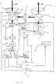
Fig. 2 illustrates the detailed structure of a distance
measuring apparatus according to an embodiment of the
invention. The oscillator 1 generates signals having, for
example, five different frequencies, namely, modulation
frequencies fT1, fT2 for the light source 3, a phase-detection
frequency f1F, and demodulation frequencies fR1 (which
equals fT1-f1F) and fR2 (which equals to fT2-f1F). The
modulation frequency fT1 is used for precise measurement of a
distance, and is set relatively high, e.g., 15MHz. The other
modulation frequency fT2 is used for rough measurement, and
is set relatively low, e.g., 75KHz. The two modulation
frequencies are selectively used according to a command
signal supplied from the CPU 2. The modulation frequencies fT1
and fT2 are supplied to the light source 3, and the
demodulation frequencies fR1 and fR2 are supplied to the light-receiving
unit 8.
With the higher modulation frequency fT1 of 15MHz light
goes and returns through the air for a distance of 10m within a
cycle. Accordingly, a distance less than the 10-meter range
can be accurately measured by precisely detecting the phase.
However, since one cycle of the 15MHz signal is 10m, there is no
distinction between 1m and 11m. The lower modulation
frequency fT2 therefore is simultaneously used for rough
measurement. Corresponding to these modulation
frequencies, two demodulation frequencies fR1 and fR2 are
provided.
Within the light source 3, the drive circuit 4 generates a
driving signal from the modulation frequency signal fTn to drive
the semiconductor laser diode 5. The semiconductor laser
diode 5 emits modulated light. The light emitted from the light
source 3 is shaped by the light-transmitting objective lens 6, and
guided to the object. The light is reflected by the object,
collected by the light-receiving objective lens 7, and enters the
light-receiving unit 8. As has been mentioned above, the light-receiving
unit 8 is a photoelectric converter which includes an
avalanche photodiode 9, a bias circuit 10 for the avalanche
photodiode 9, a filter 12 and an amplifier 13. A demodulation
frequency fRn selected by the CPU 2 is supplied from the
oscillator 1 to the bias circuit 10, and a bias voltage having that
demodulation frequency is applied to the avalanche
photodiode (APD) 9.
In general, the gain of an avalanche photodiode varies
in response to a bias voltage applied thereto. Accordingly,
when a demodulation frequency fRn is applied as a bias
voltage to the avalanche photodiode (APD) 9, the output of
the APD 9 has a phase-detection frequency component f1F
which is a difference (fTn-fRn) between the modulation
frequency fTn and the demodulation frequency fRn. The
output of the APD 9 maintains a phase difference of the
received signal. This operation is generally known as
heterodyne demodulation, which is used when converting the
frequency component of a high frequency signal to a low
frequency without disturbing the phase component. Through
this operation, the received rang-measuring signal becomes a
low frequency signal. The phase difference detector 20 will
detect a phase difference of the received signal in its low
frequency form which, in turn, facilitates phase detection while
maintaining high accuracy.
The photoelectrically converted signal is supplied from
the APD 9 to the filter 12 which extracts the range-measuring
frequency component of the electric signal. The electric signal
which has passed through the filter 12 is amplified by the
amplifier 13, and supplied to the gain control amplifier 14.
Meanwhile, the light beam emitted from the light source
3 is split by the splitter 15. The split light component is guided to
the light-receiving unit 8 through the light combining unit 17
along the reference optical path 16. An optical path switching
unit 18, which is constructed as, for example, a mechanical
shutter, is positioned before the light combining unit 17. The
optical path switching unit 18 selectively allows passage of
either the reference optical path or the range-measuring
optical path, and blocks the other, according to a command
signal from the CPU 2. A light intensity regulator 19 is provided
on the reference optical path 16. The light intensity regulator 19
controls the light intensity in the reference optical path based
on a command signal from the CPU 2, so that the light intensity
in the reference optical path becomes substantially equal to
the light intensity in the rang-measuring optical path. The light
intensity regulator may be of an ordinary mechanical type
having a mechanical drive for changing the angle between
two polarizers. However, as has been mentioned, it is
preferable to utilize a polarization control element, such as
liquid crystal, in the light intensity regulator, so that the light
transmissivity changes in response to a voltage (i.e., a control
signal) applied to the polarization control element. Other than
liquid crystal, a Kerr cell utilizing the Kerr effect or a Pockels cell
may be used to control the transmissivity according to a
voltage applied thereto.
The gain control amplifier 14 controls its gain according
to a control signal from the CPU 2. The gain control amplifier 14
appropriately amplifies the level of the input signal which has
been photoelectrically converted into an electric signal by the
light-receiving unit 8, and supplies the amplified signal to the
phase difference detector 20 through the phase shifter 22.
Although the dynamic range of the phase difference detector
20 is designed to be relatively narrow, the detection accuracy
is high because the electric signal is modified by the gain
control amplifier 14 so as to have a level within the dynamic
range of the phase difference detector 20. The light intensity
detector 21 determines the Intensity of the received (reflected)
light based on the output of the gain control amplifier 14. The
output of the light intensity detector 21 is supplied to the CPU 2
for gain adjustment. The CPU 2 supplies a gain control signal to
the gain control amplifier 14 according to the output signal
from the light intensity detector 21.
When the phase difference detector 20 receives the
received reflected signal that has been adjusted to a certain
level, the phase difference detector 20 detects a phase
difference a between the received signal and the transmitted
signal, having a range-measuring frequency f1F. Similarly, the
reference light received from the reference optical path is
amplified with a gain, and supplied to the phase difference
detector 20. The phase difference detector 20 detects a phase
difference b between the reference signal and the transmitted
signal with the frequency f1F. The distance from the object is
calculated by the CPU 2 according to formula (1). The
calculation result is displayed on the monitor 23.
The phase shifter is designed to appropriately take an
average of the detected phase difference values. If the phase
difference detected by the phase difference detector 20 is
around 0°, the detection result will become, for example, 0° or
364° depending on the detection error. In such a case, a
correct average cannot be obtained from multiple rounds of
phase difference detection. Therefore, the phase shifter 22 is
provided to shirt the detected phase by a certain degree as a
shifting amount, thereby avoiding an incorrect average
calculation. The phase shifter 22 subtracts the shifting amount
from the average. The shifting amount of the phase shifter 22 is
controlled by the CPU 2.
The operation of the distance measuring apparatus
shown in Fig. 2 will now be described. First, the gain control
amplifier 14 sets the level of a received signal. The optical path
switching unit 18 selects the range-measuring optical path 30B
according to a command from the CPU 2. The gain of the gain
control amplifier 14 is set to an appropriate value. The
modulation frequency and the demodulation frequency are
set to appropriate values in the oscillator 1. The selected
modulation frequency is supplied to the light source 3, and the
demodulation frequency is supplied to the light-receiving unit 8.
The semiconductor laser of the light source 3 emits a laser
beam having the selected modulation frequency toward the
object. The light-receiving unit 8 receives a reflected laser
beam from the object. The received beam is converted to an
electric signal, the level of which is measured by the light
intensity detector 21. The CPU 2 compares the level of the
electric signal with a predetermined optimum level of a
received signal, and changes the gain of the gain control
amplifier 14 so that the level of the electric signal becomes
most suitable to the phase difference detector 20.
Then, the optical path switching unit 18 selects the
reference optical path 16. The gain of the gain control
amplifier 14 maintains the same value. The CPU 2 changes the
attenuation amount of the light intensity regulator 19 so that the
light intensity from the reference optical path achieves an
optimal intensity level. As a result, the level of the reference
signal detected by the light intensity detector 21 is optimized.
After the gain of the gain control amplifier 14 and the
attenuation amount of the light intensity regulator 19 are
appropriately set, the phases of the signals from the range-measuring
optical path 30 and the reference optical path 16
are detected based on the modulation and demodulation
frequencies for precise measurement and the modulation and
demodulation frequencies for rough measurement. Using the
detection result, the distance from the object is calculated
according to formula (1).
In this arrangement, a range-measuring light and a
reference light which have optimum signal levels are supplied
to the phase difference detector 20. The phase difference
detector 20 can detect the phase difference based on the
optimum signal levels. Even if an inexpensive phase detector
with a relatively narrow dynamic range is used in the distance
measuring apparatus, a phase difference can be detected
with high accuracy. While the intensity of the reference light is
attenuated by the light intensity-regulator 19, the intensity of the
range-measuring light is not attenuated. Therefore, the
maximum measurable range and types of objects which are
subject to distance measurement are both maximized.
As has been described, a light intensity regulator is not
provided in the range-measuring optical path, and detection
of distances to a broad range of objects located at far
distances can be achieved. A light intensity regulator is
provided on the reference path to regulate the light intensity in
the reference optical path so that it matches the intensity of the
range-measuring light beam. The gain control amplifier adjusts
the level of a received signal to the optimum level suitable to
the phase difference detector. Thus, the measurement
accuracy is improved, while reducing the cost of the phase
difference detector. Moreover, liquid crystal is used in the light
intensity regulator to eliminate the need for a mechanical drive,
whereby light intensity is regulated quickly and precisely.
While the invention has been described by way of
exemplary embodiments, it is understood that the words which
have been used herein are words of description, rather than
words of limitation. Changes may be made, within the purview
of the appended claims, without departing from the scope and
the spirit of the invention in its broader aspects. Although the
invention has been described herein with reference to
particular structures, components, means, materials, and
embodiments, it is understood that the invention is not limited to
the particulars disclosed. The invention extends to all
equivalent structures, components, means, and uses such as
are properly within the scope of the appended claims.