EP0825376A2 - Pop top insertion indicator for thin walled connectors - Google Patents
Pop top insertion indicator for thin walled connectors Download PDFInfo
- Publication number
- EP0825376A2 EP0825376A2 EP97203171A EP97203171A EP0825376A2 EP 0825376 A2 EP0825376 A2 EP 0825376A2 EP 97203171 A EP97203171 A EP 97203171A EP 97203171 A EP97203171 A EP 97203171A EP 0825376 A2 EP0825376 A2 EP 0825376A2
- Authority
- EP
- European Patent Office
- Prior art keywords
- indicator
- housing
- connector
- quick connector
- indicator member
- Prior art date
- Legal status (The legal status is an assumption and is not a legal conclusion. Google has not performed a legal analysis and makes no representation as to the accuracy of the status listed.)
- Granted
Links
Images


Classifications
-
- F—MECHANICAL ENGINEERING; LIGHTING; HEATING; WEAPONS; BLASTING
- F16—ENGINEERING ELEMENTS AND UNITS; GENERAL MEASURES FOR PRODUCING AND MAINTAINING EFFECTIVE FUNCTIONING OF MACHINES OR INSTALLATIONS; THERMAL INSULATION IN GENERAL
- F16L—PIPES; JOINTS OR FITTINGS FOR PIPES; SUPPORTS FOR PIPES, CABLES OR PROTECTIVE TUBING; MEANS FOR THERMAL INSULATION IN GENERAL
- F16L37/00—Couplings of the quick-acting type
- F16L37/08—Couplings of the quick-acting type in which the connection between abutting or axially overlapping ends is maintained by locking members
- F16L37/084—Couplings of the quick-acting type in which the connection between abutting or axially overlapping ends is maintained by locking members combined with automatic locking
- F16L37/098—Couplings of the quick-acting type in which the connection between abutting or axially overlapping ends is maintained by locking members combined with automatic locking by means of flexible hooks
- F16L37/0985—Couplings of the quick-acting type in which the connection between abutting or axially overlapping ends is maintained by locking members combined with automatic locking by means of flexible hooks the flexible hook extending radially inwardly from an outer part and engaging a bead, recess or the like on an inner part
- F16L37/0987—Couplings of the quick-acting type in which the connection between abutting or axially overlapping ends is maintained by locking members combined with automatic locking by means of flexible hooks the flexible hook extending radially inwardly from an outer part and engaging a bead, recess or the like on an inner part the flexible hook being progressively compressed by axial tensile loads acting on the coupling
-
- F—MECHANICAL ENGINEERING; LIGHTING; HEATING; WEAPONS; BLASTING
- F16—ENGINEERING ELEMENTS AND UNITS; GENERAL MEASURES FOR PRODUCING AND MAINTAINING EFFECTIVE FUNCTIONING OF MACHINES OR INSTALLATIONS; THERMAL INSULATION IN GENERAL
- F16L—PIPES; JOINTS OR FITTINGS FOR PIPES; SUPPORTS FOR PIPES, CABLES OR PROTECTIVE TUBING; MEANS FOR THERMAL INSULATION IN GENERAL
- F16L37/00—Couplings of the quick-acting type
- F16L37/08—Couplings of the quick-acting type in which the connection between abutting or axially overlapping ends is maintained by locking members
- F16L37/084—Couplings of the quick-acting type in which the connection between abutting or axially overlapping ends is maintained by locking members combined with automatic locking
- F16L37/098—Couplings of the quick-acting type in which the connection between abutting or axially overlapping ends is maintained by locking members combined with automatic locking by means of flexible hooks
-
- F—MECHANICAL ENGINEERING; LIGHTING; HEATING; WEAPONS; BLASTING
- F16—ENGINEERING ELEMENTS AND UNITS; GENERAL MEASURES FOR PRODUCING AND MAINTAINING EFFECTIVE FUNCTIONING OF MACHINES OR INSTALLATIONS; THERMAL INSULATION IN GENERAL
- F16L—PIPES; JOINTS OR FITTINGS FOR PIPES; SUPPORTS FOR PIPES, CABLES OR PROTECTIVE TUBING; MEANS FOR THERMAL INSULATION IN GENERAL
- F16L2201/00—Special arrangements for pipe couplings
- F16L2201/10—Indicators for correct coupling
-
- Y—GENERAL TAGGING OF NEW TECHNOLOGICAL DEVELOPMENTS; GENERAL TAGGING OF CROSS-SECTIONAL TECHNOLOGIES SPANNING OVER SEVERAL SECTIONS OF THE IPC; TECHNICAL SUBJECTS COVERED BY FORMER USPC CROSS-REFERENCE ART COLLECTIONS [XRACs] AND DIGESTS
- Y10—TECHNICAL SUBJECTS COVERED BY FORMER USPC
- Y10S—TECHNICAL SUBJECTS COVERED BY FORMER USPC CROSS-REFERENCE ART COLLECTIONS [XRACs] AND DIGESTS
- Y10S285/00—Pipe joints or couplings
- Y10S285/921—Snap-fit
Definitions
- the present invention relates to quick connectors and, more particularly, to quick connectors having means enabling, by external inspection, determination of proper coupling between the male and female portions of the connector.
- This invention is related to United States Application No. 07/809,826, filed December 18, 1991, entitled “Retainer for Pop Top Indicator” having the same assignee of interest as this application.
- This invention is also related to United States Patent No. 5,178,424, issued Janaury 12, 1993, entitled “Pop -Off Quick Connect Indicator” having the same inventor and assignee of interest as this application.
- United States Serial No. 07/724,225 and United States Patent No. 5,178,424 are hereby incorporated within this specification by reference.
- a related problem stems from concomitant aspects of commercially available quick connect devices, namely: high volume and low sale price frequently necessitating the use of inexpensive, somewhat pliable materials, and complex contours of extremely small inter-fitting components. These aspects collectively increase the likelihood of mis-assembly.
- High volume production techniques, including automated assembly tends to aggravate the problem wherein mis-assembly or impermissible dimensional variations of the components is difficult to detect.
- the present invention provides a visual inspection device which enables, at a glance, the installer to ensure proper coupling of the connector.
- This invention also provides a visual inspection device adaptable to a variety of connectors.
- the present invention provides the art with a simple, inexpensive inspection device that overcomes the shortcomings of previous devices described above.
- the inventive quick connector includes a generally cylindrical connector housing defining an axial opening for matingly receiving a male member.
- Retainer means disposed substantially within the housing releasably interconnects the connector housing and male member.
- An insertion indicator also disposed partially within the housing is displaced axially upon interconnection of the connector housing and male member to provide a visual indication of the interconnection.
- index means axially and rotationally fix the insertion indicator relative to the connector housing.
- a quick connect insertion indicator designed in accordance with this invention includes a base member of generally annular configuration which is adapted for positioning about a male conduit within the connector housing.
- Two or more leg members extend axially from the base member and terminate near the opening.
- a generally annular indicator member which is positioned substantially adjacent to the opening is releasably engaged with the leg member terminations.
- means are provided operative to axially displace the base member upon engagement of the conduit and connector housing to effect separation of the base and indicator member.
- Guide means provide concentric positioning of the indicator member with the housing opening until coupling of the connector is complete.
- the insertion indicator includes an annular base member and two circumferentially spaced axially elongated leg members dimensioned such that the leg members terminate internally adjacent a step formed at the axial housing opening.
- Guide means are provided to maintain concentric positioning of the indicator member as least partially within the housing opening, the base member defining an abutment surface disposed to engage a mating abutment surface defined by the conduit to axially displace the base and leg members upon engagement of the conduit and connector housing to effect simultaneous separation of the base and indicator members.
- the insertion indicator defines axially elongated guide surfaces operative to engage axially elongated guide slots formed within an open cap that fits on the connector housing adjacent the opening to provide an axial freedom of relative displacement therebetween while prohibiting relative rotational displacement therebetween.
- This arrangement provides for precise positioning of the insertion indicator within the female housing to minimize the chance of mis-assembly or distortion of the components during coupling engagement.
- the slots and guide surfaces ensure that only desired relative axial displacement takes place during the engagement process and that rotation and skewing of the components will not occur.
- means for maintaining the indicator axially fixed relative to the female housing are provided.
- such means include radially extending projections formed on the axially elongated guide surfaces. The projections preferably cooperate with an abutment surface defined on the cap provided on the female housing.
- a small arcuate sector of the indicator member is removed, or, alternately, a rupture point is provided therein, preferably in conjunction with a generally planar tab member which is integrally formed with and radially extending from the indicator member.
- the base and leg members are formed integrally with the indicator member wherein either the indicator member or the leg members include predetermined weakened points, such as by reduced cross-sectional area that will simultaneously predictably fracture upon axial loading occasioned by coupling between the conduit and its mating connector housing.
- Figure 1 is a perspective exploded view of a conduit quirk connect assembly embodying the present invention.
- Figure 2 is a broken, cross-sectional view, on an enlarged scale, of a de-mated connector housing and male conduit.
- Figure 3 represents the connector housing and male conduit of Figure 2 in the coupled condition.
- Figure 4 is a cross-sectional view, on an enlarged scale, taken on lines IV-IV of Figure 2.
- Figure 5 is a quarter cross-sectional view of the female housing of Figure 2 taken from the top.
- Figure 6 is a top plan view of the preferred quick connect insertion indicator of the present invention.
- Figure 7 is a front plan view of the insertion indicator of Figure 6.
- Figure 8 is a side plan view of the insertion indicator of Figure 6.
- Figure 9 is a top plan view of a retainer employed with the present invention.
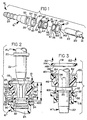
- Figure 10 is a cross-sectional view taken on lines X-X of Figure 9.
- Figure 11 is a front plan view of the retainer of Figure 9.
- Figure 12 is a top plan view of an alternative embodiment of the quick connect insertion indicator of the present invention.
- Figure 13 is a partial sectional view of a presently preferred embodiment of this invention as employed with a thin-walled connector.
- Figure 14 is a top plan view of the embodiment illustrated in Figure 13.
- Figure 15 is a partial sectional view of a second preferred embodiment of this invention as employed with a modified thin-walled connector.
- Figure 16 is a partial sectional view of a second preferred embodiment of this invention as employed with a modified thin-walled connector.
- the present invention includes an insertion indicator device, shown generally at 10, for use with a quick connector, shown generally at 12, including male and female elements 14 and 16, respectively, and a locking member or retainer 18.
- quick connector 12 is representative of known commercially available devices.
- the quick connector 12 illustrated herein is adapted for application within systems employing tubular conduit, although it is contemplated that the present invention could be employed with other structural configurations and applications.
- Male element 14 is illustrated as a thin wall metallic tube with an upset or external circumferential flange 20 integrally formed therein adjacent an open-end 22 adapted for insertion within a stepped through-passage 24 in female element 16.
- the end of female element 16 distal male element 14 has a series of external circumferential barbs 26 adapted for locking engagement with a resilient conduit (not illustrated).
- Locking member 18 is carried within an enlarged end 28 of female element 16 proximate male element 14 as will be described in greater detail hereinbelow.
- the through-passage 24 of female element 16 includes a stepped portion 30 within its enlarged end 28. Additional stepped portions may be provided to receive elements such as O-rings or the like (not illustrated) for sealing male element 14 within female element 16.
- retainer 18 comprises a generally annular base portion 32 nestingly disposed concentrically within through-passage 24 terminating in a radially outwardly extending flange portion 34 received within a step 36 formed in female element 16 opening into stepped portion 30 and co-acting therewith to define a seat 38.
- Four (4) extensions 40a-d are integrally formed with base portion 32 and are circumferentially equally spaced thereabout and extend axially therefrom towards an opening 42 defined by the end of female element 16 for receiving male element 14.
- Locking member 18 defines two (2) inwardly directed male element engaging fingers 44, 46 depending from adjoining pairs of free ends (40a,d and 40b,c) of extensions 40.
- Fingers 44, 46 define radially outwardly directed abutment surfaces 48, 50 formed thereon which lockingly engage with one of a pair of opposed radial openings 52, 54 formed in female element 16.
- the uppermost (in Figure 2), lateral surfaces of element 16 defining openings 52, 54 are designated as abutment surfaces 56, 58 which meetingly engage surfaces 48, 50 of retainer 18.
- the axially opposed ends of fingers 44, 46 define radially extending abutment surfaces 60, 62, which are, in assembly, axially spaced from seat 38 by a dimension "D" as will be described in detail hereinbelow.
- Fingers 44, 46 define radially inwardly tapered ramp surfaces 64, 66 extending through their axial length.
- Both female element 16 and retainer 18 are made of injection molded plastic or other suitable material. Quarter cross-sections are employed in Figure 5 for simplicity inasmuch as the structure is substantially symmetrical about the centerline axis A-A of female element 16. Lastly, certain interior components that typically would be employed with female element 16, such as sealing O-rings and spacers which normally would be disposed within through-passage 24, are deleted here for the sake of brevity.
- stepped portion 30 of female element 16 has complementary circumferentially opposed axially elongated guide grooves 70, 72 formed in the inner-diameter surface of end 28 and opening into through-passage 24.
- Grooves 70, 72 are rotationally positioned approximately 90 degrees offset from radial openings 52, 54.
- Laterally opposed side grooves 74, 76 straddle groove 70, extending axially through stepped portion 30 and opening into through-passage 24.
- side grooves 78, 80 are axially parallel to and straddle groove 72 and open radially into through-passage 24.
- Opening 42 defines a stepped annular groove 82 composed of an axial outwardly facing abutment surface 84 and radially outwardly diverging alignment surface 86.
- Indexing tabs 88, 90 integrally formed with flange portion 34 of base portion 32 extend radially outwardly therefrom and are dimensioned to slip-fit within guide grooves 70, 72.
- laterally spaced tangential indexing tabs 92, 94, 96, and 98 extend radially outwardly generally parallel to tabs 88, 90.
- Tabs 92 through 98 are, likewise, dimensioned to fit within their respective grooves 74 through 80.
- Flats or reliefs 100, 102 are formed in the circumferential wall of flange 34 in locations 90 degrees tangentially offset from tabs 88, 90 and are spaced radially inwardly of the inside diameter surface portion of end 28 which defines radial openings 52, 54 to ensure that flange 34 does not interfere with the use of an O.D. release tool as it penetrates openings 52, 54 to effect release of retainer 18 from female element 16.
- an O.D. release tool As best depicted in Figures 2 and 4, an O.D.
- release tool 166 shown in Figure 4 in phantom will radially depress fingers 44, 46 inwardly until the radially outermost edges of abutment surfaces 48, 50 are radially inwardly spaced from the innermost edges of abutment surfaces 56, 58 to effect release.
- Typical prior art retainers had a constant radius flange which could interfere with the axially innermost transverse surface 165 of tool 166 and prevent release.
- the local radial clearance 168 (designated R in Figure 4) provided by flats 100, 102 allows removal of retainer 18 with tool 166 still in place.
- the radially outer surfaces of flats 100, 102 are disposed substantially inwardly of the innermost radial edges of abutment surfaces 56, 58.
- Indicator device 10 is constructed integrally from injection molded plastic or other suitable material and includes a generally annular base member 112, two circumferentially opposed axially elongated leg members 114, 116 and a generally annular indicator member 118.
- Base member 112 has a characteristic outside diameter equal to or slightly less than the lateral spacing of flats 100, 102 to prevent interference with surface 165 of tool 166.
- Indicator member 188 has an approximately 90 degree circumferential section removed, rendering it U shaped, and defining a permanent opening between circumferential fingers 120, 122 which are spaced approximately one half of the diameter of male element 14 to ensure that after coupling, indicator member 118 remains engaged with its associated male element 14 until it is intentionally removed therefrom.
- the radially innermost surfaces of leg members 114, 116 are tangentially integrally joined with necks 115, 117 formed on the outer diameter circumferential surface 124 of base member 112 and extend radially outwardly therefrom.
- Leg members 114, 116 are generally rectangular in cross-section and define opposed radially outwardly facing guide surfaces 126, 128, as well as opposed lateral guide surfaces 130 through 136.
- Each leg member 114, 116 extends from base member 112 to an opposed end which is integrally formed with indicator member 118.
- the point of interface between leg members 114, 116 and indicator member 118 forms a necked region 138, 140 which are dimensioned identically to ensure as close as possible equal pull-apart strength.
- Indicator member 118 includes a generally rectangular recess 142 formed in the inner diameter surface 143 thereof. Indicator member 118 has a stepped typical cross-section defined by a rightwardly facing (as viewed in Figure 8) radially outwardly extending circumferential abutment surface 144 and a right-hand most inner abutment surface 146 interconnected by a circumferential tapered fillet 148.
- Quick connector 12 and indicator device 10 are provided with a system of guide surfaces which facilitates automated assembly and substantially reduces the likelihood of mis-assembly or component damage resulting from the assembly process.
- Grooves 70 through 80 interact with indexing, tabs 88 through 98 on retainer 18 as well as leg members 114, 116 of indicator device 10 to provide positive indexing therebetween to ensure against rotational mis-positioning.
- Multiple, laterally spaced sets of grooves 74, 70, 76 and 78, 72, 80 are provided to enhance the purchase of retainer 18 (via tabs 98, 90, 94 and 96, 88, 92, respectively) upon female element 16 to further reduce the likelihood of rotational mis-positioning by increasing the characteristic maximum chord dimension from the central axis.
- grooves 70 through 80 extend axially the entire length of end 22 of female element 16, they afford proper indexing of retainer 18 and indicator device 10 during the entire assembly process wherein retainer 18 and then indicator device 10 are sequentially axially inserted into female element 16 through opening 42.
- base portion 32 of retainer 18 abuts step 36 of female element 16 and abutment surfaces 48, 50 of engaging fingers 44, 46 resiliently expand into radial openings 52, 54 to provide a lock-fit therebetween.
- indicator device 10 Thereafter, as indicator device 10 is inserted, its base member 112 ramps axially along abutment surfaces 64, 66, momentarily resiliently displacing fingers 44, 46 radially outwardly until base member 112 is axially intermediate abutment surfaces 60, 62 and seat 38.
- indicator device 10 is positively retained within female element 16 by retainer element 18.
- Indicator device 10 insertion is complete when indicator member 118 surfaces 144, 146 and 148 abut female element 116 surfaces 83, 84 and 86, respectively.
- the radially extending surface of base member 112 facing abutment surfaces 60, 62 defines a seat for the leading edge of flange 120 of male element 14. It is thus, essential that dimension D as best seen in Figure 2, provide for tolerance stack-up of axial dimension of flange 20, base member 112 and base portion 32.
- Grooves 70, 72 are radially deep enough to substantially receive the section of leg members 112, 114 to ensure clearance for the insertion of male element 14 while maintaining axial freedom of movement of base member 112.
- indicator device 10 is illustrated in a first condition indicative of non-engagement between male and female elements 14 and 16.
- the leg members 114, 116 extend axially toward opening 42 to engage indicator member 118 such that abutment surface 144 of indicator member 118 abuts the upward most portion 83 (upward most as viewed in Figures 2 and 3) portion or transverse face 150 of female element 16.
- a substantial portion of indicator member 118 nests within groove 82 with abutment surface 146 abutting abutment surface 84 and alignment surface 86 following the contour of fillet 148 to effect a self-centering of indicator member 118 within opening 42.
- Leg members 114, 116 are provided with a characteristic length which, in the pre-coupling condition illustrated in Figure 2, suspends base member 112 axially from seat 38 of base portion 32 of retainer 18. Because surfaces 126 through 136 are in intimate sliding relationship with respect to grooves 170 through 180, base member 112 is secured from rotation or skewing prior to during and after the coupling process of quick connector 12.
- end portion 22 of male member 14 enters through-passage 24, passing through the inner-diameter of both indicator and base members 112 and 118 of indicator device 10 and base portion 32 of retainer 18.
- Flange 20 of male element 14 is dimensioned to axially ramp along surfaces 64, 66 of fingers 44, 46 until the trailing edge thereof passes abutment surfaces 60, 62, at which point fingers 44, 46 will resiliently snap radially inwardly to entrap flange 20 in its position as illustrated in Figure 3.
- the leading (lowermost) edge of abutment flange 20 contacts the upwardmost abutment surface of base member 112.
- the axial spacing (B-A) between the lowermost surface of base member 112 and the uppermost surface of seat 38 must be sufficient to accommodate a small degree of resiliency inherent in the material from which indicator device 10 is formed and ensure rupture at neck regions 138, 140.
- the tensional loading of leg members 114, 116 will cause a snap-back reaction as indicated by arrows 152, causing indicator member 118 to be actually ejected axially away from female element 16. Thereafter, it will be loosely retained on the portion of male element 14 leading away from the coupling in such a manner as to be clearly indicative of separation and thus a complete coupling has taken place.
- indicator member 118 can be removed by grasping it about its peripheral surface and resiliently distorting fingers 120, 122 for removal from male element 14.
- Recess 142 has a secondary function in that it creates a weakened or hinge point to enhance removal of indicator 25 member 118 from male element 14.
- an alternative embodiment of an indicator device 156 is illustrated which differs only in that an associated indicator member 154 is completely annular and is contemplated for applications where it may be desirable to allow it to permanently encircle male element 14 throughout the life cycle of the fitting.
- Indicator member 154 is provided with radial slits 156, 158 with only a thin section of web 160 remaining therebetween. If removal is desired, indicator member 154 can be removed by gripping it manually or with a tool and pulling radially away from male element 14, rupturing web 160 in the process. Removal is further enhanced by a provision of a generally planer finger tab 162 extending radially therefrom which is integrally formed with indicator member 154 of indicator device 153 and optionally provided with instructional indicia 164. The remainder of the construction of indicator device 153 is as described with reference to the embodiment illustrated in detail in Figures 6 through 8.
- Figures 13 through 16 illustrate an insertion indicator for thin-walled, metal tubing connectors at 200.
- Enlarged end 28 of female housing member 202 is appropriately fitted with cap 204 adjacent the transverse face 206 of female member 202.
- Indicator member 210 is appropriately positioned within cap 204 as shall be described in further detail below.
- Thin-walled connector 202 is preferably metallic.
- Thin-wall connector 202 is typical of the connectors described in U.S. Patent No. 5,135,268 with the exceptions noted below and U.S. Patent No. 5,135,268 is hereby incorporated by reference into this specification.
- the inventive cap 204 makes indicator member 210 adaptable to thin-walled connectors.
- Cap 204 is preferably made of injection molded plastic or other suitable similar material.
- Indicator member 210 is preferably designed in accordance with the teachings noted above in reference to Figures 1-12. Some changes or additions are preferably made to indicator member 210 relative to indicator member 10 described above.
- Cap 204 provides the ability to nest indicator member 210 within the shoulder 212 defined within cap 204.
- Indicator member 210 is retained substantially within cap 204 and female housing member 202.
- Cap 204 includes bearing surface 214 which bears against abutment surface 216 defined on indicator member 210.
- Circumferential surface 218 within cap 204 has an inner diameter slightly greater than the outer diameter of the generally annular indicator 220.
- abutment surface 216 and bearing surface 214 are preferably long enough such that insertion of a male member into female housing 202 in accordance with the general teachings described above in relation to Figures 1-12 will not allow deformation of generally annular indicator 220 such that it protrudes inwardly into female housing element 202 but rather that proper insertion indication will be achieved as described generally above.
- Indicator member 210 is designed as indicator member 10 described above in relation to Figures 1-12.
- An addition added in the preferred embodiment illustrated in Figures 13 through 16 includes radial projections 226 and 228 on leg members 222 and 224, respectively. Radial projections 226 and 228 cooperate with abutment surface 230 defined on cap 204 to maintain indicator member 210 axially fixed relative to cap 204 and housing member 202.
- Indicator member 210 is maintained rotationally fixed relative to cap 204 and housing member 202 because legs 222 and 224 are interdigitated with a retainer as described below. Alternatively, relative rotational movement is prohibited by inserting legs 222 and 224 into axially extending grooves provided in one embodiment of cap 204 along the inner circumferential surface thereof. Such grooves in cap 204 serve the same rotationally fixing function as grooves 70 and 72 described previously.
- Tapered lip 232 is provided adjacent abutment surface 230 to provide ease of attachment of cap 204 to female housing member 202.
- Cap 204 is preferably generally annular having a furthest outer diameter being the same as the furthest outer diameter of the enlarged end 28 of female housing member 202.
- Insertion indicator 210 can then be applied to thin-walled connector 202 by manipulating indicator 210 into (downward according to the drawing) cap 204 and housing member 202 sufficiently until radially extending ribs 226 and 228 are properly engaged by abutment surface 230 and generally annular indicator 220 is properly nested within shoulder 212 such that bearing surface 214 is resting against abutment surface 216.
- assembly 200 is properly configured and ready for insertion of a male member into thin-walled connector 202.
- indicator member 210 is provided with necked regions 238 and 239 on legs 222 and 224, respectively, which are preferably dimensioned identically to insure as close as possible equal pull-apart strength.
- the manner of operation of indicator member 210 parallels that of indicator 10 as described above.
- Thin-walled connector 202 is preferably provided with a stainless steel retainer 241 that serves as retaining means for retaining male connector member 240 (shown in phantom) within thin-walled connector 202.
- a stainless steel retainer 241 that serves as retaining means for retaining male connector member 240 (shown in phantom) within thin-walled connector 202.
- Proper insertion of male conduit 240 causes bead 242 to ramp along radially inwardly extending finger-like projections or retainer 241 until they snap radially inwardly to engage and bear against an upper (according to the drawing) surface on the bead 242 on male member 240 in a manner similar to that described above ( Figures 2 and 3).
- Legs 222 and 224 on indicator 210 are placed between pairs of the finger-like projections on retainer 241. This interdigitation helps to prohibit relative rotational displacement between indicator 210 and housing 202.
- Figures 15 and 16 show further embodiments of a thin-walled connector employing a modified version of the inventive cap 204.
- flange 234 is provided by effectively bending over the edge of thin-walled connector 202 such that leg 248 protrudes inward into thin-walled connector 202 and runs generally parallel to the outer surface of the connector member.
- the extended length of leg 248 compared to the flange 234 provided in Figure 13 provides added pull-out strength for maintaining cap 204 in proper engagement with thin-walled housing 202.
- the particular embodiment illustrated in Figure 16 includes a leg 248 that is long enough such that cap 204 must be modified in order to properly retain insertion indicator 210 such that it is substantially disposed within cap 204 and female housing 202.
- leg 248 and, therefore, cap 204 necessitates a recess 250 which is a generally radially defined groove or notch within the inner wall of cap 204 that cooperates with radially extending projections 226 and 228 on legs 222 and 224 of insertion indicator 210, respectively.
- recess 250 is a generally radially defined groove or notch within the inner wall of cap 204 that cooperates with radially extending projections 226 and 228 on legs 222 and 224 of insertion indicator 210, respectively.
- leg 248 on thin-walled connector 202 will not be so long as to require a notch 250 to be formed within cap 204.
- leg 248 has an axial length that allows cap 204 to be provided such that radially extending projections or ribs 226 and 228 cooperate with an abutment surface 230.
- insertion indicator 210 relative to the embodiment illustrated in Figures 15 and 16 parallels that described above in relation to Figures 1-12 and 13-14 in order to ensure accurate indication of proper coupling between a male member and thin-walled connector 202.
- leg members 114, 116 could terminate in a snap-apart, reusable fitting such as described in United States Patent No. 5,178,424. Accordingly, the foregoing is not to be construed in a limiting sense.
Abstract
Description
Claims (8)
- A quick connector, comprising a generally cylindrical connector housing (16,202) defining an axial opening for matingly receiving a male member (14,240), retainer means (18,241) disposed at least substantially within the housing for releasably interconnecting the connector housing and the male member, and an indicator member (118,220) the indicator member being axially displaceable in response to proper interconnection of the connector housing and the male member to provide a visual indication of the interconnection, the connector housing being provided with means defining an abutment surface (216) disposed adjacent the axial opening for abutment against the indicator member, and the quick connector being characterised in that the connector housing is provided with means defining an axially extending generally annular surface (218) disposed adjacent the abutment surface defining a shoulder which receives and nests the indicator member such that the indicator member is disposed substantially within the shoulder.
- A quick connector as claimed in claim 1, wherein the largest diameter portion of the indicator member is contained in the shoulder.
- A quick connector as claimed in claim 1 or claim 2, wherein the indicator member does not project axially out of the axial opening.
- A quick connector as claimed in any preceding claim, further comprising a base member (112,236) which is generally annular and is adapted for positioning about the male member within the housing, a plurality of circumferentially spaced, axially extending elongate leg members (114,116,222,224) being provided which terminate internally adjacent the axial housing opening, the indicator member being generally annular and releasably engaging the leg member terminations, the quick connector further comprising guide means for maintaining concentric positioning of the indicator member with the housing, the base member defining an abutment surface disposed to engage a mating abutment surface defined by the male member to axially displace the base and leg members upon interconnection of the male member and the housing to effect substantially simultaneous separation of the base and indicator members.
- A quick connector as claimed in claim 4, wherein the base member has an outside diameter dimensioned less than the inside diameter dimension of the housing opening and an inside diameter dimensioned slightly greater than the nominal outside diameter dimension of the male member abutment surface.
- A quick connector as claimed in claim 4 or claim 5, wherein the indicator member has an inside diameter dimensioned slightly greater than the outside diameter dimension of the male member abutment surface.
- A quick connector as claimed in any of claims 4 to 6, wherein the indicator member is integrally formed with the base and leg members and the leg members include a predetermined weakened point (138,140,238,239) operative to predictably fracture under axial loading to effect the separation.
- A quick connector as claimed in any preceding claim, wherein the insertion indicator further comprises means (228) for limiting relative axial movement between the housing and the indicator.
Applications Claiming Priority (3)
| Application Number | Priority Date | Filing Date | Title |
|---|---|---|---|
| US126280 | 1993-09-24 | ||
| US08/126,280 US5425556A (en) | 1993-09-24 | 1993-09-24 | Pop top insertion indicator for thin walled connectors |
| EP94928081A EP0712473B1 (en) | 1993-09-24 | 1994-09-12 | Pop top insertion indicator for thin walled connectors |
Related Parent Applications (1)
| Application Number | Title | Priority Date | Filing Date |
|---|---|---|---|
| EP94928081A Division EP0712473B1 (en) | 1993-09-24 | 1994-09-12 | Pop top insertion indicator for thin walled connectors |
Publications (3)
| Publication Number | Publication Date |
|---|---|
| EP0825376A2 true EP0825376A2 (en) | 1998-02-25 |
| EP0825376A3 EP0825376A3 (en) | 2000-01-05 |
| EP0825376B1 EP0825376B1 (en) | 2002-04-10 |
Family
ID=22423970
Family Applications (2)
| Application Number | Title | Priority Date | Filing Date |
|---|---|---|---|
| EP97203171A Expired - Lifetime EP0825376B1 (en) | 1993-09-24 | 1994-09-12 | Pop top insertion indicator for thin walled connectors |
| EP94928081A Expired - Lifetime EP0712473B1 (en) | 1993-09-24 | 1994-09-12 | Pop top insertion indicator for thin walled connectors |
Family Applications After (1)
| Application Number | Title | Priority Date | Filing Date |
|---|---|---|---|
| EP94928081A Expired - Lifetime EP0712473B1 (en) | 1993-09-24 | 1994-09-12 | Pop top insertion indicator for thin walled connectors |
Country Status (5)
| Country | Link |
|---|---|
| US (2) | US5425556A (en) |
| EP (2) | EP0825376B1 (en) |
| AT (2) | ATE216046T1 (en) |
| DE (2) | DE69415160T2 (en) |
| WO (1) | WO1995008733A1 (en) |
Cited By (1)
| Publication number | Priority date | Publication date | Assignee | Title |
|---|---|---|---|---|
| WO2008059490A1 (en) * | 2006-11-13 | 2008-05-22 | Elgo Irrigation Ltd. | Safety lock for quick fit connector |
Families Citing this family (23)
| Publication number | Priority date | Publication date | Assignee | Title |
|---|---|---|---|---|
| US5794984A (en) * | 1993-11-16 | 1998-08-18 | Proprietary Technology, Inc. | Quick connector |
| US5785358A (en) * | 1994-09-26 | 1998-07-28 | Bundy Corporation | Connection verifier for a quick connector coupling |
| US5551732A (en) * | 1995-02-14 | 1996-09-03 | Proprietary Technology, Inc. | Quick connector |
| KR19980703387A (en) * | 1995-03-27 | 1998-10-15 | 도날드 디. 바쏠로뮤 | Quick connector with ring to confirm proper connection |
| US6234544B1 (en) | 1995-09-26 | 2001-05-22 | Proprietary Technology, Inc. | Quick connector with confirmation feature |
| US5779278A (en) * | 1995-12-27 | 1998-07-14 | Itt Automotive, Inc. | Pop off insertion indicator for metal quick connectors |
| BR9601539A (en) * | 1996-04-12 | 2004-06-29 | Tampas Click Ltda | Mounting and connecting indicator for fuel or general fluid lines |
| US6170886B1 (en) | 1996-05-14 | 2001-01-09 | Proprietary Technology, Inc. | Quick connector |
| WO1998022743A1 (en) * | 1996-11-20 | 1998-05-28 | Proprietary Technology, Inc. | Quick connector with visual indicator |
| DE19804958A1 (en) | 1998-02-07 | 1999-08-12 | Itt Mfg Enterprises Inc | Evaluation concept for distance measuring methods |
| US6062607A (en) * | 1998-07-17 | 2000-05-16 | Proprietary Technology, Inc. | Quick connector with secondary latch confirming feature |
| US6543814B2 (en) | 2000-08-10 | 2003-04-08 | John M. Bartholomew | Quick connector |
| FR2818731B1 (en) * | 2000-12-22 | 2006-11-03 | Legris Sa | FAST COUPLER WITH CONNECTION LAMP |
| US6810569B1 (en) | 2003-07-08 | 2004-11-02 | Visteon Global Technologies, Inc. | Workpiece release with computer verified connections |
| US20060108705A1 (en) * | 2004-11-23 | 2006-05-25 | Rowley William W | Method for injection molding component fittings on extrudates |
| US7712319B2 (en) * | 2004-12-27 | 2010-05-11 | Carrier Corporation | Refrigerant charge adequacy gauge |
| US7971912B2 (en) * | 2005-04-07 | 2011-07-05 | Sanoh Kogyo Kabushiki Kaisha | Quick connector |
| DE102005060135A1 (en) * | 2005-12-16 | 2007-07-05 | A. Raymond Et Cie | Coupling for connecting the ends of two pipes in a fluid pipe system has securing part with substantially closed annular sleeve with latching part(s) and locking piece(s) mounted on side of annular sleeve by radially sprung spring bridges |
| FR2919372B1 (en) | 2007-07-25 | 2013-05-10 | Legris Sa | LIGHTING CONNECTION. |
| US7950700B2 (en) * | 2008-03-13 | 2011-05-31 | Paw Bioscience Products, Inc. | Connector assembly for sterile connectors |
| US8941731B2 (en) * | 2011-11-22 | 2015-01-27 | Hitachi Automotive Systems Americas, Inc. | System and method to verify complete connection of two connectors |
| US10385999B2 (en) | 2015-07-09 | 2019-08-20 | Terumo Cardiovascular Systems Corporation | Fluid coupling devices |
| US10337656B2 (en) | 2015-10-27 | 2019-07-02 | Ford Global Technologies, Llc | Quick connect with visual indicator |
Citations (6)
| Publication number | Priority date | Publication date | Assignee | Title |
|---|---|---|---|---|
| US4925217A (en) | 1988-10-24 | 1990-05-15 | Huron Products Corporation | Quick connector with visual checking method |
| US5135268A (en) | 1990-11-08 | 1992-08-04 | Huron Products Industries | Quick connector |
| US5152555A (en) | 1991-03-26 | 1992-10-06 | Itt Corporation | Quick connect insertion indicator clip |
| US5178424A (en) | 1991-07-01 | 1993-01-12 | Itt Corporation | Pop-off quick connect indicator |
| US5226230A (en) | 1991-12-13 | 1993-07-13 | Itt Corporation | Universal o.d. release tool |
| US5297818A (en) | 1991-12-18 | 1994-03-29 | Itt Corporation | Retainer for pop-top indicator |
Family Cites Families (23)
| Publication number | Priority date | Publication date | Assignee | Title |
|---|---|---|---|---|
| US1692710A (en) * | 1925-02-25 | 1928-11-20 | John A Spahn | Conduit bushing |
| US3285627A (en) * | 1964-02-10 | 1966-11-15 | Weatherhead Co | Pipe coupling |
| US3796445A (en) * | 1971-12-29 | 1974-03-12 | Rimrock Enterprises Inc | Pipe saddle |
| GB1477306A (en) * | 1974-05-10 | 1977-06-22 | Hunter Plastic Ind Ltd | Inspection chamber assemblies |
| US4244608A (en) * | 1979-03-05 | 1981-01-13 | The Gates Rubber Company | Female coupling with staple lock |
| US4979765A (en) * | 1980-10-29 | 1990-12-25 | Proprietary Technology, Inc. | Swivelable quick connector assembly |
| US4753458A (en) * | 1986-08-28 | 1988-06-28 | Harvard Industries, Inc. | Quick connector assembly |
| US4783101A (en) * | 1987-05-20 | 1988-11-08 | Buell Industries, Inc. | Locking element |
| US4756558A (en) * | 1987-06-25 | 1988-07-12 | General Motors Corporation | Quick connect tube coupling |
| US4846506A (en) * | 1987-09-04 | 1989-07-11 | U.S. Plastics Corporation | Quick connect coupling |
| US4948176A (en) * | 1987-09-14 | 1990-08-14 | Proprietary Technology, Inc. | Swivelable quick connector assembly |
| US4793637A (en) * | 1987-09-14 | 1988-12-27 | Aeroquip Corporation | Tube connector with indicator and release |
| JPH01148191A (en) * | 1987-12-04 | 1989-06-09 | Nisshin Oil Mills Ltd:The | Production of substituent fat for cacao |
| DE3806404C2 (en) * | 1988-02-29 | 1994-06-09 | Raymond A Gmbh & Co Kg | Detachable connector for semi-rigid pipes |
| JP2691550B2 (en) * | 1988-03-01 | 1997-12-17 | 臼井国際産業株式会社 | Connector for small-diameter piping connection |
| JPH0538317Y2 (en) * | 1988-03-03 | 1993-09-28 | ||
| JP2588417B2 (en) * | 1988-03-05 | 1997-03-05 | 臼井国際産業株式会社 | Piping connector |
| JPH0538318Y2 (en) * | 1988-03-08 | 1993-09-28 | ||
| US5002315A (en) * | 1988-04-07 | 1991-03-26 | Proprietary Technology, Inc. | Quick connector |
| US5112084A (en) * | 1989-02-07 | 1992-05-12 | Usui Kokusai Sangyo Kaisha, Ltd. | Connector for small-diameter piping |
| US5069424A (en) * | 1990-10-17 | 1991-12-03 | Itt Corporation | Quick connector |
| US5226679A (en) * | 1991-05-16 | 1993-07-13 | Itt Corporation | Quick connect insertion indicator |
| US5228728A (en) * | 1991-12-17 | 1993-07-20 | Huron Products Industries, Inc. | Tube retainer release sleeve |
-
1993
- 1993-09-24 US US08/126,280 patent/US5425556A/en not_active Expired - Fee Related
-
1994
- 1994-09-12 AT AT97203171T patent/ATE216046T1/en not_active IP Right Cessation
- 1994-09-12 DE DE69415160T patent/DE69415160T2/en not_active Expired - Fee Related
- 1994-09-12 EP EP97203171A patent/EP0825376B1/en not_active Expired - Lifetime
- 1994-09-12 EP EP94928081A patent/EP0712473B1/en not_active Expired - Lifetime
- 1994-09-12 WO PCT/US1994/010242 patent/WO1995008733A1/en active IP Right Grant
- 1994-09-12 DE DE69430390T patent/DE69430390T2/en not_active Expired - Fee Related
- 1994-09-12 AT AT94928081T patent/ATE174415T1/en not_active IP Right Cessation
-
1995
- 1995-06-07 US US08/478,705 patent/US5676403A/en not_active Expired - Lifetime
Patent Citations (6)
| Publication number | Priority date | Publication date | Assignee | Title |
|---|---|---|---|---|
| US4925217A (en) | 1988-10-24 | 1990-05-15 | Huron Products Corporation | Quick connector with visual checking method |
| US5135268A (en) | 1990-11-08 | 1992-08-04 | Huron Products Industries | Quick connector |
| US5152555A (en) | 1991-03-26 | 1992-10-06 | Itt Corporation | Quick connect insertion indicator clip |
| US5178424A (en) | 1991-07-01 | 1993-01-12 | Itt Corporation | Pop-off quick connect indicator |
| US5226230A (en) | 1991-12-13 | 1993-07-13 | Itt Corporation | Universal o.d. release tool |
| US5297818A (en) | 1991-12-18 | 1994-03-29 | Itt Corporation | Retainer for pop-top indicator |
Cited By (1)
| Publication number | Priority date | Publication date | Assignee | Title |
|---|---|---|---|---|
| WO2008059490A1 (en) * | 2006-11-13 | 2008-05-22 | Elgo Irrigation Ltd. | Safety lock for quick fit connector |
Also Published As
| Publication number | Publication date |
|---|---|
| DE69430390D1 (en) | 2002-05-16 |
| WO1995008733A1 (en) | 1995-03-30 |
| US5676403A (en) | 1997-10-14 |
| EP0712473B1 (en) | 1998-12-09 |
| DE69430390T2 (en) | 2002-08-14 |
| ATE174415T1 (en) | 1998-12-15 |
| DE69415160T2 (en) | 1999-08-12 |
| EP0712473A1 (en) | 1996-05-22 |
| US5425556A (en) | 1995-06-20 |
| EP0825376B1 (en) | 2002-04-10 |
| ATE216046T1 (en) | 2002-04-15 |
| DE69415160D1 (en) | 1999-01-21 |
| EP0825376A3 (en) | 2000-01-05 |
Similar Documents
| Publication | Publication Date | Title |
|---|---|---|
| EP0825376B1 (en) | Pop top insertion indicator for thin walled connectors | |
| US5297818A (en) | Retainer for pop-top indicator | |
| EP0720711B1 (en) | Quick connector housing with elongated barb design | |
| US5178424A (en) | Pop-off quick connect indicator | |
| US5226679A (en) | Quick connect insertion indicator | |
| US5813705A (en) | Snap-action pipe coupling retainer | |
| US5152555A (en) | Quick connect insertion indicator clip | |
| US4637640A (en) | Push-in connect fitting | |
| EP0722554B1 (en) | Quick connect stuffer pin | |
| KR100246176B1 (en) | Positive transition quick connect coupling | |
| CA1250333A (en) | Hose coupling | |
| US5893590A (en) | Quick connector housing with elongated barb design to prevent accidental engagement | |
| AU2007240189A1 (en) | Improvements in or relating to tube couplings | |
| WO1999027290A1 (en) | Pipe connections | |
| PL183366B1 (en) | Press-fit pipe unions | |
| JPH0451715B2 (en) | ||
| US5779278A (en) | Pop off insertion indicator for metal quick connectors | |
| US5455995A (en) | Tool for uncoupling quick connect tubular couplings | |
| EP0775279A2 (en) | Quick connector housing with elongated barb design | |
| EP0975912A1 (en) | "pop off" insertion indicator for metal quick connectors | |
| WO1995000793A1 (en) | Quick-connect tubing coupling |
Legal Events
| Date | Code | Title | Description |
|---|---|---|---|
| PUAI | Public reference made under article 153(3) epc to a published international application that has entered the european phase |
Free format text: ORIGINAL CODE: 0009012 |
|
| 17P | Request for examination filed |
Effective date: 19971013 |
|
| AC | Divisional application: reference to earlier application |
Ref document number: 712473 Country of ref document: EP |
|
| AK | Designated contracting states |
Kind code of ref document: A2 Designated state(s): AT BE CH DE DK ES FR GB GR IE IT LI LU MC NL PT SE |
|
| RIN1 | Information on inventor provided before grant (corrected) |
Inventor name: SZABO, GEORGE |
|
| PUAL | Search report despatched |
Free format text: ORIGINAL CODE: 0009013 |
|
| AK | Designated contracting states |
Kind code of ref document: A3 Designated state(s): AT BE CH DE DK ES FR GB GR IE IT LI LU MC NL PT SE |
|
| 17Q | First examination report despatched |
Effective date: 20001020 |
|
| GRAG | Despatch of communication of intention to grant |
Free format text: ORIGINAL CODE: EPIDOS AGRA |
|
| GRAG | Despatch of communication of intention to grant |
Free format text: ORIGINAL CODE: EPIDOS AGRA |
|
| GRAH | Despatch of communication of intention to grant a patent |
Free format text: ORIGINAL CODE: EPIDOS IGRA |
|
| RAP1 | Party data changed (applicant data changed or rights of an application transferred) |
Owner name: ITT MANUFACTURING ENTERPRISES, INC. |
|
| REG | Reference to a national code |
Ref country code: GB Ref legal event code: IF02 |
|
| GRAH | Despatch of communication of intention to grant a patent |
Free format text: ORIGINAL CODE: EPIDOS IGRA |
|
| GRAA | (expected) grant |
Free format text: ORIGINAL CODE: 0009210 |
|
| AC | Divisional application: reference to earlier application |
Ref document number: 712473 Country of ref document: EP |
|
| AK | Designated contracting states |
Kind code of ref document: B1 Designated state(s): AT BE CH DE DK ES FR GB GR IE IT LI LU MC NL PT SE |
|
| PG25 | Lapsed in a contracting state [announced via postgrant information from national office to epo] |
Ref country code: NL Free format text: LAPSE BECAUSE OF FAILURE TO SUBMIT A TRANSLATION OF THE DESCRIPTION OR TO PAY THE FEE WITHIN THE PRESCRIBED TIME-LIMIT Effective date: 20020410 Ref country code: LI Free format text: LAPSE BECAUSE OF FAILURE TO SUBMIT A TRANSLATION OF THE DESCRIPTION OR TO PAY THE FEE WITHIN THE PRESCRIBED TIME-LIMIT Effective date: 20020410 Ref country code: IT Free format text: LAPSE BECAUSE OF FAILURE TO SUBMIT A TRANSLATION OF THE DESCRIPTION OR TO PAY THE FEE WITHIN THE PRE;WARNING: LAPSES OF ITALIAN PATENTS WITH EFFECTIVE DATE BEFORE 2007 MAY HAVE OCCURRED AT ANY TIME BEFORE 2007. THE CORRECT EFFECTIVE DATE MAY BE DIFFERENT FROM THE ONE RECORDED.SCRIBED TIME-LIMIT Effective date: 20020410 Ref country code: GR Free format text: LAPSE BECAUSE OF FAILURE TO SUBMIT A TRANSLATION OF THE DESCRIPTION OR TO PAY THE FEE WITHIN THE PRESCRIBED TIME-LIMIT Effective date: 20020410 Ref country code: CH Free format text: LAPSE BECAUSE OF FAILURE TO SUBMIT A TRANSLATION OF THE DESCRIPTION OR TO PAY THE FEE WITHIN THE PRESCRIBED TIME-LIMIT Effective date: 20020410 Ref country code: BE Free format text: LAPSE BECAUSE OF FAILURE TO SUBMIT A TRANSLATION OF THE DESCRIPTION OR TO PAY THE FEE WITHIN THE PRESCRIBED TIME-LIMIT Effective date: 20020410 Ref country code: AT Free format text: LAPSE BECAUSE OF FAILURE TO SUBMIT A TRANSLATION OF THE DESCRIPTION OR TO PAY THE FEE WITHIN THE PRESCRIBED TIME-LIMIT Effective date: 20020410 |
|
| REF | Corresponds to: |
Ref document number: 216046 Country of ref document: AT Date of ref document: 20020415 Kind code of ref document: T |
|
| REG | Reference to a national code |
Ref country code: CH Ref legal event code: EP |
|
| REG | Reference to a national code |
Ref country code: IE Ref legal event code: FG4D |
|
| REF | Corresponds to: |
Ref document number: 69430390 Country of ref document: DE Date of ref document: 20020516 |
|
| PG25 | Lapsed in a contracting state [announced via postgrant information from national office to epo] |
Ref country code: SE Free format text: LAPSE BECAUSE OF FAILURE TO SUBMIT A TRANSLATION OF THE DESCRIPTION OR TO PAY THE FEE WITHIN THE PRESCRIBED TIME-LIMIT Effective date: 20020710 Ref country code: PT Free format text: LAPSE BECAUSE OF FAILURE TO SUBMIT A TRANSLATION OF THE DESCRIPTION OR TO PAY THE FEE WITHIN THE PRESCRIBED TIME-LIMIT Effective date: 20020710 Ref country code: DK Free format text: LAPSE BECAUSE OF FAILURE TO SUBMIT A TRANSLATION OF THE DESCRIPTION OR TO PAY THE FEE WITHIN THE PRESCRIBED TIME-LIMIT Effective date: 20020710 |
|
| ET | Fr: translation filed | ||
| PGFP | Annual fee paid to national office [announced via postgrant information from national office to epo] |
Ref country code: DK Payment date: 20020821 Year of fee payment: 9 |
|
| PGFP | Annual fee paid to national office [announced via postgrant information from national office to epo] |
Ref country code: MC Payment date: 20020826 Year of fee payment: 9 |
|
| PGFP | Annual fee paid to national office [announced via postgrant information from national office to epo] |
Ref country code: LU Payment date: 20020828 Year of fee payment: 9 |
|
| NLV1 | Nl: lapsed or annulled due to failure to fulfill the requirements of art. 29p and 29m of the patents act | ||
| PGFP | Annual fee paid to national office [announced via postgrant information from national office to epo] |
Ref country code: IE Payment date: 20020926 Year of fee payment: 9 |
|
| REG | Reference to a national code |
Ref country code: CH Ref legal event code: PL |
|
| PG25 | Lapsed in a contracting state [announced via postgrant information from national office to epo] |
Ref country code: ES Free format text: LAPSE BECAUSE OF FAILURE TO SUBMIT A TRANSLATION OF THE DESCRIPTION OR TO PAY THE FEE WITHIN THE PRESCRIBED TIME-LIMIT Effective date: 20021030 |
|
| PLBE | No opposition filed within time limit |
Free format text: ORIGINAL CODE: 0009261 |
|
| STAA | Information on the status of an ep patent application or granted ep patent |
Free format text: STATUS: NO OPPOSITION FILED WITHIN TIME LIMIT |
|
| 26N | No opposition filed |
Effective date: 20030113 |
|
| PG25 | Lapsed in a contracting state [announced via postgrant information from national office to epo] |
Ref country code: LU Free format text: LAPSE BECAUSE OF NON-PAYMENT OF DUE FEES Effective date: 20030912 Ref country code: IE Free format text: LAPSE BECAUSE OF NON-PAYMENT OF DUE FEES Effective date: 20030912 |
|
| PG25 | Lapsed in a contracting state [announced via postgrant information from national office to epo] |
Ref country code: MC Free format text: LAPSE BECAUSE OF NON-PAYMENT OF DUE FEES Effective date: 20030930 |
|
| REG | Reference to a national code |
Ref country code: IE Ref legal event code: MM4A |
|
| PGFP | Annual fee paid to national office [announced via postgrant information from national office to epo] |
Ref country code: DE Payment date: 20041102 Year of fee payment: 11 |
|
| PGFP | Annual fee paid to national office [announced via postgrant information from national office to epo] |
Ref country code: GB Payment date: 20050908 Year of fee payment: 12 |
|
| PGFP | Annual fee paid to national office [announced via postgrant information from national office to epo] |
Ref country code: FR Payment date: 20050919 Year of fee payment: 12 |
|
| PG25 | Lapsed in a contracting state [announced via postgrant information from national office to epo] |
Ref country code: DE Free format text: LAPSE BECAUSE OF NON-PAYMENT OF DUE FEES Effective date: 20060401 |
|
| GBPC | Gb: european patent ceased through non-payment of renewal fee |
Effective date: 20060912 |
|
| REG | Reference to a national code |
Ref country code: FR Ref legal event code: ST Effective date: 20070531 |
|
| PG25 | Lapsed in a contracting state [announced via postgrant information from national office to epo] |
Ref country code: GB Free format text: LAPSE BECAUSE OF NON-PAYMENT OF DUE FEES Effective date: 20060912 |
|
| PG25 | Lapsed in a contracting state [announced via postgrant information from national office to epo] |
Ref country code: FR Free format text: LAPSE BECAUSE OF NON-PAYMENT OF DUE FEES Effective date: 20061002 |