EP0827333A2 - Method and apparatus for creating a continuous tone image from a halftone image - Google Patents
Method and apparatus for creating a continuous tone image from a halftone image Download PDFInfo
- Publication number
- EP0827333A2 EP0827333A2 EP97306400A EP97306400A EP0827333A2 EP 0827333 A2 EP0827333 A2 EP 0827333A2 EP 97306400 A EP97306400 A EP 97306400A EP 97306400 A EP97306400 A EP 97306400A EP 0827333 A2 EP0827333 A2 EP 0827333A2
- Authority
- EP
- European Patent Office
- Prior art keywords
- image
- subband
- images
- halftone
- continuous tone
- Prior art date
- Legal status (The legal status is an assumption and is not a legal conclusion. Google has not performed a legal analysis and makes no representation as to the accuracy of the status listed.)
- Granted
Links
Images


Classifications
-
- H—ELECTRICITY
- H04—ELECTRIC COMMUNICATION TECHNIQUE
- H04N—PICTORIAL COMMUNICATION, e.g. TELEVISION
- H04N1/00—Scanning, transmission or reproduction of documents or the like, e.g. facsimile transmission; Details thereof
- H04N1/40—Picture signal circuits
- H04N1/40075—Descreening, i.e. converting a halftone signal into a corresponding continuous-tone signal; Rescreening, i.e. combined descreening and halftoning
Definitions
- This invention relates to methods and apparatus for converting a halftone image generated from an original continuous tone image back into a continuous tone image.
- Halftoning refers to generating a binary, or two-tone, image from a continuous tone, or contone or grayscale, image.
- grayscale images refer to continuous tone black (or some other single color) and white images
- contone images can be either full color images or single-color and white images.
- a halftone image is generated from a contone (full color or grayscale) image using any one of a variety of halftoning techniques. These various techniques include: 1) threshold arrays or dithering, such as clustered dots, dispersed dots and stochastic screens; 2) adaptive processes, such as error diffusion; and 3) interactive processes, such as least squares and direct binary search. It should be appreciated that this list is not exhaustive.
- halftoning is a many-to-one process. That is, regardless of the particular halftoning technique used, many variations of the original contone image will result in the same halftone image.
- Unscreening refers to the process for "undoing" the halftoning of an original contone image. More precisely, unscreening refers to creating a contone image from an original halftone image. Because halftoning is a many-to-one process, unscreening is generally a one-to-many process. That is, any one of a number of variations of the resulting contone image can be created by the unscreening process from the original halftone image.
- the goal of unscreening is thus to generate an unscreened contone image which most closely approximates the original contone image from which the original halftone image was itself created.
- Previous unscreening techniques have therefore been developed based on the particular halftone techniques used to create the original halftone images. That is, each previous unscreening technique was designed specifically to unscreen a halftone image created using a particular halftone technique.
- the MAP projection unscreening technique disclosed by Wong, in Algorithms 2 and 3 on pages 494 and 496, respectively is able to unscreen an error-diffused halftone image without any a priori knowledge of the error diffusion kernel used to create the error-diffused halftone image.
- the MAP projection unscreening technique assumes that halftone image has been formed by error diffusion.
- a system which implements the MAP projection unscreening technique must either be supplied only with error-diffused halftone images or include a gatekeeper for rejecting any non-error-diffused halftone images.
- each of the unscreening techniques disclosed in these papers operate in the spatial domain and use low-pass filtering with various ones of impulse removal (Miceli), logic filtering (Fan), projection on convex sets (Analoui) and successive approximation (Analoui and Kern).
- unscreening techniques outlined above operate based on the spatial distribution of the binary halftone values.
- One practical use of unscreening is to recover an electronic contone image from an electronic halftone image obtained by scanning a printed halftone image of a document, such as a newspaper, a magazine or a book. In this case, the halftone image has been scanned to create the electronic halftone image.
- the scanner spatially filters the halftone image when creating the electronic halftone image.
- the unscreening technique must distinguish or otherwise separate the halftone values resulting from the halftoning process from the values resulting from spatially filtering the halftone image during scanning.
- the present invention provides a method and apparatus for creating a continuous tone image from a halftone image as defined in the appended claims.
- the invention further provides an unscreening method and apparatus for unscreening an arbitrary halftone image independently of whether the halftone image has been scanned.
- the invention thus provides a wavelet-based universal unscreening method and apparatus.
- the invention further provides a method and apparatus for selectively processing a halftone image using a series of spatial and frequency filters which preserves most of the original image content while eliminating halftone noise.
- the invention additionally provides a method and apparatus for non-linearly filtering the resulting contone image to create a final contone image.
- This invention still further provides a method and apparatus which is independent of parameter estimation and is thus universal to all types of halftoned images, including scanned halftoned images.
- the method of this invention includes:
- the decomposing step of the method of this invention includes decomposing the original halftone image into a plurality of different frequency subband images based on a discrete wavelet transform.
- the decomposing step additionally includes decomposing one of the plurality of upper level different frequency subband images into a plurality of lower level different frequency subband images, and repeating the upper level subband image decomposing step a plurality of times.
- the noise-attenuating step includes clipping the magnitudes of the pixels of the high frequency subband images of each level, and further includes weighing the magnitudes of the parent subband image for each level of subband images and clipping the magnitudes of the high frequency subband images to at most the weighted magnitude of their parent band. Furthermore, the weighing varies from level to level. Additionally, the clipping step is adaptive to edges in the high frequency subband images.
- the oriented filtering step includes applying a one-dimensional low-pass filter along an orientation of each subband image.
- a horizontal low-pass filter is applied to the vertical subband images
- a vertical low-pass filter is applied to the horizontal subband images
- a X-shaped low-pass filter is applied to the diagonal subband images.
- the oriented filtering step further includes adapting the filtering to the resolution of the subband images.
- the oriented filtering step additionally includes selecting appropriate filters based on estimates of the screen parameters.
- the initial contone image filtering step includes non-linearly filtering the initial contone image using spatial smoothness constraints modeled using a Huber Markov random field (HMRF), and may include non-linearly filtering the initial contone image using edge-preserving methods, such as s-filter based filtering, in place or in addition to filtering using the HMRF spatial smoothness constraints.
- HMRF Huber Markov random field
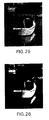
- This invention is directed to converting halftone images, such as those shown in Figs. 1 and 2, into continuous tone, or "contone", images, such as those shown in Figs. 23 and 24.
- Fig. 1 shows a 400x400 pixel error diffused halftone image.
- Fig. 2 shows the same image formed by 3x3 clustered dot halftoning.
- these images could have been formed by a halftone image generator 200, such as a computer programmed to generate halftone images for printing on a binary printer or the like.
- a halftone image generator 200 such as a computer programmed to generate halftone images for printing on a binary printer or the like.
- Such images which are formed and stored as electronic data, where the electronic data will be directly input to the universal halftone image on the screening apparatus 100, will be referred to as electronic halftone images.
- the halftone image generator 200 can be any halftone image source.
- a halftone image can be printed on a binary printer and later scanned by a scanner 300 to generate the input data for the universal halftone image unscreening apparatus 100.
- the original image resolution was 400x400 pixels.
- the original image was scaled by a factor of 2 and halftoned using 4x8 cluster dots.
- the halftone image was printed at 300 spi and was then scanned at 200 spi.
- the halftone image to be processed is an original electronic halftone image or is a scanned halftone image
- the image is input from either the halftone image generator 200 or the scanner 300 over an input line 103 to a halftone image input system 130 of the universal halftone image unscreening apparatus 100.
- the universal halftone image unscreening apparatus 100 includes a controller 110, a memory 120, the halftone image input system 130, and N-stage halftone image decomposer 140, a subband noise and/or pattern filter system 150, a N-stage subband to continuous tone image recomposer 160, a continuous tone image filter system 170 and a continuous tone image output system 180. Each of these elements is interconnected by a control bus 190 and a data bus 195.
- the universal halftone image unscreening apparatus 100 is preferably implemented on a programmed general purpose computer.
- the universal halftone image unscreening apparatus 100 can also be implemented on a special purpose computer, a programmed microprocessor or microcontroller and peripheral integrated circuit elements, and ASIC or other integrated circuit, a hardwired electronic or logic circuit such as a discrete circuit element, a programmable logic device such as a PLD, PLA or PAL, or the like.
- any device which is capable of implementing the flowcharts shown in Figs. 11-16 can be used to implement the universal halftone image unscreening apparatus 100.
- the halftone image input system 130 can be a LAN connection to a network, a modem connected by the public switch telephone network to a mainframe computer, a minicomputer, or a personal computer, a parallel or serial port connected to the scanner 300, or the like. After the halftone image data is input to the universal halftone image unscreening apparatus 100 through the halftone image input system 130, the halftone image data is stored to the memory 120.
- the memory 120 can include both writable memory, such as RAM, flash memory, PROM, EPROM and EEPROM, and nonwritable memory, such as ROM.
- writable memory such as RAM
- flash memory PROM
- EPROM EPROM
- EEPROM nonwritable memory
- ROM nonwritable memory
- the RAM is static or dynamic RAM.
- the memory 120 can also be implemented using a floppy disk and disk drive, a writable optical disk and disk drive, a hard drive, or the like.
- the original halftone image is stored in the memory 120, it is output to the N-stage halftone image decomposer 140 where it is decomposed into a plurality of subband image levels, where each subband image level comprises a plurality of subband images.
- the subband images are stored in the memory 120.
- the subband images are then output to the subband noise and/or pattern filter system 150 to filter the halftone energy out of the subband images.
- the filtered subband images are then stored to the memory 120.
- the stored filtered subband images are then output to the N-stage subband to continuous tone image recomposer 160, which recomposes the subband images back into an initial single, now contone, image.
- This initial contone image is then stored to the memory 120.
- the initial contone image is then read from the memory 120 and output to a continuous tone image filter system 170.
- the continuous tone image filter 170 filters the original contone image to form an enhanced contone image.
- the initial contone image is enhanced preferably using a nonlinear filter with spatial smoothness constraints or other edge-preserving filtering methods to smooth the initial contone image and remove any filtering or recomposition artifacts.
- the final contone image is then stored to the memory 120.
- the final contone image When the final contone image is to be printed, it is output from the memory 120 to the continuous tone image output system 180.
- the continuous tone image output system 180 outputs the final contone image to a printer 400, the halftone image generator 200 or some other device, such as a computer, a data storage device or the like, over an output line 106.
- the final contone image can be further processed.
- This further processing can include compression, image recognition, rescreening using a different halftone process or different halftoning parameters, and various image manipulation processes.
- image manipulation processes can include enlarging, reducing, flipping, rotating, and the like. While such image manipulation processes can be applied to the original halftone image, they can generally be more easily or generally applied to the descreened contone image. For example, a wider range of rotation angles can be used with the contone image.
- the continuous tone image output system 180 can be a parallel or serial printer port, a LAN connection, a modem or the like.
- the device receiving the contone image can be any device capable of performing any of the functions outline above.
- the continuous tone image output system 180 and the halftone image input system 130 will in fact be the same device and the input and output lines 103 and 106 will in fact be the same line. It should also be appreciated that it is not strictly necessary to store the processed image output from each of the halftone image input system 130, the N-stage halftone image decomposer 140, the subband noise and/or pattern filter system 150, the N-stage subband into continuous tone image recomposer 160 or the continuous tone image filter system 170. Rather, the subband images or contone image output from each of these subsystems can be input directly to the next downstream subsystem.
- FIG. 3 shows each of the subsystems as separate entities, in the programmed general purpose computer, the special purpose computer, the microprocessor, the microcontroller, the ASIC or the other devices that can be used to implement the universal halftone image unscreening apparatus 100 of this invention, the actual circuit elements implementing these subsystems are likely to be common to a plurality of, if not all of, the subsystems 110 and 130-180 of the universal halftone image unscreening apparatus 100.
- the halftone image is decomposed into different frequency subband images using the discrete wavelet transform.
- the discrete wavelet transform and its inverse transform are fully described in Wavelets and Subband Coding by M. Vetterli and J. Kovacevic, Prentice Hall PTR (1995); Wavelets and Filter Banks by G. Strang and T. Nguyen, Wellesley-Cambridge Press (1996); and Wavelet Basics by Y.T. Chan, Kluwer Academic Publishers (1995), each incorporated herein by reference.
- the discrete wavelet transform is used because the unscreening process can be done more efficiently in the resulting subband images. While the energy of the halftoning process resides primarily in the high frequency subband images, the subband images with low frequency and at coarse resolutions primarily contain the signal energy.
- Wavelet decomposition facilitates processing in both the frequency domain and the space domain.
- the signal energy and the halftoning energy are heavily mixed together.
- the high frequency subband images also contain signal energy corresponding to important edge information at edge locations.
- the image is decomposed into quadtree structured subband images.
- Each of the quadtree structured subband images has a different orientation.
- the subband images also include a low-pass frequency subband image, which is denoted as the "LL" subband image.
- a parent-descendent (or parent-child) relationship exists between the subband images at different resolution levels. This relationship is referred to as a "tree". This relationship is shown in Fig. 10. Each given coefficient of a subband image has four children at the same spatial location in the subband image of the same orientation at the next finer resolution. The exception is the low-pass LL subband image, where each coefficient has only three children. The parent-child relationship thus exists throughout the levels. In general, the magnitudes of the descendent coefficients are non-increasing relative to their parents. In other words, the power spectrum of the image decays as the frequency increases. Thus, if a coefficient is found to be insignificant in its magnitude, there is a high probability that its children will be insignificant as well.
- each high frequency subband image contains information primarily along its orientation, this can be used to further filter the remaining halftone noise from the image data.
- a one-dimensional low-pass filter is applied along the orientation of the vertically and horizontally oriented subband images.
- An X-shaped low-pass filter is applied to the diagonally oriented subband images. That is, the diagonal subband images are more heavily low-pass filtered, because they, in general, contain less signal information and more halftone noise.
- This second level of filtering is applied to all of the high frequency subband images, including those at the same coarsest resolution level as the low-pass LL subband image.
- the oriented filtering is, for example, L-point running averaging.
- the initial recomposed contone image after the two subband image filtering stages will suffer from some fuzziness or blotchiness due to signal information loss.
- high frequency signal information loss results in "ringing" artifacts.
- the recomposed continuous tone image is preferably enhanced using a nonlinear filtering with the spatial smoothness constraints modeled by a Markov random field.
- the Markov random field is incorporated using a specific Gibbs potential function called the Huber minimax function. This function is shown in Fig. 18.
- the quadratic segment of this function facilitates the smoothing of discontinuities below the threshold T, while the linear segment preserves sharp edges.
- Such image enhancement techniques significantly reduce the artifacts while preserving the original image details.
- edge-preserving filtering methods such as s-filter based filtering can also be used.
- s-filter based filtering is described in "Digital Image Smoothing and the s-Filter" by J. Lee, Computer Image Graphics and Image Processing, Vol. 24, pp. 255-269, 1983, herein incorporated by reference. In practice, the best results are obtained by sequentially processing the recomposed contone image with HMRF-based filtering and s-filter based filtering.
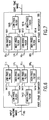
- the N-stage halftone image decomposer 140 comprises a first stage (halftone to subband) decomposer 141, a second stage (subband to subband) decomposer 142 and so on to an Nth stage (subband to subband) decomposer.
- the input halftone image is input to the N-stage halftone image decomposer 140 over the data bus 195 to the first stage decomposer 141.
- the first stage decomposer 141 generates a low-pass LL 1 subband image and three high frequency LH 1 , HL 1 and HH 1 subband images, which are output as the decomposed subband images onto the data bus 195.
- the low frequency LL 1 subband image is input to the second stage decomposer 142.
- the second stage decomposer decomposes the low frequency LL 1 subband image into a low frequency LL 2 subband image and three high frequency LH 2 , HL 2 and HH 2 subband images. These high frequency subband images are also output on the data bus 195.
- This decomposition process continues, with each successive decomposer stage decomposing the LL subband image from the previous decomposer stage, until the Nth stage decomposer 14N.
- the low frequency LL N subband image rather than being further decomposed, is output by the Nth stage decomposer 14N to the data bus 195 along with the three high frequency LH N , HL N and HH N subband images.
- the N-stage subband into continuous tone image recomposer 160 includes a first stage (subband to subband) recomposer 161, a second stage (subband to subband) recomposer 162 and so on to an Nth stage (subband to continuous tone image) recomposer 16N.
- the subband images are input to the N-stage subband to continuous tone image recomposer 160 over the data bus 195.
- the high and low frequency LL N , LH N , HL N and HH N subband images are input to the first stage recomposer 161.
- the first stage recomposer 161 outputs a recomposed low frequency LL (N-1) subband image to the second stage recomposer 162.
- the second stage recomposer 162 also inputs the high frequency LH (N-1) , HL (N-1) and HH (N-1) subband images.
- the second stage recomposer 162 recomposes these high and low frequency subband images and outputs a recomposed low frequency LL N-2 subband image.
- This recomposition process continues in successive recomposer stages until the Nth stage recomposer 16N.
- the Nth stage recomposer 16N inputs the recomposed low frequency LL N subband image from the (N-1)th stage (subband to subband) recomposer (not shown) and the high frequency LH 1 , HL 1 and HH 1 subband images from the data bus 195 and outputs the initial continuous tone image.
- the N-stage subband to continuous tone image recomposer 160 then outputs the initial contone image to the data bus 195.
- Fig. 6 shows in greater detail the structure of the first stage decomposer 141.
- the input halftone image input on the data bus 195 is input to each of a low-pass filter 1411 and a high-pass filter 1412.
- the output of the low-pass filter 1411 is input to each of a low-pass filter 1413 and a high-pass filter 1414.
- the output of the high-pass filter 1412 is input to each of a low-pass filter 1415 and a high-pass filter 1416.
- the output of the low-pass filter 1413 is the low-pass LL 1 subband image
- the output of the high-pass filter 1414 is the high frequency LH 1 subband image.
- the output of the low-pass filter 1415 is the high frequency HL 1 subband image
- the output of the high-pass filter 1416 is the high frequency HH 1 subband image. It should be appreciated that the same structure for the first stage decomposer 141 is used in each of the second-Nth stage decomposers 142-14N.
- Fig. 7 shows the preferred structure for the Nth-stage recomposer 16N.
- the low frequency LL 1 subband image is input to a low-pass filter 1611.
- the high frequency LH 1 subband image is input to a high-pass filter 1612.
- the output of the low-pass filter 1611 and the high-pass filter 1612 are combined and output to a low-pass filter 1615.
- the high frequency HL 1 subband image is input to a low-pass filter 1613, while the high frequency HH 1 subband image is input to a high-pass filter 1614.
- the output of the low-pass filter 1613 and the high-pass filter 1614 are combined and input to a high-pass filter 1616.
- each of the first-(N-1)th stages of the N-stage subband into continuous tone image recomposer 160 preferably have the same structure. In each of those stages, the output from the low-pass filter 1615 and the high-pass filter 1616, rather being the continuous tone image, is the low frequency LL subband image.
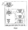
- Fig. 8 shows the preferred structure for the subband noise and/or pattern filter system 150 in greater detail.
- the subband images generated by the N-stage halftone image decomposer 140 are input over the data bus 195 to a non-edge area noise attenuation system 151.
- this non-edge area noise attenuation system 151 is preferably a tree clipper.
- the output of the non-edge area noise attenuation system 151 is output to an oriented filter system 152.
- the oriented filter system 152 preferably includes a subband orientation analyzer 153 which inputs the output from the non-edge area noise attenuation system 151 and determines the orientation for each of the subband images generated by the N-stage halftone image decomposer 140.
- the horizontal subband images are output to the horizontal subband filter 154, while the vertical subband images are output to the vertical subband filter 155 and the diagonal subband images are output to the diagonal subband filter 156.
- the horizontal subband filter 154 preferably applies a vertical low-pass filter to the horizontal subband images, while the vertical subband filter 155 preferably applies a horizontal low-pass filter to the vertical subband images.
- An X-shaped low-pass filter is preferably applied by the diagonal subband filter 156 to the diagonal subband images.
- the outputs of the horizontal, vertical and diagonal subband filters 154-156 is output by the subband noise and/or pattern filter 150 on the data bus 195 to either the memory 120 or the N-stage subband to continuous tone image recomposer 160.
- Fig. 9 graphically shows the general relationship between the original image "O" and each of the subband images "S".
- the original image O is decomposed into up to m first level subband images S(1,0) to S(1,M).
- the 0th subband image of each level i.e. the S(n,0) subband image is decomposed into up to m second level subband images S(2,0) to S(2,M). This continues until the nth level, comprising the subband images S(N,0) to S(N,M), is formed.
- the continuous tone image is created by reversing this process.
- the wavelet based unscreening apparatus and method of this invention generates four subband images in each level, the method outlined in Fig. 9 is not so limited. This is because the universal halftone image unscreening apparatus and method of this invention are not limited to the discrete wavelet transform. Rather, cosine transforms (including the discrete cosine transform), lapped transforms, Fourier transforms, and wavelet transforms without subsampling, among others, can be used in the universal halftone image unscreening apparatus and method of this invention.
- step S100 the control system implementing the flowcharts of Figs. 11-15 inputs the halftone image in step S110. Then, in step S120 the halftone image is decomposed into subband images. Next, in step S130, noise and/or patterns are selectively removed from the subband images. Then, in step S140, the subband images are recomposed into an initial continuous tone image.
- step S150 the control system determines if post filtering of the initial continuous tone image is necessary, desirable or requested. If post filtering is to be performed, control continues to step S160, where the initial continuous tone image is filtered to produce the final continuous tone image. Control then continues to step S170. If, in step S150, post filtering is not to be performed, control jumps directly to step S170. In step S170, the process stops.
- Fig. 12 shows the halftone image inputting step S110 in greater detail.
- the control system determines if the halftone image is to be scanned and input from a scanner. If it is, control continues to step S114, where the halftone image is scanned and input. Otherwise, control continues to step S116, where the halftone is input as electronic halftone image from a network or host computer, over a modem, from memory or the like. From either step S114 or step S116, control continues to step S118, which returns control to step S120.
- Fig. 13 shows the halftone image decomposing step of S120 in greater detail.
- Fig. 13 shows the preferred method of step S120 when the discrete wavelet transform is used to decompose the original halftone image. It should be appreciated that the steps shown in Fig. 13 for step S120 will be highly dependent upon the particular method used to decompose the halftone image.
- step S124 the low frequency LLN subband image is input from memory and the value of N is incremented by 1.
- step S125 the input low frequency subband image, which is now the low frequency LL (N-1) subband image, is decomposed into the next level LL N , LH N , HL N , and HH N subband images.
- These subband images are then stored to memory in step S126 and control returns to step S123.
- the control system continues to loop through steps S123-S126 until all of the subband image levels have been formed. Control then continues to step S127.
- step S127 the stored first-Nth level subband images are output for selective noise and/or pattern removal. Control then continues to step S128, which returns control to step S130.
- the subband images need not be stored to memory. In this case, rather than storing the subband images to memory in steps S122 and S126, the low frequency LL N subband images formed in step S121 and S125 are directly input to step S124 if additional subband images are to be formed in step S123.
- Fig. 14 shows in greater detail the selective noise and/or pattern removing step S130.
- step S132 the noise in non-edge areas of the subband images is attenuated.
- step S134 the subband images are filtered using oriented filters.
- step S136 control is returned to step S140.
- Fig. 15 shows the continuous tone image recomposing step S140 in greater detail.
- step S141 the Nth level LL N , LH N , HL N and HH N subband images are input from memory.
- step S142 the Nth level subband images are recomposed to form a new (N-1)th level low frequency LL (N-1) subband image.
- step S143 the value of N, which was incremented in step S124, is decremented by 1. Control then continues to step S144.
- step S144 the control system determines if N is equal to 0. If not, control continues to step S145, where, based on the new value for N, the Nth level high frequency LH N , HL N and HH N subband images are input and associated with the recomposed low frequency LL N subband image. Control then returns to step S142, where the subband images are again recomposed to form the next higher level low frequency LL subband image.
- step S146 the "LL O " image, i.e. the recomposed contone image, is output to memory.
- step S147 control returns to step S150.
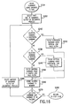
- Fig. 16 shows one preferred embodiment for the subband image filtering using oriented filters step S134.
- step S200 a first one of the subband images output or generated by the decompose process is selected. Then, in step S210, the control system determines if the selected subband image is a horizontal subband image. If not, control continues to step S230. Otherwise, control continues to step S220. In step S220, the horizontal subband image is filtered using a vertical low-pass filter. Control then continues to step S260. In step S230, the control system determines if the selected subband image is a vertical subband image. If so, control continues to step S240, where the vertical subband image is filtered using a horizontal low-pass filter.
- step S260 Control then continues to step S260. Otherwise, if, in step S230, the selected subband image is not a vertical subband image, it is a diagonal subband image. Thus, control continues to step S250, where the diagonal subband image is filtered using an X-shaped low-pass filter. Control then continues to step S260.
- step S260 the filtered subband image is stored to memory. Then, control continues to step S270.
- step S270 the control system determines if the selected subband image is the last subband image to be filtered. That is, the control system determines if all of the subband images have been filtered. If less than all of the subband images have been filtered, control continues to step S280 where another of the subband images is selected. Control then returns to step S210. Otherwise, if all the subband images have been filtered, control continues to step S290, which returns control to step S136.
- Fig. 17 shows the relationship of each of the subband images to their parent images and the parent-child relationship for the parent coefficients and the child coefficients.
- Fig. 19 shows the resulting subband images when the halftone image decomposition step S120 of Figs. 11 and 13 is applied to the clustered-dots halftone image of Fig. 2.
- Fig. 20 shows the subband images after the non-edge area noise attenuation step S132 has been applied to the subband images shown in Fig. 19.
- step S132 is implemented by tree clipping.
- Fig. 21 shows the subband images after the subband filtering using oriented filters step S134 shown in Figs. 14 and 16 has been applied to the noise attenuated subband images shown in Fig. 20.
- Fig. 22 shows the initial recomposed contone image recomposed from the filtered subband images shown in Fig. 21 based on the subband into continuous tone image recomposition step S140 shown in Figs. 11 and 15.
- Fig. 23 shows the final contone image formed by applying the continuous tone image filtering step S160 of Fig. 11 to the initial contone image shown in Fig. 22.
- Fig. 24 shows the similar final contone image resulting from applying the process outlined in Fig. 11 to the error diffused halftone image shown in Fig. 1.
- Fig. 25 shows the same image as that shown in Figs. 1 and 2 after having been printed and scanned. That is, the images shown in Figs. 1 and 2 were input to the universal unscreening apparatus and method of this invention as electronic images directly generated from a halftone image generator. In contrast, the image shown in Fig. 25 was input to the universal unscreening apparatus and method of this invention by scanning a printed halftone image.
- Fig. 26 shows the resulting contone image generated by applying the steps of Fig. 11 to the scanned halftone image shown in Fig. 25.
- the method outlined in Fig. 11 is able to generate a high quality contone image independently of the halftoning method used and independently of the image being either an electronic halftone image or a scanned halftone image.
- oriented filtering outlined above can be performed by convolution with the following types of masks for vertical, horizontal, and diagonal oriented filtering, respectively: Vertical Horizontal Diagonal 010 000 101 010 111 010 010 000 101.
Abstract
Description
| Vertical | Horizontal | Diagonal |
| 010 | 000 | 101 |
| 010 | 111 | 010 |
| 010 | 000 | 101. |
Claims (10)
- A method for creating a continuous tone image(Figs. 23 and 24) from a halftone image (Figs. 1 and 2), comprising:decomposing (S110) the halftone image into a plurality of subband images;selectively removing (S130) at least one of noise and patterns from the plurality of subband images; andrecomposing the plurality of subband images into the continuous tone image.
- A method for creating the continuous tone image from the halftone image as claimed in claim 1, further comprising filtering (S160) the continuous tone image using a non-linear, edge-preserving filter to form an enhanced continuous tone image.
- A method for creating the continuous tone image from the halftone image as claimed in claim 2, wherein the continuous tone image filtering step comprises non-linearly filtering the continuous tone image using spatial smoothness constraints modeled using a Huber Markov random field; or comprises non-linearly filtering the continuous tone image using an edge-preserving filter.
- A method for creating the continuous tone image from the halftone image as claimed in any of claims 1 to 3, wherein the halftone decomposing step comprises decomposing the halftone image into a plurality of different frequency subband images based on a discrete wavelet transform; or comprises:decomposing the halftone image into a plurality of different first level frequency subband images;decomposing one of the plurality of first level subband images into a plurality of second level different frequency subband images; andrepeating the subband image decomposing step for at least the plurality of second level subband images.
- A method for creating the continuous tone image from the halftone image as claimed in any of claims 1 to 4, wherein the selectively removing step comprises:attenuating noise from non-edge areas of each of the plurality of subband images; andoriented filtering of each of the plurality of noise-attenuated subband images.
- A method for creating the continuous tone image from the halftone image as claimed in claim 5, wherein the noise-attenuating step comprises clipping the magnitudes of the pixels of high frequency subband images; or wherein the noise-attenuating step comprises:weighting magnitudes of coefficients for a parent subband image for each high frequency subband image; andclipping magnitudes of coefficients of the high frequency subband images to at most the weighted magnitudes of the coefficients of the corresponding parent subband image.
- A method for creating the continuous tone image from the halftone image as claimed in claim 5 or 6, wherein the oriented filtering step comprises applying a one-dimensional low-pass filter along an orientation of each subband image; or wherein oriented filtering step comprises applying one of a plurality of oriented filters to each of the subband images, the plurality of oriented filters comprising a horizontal low-pass filter, a vertical low-pass filter and a X-shaped low-pass filter; or wherein the oriented filtering step comprises:applying a horizontal low-pass filter to vertical subband images;applying a vertical low-pass filter to horizontal subband images; andapplying a X-shaped low-pass filter to diagonal subband images; or wherein the oriented filtering step comprises adapting the oriented filtering to a resolution of the subband images; or wherein the oriented filtering step further comprises selecting appropriate filters based on estimates of the screen parameters.
- An apparatus for converting a halftone image (Figs. 1,2) into a continuous tone image (Figs. 2, 3, 24), comprising:decomposing means (140) for decomposing the halftone image into a plurality of subband images;means for selectively removing at least one of noise and patterns from the plurality of subband images; andrecomposing means (160) for recomposing the plurality of subband images into the continuous tone image.
- An apparatus for converting a halftone image into a continuous tone image, comprising:an N-stage halftone image decomposer;a subband noise/pattern filter system; andan N-stage subband image recomposer.
- An apparatus for converting a halftone image into a continuous tone image as claimed in claim 9, wherein the N-stage halftone image decomposer comprises:a halftone image to subband image decomposer; andat least one subband image to subband image decomposer; and/or wherein the N-stage subband image recomposer comprises:at least one subband image to subband image recomposer; anda subband image to continuous tone image recomposer; and/or wherein the subband noise/pattern filter system comprises:a non-edge area noise attenuating filter; anda subband image oriented filter system.
Applications Claiming Priority (2)
| Application Number | Priority Date | Filing Date | Title |
|---|---|---|---|
| US708014 | 1996-08-30 | ||
| US08/708,014 US5799112A (en) | 1996-08-30 | 1996-08-30 | Method and apparatus for wavelet-based universal halftone image unscreening |
Publications (3)
| Publication Number | Publication Date |
|---|---|
| EP0827333A2 true EP0827333A2 (en) | 1998-03-04 |
| EP0827333A3 EP0827333A3 (en) | 1999-12-29 |
| EP0827333B1 EP0827333B1 (en) | 2008-08-13 |
Family
ID=24844043
Family Applications (1)
| Application Number | Title | Priority Date | Filing Date |
|---|---|---|---|
| EP97306400A Expired - Lifetime EP0827333B1 (en) | 1996-08-30 | 1997-08-21 | Method and apparatus for creating a continuous tone image from a halftone image |
Country Status (4)
| Country | Link |
|---|---|
| US (1) | US5799112A (en) |
| EP (1) | EP0827333B1 (en) |
| JP (1) | JP3964503B2 (en) |
| DE (1) | DE69738897D1 (en) |
Cited By (7)
| Publication number | Priority date | Publication date | Assignee | Title |
|---|---|---|---|---|
| EP0946047A2 (en) * | 1998-01-30 | 1999-09-29 | Digital Equipment Corporation | Method for low complexity, low memory inverse dithering |
| EP1168824A2 (en) * | 2000-06-29 | 2002-01-02 | Eastman Kodak Company | Image processing method for reducing noise and blocking artifact in a digital image |
| EP1215883A2 (en) * | 2000-12-06 | 2002-06-19 | Xerox Corporation | Adaptive filtering method and apparatus for descreening scanned halftoned image representations |
| EP1341123A1 (en) * | 2000-11-30 | 2003-09-03 | Canon Kabushiki Kaisha | Image processing device, image processing method, storage medium, and program |
| EP1850291A2 (en) * | 2006-04-28 | 2007-10-31 | Xerox Corporation | System and method for enhancing stored binary images |
| US7447376B2 (en) | 2000-11-30 | 2008-11-04 | Canon Kabushiki Kaisha | Image processing apparatus, image processing method, storage medium, and program |
| CN110677140A (en) * | 2019-10-28 | 2020-01-10 | 北京航空航天大学 | Random system filter containing unknown input and non-Gaussian measurement noise |
Families Citing this family (49)
| Publication number | Priority date | Publication date | Assignee | Title |
|---|---|---|---|---|
| US6108098A (en) * | 1995-12-28 | 2000-08-22 | Canon Kabushiki Kaisha | Image processing apparatus and method |
| JPH09214807A (en) * | 1996-01-31 | 1997-08-15 | Canon Inc | Device and method for processing image |
| US6233060B1 (en) * | 1998-09-23 | 2001-05-15 | Seiko Epson Corporation | Reduction of moiré in screened images using hierarchical edge detection and adaptive-length averaging filters |
| US6768518B1 (en) * | 1998-12-16 | 2004-07-27 | Xerox Corporation | Method and apparatus for removing a checkerboard-like noise artifact from a captured composite NTSC video frame |
| US6580837B1 (en) * | 1999-12-07 | 2003-06-17 | Intel Corporation | Up-sampling decimated color plane data |
| US6973127B1 (en) * | 1999-12-23 | 2005-12-06 | Xvd Corporation | Apparatus and method for memory saving wavelet based video coding |
| US6864994B1 (en) * | 2000-01-19 | 2005-03-08 | Xerox Corporation | High-speed, high-quality descreening system and method |
| US6721458B1 (en) | 2000-04-14 | 2004-04-13 | Seiko Epson Corporation | Artifact reduction using adaptive nonlinear filters |
| US7107453B2 (en) * | 2000-05-25 | 2006-09-12 | Hewlett-Packard Development Company, L.P. | Authenticatable graphical bar codes |
| US6751352B1 (en) | 2000-05-25 | 2004-06-15 | Hewlett-Packard Development Company, L.P. | Method and apparatus for generating and decoding a visually significant barcode |
| US7187475B1 (en) * | 2000-09-28 | 2007-03-06 | Zoran Corporation | System and method for a robust de-screening filter |
| US6731821B1 (en) * | 2000-09-29 | 2004-05-04 | Hewlett-Packard Development Company, L.P. | Method for enhancing compressibility and visual quality of scanned document images |
| US6938017B2 (en) * | 2000-12-01 | 2005-08-30 | Hewlett-Packard Development Company, L.P. | Scalable, fraud resistant graphical payment indicia |
| US6738524B2 (en) | 2000-12-15 | 2004-05-18 | Xerox Corporation | Halftone detection in the wavelet domain |
| US7006255B2 (en) * | 2001-03-29 | 2006-02-28 | Sharp Laboratories Of America | Adaptive image filtering based on a distance transform |
| US6839450B2 (en) * | 2001-04-26 | 2005-01-04 | Hewlett-Packard Development Company, L.P. | Detecting halftone modulations embedded in an image |
| US7028060B2 (en) * | 2001-05-07 | 2006-04-11 | Hrl Laboratories Llc | Method and apparatus for jointly optimizing linear signal processing filters with subband filters |
| US7206459B2 (en) * | 2001-07-31 | 2007-04-17 | Ricoh Co., Ltd. | Enhancement of compressed images |
| US7187806B2 (en) * | 2001-08-23 | 2007-03-06 | Hewlett-Packard Development Company, L.P. | System and method for embedding information within a printed image using block error diffusion halftoning |
| KR100403601B1 (en) * | 2001-12-21 | 2003-10-30 | 삼성전자주식회사 | Apparatus and method for enhancing edge of image |
| US7085015B2 (en) | 2002-02-01 | 2006-08-01 | Seiko Epson Corporation | Inverse halftoning for multi-level halftones |
| US7120305B2 (en) * | 2002-04-16 | 2006-10-10 | Ricoh, Co., Ltd. | Adaptive nonlinear image enlargement using wavelet transform coefficients |
| US7185388B2 (en) * | 2002-08-06 | 2007-03-06 | Harper Brush Works, Inc. | Power wave floor squeegee and handle connector |
| US6993185B2 (en) | 2002-08-30 | 2006-01-31 | Matsushita Electric Industrial Co., Ltd. | Method of texture-based color document segmentation |
| US7430334B2 (en) * | 2003-07-31 | 2008-09-30 | Hewlett Packard Development Company, L.P. | Digital imaging systems, articles of manufacture, and digital image processing methods |
| WO2005046213A1 (en) * | 2003-11-06 | 2005-05-19 | National University Of Singapore | Document image encoding/decoding |
| US7653255B2 (en) | 2004-06-02 | 2010-01-26 | Adobe Systems Incorporated | Image region of interest encoding |
| US8059910B2 (en) * | 2005-03-31 | 2011-11-15 | Nikon Corporation | Image processing method for removing noise from an image |
| US7561747B2 (en) * | 2005-12-23 | 2009-07-14 | Xerox Corporation | Image data processing system and method |
| JP4847531B2 (en) * | 2006-08-17 | 2011-12-28 | 富士通株式会社 | Image processing apparatus, image processing program, and image processing method |
| WO2009081485A1 (en) * | 2007-12-25 | 2009-07-02 | Fujitsu Limited | Image processing apparatus, image processing method and image processing program |
| JP5213670B2 (en) * | 2008-01-16 | 2013-06-19 | 三洋電機株式会社 | Imaging apparatus and blur correction method |
| US8120679B2 (en) * | 2008-08-01 | 2012-02-21 | Nikon Corporation | Image processing method |
| US8077357B2 (en) * | 2008-09-30 | 2011-12-13 | Xerox Corporation | Content-aware resizing of uniform rosette color halftone images |
| US8077356B2 (en) * | 2008-09-30 | 2011-12-13 | Xerox Corporation | Content-aware halftone image resizing using iterative determination of energy metrics |
| US8098404B2 (en) * | 2008-09-30 | 2012-01-17 | Xerox Corporation | Content-aware uniform rosette color halftone image resizing using iterative determination of energy metrics |
| US8023153B2 (en) * | 2008-09-30 | 2011-09-20 | Xerox Corporation | Content-aware halftone image resizing |
| US8515182B2 (en) * | 2009-02-11 | 2013-08-20 | Ecole De Technologie Superieure | Method and system for determining a quality measure for an image using multi-level decomposition of images |
| US8326046B2 (en) | 2009-02-11 | 2012-12-04 | Ecole De Technologie Superieure | Method and system for determining structural similarity between images |
| US8515181B2 (en) | 2009-02-11 | 2013-08-20 | Ecole De Technologie Superieure | Method and system for determining a quality measure for an image using a variable number of multi-level decompositions |
| US8760572B2 (en) * | 2009-11-19 | 2014-06-24 | Siemens Aktiengesellschaft | Method for exploiting structure in sparse domain for magnetic resonance image reconstruction |
| US8983206B2 (en) | 2011-05-04 | 2015-03-17 | Ecole de Techbologie Superieure | Method and system for increasing robustness of visual quality metrics using spatial shifting |
| JP5773781B2 (en) * | 2011-06-30 | 2015-09-02 | 株式会社東芝 | Ultrasonic diagnostic apparatus, image processing apparatus, and program |
| CN104137144B (en) * | 2012-02-29 | 2017-03-08 | 独立行政法人科学技术振兴机构 | Image procossing digital filter and character string inclination illusion generating means |
| TWI532011B (en) * | 2012-05-14 | 2016-05-01 | 國立研究開發法人科學技術振興機構 | Image processing device, image processing method, program, print medium and recording medium |
| KR20150100929A (en) * | 2013-01-30 | 2015-09-02 | 고쿠리츠켄큐카이하츠호진 카가쿠기쥬츠신코키코 | Image processing digital filter, image processing device, printing medium, recording medium, image processing method and program |
| US9215345B2 (en) * | 2013-03-26 | 2015-12-15 | Xerox Corporation | Method and system for inverse halftoning utilizing inverse projection of predicted errors |
| CN108734680A (en) * | 2018-05-29 | 2018-11-02 | 电子科技大学 | A kind of image repair method of adaptively selected sample block size |
| CN108876741B (en) * | 2018-06-22 | 2021-08-24 | 中国矿业大学(北京) | Image enhancement method under complex illumination condition |
Citations (4)
| Publication number | Priority date | Publication date | Assignee | Title |
|---|---|---|---|---|
| US5239390A (en) * | 1992-06-05 | 1993-08-24 | Eastman Kodak Company | Image processing method to remove halftone screens |
| US5243444A (en) * | 1992-03-25 | 1993-09-07 | Xerox Corporation | Image processing system and method with improved reconstruction of continuous tone images from halftone images including those without a screen structure |
| EP0611051A1 (en) * | 1993-01-22 | 1994-08-17 | Canon Kabushiki Kaisha | Image processing method and apparatus |
| EP0682320A2 (en) * | 1994-05-11 | 1995-11-15 | Xerox Corporation | Stack filters for 1-to-N bit image processing in electronic printers |
Family Cites Families (4)
| Publication number | Priority date | Publication date | Assignee | Title |
|---|---|---|---|---|
| US4630125A (en) * | 1983-06-01 | 1986-12-16 | Xerox Corporation | Unscreening of stored digital halftone images |
| US5027078A (en) * | 1989-10-10 | 1991-06-25 | Xerox Corporation | Unscreening of stored digital halftone images by logic filtering |
| US5339170A (en) * | 1991-12-31 | 1994-08-16 | Xerox Corporation | Image processing system and method employing hybrid filtering to provide improved reconstruction of continuous tone images from halftone screen-structured images |
| US5343309A (en) * | 1992-08-12 | 1994-08-30 | Xerox Corporation | Image processing system and method employing adaptive filtering to provide improved reconstruction of continuous tone images from halftone images including those without a screen structure |
-
1996
- 1996-08-30 US US08/708,014 patent/US5799112A/en not_active Expired - Lifetime
-
1997
- 1997-08-21 EP EP97306400A patent/EP0827333B1/en not_active Expired - Lifetime
- 1997-08-21 DE DE69738897T patent/DE69738897D1/en not_active Expired - Lifetime
- 1997-08-22 JP JP24196397A patent/JP3964503B2/en not_active Expired - Fee Related
Patent Citations (4)
| Publication number | Priority date | Publication date | Assignee | Title |
|---|---|---|---|---|
| US5243444A (en) * | 1992-03-25 | 1993-09-07 | Xerox Corporation | Image processing system and method with improved reconstruction of continuous tone images from halftone images including those without a screen structure |
| US5239390A (en) * | 1992-06-05 | 1993-08-24 | Eastman Kodak Company | Image processing method to remove halftone screens |
| EP0611051A1 (en) * | 1993-01-22 | 1994-08-17 | Canon Kabushiki Kaisha | Image processing method and apparatus |
| EP0682320A2 (en) * | 1994-05-11 | 1995-11-15 | Xerox Corporation | Stack filters for 1-to-N bit image processing in electronic printers |
Cited By (17)
| Publication number | Priority date | Publication date | Assignee | Title |
|---|---|---|---|---|
| EP0946047A3 (en) * | 1998-01-30 | 1999-12-22 | Digital Equipment Corporation | Method for low complexity, low memory inverse dithering |
| US6163629A (en) * | 1998-01-30 | 2000-12-19 | Compaq Computer Corporation | Method for low complexity low memory inverse dithering |
| EP0946047A2 (en) * | 1998-01-30 | 1999-09-29 | Digital Equipment Corporation | Method for low complexity, low memory inverse dithering |
| EP1168824A2 (en) * | 2000-06-29 | 2002-01-02 | Eastman Kodak Company | Image processing method for reducing noise and blocking artifact in a digital image |
| EP1168824A3 (en) * | 2000-06-29 | 2004-08-25 | Eastman Kodak Company | Image processing method for reducing noise and blocking artifact in a digital image |
| US7447376B2 (en) | 2000-11-30 | 2008-11-04 | Canon Kabushiki Kaisha | Image processing apparatus, image processing method, storage medium, and program |
| EP1341123A1 (en) * | 2000-11-30 | 2003-09-03 | Canon Kabushiki Kaisha | Image processing device, image processing method, storage medium, and program |
| US7561750B2 (en) | 2000-11-30 | 2009-07-14 | Canon Kabushiki Kaisha | Image processing apparatus, image processing method, storage medium, and program |
| US7558434B2 (en) | 2000-11-30 | 2009-07-07 | Canon Kabushiki Kaisha | Image processing apparatus, image processing method, storage medium, and program |
| EP1341123A4 (en) * | 2000-11-30 | 2007-07-25 | Canon Kk | Image processing device, image processing method, storage medium, and program |
| EP1816603A1 (en) * | 2000-11-30 | 2007-08-08 | Canon Kabushiki Kaisha | Image processing device, image processing method, storage medium, and program |
| EP1215883A2 (en) * | 2000-12-06 | 2002-06-19 | Xerox Corporation | Adaptive filtering method and apparatus for descreening scanned halftoned image representations |
| US6839152B2 (en) | 2000-12-06 | 2005-01-04 | Xerox Corporation | Adaptive filtering method and apparatus for descreening scanned halftoned image representations |
| EP1215883A3 (en) * | 2000-12-06 | 2003-10-29 | Xerox Corporation | Adaptive filtering method and apparatus for descreening scanned halftoned image representations |
| EP1850291A2 (en) * | 2006-04-28 | 2007-10-31 | Xerox Corporation | System and method for enhancing stored binary images |
| EP1850291A3 (en) * | 2006-04-28 | 2010-05-19 | Xerox Corporation | System and method for enhancing stored binary images |
| CN110677140A (en) * | 2019-10-28 | 2020-01-10 | 北京航空航天大学 | Random system filter containing unknown input and non-Gaussian measurement noise |
Also Published As
| Publication number | Publication date |
|---|---|
| JPH1098628A (en) | 1998-04-14 |
| EP0827333B1 (en) | 2008-08-13 |
| EP0827333A3 (en) | 1999-12-29 |
| US5799112A (en) | 1998-08-25 |
| DE69738897D1 (en) | 2008-09-25 |
| JP3964503B2 (en) | 2007-08-22 |
Similar Documents
| Publication | Publication Date | Title |
|---|---|---|
| US5799112A (en) | Method and apparatus for wavelet-based universal halftone image unscreening | |
| US5343309A (en) | Image processing system and method employing adaptive filtering to provide improved reconstruction of continuous tone images from halftone images including those without a screen structure | |
| US6101285A (en) | Filter for producing continuous tone images from halftone digital images data | |
| EP0562813B1 (en) | System and method for converting halftone images to continuous-tone images | |
| US7599095B2 (en) | Wavelet-based image processing path | |
| JP2925325B2 (en) | Method for halftone continuous tone image for efficient transmission and reception, and facsimile apparatus implementing the method | |
| Luo et al. | A robust technique for image descreening based on the wavelet transform | |
| Stevenson | Inverse halftoning via MAP estimation | |
| US7580074B2 (en) | Digital halftoning technique based on 1-D multi-scale dot assignment | |
| US5111310A (en) | Method and apparatus for halftone rendering of a gray scale image using a blue noise mask | |
| EP1215883B1 (en) | Adaptive filtering method and apparatus for descreening scanned halftoned image representations | |
| US6864994B1 (en) | High-speed, high-quality descreening system and method | |
| US9215345B2 (en) | Method and system for inverse halftoning utilizing inverse projection of predicted errors | |
| Damera-Venkata et al. | Fast blind inverse halftoning | |
| Foi et al. | Inverse halftoning based on the anisotropic LPA-ICI deconvolution | |
| Siddiqui et al. | Training-based descreening | |
| Egiazarian et al. | Adaptive denoising and lossy compression of images in transform domain | |
| Chen et al. | An adaptive inverse halftoning algorithm | |
| Luo et al. | Universal descreening technique via wavelet analysis | |
| Lee et al. | LPI adaptive descreening method with Hadamard domain analysis | |
| Lee et al. | Region-based printing quality enhancement | |
| Nishida | Adaptive inverse halftoning for scanned document images through multiresolution and multiscale analysis | |
| Berkner | Enhancement of scanned documents in Besov spaces using wavelet domain representations | |
| Kuo et al. | Color halftone document segmentation and descreening | |
| Fan | Unscreening using a hybrid filtering approach |
Legal Events
| Date | Code | Title | Description |
|---|---|---|---|
| PUAI | Public reference made under article 153(3) epc to a published international application that has entered the european phase |
Free format text: ORIGINAL CODE: 0009012 |
|
| AK | Designated contracting states |
Kind code of ref document: A2 Designated state(s): DE FR GB |
|
| PUAL | Search report despatched |
Free format text: ORIGINAL CODE: 0009013 |
|
| AK | Designated contracting states |
Kind code of ref document: A3 Designated state(s): AT BE CH DE DK ES FI FR GB GR IE IT LI LU MC NL PT SE |
|
| 17P | Request for examination filed |
Effective date: 20000629 |
|
| AKX | Designation fees paid |
Free format text: DE FR GB |
|
| GRAP | Despatch of communication of intention to grant a patent |
Free format text: ORIGINAL CODE: EPIDOSNIGR1 |
|
| GRAS | Grant fee paid |
Free format text: ORIGINAL CODE: EPIDOSNIGR3 |
|
| GRAA | (expected) grant |
Free format text: ORIGINAL CODE: 0009210 |
|
| AK | Designated contracting states |
Kind code of ref document: B1 Designated state(s): DE FR GB |
|
| REG | Reference to a national code |
Ref country code: GB Ref legal event code: FG4D |
|
| REF | Corresponds to: |
Ref document number: 69738897 Country of ref document: DE Date of ref document: 20080925 Kind code of ref document: P |
|
| PLBE | No opposition filed within time limit |
Free format text: ORIGINAL CODE: 0009261 |
|
| STAA | Information on the status of an ep patent application or granted ep patent |
Free format text: STATUS: NO OPPOSITION FILED WITHIN TIME LIMIT |
|
| 26N | No opposition filed |
Effective date: 20090514 |
|
| PGFP | Annual fee paid to national office [announced via postgrant information from national office to epo] |
Ref country code: DE Payment date: 20130722 Year of fee payment: 17 |
|
| PGFP | Annual fee paid to national office [announced via postgrant information from national office to epo] |
Ref country code: FR Payment date: 20130820 Year of fee payment: 17 Ref country code: GB Payment date: 20130725 Year of fee payment: 17 |
|
| REG | Reference to a national code |
Ref country code: DE Ref legal event code: R119 Ref document number: 69738897 Country of ref document: DE |
|
| GBPC | Gb: european patent ceased through non-payment of renewal fee |
Effective date: 20140821 |
|
| REG | Reference to a national code |
Ref country code: DE Ref legal event code: R119 Ref document number: 69738897 Country of ref document: DE Effective date: 20150303 |
|
| REG | Reference to a national code |
Ref country code: FR Ref legal event code: ST Effective date: 20150430 |
|
| PG25 | Lapsed in a contracting state [announced via postgrant information from national office to epo] |
Ref country code: DE Free format text: LAPSE BECAUSE OF NON-PAYMENT OF DUE FEES Effective date: 20150303 Ref country code: GB Free format text: LAPSE BECAUSE OF NON-PAYMENT OF DUE FEES Effective date: 20140821 |
|
| PG25 | Lapsed in a contracting state [announced via postgrant information from national office to epo] |
Ref country code: FR Free format text: LAPSE BECAUSE OF NON-PAYMENT OF DUE FEES Effective date: 20140901 |