EP0831484A1 - Data reconstruction method and data storage system - Google Patents
Data reconstruction method and data storage system Download PDFInfo
- Publication number
- EP0831484A1 EP0831484A1 EP95921142A EP95921142A EP0831484A1 EP 0831484 A1 EP0831484 A1 EP 0831484A1 EP 95921142 A EP95921142 A EP 95921142A EP 95921142 A EP95921142 A EP 95921142A EP 0831484 A1 EP0831484 A1 EP 0831484A1
- Authority
- EP
- European Patent Office
- Prior art keywords
- data
- stored
- data storage
- reconstructed
- parity
- Prior art date
- Legal status (The legal status is an assumption and is not a legal conclusion. Google has not performed a legal analysis and makes no representation as to the accuracy of the status listed.)
- Withdrawn
Links
Images


Classifications
-
- G—PHYSICS
- G06—COMPUTING; CALCULATING OR COUNTING
- G06F—ELECTRIC DIGITAL DATA PROCESSING
- G06F11/00—Error detection; Error correction; Monitoring
- G06F11/07—Responding to the occurrence of a fault, e.g. fault tolerance
- G06F11/08—Error detection or correction by redundancy in data representation, e.g. by using checking codes
- G06F11/10—Adding special bits or symbols to the coded information, e.g. parity check, casting out 9's or 11's
- G06F11/1076—Parity data used in redundant arrays of independent storages, e.g. in RAID systems
- G06F11/1092—Rebuilding, e.g. when physically replacing a failing disk
-
- G—PHYSICS
- G06—COMPUTING; CALCULATING OR COUNTING
- G06F—ELECTRIC DIGITAL DATA PROCESSING
- G06F11/00—Error detection; Error correction; Monitoring
Landscapes
- Engineering & Computer Science (AREA)
- Theoretical Computer Science (AREA)
- Quality & Reliability (AREA)
- Physics & Mathematics (AREA)
- General Engineering & Computer Science (AREA)
- General Physics & Mathematics (AREA)
- Techniques For Improving Reliability Of Storages (AREA)
Abstract
An object of this invention is to restrict the degradation of performance in data reconstruction and to eliminate
the necessity for additional redundant data storages. If one of a plurality of data storages in a system is out of order,
the data in the defective storage are reconstructed on the basis of data in the other storages. The data reconstruction
method comprising a step of reading out data from data storages, a step of reading out parity data from a data storage
storing the parity data, a step of reconstructing data stored in the defective storage by executing a logical operation
between the data and the parity data, and a step of replacing the parity data stored in the storage by reconstructed data.
Description
The present invention is related to a method for data
reconstruction and a data storage system, and particularly to a
method and apparatus for reconstructing the data stored in a
broken data storage device which is part of a plurality of data
storage devices.
As the amount of data treated by a computer increases, the
increase of the throughput of a HDD (Hard Disk Drive) and the
increase of reliability of data storage are needed. The RAID
(Redundant Array of Inexpensive Disks) subsystem is one of the
systems which answer such need. This subsystem is one in which
a plurality of HDDs is operated apparently as one HDD when viewed
from the point of a system, thereby to achieve a large storage
capacity and increase the throughput. Further, it is also a
subsystem in which, by ensuring high reliability, namely, by
providing parity data, data stored in a HDD can be reconstructed
when the HDD fails. The data reconstruction is achieved by
calculating redundant data called parity data from data stored
in the HDD, and storing the redundant data in the HDD.
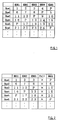
The reconstruction of data stored in a broken HDD is performed
as follows. Fig. 1 is a figure showing the construction of the
data blocks which are stored in five HDDs in a RAID5,
respectively. The RAID5 represents a system in which generated
parity data is distributively stored in the respective HDDs. In
this figure, "P" represents parity data. In addition, the
numbers (1 to 24) means the block numbers of data. A data block
means the amount of data which is collectively handled by a HDD.
This data amount is independently set for each subsystem, for
instance, to one byte to several sectors (usually, one sector is
512 bytes). By distributively storing data in four HDDs, and
storing the parity data generated from those data in the
remaining one, as described above, a lateral line of data array
("Row") is formed.
In this case, the parity data in Row 1 is generated by the
following steps.
(EX-OR means exclusive-OR.)
That is, the parity data is calculated through the three steps
of obtaining Pl by an exclusive-OR operation of data stored in
the HDD 1 and HDD 2, obtaining P2 by an exclusive-OR operation
of Pl and the data stored in the HDD 3, and then obtaining P by
the exclusive-OR of P2 and the data stored in the HDD 4. This
parity data is data necessary for reconstructing the data in any
broken HDD.
Fig. 2 is a figure showing the data construction when the HDD 4
breaks down. Since the HDD 4 is faulty, the data of a block 4
is lost in Row 1, the parity data is lost in Row 2, and the data
of a block 9 is lost in Row 3. To read the block 4 of Row 1
recorded in the broken HDD 4, the data of the block 4 is
reconstructed through the following three steps.
As described above, since there is provided redundant data named
parity data, even if any of a plurality of HDDs breaks down, the
data stored in the broken HDD can be reconstructed by carrying
out exclusive-OR operations of the data stored in the other
normal HDDs. The exclusive-OR operations are executed by a
parity generator connected to the HDDs via the data buses. The
temporary data Pl and P2 determined by the exclusive-OR
operations are temporarily stored in a parity memory connected
to the parity generator.
However, in the reconstruction of data required when there is a
broken HDD, a step of transferring the data stored in the other
HDDs to the data bus needs to be performed a plurality of times.
In the above example, three data transfers are required. The
data transfers increase as the number of the HDDs of the system
increases. Accordingly, the system performance in the data
reconstruction would largely degrade as compared with that in the
normal operation.
There is a conventional technique in which, in addition to the
HDDs that are normally used, there is provided a backup HDD to
be used for storing the reconstructed data when a HDD breaks
down. This is a technique in which, in the data reconstruction,
the data reconstructed from the data stored in the HDDs other
than the broken HDD is stored in the backup HDD. In this
technique, however, the backup HDD is not normally used, and thus
the storage capacity of the whole data storage system decreases.
This is not economical.
Thus, in the prior art, there was a problem that the speed of
reading the data stored in HDDs slowed down as compared with the
normal operation if there was a broken HDD. Moreover, there was
a problem that the storage capacity of the whole system decreased
if a backup HDD was provided.
Accordingly, in view of the above problems, it is an object of
the present invention to suppress the degradation of the
performance in the data reconstruction. Further, it is another
object of the present invention to eliminate the need for further
providing a redundant data storage device.
The present invention provides a method in which, if a broken
data storage device exists in a system having a plurality of data
storage devices, the data stored in the broken data storage
device is reconstructed based on the data stored in the other
plurality of data storage devices, the method comprising a step
of reading data from the plurality of data storage devices, a
step of reading parity data from the data storage device in which
the parity data is stored, a step of reconstructing the data
stored in the broken data storage device by carrying out logical
operations of the data and the parity data, and a step of storing
the reconstructed data by replacing the parity data stored in the
data storage device by the reconstructed data.
Also, a further invention provides a method in which, if a broken
data storage device exists in a system having a plurality of data
storage devices, the data stored in the broken data storage
device is reconstructed based on the data stored in the other
plurality of data storage devices, the method comprising a step
of reading data blocks from the plurality of data storage
devices, a step of specifying an address region to read the
parity data block stored in the address region from the data
storage device in which the parity data block is stored, a step
of obtaining a reconstructed data block by carrying out logical
operations of the data blocks and the parity data block, and a
step of storing the reconstructed data block in the address
region.
These inventions may have a further step of preparing a
management table indicating whether the parity data stored in the
data storage device has been replaced by the reconstructed data.
Specifically, this management table indicates the range of the
address region and whether or not the reconstructed data is
stored within the range.
By referencing the management table, it is determined whether or
not the reconstructed data block is stored in the address region.
If the reconstructed data is stored, it is outputted to the
outside. If the reconstructed data block is not stored, the
reconstructed data block is obtained based on the data blocks
stored in the data storage devices other than the broken data
storage device and the parity data block stored in the address
region, and it is outputted to the outside. At this point, the
reconstructed data block is stored in the address region and the
management table is updated.
Moreover, a further invention provides a data storage system
having a plurality of data storage means in which, by storing
parity data, the data stored in any of the data storage means can
be reconstructed even if that data storage means breaks down, the
system comprising a plurality of data storage means in which data
and parity data are stored, data buses connected to the data
storage means, calculation means connected to the data buses for
generating a reconstructed data based on the data and parity data
stored in the other plurality of data storage means, thereby to
reconstruct the data stored in any data storage means, and means
for writing the reconstructed data to replace the parity data
stored in the data storage means.
In addition, a further invention provides a data storage system
having a plurality of data storage means in which, by storing
parity data, the data stored in any of the data storage means can
be reconstructed even if that data storage means breaks down, the
system comprising first data storage means having a parity data
block stored in a specified address region, at least second data
storage means in which data blocks are stored, calculation means
for generating a reconstructed data block based on the parity
data block stored in the first data storage means and the data
blocks stored in the remaining second data storage means, thereby
to reconstruct the data block stored in any second data storage
means, and means for storing the reconstructed data block in the
address region.
Now, the preferred embodiment of the present invention is
described by taking a system, a so-called RAID5, as an example.
Fig. 3 is a block diagram of a RAID system in which five HDDs are
connected. To a plurality of data buses Bus 1 and Bus 2, a
plurality of data storage means 1 is connected through an
interface 2. To the data buses Bus 1 and Bus 2, one end of a
buffer 3 is connected. The other end of the buffer 3 is
connected to a cache memory 4 and a host interface 5. Further,
to the data buses Bus 1 and Bus 2, a parity generator 6 is
connected, and a parity memory 7 is connected to the parity
generator 6. The data transfer in this system is controlled by
a DMAC (Direct Memory Access Controller), not shown. In
addition, the control and management in the whole system are
performed by an MPU, not shown.
Each of the data buses Bus 1 and Bus 2 is made up of a plurality
of (for instance, 16) data lines. Further, interface 2 enables
free transfer between the data buses Bus 1, Bus 2 and the data
storage means 1. The data storage means 1 is to store data and
parity data, and it is described in this embodiment by taking a
HDD (Hard Disk Drive), a typical storage device, as an example.
However, it is to be understood that the data storage means is
not limited to HDD, but it may be a magneto-optic disk, CD-ROM,
DAT, or a semiconductor memory such as EEPROM.
The buffer 3 is to perform the data transfer between the host
interface 5 and the plurality of data buses Bus 1 and Bus 2. The
host interface 5 is to perform the data transfer between the
system and the host computer. The cache memory 4 is to
temporarily store the data transferred to the data buses Bus 1
and Bus 2 and outputted from the buffer 3, or the data
transferred from the host computer through the host interface 5.
Further, the parity generator 6 is to reconstruct the data stored
in any data storage means 1 by generating reconstructed data
based on the data and the parity data which are stored in the
other plurality of data storage means. In this embodiment,
parity data is obtained by performing an exclusive-OR operation
based on the data transferred to the data buses Bus 1 and Bus 2,
or on the data stored in the parity memory 7. Although various
calculation methods have been proposed for the generation of
parity data, the typical exclusive-OR operation is used a memory
in this embodiment. The parity memory 7 is a memory to
temporarily store the parity data calculated by the parity
generator 6.
Moreover, the parity generator 6 can fetch data from the two data
buses Bus 1 and Bus 2, generate parity data from those data, and
transfer it to the parity memory 7. It can also generate new
parity data based on the data transferred to one data bus and the
parity data read out from the parity memory 7, and store it again
in the parity memory 7 or transfer it to the other data bus.
In addition, this system has a register, not shown, as management
means. The register has a management table to be detailed later.
The MPU, not shown, performs the referencing and rewriting of the
contents of the management table. Description is now made to the
circuit operation performed when a failure occurs in the RAID5,
in which the generated parity data is distributively stored in
the individual HDD. However, the present invention is not
limited to the RAID5, but it may naturally be used in a disk
array system having a function of reconstructing data, such as
a RAID3 in which one HDD is defined as the HDD for storing parity
data and all parity data are stored in this HDD.
As shown in Fig. 2, the reconstruction when the HDD 4 breaks down
is described. Since the HDD 4 is broken, the data of a block 4
is lost in Row 1, the parity data is lost in Row 2, and the data
of a block 9 is lost in Row 3. To read the block 4 in Row 1
stored in the broken HDD 4, the data of the block 4 is
reconstructed through the following four steps.
From the HDD 1 and HDD 2, the data of the blocks 1 and 2 are read
out, respectively, and transferred to the data buses Bus 1 and
Bus 2. These transferred data blocks are inputted to the parity
generator 6. The parity generator 6 generates a parity block Pl
by calculating the exclusive-OR of the data of the blocks 1 and
2. The parity block Pl is stored in the parity memory 7.
The data of the block 3 is read from the HDD 3 and transferred
to any one data bus. The transferred data block is inputted to
the parity generator 6. The parity generator 6 generates a
parity block P2 by calculating the exclusive-OR of the block 3
and the parity block Pl stored in the parity memory 7. The
parity block P2 is stored in the parity memory 7.
By specifying an address region, the data of a parity block P
stored in this region is read out from the HDD 5, and transferred
to any one data bus. The transferred parity block P is inputted
to the parity generator 6. The parity generator 6 generates a
reconstructed data block A by calculating the exclusive-OR of the
parity block P and the parity block P2 stored in the parity
memory 7. The reconstructed data block A is the same as the data
block stored in the broken HDD 4, and the data stored in the HDD
4 can be reconstructed by this. The reconstructed data block A
is stored in the parity memory 7.
The reconstructed data block A generated in step 3 is read from
the parity memory 7, and transferred through the data bus to the
HDD 5 in which the parity block P is stored. The reconstructed
data block A is stored in the address region in which the parity
block P of the HDD 5 is stored, thereby to replace the parity
block P. That is, the reconstructed data block is stored in the
above specified address region. In addition, the data block A
reconstructed in step 3 may be directly transferred to the HDD
5 without being temporarily stored in the parity memory 7.
By the above steps, the data stored in the HDD 5 with respect to
Row 1 is replaced by the data reconstructed from the parity data
(the data corresponding to the data stored in the broken HDD 4
and having the same contents as that data). The status of the
replacement by the parity data is controlled by such a management
table as detailed below.
If the system receives from the outside of the system such as the
host computer a request to read the data stored in a broken HDD,
it determines from the management table whether the reconstructed
data corresponding to the requested data is stored in the HDD.
If the reconstructed data is stored in the HDD, the system
outputs the reconstructed data to the host computer as the
requested data. If the reconstructed data is not stored in the
HDD, the system reconstructs the data stored in the broken HDD
based on the data and the parity data stored in the other
plurality of normal HDDs, and outputs the reconstructed data to
the host computer. At this point, the reconstructed data is
stored in the HDD in place of the parity data, and the contents
of the management table are also renewed so that the contents of
the specified address region indicate the reconstructed data.
Since the reconstructed data is stored in the address region in
which the parity data has been stored, as described above, it is
only needed to read the reconstructed data and outputs it to the
host computer if the host computer again accesses already
calculated data. Accordingly, a further parity calculation need
not be performed, and thus the degradation of the system
performance can be suppressed even if a broken HDD exists.
In addition, also for Row 3, data replacement is performed as in
the above steps. For Row 2, data replacement need not be
performed since the data stored in the broken HDD 4 is parity
data and not the data read by the host computer.
If the broken HDD is replaced by a new normal HDD, the stored
reconstructed data is again replaced by the parity data. There
are possible two methods for that. In the first method, after
the replacement to the new HDD, by calculating the exclusive-ORs
of the data stored in the other HDDs, the data stored in the
broken HDD is reconstructed and stored again in the new HDD. In
the second method, since the reconstructed data is already
replaced by the parity data stored in the HDD, data
reconstruction is performed by copying the reconstructed data to
the new HDD, and performing exclusive-OR operations only for the
one which has not been replaced by the reconstructed data yet.
The second method is preferred because the number of data
transfers in the reconstruction decreases thereby to enhance the
system performance.
In addition, if a broken HDD is replaced by a new HDD, and the
data stored in the broken HDD is written to the new HDD, then the
reconstructed data stored in the HDD is replaced again by the
parity data since the reconstructed data need not be stored any
more. This is accomplished by referencing the management table
and storing the parity data in the address region in which the
reconstructed data is stored.
The management table indicating the status of the replacement by
the parity data is described. This table shows the range of the
address region and whether the data in the range has been changed
through replacement from the parity data to the reconstructed
data. In this embodiment, this table is written into five words
of a 16-bit register. The status of replacement by the current
parity data needs to indicate, at minimum, whether the data
stored in the range of the address region is parity data. In an
actual system, however, additional information on whether data
replacement is in process is also necessary, and thus such
information is indicated. The status of replacement is
represented by a tag of three bits. This indicates whether the
parity data has been replaced by the reconstructed data, whether
an access has been made from the host and the parity data is now
being replaced by the reconstructed data, and whether the broken
HDD is replaced by a normal HDD and the reconstructed data is now
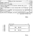
being replaced by the parity data. Fig. 4 is a figure showing
the relationship between the status of replacement of the parity
data and a specific tag.
Fig. 5 shows the management table of replacement by parity data.
In the first word of the 16-bit register, a 3-bit tag as shown
in Fig. 4 is set. In the second to third words, the start
address in the address region of the status indicated by the tag
is set. Further, in the fourth to fifth words, the end address
is set. This address is usually called LBA (Logical Block
Address).
The management table actually includes a plurality of registers
as described above. Fig. 6 shows a specific example of the
management table of actual replacement by parity data. This that
figure shows that the respective addresses are in the following
statuses. That is, the range of address 0-9999 and the range of
address 30000-39999 represent a status in which a broken HDD is
still connected and parity replacement has been completed
(register 1, register 4), the range of address 10000-19999
represents a status in which a broken HDD is still connected and
parity replacement is in process (register 2), and the range of
address 20000-29999 represents a status in which a broken HDD is
still connected, but a replacement work is not started (register
3).
Such management table in this embodiment may be written into non-volatile
not only registers but also non-volatile storage means,
for instance, EEPROM or accessible HDD. In the present invention
in which parity data and reconstructed data may be mixedly
stored, it is needed to reliably store whether the data stored
in a certain address is parity data or reconstructed data. If
the management table is written into a non-volatile storage
means, it is not lost even if the power is turned off by a power
failure or the like, and thus safety is assured.
In addition, it is possible to freely set the range of an address
region in which parity data is replaced by reconstructed data.
To restore all the lost data of a broken HDD, it is only needed
to specify the whole capacity of the HDD for the replacement
range. However, the address space of a disk array system is
tremendously large, and an enormous calculation time may be
required if its all regions are subjected only to replacement.
Accordingly, as replacement objects, only predetermined regions
may be chosen which have a high possibility that the host
computer may often accesses them. Further, it is also possible
to select to execute parity data replacement independently of the
access from the host computer. When the access from the host
computer is not often, it is also effective to previously perform
the replacement in expectation of the next access.
As described above, in the present invention, parity data stored
in a data storage device is replaced by reconstructed data and
the reconstructed data is stored, and thus the reduction of
performance in the data reconstruction can be suppressed without
further providing a redundant data storage device such as a
backup drive.
Claims (15)
- A method in which, if a broken data storage exists in a system having a plurality of data storage devices, the data stored in the broken data storage device is reconstructed based on the data stored in the other plurality of data storage devices, said method comprising of the steps of:reading data from the plurality of data storage devices;reading parity data from the data storage device in which said parity data is stored;reconstructing the data stored in the broken data storage device by carrying out logical operations of said data and said parity data; andstoring said reconstructed data by replacing said parity data stored in said data storage device by said reconstructed data.
- A method as set forth in Claim 1 further comprising a step of preparing a management table indicating whether said parity data stored in said data storage device has been replaced by said reconstructed data.
- A method as set forth in Claim 2 further comprising the steps of:receiving from the outside of the system a request to read the data stored in said broken data storage device;referencing said management table to determine whether said reconstructed data corresponding to said requested data is stored in said data storage device; andoutputting said reconstructed data to the outside if said reconstructed data is stored in said data storage device.
- A method as set forth in Claim 2 further comprising the steps of:receiving from the outside of the system a request to read the data stored in said broken data storage device;referencing said management table to determine whether said reconstructed data corresponding to said requested data is stored in said data storage device;if said reconstructed data is not stored in said data storage device, calculating a reconstructed data based on said data stored in said data storage devices other than said broken data storage device and said parity data;outputting said reconstructed data to the outside;storing said reconstructed data by replacing said parity data stored in said data storage device by said reconstructed data; and
updating said management table. - A method as set forth in Claim 1, 2, 3 or 4 further comprising a step of: if said broken data storage device is replaced by new said data storage device, said reconstructed data is stored by replacing said parity data stored in said data storage device by said reconstructed data.
- A method in which, if a broken data storage device exists in a system having a plurality of data storage devices, the data stored in the broken data storage device is reconstructed based on the data stored in the other plurality of data storage devices, said method comprising the steps of:reading data blocks from the plurality of data storage devices;specifying an address region to read from the data storage device in which parity data blocks are stored, said parity data block stored in said address region;obtaining a reconstructed data block by carrying out logical operations of said data blocks and said parity data block; andstoring said reconstructed data block in said address region.
- A method as set forth in Claim 6 further comprising a step of preparing a management table indicating the range of said address region and whether or not said reconstructed data block is stored in said address region.
- A method as set forth in Claim 7 further comprising a step of referencing said management table if the system receives a request to read the data block stored in said broken data storage device.
- A method as set forth in Claim 8 further comprising:a step of referencing said management table to determine whether or not said reconstructed data block is stored in said address region; anda step of outputting said reconstructed data block to the outside if said reconstructed data block is stored.
- A method as set forth in Claim 8 further comprising the steps of:referencing said management table to determine whether or not said reconstructed data block is stored in said address region;if said reconstructed data block is not stored, calculating a reconstructed data block based on said data blocks stored in said data storage devices other than said broken data storage device and said parity data block stored in said address region;outputting said reconstructed data block to the outside;storing said reconstructed data block in said address region; andupdating said management table.
- A method as set forth in Claim 6, 7, 8, 9 or 10 further comprising a step of storing said parity data block in said address region if the broken data storage device is replaced by new said data storage device.
- A data storage system having a plurality of data storage means in which, by storing parity data, the data stored in any broken data storage means of said plurality of data storage means can be reconstructed, said system comprising:a plurality of data storage means in which data and parity data are stored;data buses connected to said data storage means;calculation means connected to said data storage means and for reconstructing said data stored in any said data storage means generating a reconstructed data based on said data stored in the other said plurality of data storage means and said parity data; andmeans for writing said reconstructed data to replace said parity data stored in said data storage means.
- A system as set forth in Claim 12 further comprising management means for indicating whether said parity data stored in said data storage means has been replaced by said reconstructed data.
- A data storage system having a plurality of data storage means in which, by storing parity data, the data stored in any broken data storage means of said plurality of data storage means can be reconstructed, said system comprising:first data storage means having a parity data block stored in s specified address region;at least one second data storage means in which data blocks are stored;calculation means for reconstructing said data block stored in any said second data storage means by generating a reconstructed data block based on said parity block stored in said first data storage means and said data blocks stored in remaining said second data storage means; andmeans for storing said reconstructed data blocks in said address region.
- A system as set forth in Claim 14 further comprising management means for indicating the range of said address region and whether or not said reconstructed data is stored in said address region.
Applications Claiming Priority (1)
| Application Number | Priority Date | Filing Date | Title |
|---|---|---|---|
| PCT/JP1995/001157 WO1996042083A1 (en) | 1995-06-08 | 1995-06-08 | Data reconstruction method and data storage system |
Publications (1)
| Publication Number | Publication Date |
|---|---|
| EP0831484A1 true EP0831484A1 (en) | 1998-03-25 |
Family
ID=14125995
Family Applications (1)
| Application Number | Title | Priority Date | Filing Date |
|---|---|---|---|
| EP95921142A Withdrawn EP0831484A1 (en) | 1995-06-08 | 1995-06-08 | Data reconstruction method and data storage system |
Country Status (3)
| Country | Link |
|---|---|
| EP (1) | EP0831484A1 (en) |
| KR (1) | KR100300836B1 (en) |
| WO (1) | WO1996042083A1 (en) |
Cited By (2)
| Publication number | Priority date | Publication date | Assignee | Title |
|---|---|---|---|---|
| US6161194A (en) * | 1991-04-01 | 2000-12-12 | Hitachi, Ltd. | Data reconstruction method and system wherein timing of data reconstruction is controlled in accordance with conditions when a failure occurs |
| US9003140B2 (en) | 2011-08-22 | 2015-04-07 | Fujitsu Limited | Storage system, storage control apparatus, and storage control method |
Family Cites Families (3)
| Publication number | Priority date | Publication date | Assignee | Title |
|---|---|---|---|---|
| US4761785B1 (en) * | 1986-06-12 | 1996-03-12 | Ibm | Parity spreading to enhance storage access |
| US4849978A (en) * | 1987-07-02 | 1989-07-18 | International Business Machines Corporation | Memory unit backup using checksum |
| JP2923702B2 (en) * | 1991-04-01 | 1999-07-26 | 株式会社日立製作所 | Storage device and data restoration method thereof |
-
1995
- 1995-06-08 EP EP95921142A patent/EP0831484A1/en not_active Withdrawn
- 1995-06-08 WO PCT/JP1995/001157 patent/WO1996042083A1/en active IP Right Grant
- 1995-06-08 KR KR1019970708335A patent/KR100300836B1/en not_active IP Right Cessation
Non-Patent Citations (1)
| Title |
|---|
| See references of WO9642083A1 * |
Cited By (5)
| Publication number | Priority date | Publication date | Assignee | Title |
|---|---|---|---|---|
| US6161194A (en) * | 1991-04-01 | 2000-12-12 | Hitachi, Ltd. | Data reconstruction method and system wherein timing of data reconstruction is controlled in accordance with conditions when a failure occurs |
| US6625748B1 (en) | 1991-04-01 | 2003-09-23 | Hitachi, Ltd. | Data reconstruction method and system wherein timing of data reconstruction is controlled in accordance with conditions when a failure occurs |
| US6966011B2 (en) | 1991-04-01 | 2005-11-15 | Hitachi, Ltd. | Data reconstruction method and system wherein timing of data of data reconstruction is controlled in accordance with conditions when a failure occurs |
| US7434095B2 (en) | 1991-04-01 | 2008-10-07 | Hitachi, Ltd. | Data reconstruction method and system wherein timing of data of data reconstruction is controlled in accordance with conditions when a failure occurs |
| US9003140B2 (en) | 2011-08-22 | 2015-04-07 | Fujitsu Limited | Storage system, storage control apparatus, and storage control method |
Also Published As
| Publication number | Publication date |
|---|---|
| KR100300836B1 (en) | 2001-09-03 |
| KR19990021861A (en) | 1999-03-25 |
| WO1996042083A1 (en) | 1996-12-27 |
Similar Documents
| Publication | Publication Date | Title |
|---|---|---|
| US7308599B2 (en) | Method and apparatus for data reconstruction after failure of a storage device in a storage array | |
| US7206991B2 (en) | Method, apparatus and program for migrating between striped storage and parity striped storage | |
| US5088081A (en) | Method and apparatus for improved disk access | |
| EP0405926B1 (en) | Method and apparatus for managing a shadow set of storage media | |
| US5596709A (en) | Method and apparatus for recovering parity protected data | |
| JP3164499B2 (en) | A method for maintaining consistency of parity data in a disk array. | |
| US5566316A (en) | Method and apparatus for hierarchical management of data storage elements in an array storage device | |
| US8112679B2 (en) | Data reliability bit storage qualifier and logical unit metadata | |
| US6859888B2 (en) | Data storage array apparatus storing error information without delay in data access, and method, program recording medium, and program for the same | |
| US5875457A (en) | Fault-tolerant preservation of data integrity during dynamic raid set expansion | |
| US5826001A (en) | Reconstructing data blocks in a raid array data storage system having storage device metadata and raid set metadata | |
| US7228381B2 (en) | Storage system using fast storage device for storing redundant data | |
| EP0768606A2 (en) | RAID array data storage system with storage device metadata and RAIDset metadata | |
| US5933592A (en) | Promoting device level error to raidset level error to restore redundacy in a raid array data storage system | |
| GB2414592A (en) | Decreasing failed disk reconstruction time in a RAID data storage system | |
| US11347653B2 (en) | Persistent storage device management | |
| US6363457B1 (en) | Method and system for non-disruptive addition and deletion of logical devices | |
| US20210318739A1 (en) | Systems and methods for managing reduced power failure energy requirements on a solid state drive | |
| GB2343265A (en) | Data storage array rebuild | |
| EP0831484A1 (en) | Data reconstruction method and data storage system | |
| KR19980047273A (en) | How to Manage Cache on RAID Level 5 Systems | |
| JPH08286844A (en) | Parity generation control method and disk controller | |
| JP2005166016A (en) | Disk array device | |
| US20010052100A1 (en) | Data read/write controlling method, disk array apparatus, and recording medium for recording data read/write controlling program | |
| JP2857289B2 (en) | Disk array device |
Legal Events
| Date | Code | Title | Description |
|---|---|---|---|
| PUAI | Public reference made under article 153(3) epc to a published international application that has entered the european phase |
Free format text: ORIGINAL CODE: 0009012 |
|
| 17P | Request for examination filed |
Effective date: 19971128 |
|
| AK | Designated contracting states |
Kind code of ref document: A1 Designated state(s): DE FR GB |
|
| RAP1 | Party data changed (applicant data changed or rights of an application transferred) |
Owner name: INTERNATIONAL BUSINESS MACHINES CORPORATION |
|
| STAA | Information on the status of an ep patent application or granted ep patent |
Free format text: STATUS: THE APPLICATION HAS BEEN WITHDRAWN |
|
| 18W | Application withdrawn |
Withdrawal date: 20001214 |